


VIVOTEK SD83XXE Speed Dome
Mounting Accessories
AM-116/117 Pendant Pipe
AM-118 Pendant Head
AM-221 Gooseneck
AM-231 Parapet Mount
AM-519 Pendant Adaptor
Installation Guide
Corresponding part numbers:
AM-116: 900014300G
AM-117: 900014400G
AM-118: 900014600G
AM-221: 900014800G
AM-231: 900015000G
AM-519: 900014900G
Rev. 1.1
IP Surveillance
Revison History:
Rev. 1.0: Initial release
Rev. 1.1: Adding corresponding ordering part numbers and supported speed dome models.
I Compatible VIVOTEK Cameras
Speed Dome |
SD8364E, SD8363E, SD8333E, SD83x4E, SD83x6E, SD8362E |
|
|
II Mechanical Drawings
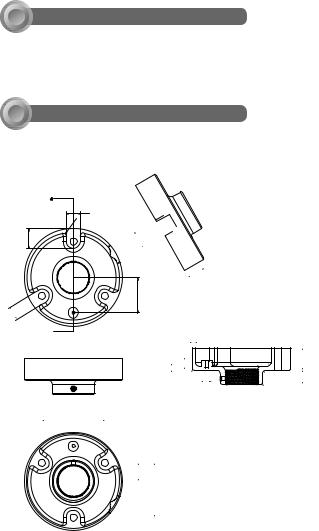
AM-118 Pendant Head
A
20
R5
28.04
26
R1 


. 2
.2 26
50
20
M6 
90
|
|
4 |
|
|
|
|
10 |
|
R8 R5 |
32.2 |
|
6 |
|
10 |
52.2 |
||
|
R2 |
15 |
20 |
|
|
|
|
|
|||
|
60.3 |
R5 |
|
|
|
|
|
|
|
||
|
|
R2 |
|
|
|
8.5 |
|
|
|
|
|
|
|
|
1-1/2" PS11 |
|
|
25.98 77.94
2

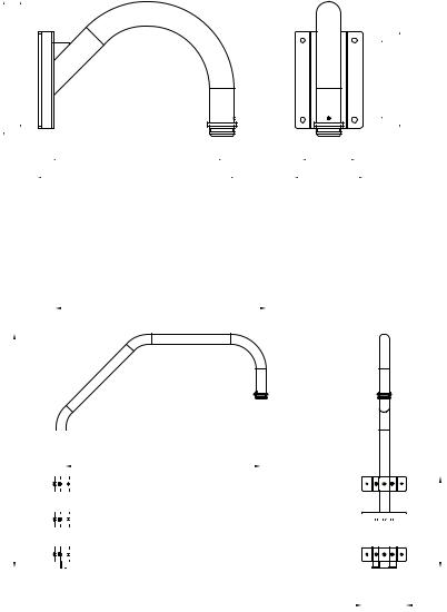
AM-116 20cm Pendant Pipe |
AM-117 40cm Pendant Pipe |
English
|
|
1 1/2" PS11 |
|
|
|
35 |
|
|
228 |
|
|
1 1/2" PS11 |
17 |
|
|
|
400 |
428 |
|
|
n 50.8 |
||
AM-519 Pendant Adapter |
1 1/2" PS11 |
|
|
(comes with the network camera) |
|
||
|
|
17 |
|
|
60,3 |
n 50.8 |
|
|
50,8 |
|
|
|
46 |
|
|
|
37,5 |
C4 |
|
5,38 5,25
5,25
R0,5
|
|
28 |
|
8 |
45 |
3 |
17 |
|
43,6
1-1/2" PS11X17mm (L)
3
AM-221 Gooseneck
278 |
262.19 |
350
405.8
AM-231 Parapet Mount
1077.95
1193 |
|
|
997 |
|
|
|
|
|
|
|
|
|
|
|
|
|
|
|
|
|
|
|
|
|
|
|
|
|
|
|
|
165.5 |
200 |
107.8
140


 463
463
228.15
4

AM-231 Parapet Corner Mount
1077.95
1193 |
|
|
|
997 |
|
|
|||
|
|
|
|
|
|
|
|
|
|
|
|
|
|
|
|
|
|
|
|
|
|
|
|
|
English
463
202.95
5
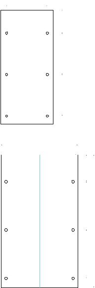
AM-231 Parapet Mount - Alignment Sticker
228.15
parapet top
178.15
100
n |
10 |
|
180
495
180
AM-231 Corner Mount - Alignment Sticker
287
143.5 |
|
PARAPET TOP |
|
|
|
|
100 |
|
|
n10 |
|
 Fold Line
180
495
180
6
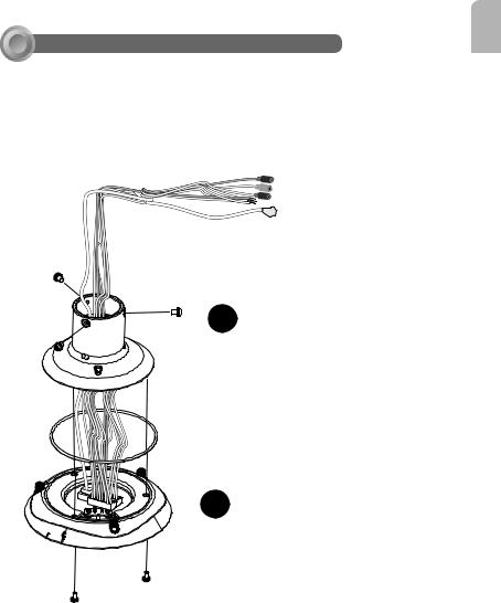
III Preparation before Installation
English
Connect Ethernet cable and IO wires (this may include the AC24V wires) to the interface section of the camera, and then combine the interface section with the dome cap. Note that you must route cables through the waterproof connector and the rubber seal plug, and install them to the dome cap. Please refer to the Quick Installation Guide for details.
Cabling should be done before mounting the camera.
2
The top section will look like this.
1
7

IV Mounting & Cabling
IV-1. Pendant Pipe Mounting: AM-116/-117 & AM-118
Shown below are the dimensions of a pendant mount configuration using the 40cm pendant pipe.
AM-118 

AM-117
446.2 mm
AM-519 

321.4 mm
204.8 mm |
8
 Loading...