


 Loading...
VIVOTEK - Built with
 Reliability
ND9322P
ND9424P Network Video Recorder
User’s Manual
H.265/H.264 • 8/16 CH • 8/16 port PoE • 2 HDDs • ONVIF • Fisheye Dewarp •
HDMI/VGA Monitor Display • RAID0/1 • VIVOCloud • POS Integration


 Rev. 1.0


 Rev. 1.3

User's Manual - 1 

VIVOTEK - Built with Reliability
Table of Contents
Chapter One Hardware Installation and Initial Configuration 8
Introducing the Network Video Recorder 8 Special Features 8 Safety 9 Chassis Dimensions 10 Physical Description 10 LED Indicators 28 Power Up and Power Down 29
Section One Management over a Local Console 30
Chapter Two Introduction to the Local Console Interface 30
2-1. How to Begin 32 2-2. Operation on Camera View Cell 38 2-2-1. PTZ Panel 38 2-2-2. Digital zoom Panel 41 2-2-3. Play Recording Clips Panel 42 2-2-4. DI/DO 43 2-2-5. Others 43 2-2-6. Right-click Commands 44
Chapter Three Configuation Using the Local Console 46
The Main Control Portal 46 3-1. Layout 46 3-2. DI/DO 46 3-3. Search recording clips 47 3-3-1. Basic Search 47 3-3-2. Alarm Search 51 3-3-3. Smart Search II 55 3-3-4. Smart VCA event search 58 3-3-5. Storyboard 66 3-4. Export recordings 70 3-5. Settings 72 3-5-1. Settings - Overview 72 3-5-2. Settings–Camera–Management 73 3-5-3. Settings–Camera–Recording 80 3-5-4. Settings–Camera–Recording 81 3-5-5. Settings–Camera–Media 83 3-5-6. Settings - Camera - Image 91 3-5-7. Settings–Camera–Motion Detection 93 3-5-8. Settings–Camera–PTZ settings 94 3-5-9. Settings–Alarm–Alarm 96 3-5-10. Settings - Alarm - Email 109
2 - User's Manual

VIVOTEK - Built with Reliability
3-5-11. Settings–System–Information 110
3-5-12. Settings–System–Maintenance 111 3-5-13. Settings - System - Display 112 3-5-14. Settings - System - UPS 113 3-5-15. Settings - System - Log 114 3-5-16. Settings - System - VIVOCloud service 116 3-5-17. Settings–User 117 3-5-17. Settings–User-Login / Logout 119 3-5-18. Settings–Storage 120
Storage Volume RAID Levels 122 3-5-19. Settings - Storage - Scheduled backup 127 3-5-20. Settings - Network 130 Settings - Network - IP 130 Settings - DDNS 131 Settings–Service 132
3-6. POS 136 3-7. Trend Micro IoT Security Service 138 3-8. Information 140
Section Two Management over a Web Console 141
Chapter Four Login and Getting Started 142
4-1. Login 142 4-2. Graphical Layout and Screen Elements - Liveview 146 4-2-1. Camera List Panel 147 4-2-2. Layout 149 4-2-3. Layout contents 150 4-2-4. Logo & Menu 150 4-2-5. View Cell panel 151 Adding Cameras to View Cells 151 4-2-6. PTZ panel 160 4-2-7. Alarm panel 162 4-3. Graphical Layout and Screen Elements - Search recording clips 166 4-3-1. Camera List Panel 167 4-3-2. Search Recording Clips Layout 168 4-3-3. Logo & Menu 168 4-3-4. View Cells in Search Recording Clips 169 Search Recording Clips Control Panel 170 4-3-5. Alarm Panel 172 4-3-6. Calendar Panel 173
Chapter Five System Settings 174
Chapter Six Operation............................................................................................................................................ |
176 |
6-1. Liveview 176 6-1-1. Placing Cameras into the Layout 176 6-1-2. PTZ and Other Screen Controls 180
User's Manual - 3
VIVOTEK - Built with Reliability
6-1-3. Audio 183 6-1-4. Camera Properties and Controls 184 6-1-5. Alarm Panel 185 6-1-6. Layout view Control Buttons 186 6-2. Search Recording Clips 187 6-2-1. Begin Playback and Search for Past Recordings 187 6-2-2. Past Alarms and Bookmarks 188 6-2-3. Synchronous Playback 189 6-2-4. Export media 190 6-2-5. Time Search 191
Safety and Compatibility.......................................................................................................................................... |
193 |
NOTE:
1.The NVR is only to be connected to PoE networks without routing to outside plants.
2.For PoE connection, use only UL listed I.T.E. with PoE output.
NOTE:
Use the NVR only with a DC power supply that is UL listed, and limited power source (LPS) certified. The power supply should bear the UL listed and LPS marks. The power supply should also meet any safety and compliance requirements for the country of use.
1.La NVR ne doit être raccordée qu’à des réseaux PoE, sans routage vers des installations extérieures.
2.Pour les raccordements PoE, utilisez uniquement un équipement de TI homologué UL, avec une sortie PoE.
REMARQUE :
n’utilisez la NVR qu’avec un bloc d’alimentation CC homologué UL, ainsi qu’avec une alimentation limitée (LPS) certifiée. Le bloc d’alimentation doit porter les indications d'homologation UL et LPS. Il doit également répondre aux exigences en matière de sécurité et de conformité relatives au pays d’utilisation.
 IMPORTANT:
The NVR also supports the VIVOCloud Retail app. Please refer to the VIVOCloud Retail app User Guide for details.
4 - User's Manual

VIVOTEK - Built with Reliability
Revision History
*Rev. 1.0: Initial release.
*Note that the Settings pages on the web console has been changed to that identical to the local console.
*Rev. 1.1: (for firmware release rev. 2.6.x)
1.Supports connections to legacy cameras via RTSP. See page 74.
2.Supports Trend Micro IoT Security Service and related options.
3.Supports Remote connection with VAST server. See page 133.
4.Supports plug-in-free web sessions using Chrome and Firefox browsers. Currently only 1 live view or 1 playback window is allowed per session.
* Rev. 1.2: for firmware rev. 3.0 and above.
-Supports Smart Search II for VCA (Video Contents Analysis) Smart Motion detection. The occurrences of Smart Motion alerts can be quickly searched and retrieved from stored videos.
See page 62 for details.
-Supports 3D counting analysis and scheduled reports.
-Supports event monitoring & event search for Smart VCA, Smart 360, and Smart Motion video analytics. See page 65. The triggers from VCA analytics detections can also be configured into system alarms. When triggered, the related video clips can be exported.
-Cybersecurity management for cybersecurity alert, event log, (page 147) and event logging. The NVR comes with TrendMicro security package, and can receive cyber attack information from cameras. Also, these events can be collected by the VAST software.
-Added the protection for access to live view from unauthorized users. See page 127.
-Updated the description for the Alarm search function. See page 50.
*Rev. 1.3:
-Updaed the max. PoE port output for single port to 30W.
User's Manual - 5
VIVOTEK - Built with Reliability
NOTE:
The following are the limitations for web access using the non-IE browsers:
1.Playback: fast forward, back forward, next frame buttons are not available.
2.Snapshot and Auto screen ratio not available on Safari.
3.Web browsers supported:
-Chrome v68.0.3440 and later official version
-Firefox v61.02 and later official version
4.OSes supported
-Windows
■Windows 7, 64 bit
■Windows 10
5.Minimum PC hardware requirements
1.CPU: Intel i5 4th generation and higher
2.RAM: 4GB and higher
Limitations on text entry length:
*User account: 64 alpha-numeric characters
*Account password: 64 alpha-numeric characters
*Path name: 256 alpha-numeric characters
*Supports all printable ASCII (0x21-0x7E) characters and space (ox20) for password.
!"#$%&\'()*+,-./0123456789:;<=>?@ABCDEFGHIJKLMNOPQRSTUVWXYZ[\]^_`abcdefghijklm nopqrstuvwxyz{|}~
*IP domain name: host.xxx.yyy.zzz - 63 bytes; total: 253 bytes
*Email account: local@domain_name_part - local -63bytes domain_name_part - 253 bytes.
 IMPORTANT:
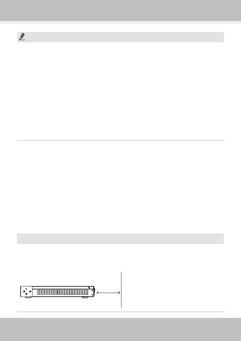
It is important to leave a clearance of 25cm behind the chassis. The clearance is required to ensure an adequate airflow through the chassis to ventilate heat.
To ensure normal operation, maintain ambient airflow. Do not block the airflow around chassis such as placing the system in a closed cabinet.
25cm
6 - User's Manual
VIVOTEK - Built with Reliability
Read Before Use
The use of surveillance devices may be prohibited by law in your country. The Network Camera is not only a high-performance web-ready camera but can also be part of a flexible surveillance system. It is the user’s responsibility to ensure that the operation of such devices is legal before installing this unit for its intended use.
It is important to first verify that all contents received are complete according to the Package Contents listed below. Take note of the warnings in the Quick Installation Guide before the Network Camera is installed; then carefully read and follow the instructions in the Installation chapter to avoid damage due to faulty assembly and installation. This also ensures the product is used properly as intended.
The Network Camera is a network device and its use should be straightforward for those who have basic networking knowledge. It is designed for various applications including video sharing, general security/surveillance, etc. The Configuration chapter suggests ways to best utilize the Network Camera and ensure proper operations. For creative and professional developers, the URL Commands of the Network Camera section serves as a helpful reference to customizing existing homepages or integrating with the current web server.
NOTE:
The operating system and management software are installed on a flash memory mounted on the main board. Except for running the plug-ins for the onscreen control on a web console, there is no need to install software.
Package Contents
■ ND9322P or ND9424P |
■ Mouse |
■ Power cord |
■ Screws |
■ Quick Installation Guide |
|
|
|
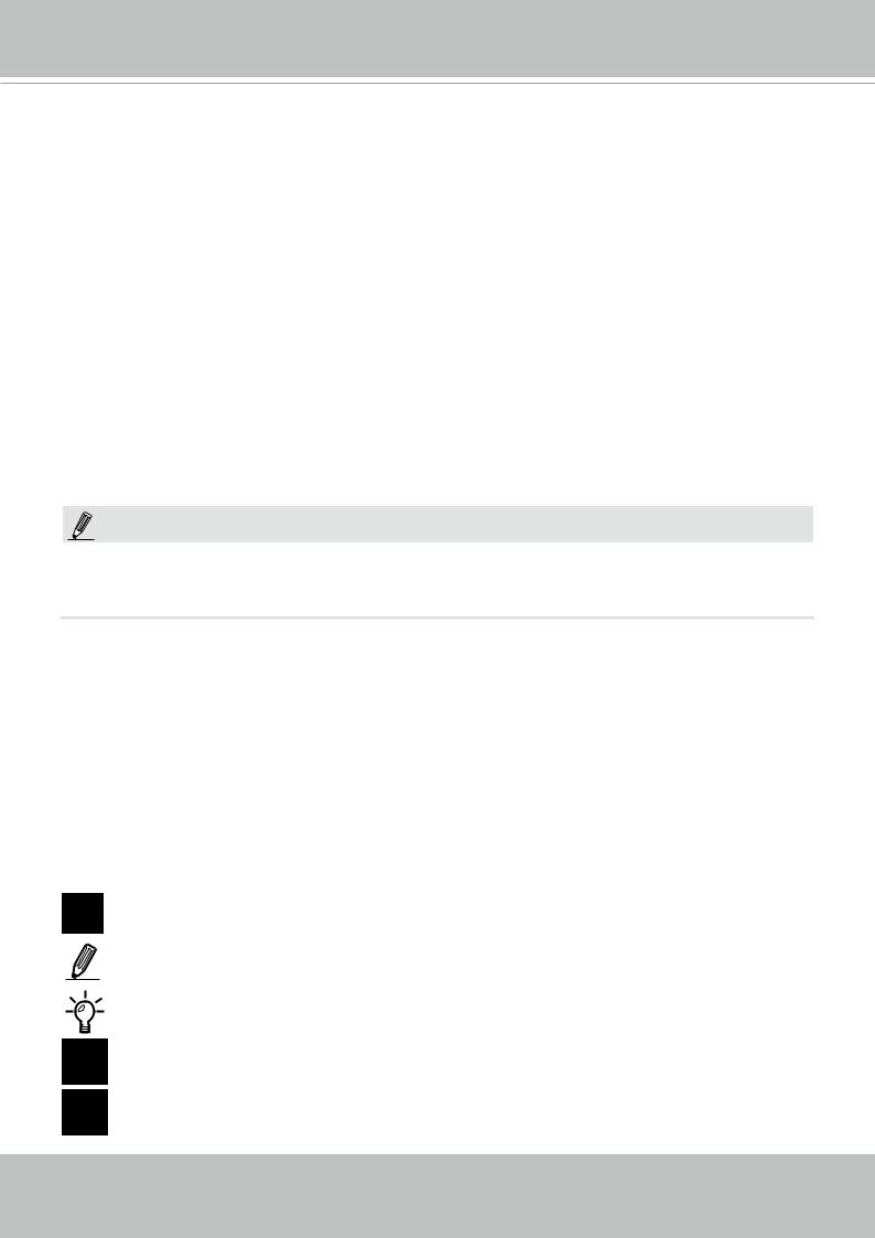
Symbols and Statements in this Document
i |
INFORMATION: provides important messages or advices that might help prevent inconvenient |
or problem situations. |
|
|
NOTE: Notices provide guidance or advices that are related to the functional integrity of the |
|
machine. |
|
Tips: Tips are useful information that helps enhance or facilitate an installation, function, or |
|
process. |
WARNING! or IMPORTANT: These statements indicate situations that can be dangerous or hazardous to the machine or you.
Electrical Hazard: This statement appears when high voltage electrical hazards might occur to an operator.
User's Manual - 7

VIVOTEK - Built with Reliability
Chapter One Hardware Installation and
Initial Configuration
Introducing the Network Video Recorder
VIVOTEK’s ND9322P and ND9424P are H.265 Linux-based standalone NVRs with embedded
PoE. Equipped for up to 8-CH/16-CH network cameras, the NVRs support 8x or 16x 802.3 at/ af PoE ports. Both also display the PoE power information, providing for a more convenient and smarter installation.
The NVR also supports remote and mobile access via VIVOCloud and iViewer apps for both iOS and Android handheld devices. The VIVOCloud app provides instant push notification and direct video playback functions when triggered by an alarm notification, providing users with a flexible and intelligent NVR for seamless use in small to medium sized video surveillance applications.
With H.265 compression technology and embedded with 2 HDD’s providing up to 16TB of storage space, the NVR offers greater than 30% more recording capacity than H.264 systems. This advancement provides users with more storage space for longer durations of video recording. In addition, the RAID 0/1 configurations provide further data security in the rare event of a hard drive failure.
For high-quality and detailed images, the NVR supports a maximum network camera resolution of 4K,12-Megapixels. To intelligently manage bandwidth while maintaining this high-quality, the “Auto Adaptive Stream” function will adjust the display resolution automatically for each different layout type. Furthermore, the NVR supports VIVOTEK’s fisheye network camera “Fisheye Dewarp” function, which provides multiple de-warping modes in live view and playback, ensuring the correct angle of video view and detailed information for flexible usage. Lastly, to quickly and intuitively find any target event, the NVR is equipped with the “Story-Board Search” function, which provides a glimpse of past recordings over an intuitive timeline.
The NVR supports HDMI and VGA local video output, so users can control the GUI OSD interface via mouse & keyboard, eliminating the need for a separate PC to search video or playback from the NVR. Additionally, the intuitive and friendly VIVOTEK GUI design gives users a smoother control experience.
Special Features
●Runs on embedded Linux
●1 x HDMI and 1 x VGA for local display
●2 x HDD bay
●1 x Gigabit RJ45 Ethernet port for uplink;
●2 x USB Ports (1 USB 2.0 in front and 1 USB 3.0 in Back)
●Size: 360 mm (W) x 311 mm (D) x 44 mm (H). Weight: 3.16kg (w/o HDD).
●8- or 16-CH Live View & 4-CH Synchronous Playback (web console)
●H.265 / H.264 / MJPEG
●Supports RAID0 and RAID1 volume configuration.
8 - User's Manual

VIVOTEK - Built with Reliability
●PTZ Support
●Snapshot / Export Media
●Digital zoom Video Control
●VIVOCloud for effortless access from cell phones using a QR code
●Terminal block pins for DI/DO connection.
●Configuration Backup / Restore
●Compatible with VIVOTEK VAST Central Management Software*
●Integration with VIVOTEK Network Cameras
●VIVOTEK iViewer Support (iOS/Android cellphone/hand-held devices)
*The VIVOTEK VAST Central Management Software is not included in the package.
Safety
Connect the system to an earthed main power outlet.
Never open the housing of the power supply unit.
Install and operate the system only in a dry, weather-proof location.
Observe the following safety factors:
•Is there visible damage to the system or power cord?
•Is the system operating correctly?
•Has the system been exposed to rain or moisture?
•Has the system been in a long storage under harsh conditions or exposed to unconforming stress?
The relevant electrical engineering regulations must be complied with at all times during installation.
Ensure that all maintenance and repair work is handled by qualified personnel such as electrical engineers or network specialists.
Read this manual before installing or operating the system. The documentation contains important safety instructions about permitted uses.
The rated AC input is: 100-240V~ 3.5A, 60-50Hz; the max. consumption: 170W (ND9322P),
250W (ND9424P).
If a fault occurs, disconnect the power cord from the power supply.
Do not install the system close to heaters or other heat sources. Avoid locations with direct sunlight.
All ventilation openings must not be blocked.
Use only the cables shipped with system or use appropriate cables that can withstand electromagnetic interference.
User's Manual - 9
VIVOTEK - Built with Reliability
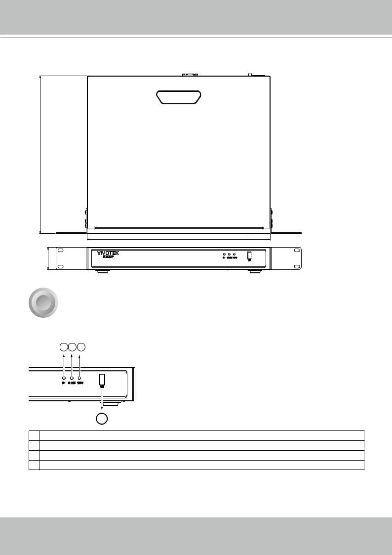
Chassis Dimensions
310.5 |
|
|
360 |
44 |
|
1 |
Physical Description |
 Front View
1 2 3
4 |
1Network uplink status/activity LED
2System status LED
3System power status
4USB 2.0 port
10 - User's Manual
VIVOTEK - Built with Reliability
 Rear View
|
|
|
6 |
7 |
2 |
|
|
8 |
5 |
3 |
1 |
10 |
9 |
4 |
1 |
PoE ports # 1 to #16 (ND9424P) |
6 |
Audio OUT |
2 |
RJ45 port - GbE uplink |
7 |
VGA |
3 |
HDMI |
8 |
DI/DO terminal block |
4 |
USB 3.0 port |
9 |
Reset button |
5 |
Audio IN |
10 |
Power socket (110/240V AC), w/ a power |
|
|
|
button |
 IMPORTANT:
The total power budget for the ND9322P’s 8 PoE ports is 120W. They can power 8x PoE class 3 (15.4W) cameras.
The total power budget for the ND9424P’s 16 PoE ports is 200W. Every 8 ports (#1 ~ #8 or #9 ~ #16) support 6x class 3 (15.4W) and 2x class 2 (7W) IP cameras.
The max. single port output can reach 30W, compliant with IEEE802.3at/af.
NOTE:
You can also use the Reset button to restore system defaults. Press and hold down the button for longer than 5 seconds. The system should start restoring defaults.
User's Manual - 11
VIVOTEK - Built with Reliability
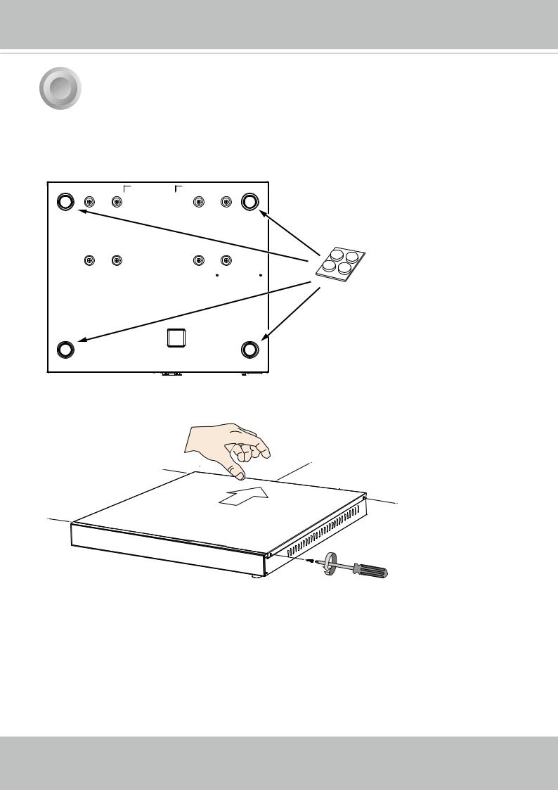
2 Hardware Installation
SATA hard disk(s) are user-supplied. The network video recorder can readily accommodate most of the off-the-shelf SATA hard drives.
1. Attach 4 foot pads to the bottom of the enclosure.
2.Use a screwdriver to loosen the retention screws on the sides and the back of the chassis.
Slide the top cover back, and then remove the top cover.
12 - User's Manual
VIVOTEK - Built with Reliability
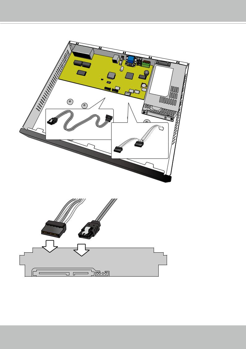
3. Connect SATA data and power cables to the main board.
SATA2 SATA1
J3
 SATA Data x2
SATA Power x1
4. Connect the SATA power and SATA data cables to the hard disk drives.
SATA power SATA data
User's Manual - 13

VIVOTEK - Built with Reliability
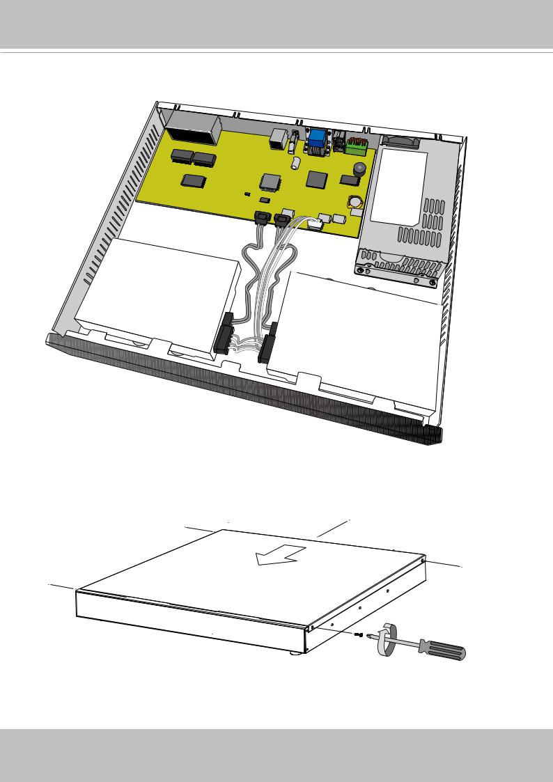
5.Install hard drives to the chassis. Note that the screws pass through the bottom of the chassis and secure the hard drives using the mounting holes at the bottom of hard drives. When installing hard drives, their label side should be facing up, and the connector side facing the inside of the chassis.
SATA2 SATA1
J3
When matching the screws and mounting holes on hard drives, you can let the enclosure stand on its side. Install two hard drives from the bottom of the chassis.
14 - User's Manual
VIVOTEK - Built with Reliability
6.Secure the hard disks to the mounting positions in the chassis with its label side facing up, and the connectors facing the inside of the chassis. The sample drawing below shows the positions.
SATA2
H.D.D.
SATA1
H.D.D.
7. When done, install the top cover.
User's Manual - 15
VIVOTEK - Built with Reliability
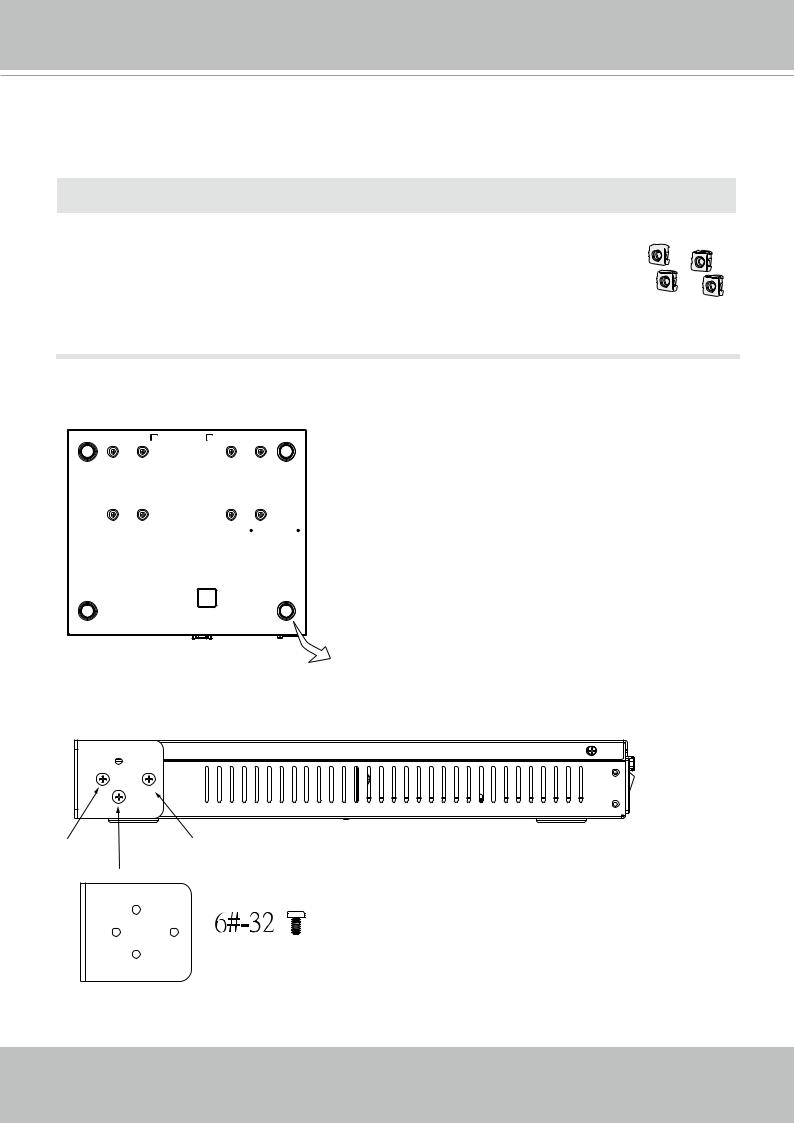
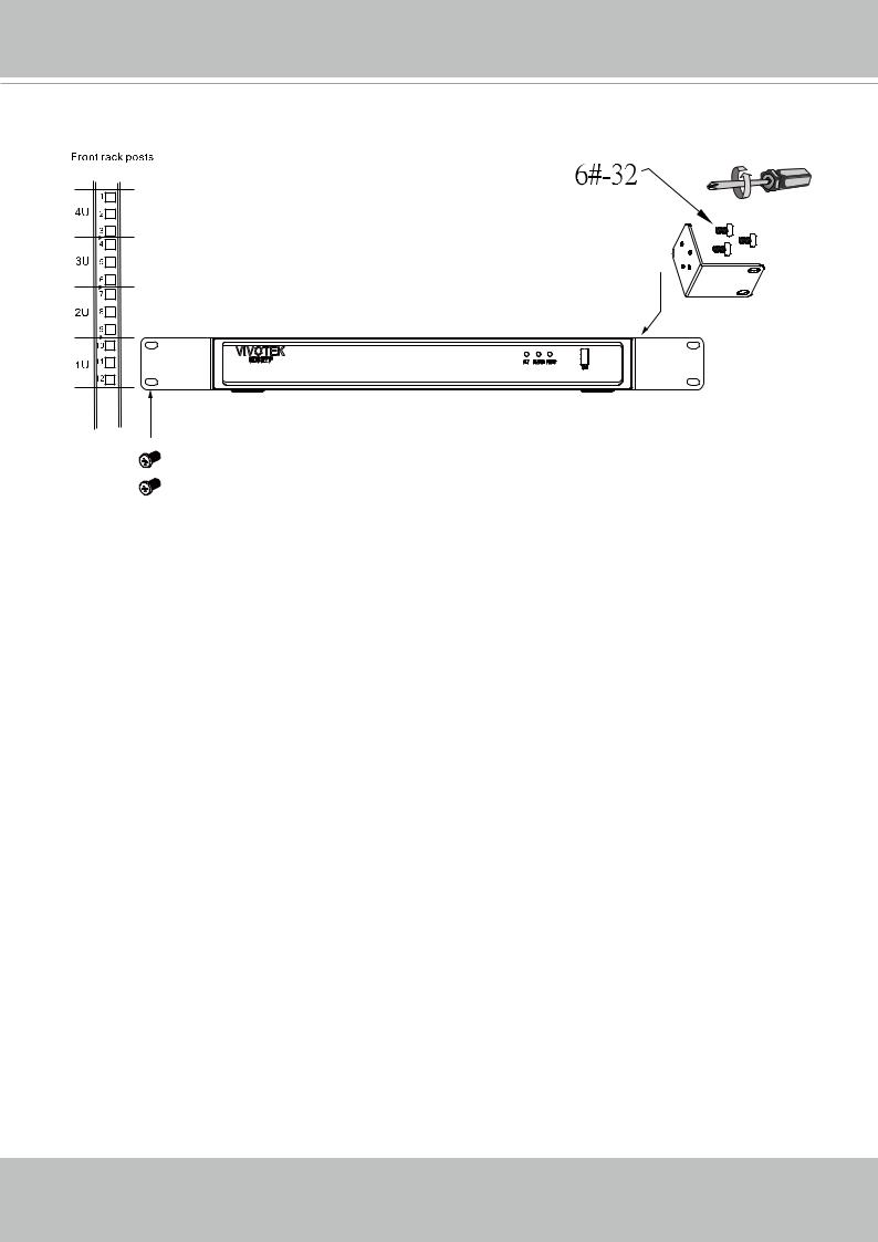
Rack-mounting (Optional, and the rack-mount brackets are separately purchased)
 IMPORTANT:
If you have either a round-holed or square-holed rack, install cage nuts or clip nuts to the desired positions on the rack posts. 

The instructions below are based on the installation to a 4-post equipment rack.
The slide rails apply to rack cabinet of a depth of 700 to 900mm. With 2 hard drives, the chassis can weigh up to 4kg.
If you need to install the NVR system into a rack cabinet, 1. Remove the foot pads from underneath the chassis.
 x4
x4
2. Secure the brackets to the sides of the chassis by driving 3 included screws.
16 - User's Manual
VIVOTEK - Built with Reliability
3. Secure the chassis to rack posts using 2 M6 screws on each side.
M6
User's Manual - 17
VIVOTEK - Built with Reliability
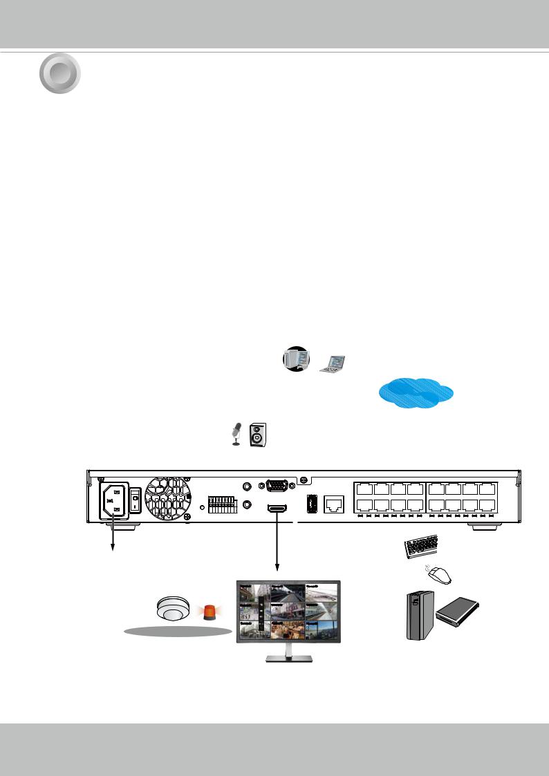
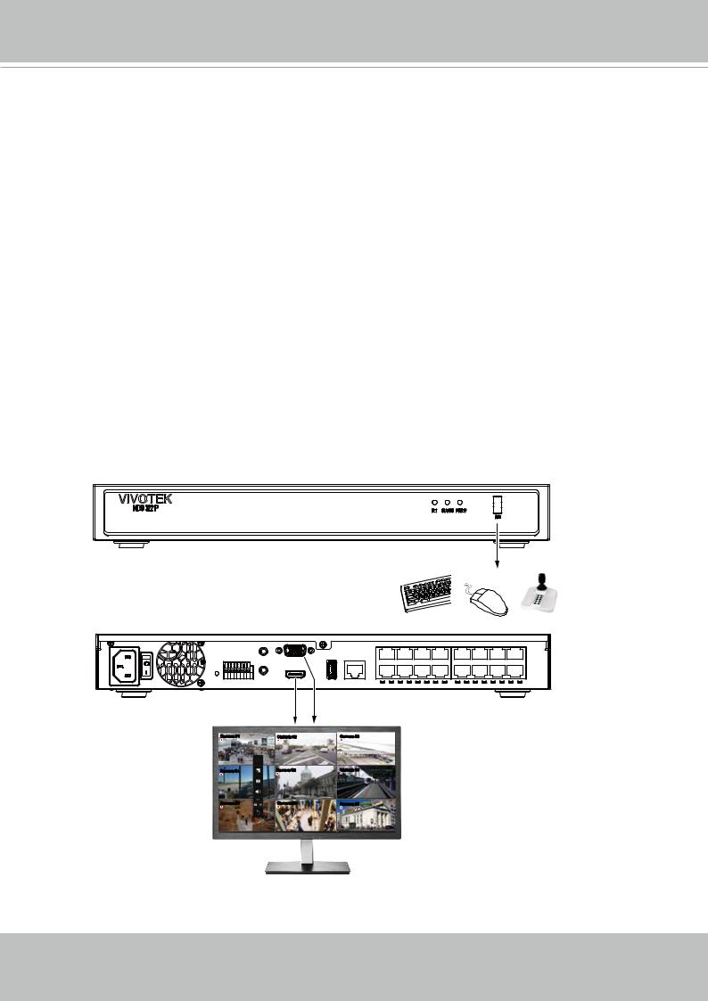
3 |
Interface Connections |
1.Connect to a monitor using an HDMI cable. VGA is also supported.
2.Connect CAT5e or better-quality Ethernet cable to the GbE Ethernet ports.
3.Connect USB devices such as, mouse, keyboard, USB optical drive, or USB thumb drive (formatted in FAT format), joystick, or UPS.
4.Connect external devices, such as sensors, relays, or alarms to the terminal block.
5.Connect the system to the power mains.
LAN/WAN |
LAN |
#1 ~ 8 or 16 PoE
USB 3.0 |
AC100~240V  50/60Hz
Camera 01 |
Camera 02 |
Camera 03 |
Camera 04 |
Camera 05 |
Camera 06 |
Camera 07 |
Camera 08 |
Camera 09 |
18 - User's Manual

VIVOTEK - Built with Reliability
 NOTE:
NOTE:
1.Although the system supports MAC Binding, the system should be able to detect VIVOTEK's cameras within the network regardless of the presence of a DHCP server. Ideally, cameras and the NVR should reside in the same subnet. If a camera's IP is changed for some reasons, the system should be able to detect its new IP.
2.Note on external storage enclosure via the USB 3.0 interface:
2-1. If external USB 3.0 storage is attached, a max. volume size of 16TB is supported. The NVR supports the connection to a USB3.0 storage with a maximum of 5 disk drives. The minimum storage size in the external storage is 64GB.
2-2. The external storage must be powered on first before the NVR.
2-3. Hot-swapping is not supported. If the external storage is disconnected, recording will be continued using the NVR's internal disk drives.
2-4. The storage configuration on the external storage is separately configured, e.g., RAID configuration. The RAID volume on the external storage appears to the NVR as a single large disk drive, and you should create a volume from it from the Storage configuration page.
2-5. If the disk drives in the external storage are not configured into the NVR's storage volumes, you can use them as the external backup devices. To do so, you should format disk drives in the external storage in the FAT32 or NTFS format, and export the recorded video on NVR to these disk drives.
2-6. Limitations:
•When you are exporting video to the disk drives in an external storage, you cannot select the other disk drives to create a new volume.
•If the disk drives or volumes in the external storage is smaller than 1TB, you cannot configure them as volumes for the NVR.
•The connection interface to external storage must comply with the USB 3.0 specifications.
2-7. The RAID or volume configuration in the NVR does not extend to include devices in the external storage.
User's Manual - 19
VIVOTEK - Built with Reliability
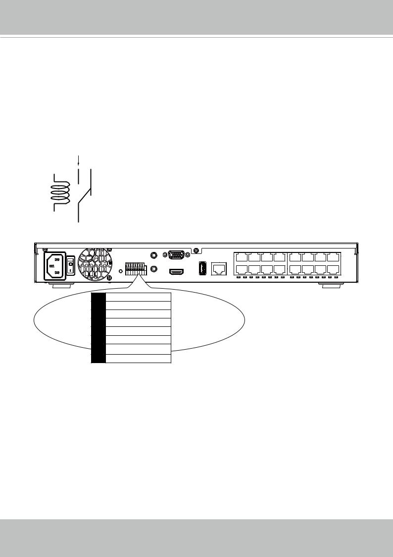
Terminal Block Connections
The terminal block pinouts is shown as follows:
The relay pins default status is set to Normally Open. Connect your relay or external devices’ signal wires to the system, the system will automatically detect the current signal status. You can then trigger the external devices using the DI/DO panel on the live view.
You can also configure the system alarm setting for the system to automatically trigger a relay pin on the occurrence of system events. See Alarm settings on page 96.
Normally Open pin
 Normally Closed
pin
Coil
Common pin
1Relay_NO
2Relay_COM
3DI1
4DI2
5DI3
6DI4
7GND
8GND
The GND are common ground for the DIs.
20 - User's Manual
VIVOTEK - Built with Reliability
 WARNING:
If you connect the NVR to a PoE port of the AW-FED series PoE switch, make sure you turn off the PoE output on that specific port using the onboard DIP switch. Otherwise, the high power output can damage the LAN port on NVR.
PoE cameras
AW-FED PoE switch
1 2 3 4 5 6 7 8
ON
PoE ON/OFF switch
NVR
User's Manual - 21
VIVOTEK - Built with Reliability
4 Initial Configuration - via a Local Console
A local console requires the following:
1.A monitor is connected via an HDMI or VGA cable.
2.A mouse and/or a keyboard are connected to the system.
3.It is presumed that the system has not been configured yet.
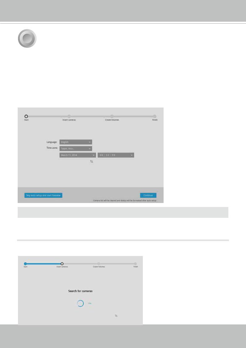
Follow the onscreen messages to complete the initial configuration:
1.Select the UI language, Time zone, and current date and time. Click on the Continue button to proceed. Make sure you enter the correct date and time.
 IMPORTANT:
Except in the initial setup, changing system time can produce disruptions to the existing recordings. Turning the current system time back to a time when video recording was taking place can generate duplicate files. And those files may not be playable.
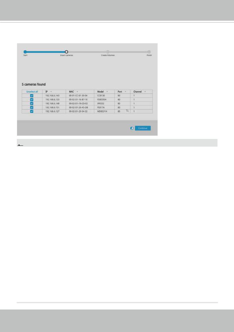
2. The system will then start to scan the local subnet for connected cameras.
22 - User's Manual
VIVOTEK - Built with Reliability
3.All cameras detected on the network will be automatically selected. If necessary, deselect the cameras you want to exclude from the configuration. Click Continue to proceed.
 NOTE:
NOTE:
1.The maximum decoding bandwidth is
H.265
3840x2160@30fps 1 CH 1920x1080@120fps 4 CH
H.264
3840x2160@30fps 1 CH
1920x1080@120fps 4 CH
Recording throughput:
64Mbps (ND9322P); 96Mbps (ND9424P)
Pre-recording: 5 seconds (max. 10)
Post-recording: 20 seconds (max. 300)
When cameras are recruited into the configuration, their stream 1 is used as the recording stream.
The resolution and fps (frame rate per second) of stream 1 may vary depending on the specifications of different cameras.
2.If there are less than 8 or 16 cameras, the Auto Setup will automatically move to the next configuration step.
User's Manual - 23
VIVOTEK - Built with Reliability
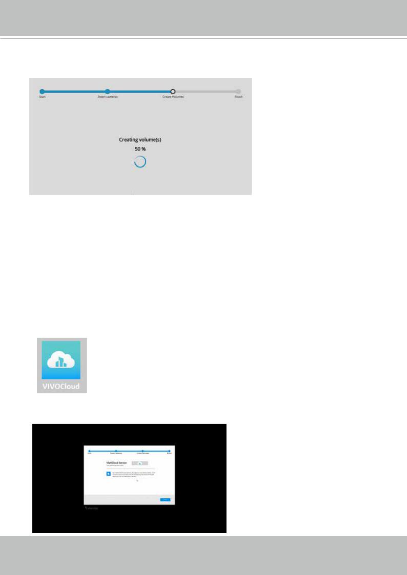
4.The system will automatically create volumes from the installed disk drives. The process will take several minutes. Hard disks will be configured into single-disk volumes. You can delete these volumes and then create RAID volumes in the Settings > Storage page.
5.An optional utility, VIVOCloud, is available through the Apple and Android App Stores. The
VIVOCloud works with a server hosted by VIVOTEK for bridging and tunneling video requests between client devices and network cameras/CMS/NVR. The utility simplifies and facilitates network configuration for access across the Internet.
The prerequisites for using the VIVOCloud are as follows:
1.Download and install the VIVOCloud utility to your cell phone.
2.Both the NVR and your cell phone have access to the Internet.
With this utility, you do not need to configure IP port forwarding on router or set up a DDNS address for the NVR. You do not even need to know the IP address of the NVR. The VIVOCloud utility automatically manages the network parameters required for making the connection. The VIVOCloud comes with viewing and playback interfaces very similar to those in the iViewer utility.
To connect the NVR from a cell phone using the VIVOCloud: 5-1. Click on the VIVOCloud button on the wizard.
24 - User's Manual
VIVOTEK - Built with Reliability
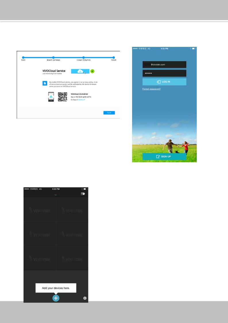
5-2. The QR code will be generated.
5-3. Open the QR code utility from your cell phone. If you already registered an account, tap LOG IN. If not, tap SIGN UP to register an account from a VIVOTEK server.
User
The NVR also supports the VIVOCloud Retail app.
Please refer to the VIVOCloud Retail app User
Guide for details.
5-4. You can be defaulted to the Live view page. Tap the Add button below to add devices.
User's Manual - 25
VIVOTEK - Built with Reliability
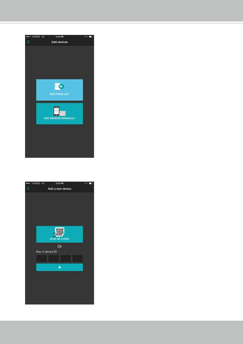
5-5. Tap the ADD DEVICES MANUALLY button.
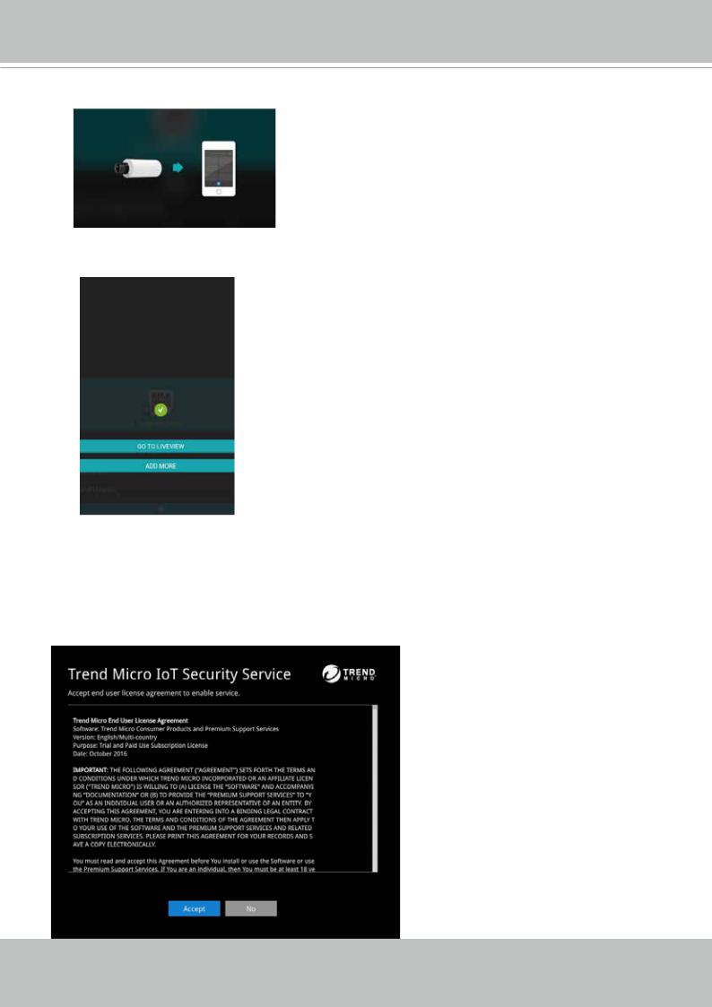
5-6. You can then point your cell phone lens at the NVR screen (Step 5-3.) and use the SCAN QR CODES function to establish the connection. You may also manually enter the device ID.
26 - User's Manual
VIVOTEK - Built with Reliability
5-7. The process will take several seconds to complete.
5-8. The NVR and the cameras under it will be ready for access.
6.Click the Done button.
7.Read the Trend Micro IoT Security Service licencse statement. Click the Accept button when done.
The LiveClient screen will display, and, by default, the recording from the selected cameras will immediately take place.
User's Manual - 27
VIVOTEK - Built with Reliability
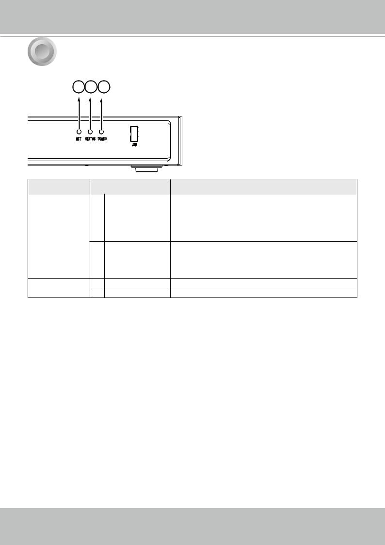
5 LED Indicators
1 2 3
Name |
Behavior |
Definitions |
||
|
|
|
|
|
1. |
NET LED |
1 |
Blinking Orange |
Data is being transmitted or received. |
|
|
2 |
OFF |
The Ethernet uplink is disconnected. |
2. |
Status LED |
1 |
Constant Green |
System ready. |
|
|
2 |
Blinking Green |
Updating firmware or device pack. |
|
|
|
every 1 second |
|
3Constant Red 1. S.M.A.R.T.-related disk errors,
2.A configured H.D.D. is missing,
3.H.D.D. is full. Buzzer will also be sounded. When buzzer is turned off, LED will return normal.
3. Power LED 1 |
Solid Green |
The NVR is powered on. |
2 |
OFF |
The NVR is powered off. |
28 - User's Manual
VIVOTEK - Built with Reliability
6 Power Up and Power Down
To power up and power down,
On the initial configuration:
1.Connect the power cord between the system and power outlet.
2.Turn on the system using the power button on the back of chassis.
After the initial connection,
Use the power down button on the lower right corner of the Settings page. The system should start flushing the cached contents in system memory and gracefully shut down. You should then flip the power switch button on the back of chassis to completely shut down the system.
Press the Reset button for longer than 5 seconds can restore system defaults.
 WARNING:
1.No storage system is completely fail-safe. Damage to data might occur due to file system corruption, operating system malfunction, virus infection, HDD component failures, and so on. Therefore, it is highly recommended to regularly back up your data, and VIVOTEK disclaims responsibilities of data loss or recovery.
2.Always power off the system using the power button on the back of chassis. The system is powered off when you observe that all LEDs go off. Do not disconnect the power cord while the system is still operating. Doing so will result in data inconsistencies. The normal power-off procedure allows cached data to be written to disks.
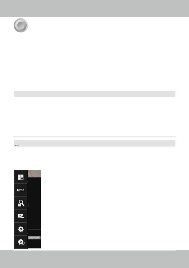
 NOTE:
NOTE:
If system buzzer is sounded, move your mouse cursor to reveal the main screen portal, and then click on the Stop buzzer button.
Serious system faults, such as a missing volume, can trigger the system buzzer. Verify the cause of system fault and turn off the buzzer.
User's Manual - 29
VIVOTEK - Built with Reliability
Section One
Management over a
Local Console
Chapter Two
Introduction to the Local Console Interface
Camera 01 |
Camera 02 |
Camera 03 |
Camera 04 |
Camera 05 |
Camera 06 |
Camera 07 |
Camera 08 |
Camera 09 |
30 - User's Manual
Loading...