


FD836BA-HTV
FD836BA-HVF2, FD836BA-HTV,
FD836BA-EHVF2, FD836BA-EHTV
User’s Manual
H.264 • 2MP • 30M IR • P-iris • Smart Stream • Smart IR
Fixed Dome
Network Camera
Rev. 1.0

VIVOTEK
Table of Contents
Overview
Revision History ...............................................................................................................................................4
Read Before Use ..............................................................................................................................................4
Package Contents ............................................................................................................................................4
Symbols and Statements in this Document ......................................................................................................4
Physical Description .........................................................................................................................................5
Hardware Installation ........................................................................................................................................6
Network Deployment ......................................................................................................................................17
Software Installation .......................................................................................................................................20
Ready to Use ..................................................................................................................................................21
Auto Focus (for Motorized Lens Models only) ................................................................................................22
Accessing the Network Camera
Using Web Browsers ......................................................................................................................................23
Using RTSP Players .......................................................................................................................................26
Using 3GPP-compatible Mobile Devices ........................................................................................................27
Using VIVOTEK Recording Software .............................................................................................................28
Main Page
Client Settings
Conguration
System > General settings .............................................................................................................................40
System > Homepage layout ..........................................................................................................................42
System > Logs ...............................................................................................................................................45
System > Parameters ....................................................................................................................................47
System > Maintenance ...................................................................................................................................48
Media > Image .............................................................................................................................................52
Media > Video ..............................................................................................................................................66
Media > Audio.................................................................................................................................................75
Network > General settings ............................................................................................................................76
Network > Streaming protocols ....................................................................................................................84
Network > SNMP (Simple Network Management Protocol) ...........................................................................93
Security > User accounts ...............................................................................................................................94
Security > HTTPS (Hypertext Transfer Protocol over SSL) .................................................................95
Security > Access List ................................................................................................................................102
PTZ > PTZ settings ......................................................................................................................................107
Event > Event settings.................................................................................................................................. 111
Applications > Motion detection....................................................................................................................125
Applications > DI and DO ...........................................................................................................................128
Applications > Tampering detection .............................................................................................................129
Applications > Audio detection ...................................................................................................................130
Applications > Package management - a.k.a., VADP (VIVOTEK Application Development Platform) .......132
Recording > Recording settings ..................................................................................................................135
Local storage > SD card management .........................................................................................................140
Local storage > Content management .........................................................................................................141
Appendix
2 - User's Manual
..............................................................................................................................................................
....................................................................................................................
.........................................................................................................................................................
..................................................................................................................................................
....................................................................................................................................................
........................................................................................................................................................
3
23
29
34
39
144

VIVOTEK
URL Commands for the Network Camera ................................................................................................ 144
Technical Specications ........................................................................................................................... 317
Technology License Notice ....................................................................................................................... 319
Electromagnetic Compatibility (EMC) .......................................................................................................320
Overview
VIVOTEK’s FD836BA is a series of robust, dome-style network cameras designed for diverse
outdoor applications and offering a broad range of options. Equipped with a Full HD sensor
enabling viewing resolution of 1920x1080 at a smooth 30 fps, the FD836BA series is an all-in-one
outdoor cameras capable of capturing high quality and high resolution video at up to 2 Megapixels
whether in high contrast or low light with WDR and SNV technology.
Further increasing its exibility, VIVOTEK’s FD836BA series provides options for both xed focus
for simple operation without extra electrical power, and remote focus with built-in stepping motors
and P-iris to provide precise adjustment remotely.
To meet the demands of any harsh outdoor application, VIVOTEK’s FD836BA series is also armed
with IP66-rated housing to help the camera body withstand rain, dust and high pressure water
jets from any direction, while its IK10-rated housing provides robust protection against acts of
vandalism or other impacts.
Finally, a wide operating temperature range further enhances the camera’s performance and
reliability in extremely cold or hot weather, even when using PoE. When choosing VIVOTEK
FD836BA series, customers will be offered four options: the FD836BA-HVF2, FD836BA-EHVF2,
FD836BA-HTV, and FD836BA-EHTV. Different options can be chosen based on the requirements
of your application, such as the need for a specific focusing method or operating environment
temperature.
With the highly exible VADP (VIVOTEK Application Development Platform), users can extend the
features of this series by adding third-party applications for the camera. Thus, the series is not only
equipped with multiple focusing methods and wide temperature range options, is but ideal for a
wide variety of applications.
User's Manual - 3
VIVOTEK
i
Revision History
■ Rev. 1.0: Initial release.
Read Before Use
The use of surveillance devices may be prohibited by law in your country. The Network Camera
is not only a high-performance web-ready camera but can also be part of a exible surveillance
system. It is the user’s responsibility to ensure that the operation of such devices is legal before
installing this unit for its intended use.
It is important to first verify that all contents received are complete according to the Package
Contents listed below. Take note of the warnings in the Quick Installation Guide before the Network
Camera is installed; then carefully read and follow the instructions in the Installation chapter to
avoid damage due to faulty assembly and installation. This also ensures the product is used
properly as intended.
The Network Camera is a network device and its use should be straightforward for those who
have basic networking knowledge. It is designed for various applications including video sharing,
general security/surveillance, etc. The Configuration chapter suggests ways to best utilize the
Network Camera and ensure proper operations. For creative and professional developers, the URL
Commands of the Network Camera section serves as a helpful reference to customizing existing
homepages or integrating with the current web server.
Package Contents
■ FD836BA-HVF2, FD836BA-HTV, FD836BA-EHVF2, FD836BA-EHTV
■ Screw pack
■ Quick Installation Guide & alignment sticker
Symbols and Statements in this Document
INFORMATION: provides important messages or advices that might help prevent
inconvenient or problem situations.
NOTE: Notices provide guidance or advices that are related to the functional integrity of
the machine.
Tips: Tips are useful information that helps enhance or facilitae an installation, function,
or process.
WARNING! or IMPORTANT!: These statements indicate situations that can be
dangerous or hazardous to the machine or you.
Electrical Hazard: This statement appears when high voltage electrical hazards might
occur to an operator.
4 - User's Manual
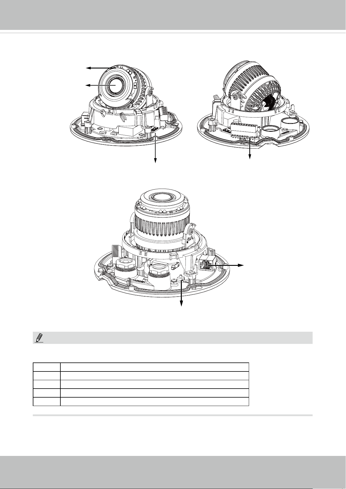
Physical Description
IR LEDs
Motorized or
xed lens
VIVOTEK
SD/SDHC/SDXC
Card Slot
Reset button
Terminal block
RJ45
Ethernet port
NOTE:
The "T" and "HT" models have an auto-focus motorized lens. Some of the sufx syntax are
listed below:
E w/ heater for extreme weather
Fx Focal length w/ number
T w/ Remote focus lens
R w/ PoE repeater
H w/ High Dynamic Range functionality also known as WDR
User's Manual - 5
VIVOTEK
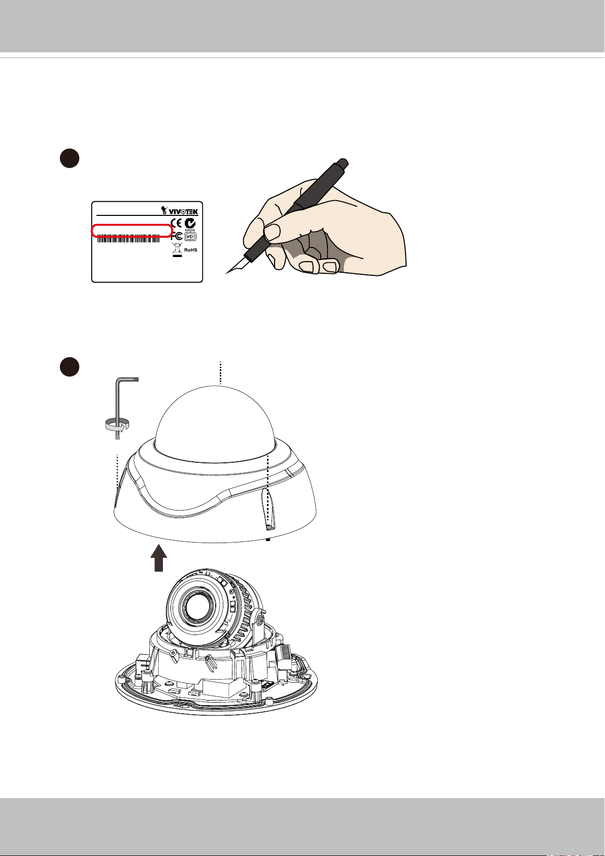
Hardware Installation
1. Jot down the camera's MAC address for later reference. This is especially important if
you install numerous cameras at an installation site.
1
Network Camera
Model No: XXXXXX
MAC: 0002D1083236
This device complies with part 15 of the FCC Rules. Operation is subject to
the following two conditions:
(1) this device may not cause harmful interference, and
(2) this device must accept any interference received, including interference
that may cause undesired operation.
Pat. 6,930,709
2. Remove the dome cover by loosening the retention screws on the dome cover.
Made in Taiwan
2
6 - User's Manual
VIVOTEK
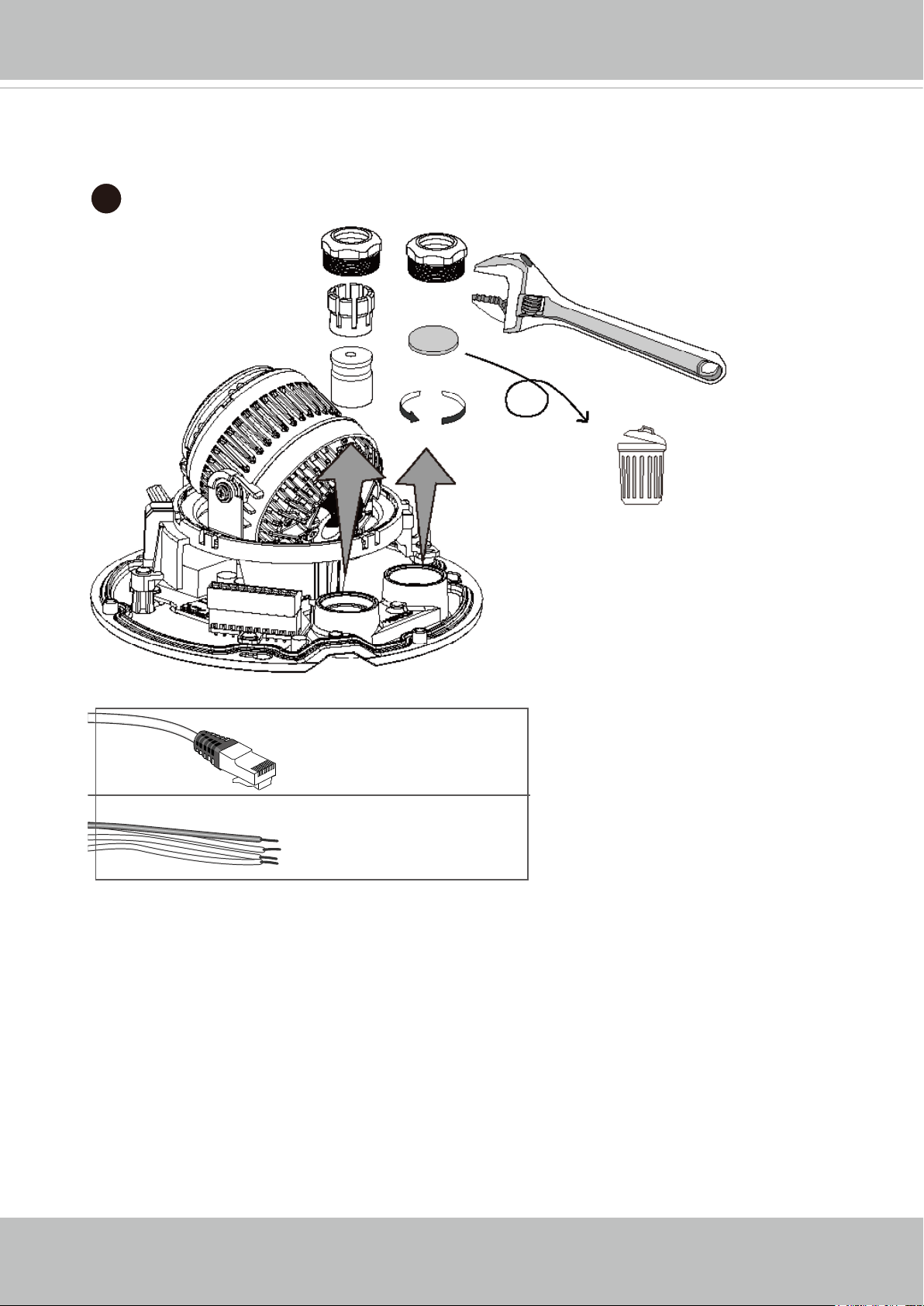
3. Loosen and remove the waterproof connectors. Discard the plastic stopper inside the IO
connector
3
5~6.3mm
DI/DO: 1.8~2.1mm
User's Manual - 7
VIVOTEK
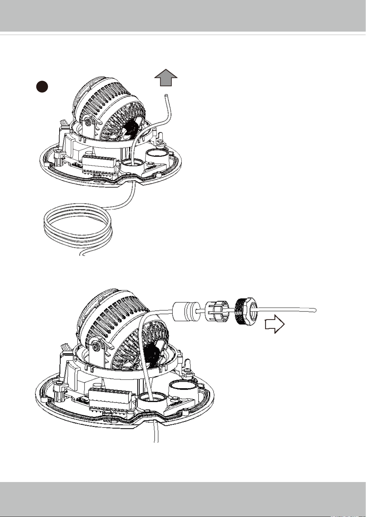
4. Insert an Ethernet cable through the cabling hole.
4
5. Insert the Ethernet cable through the cable gland, and the rubber seal.
5
8 - User's Manual
VIVOTEK
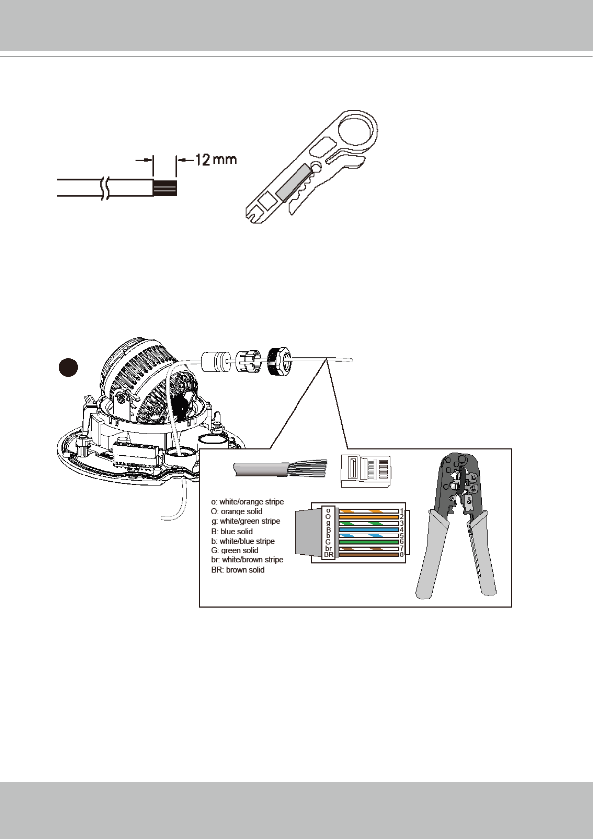
6. Remove part of cable sheath.
6
7. You will need an RJ45 crimping tool to attach the Ethernet wires to a connector. When
done, connect the cable to the camera’s Ethernet RJ45 socket.
7
User's Manual - 9
VIVOTEK
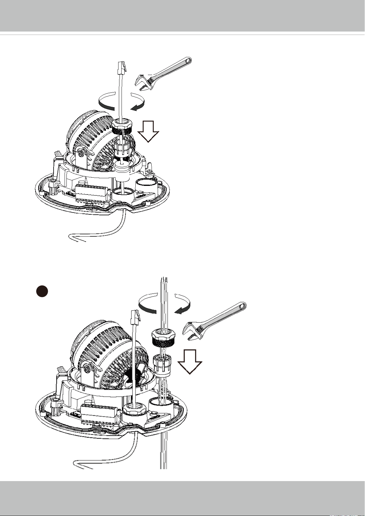
8. Secure the connection by tightening the waterproof components.
8
9. Secure the IO cable connection by tightening the waterproof components. Note that the
waterproof cable rubber seal must be installed whether you connect IO wires or not.
9
10 - User's Manual
VIVOTEK
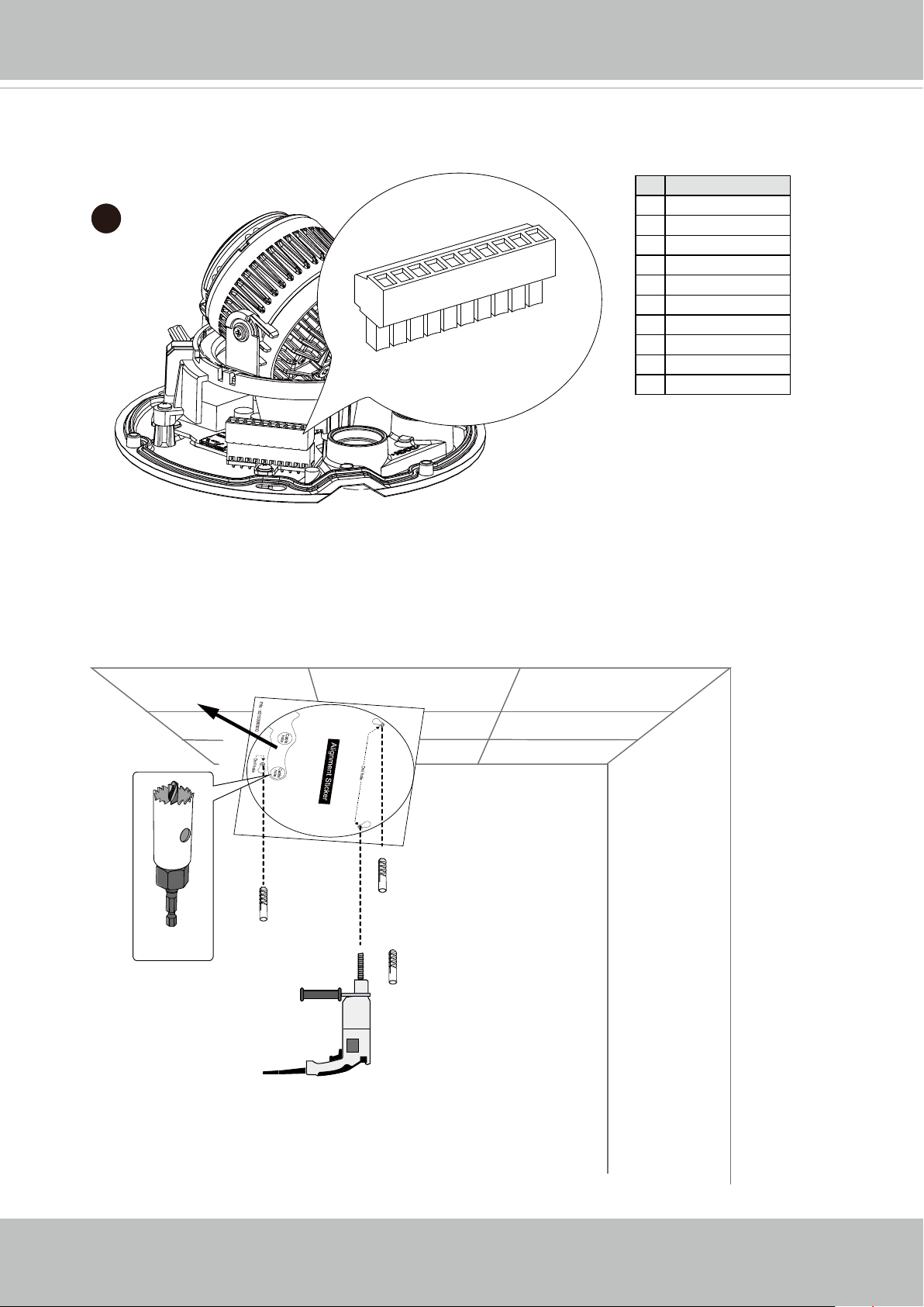
10. If applied, connect DI/DO wires, 12V DC power, or audio wires to the terminal block.
# Name
1 EXT_MIC_N
10
10
9
8
7
6
5
4
3
2
1
2 EXT_MIC_P
3 Audio_out4 Audio_out+
5 DI6 DI+
7 DO8 DO+
9 12V DC-_IN
10 12V DC+_IN
11. Attach the included alignment sticker to a preferred location. Drill holes for mounting
screws and if preferred, drill one or two routing holes.
A
User's Manual - 11
VIVOTEK
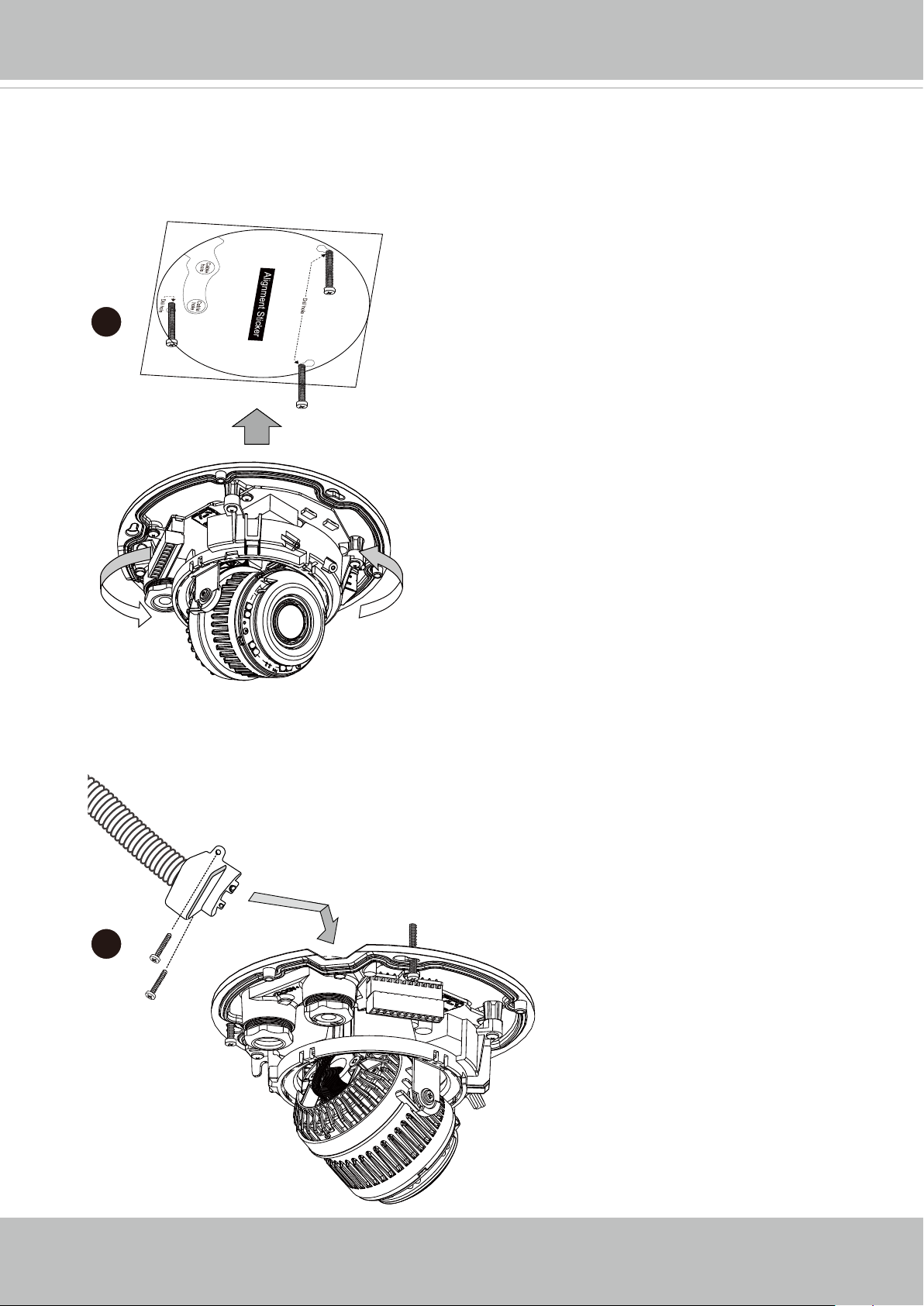
12. When fastening the screws, do not completely tighten the screws. Pass cables through
the routing holes, and then mount the camera by passing the screw heads through the
keyhole slots. Turn the camera counter-clock wise, and then fasten the screws.
12
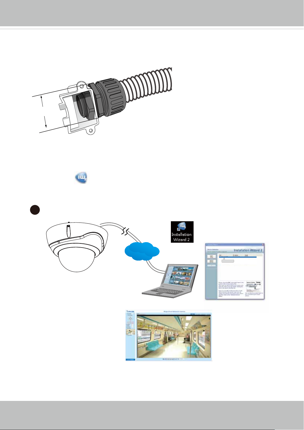
13. If you route your cables through the side opening, you can use the side bushing to
connect a protective 3/4" conduit. The conduit is user-supplied. You can use the included
screws to secure the side bushing to wall.
3/4"
13
12 - User's Manual
VIVOTEK
Please avoid using a conduit with a hex nut larger than 35mm.
≤3/4”
Ø< 35mm
14. Install the "Installation Wizard 2" software utility from your software CD. The program
will search for VIVOTEK Video Receivers, Video Servers or Network Cameras on the
same LAN.
Double-click on the camera’s MAC address to open a browser management session
with the camera.
14
IW2
LAN
Browser
00-02-D1-73-02-02 192.168.5.151 FD8168
0002D1730202
User's Manual - 13
VIVOTEK
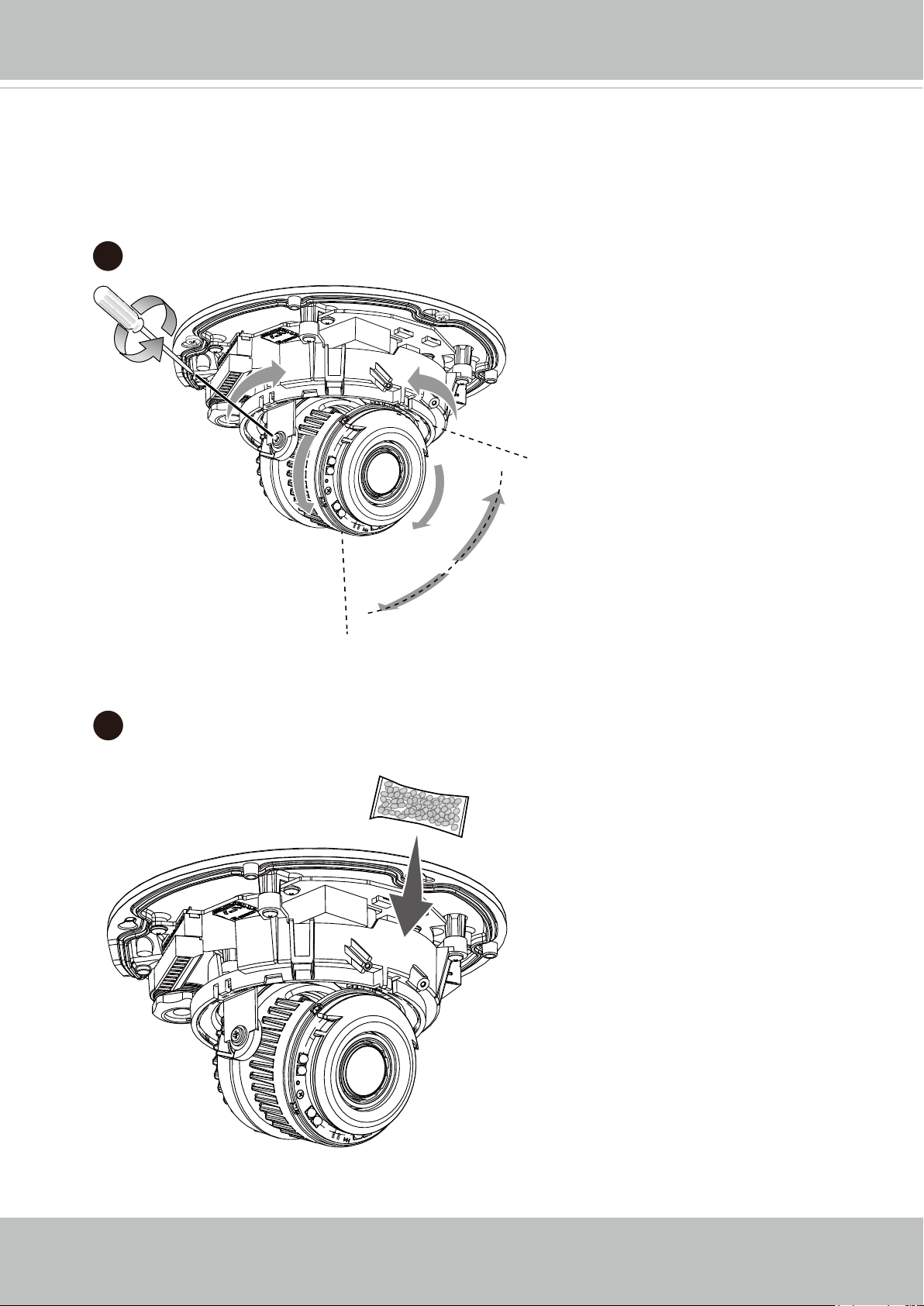
15. With a live view displayed on your laptop, adjust the zoom and focus to obtain an
optimal image. Check the live view to ensure the image is in focus.
The "T" models comes with motorized focus lens. Use the Auto Focus function in
rmware menu for best image.
15
350°
350°
16. Replace the desiccant bag on the camera.
16
60°
14 - User's Manual
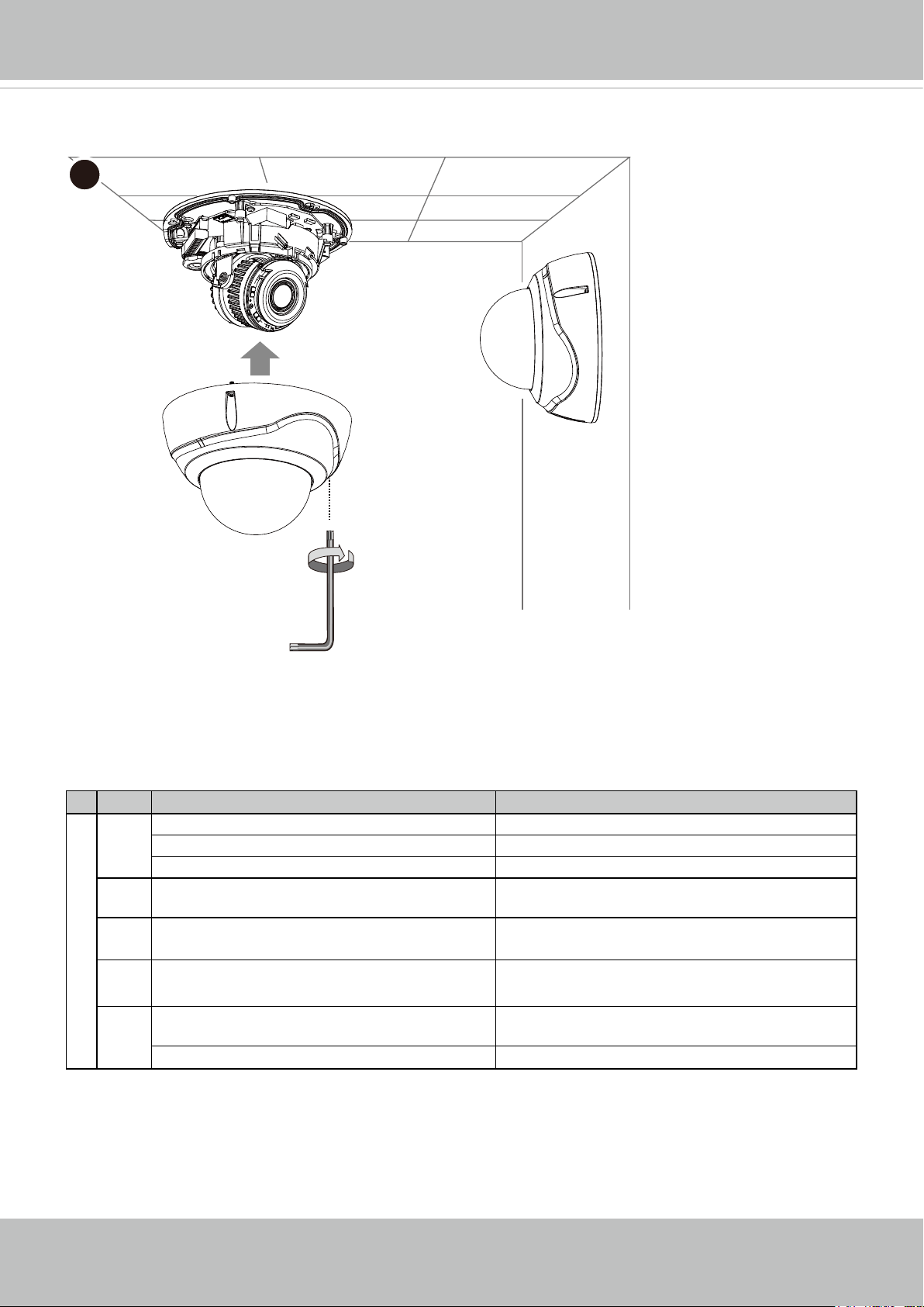
17. Align and install the dome cover.
17
VIVOTEK
18. Remove the protection membrane from the dome cover.
LED Denitions
Item LED status Description
LED De`nitions
1 Steady Red Powered and system booting, or network failed
Red LED off Power off
Green LED off Network is disconnected
2 Steady Red and Green LED blinks every 1
sec.
3 Green LED blinks every 1 sec. and RED
LED blinks consecutively every 0.15 sec.
4 Green and RED blink every 0.15 sec, Green
and RED light on, then blink again.
5 RED LED is on, Green LED blinks and RED
LED is constantly on.
Green and RED LEDs are constantly on. Status after a reset (network disconnected)
Connected to network
Upgrading rmware
Restoring defaults
Status after a reset (network connected)
User's Manual - 15

VIVOTEK
Hardware Reset
The reset button is used to reset the system or restore the factory default settings.
Sometimes resetting the system can return the camera to normal operation. If the system
problems remain after reset, restore the factory settings and install again.
Reset: Press the recessed reset button. Wait for the Network Camera to reboot.
Restore: Press and hold the reset button until the status LED rapidly blinks. Note that all
settings will be restored to factory default. Upon successful restore, the status LED will
blink green and red during normal operation.
SD/SDHC/SDXC Card Capacity
This network camera is compliant with SD/SDHC/SDXC 16GB / 8GB / 32GB / 64GB and
other preceding standard SD cards.
16 - User's Manual
Network Deployment
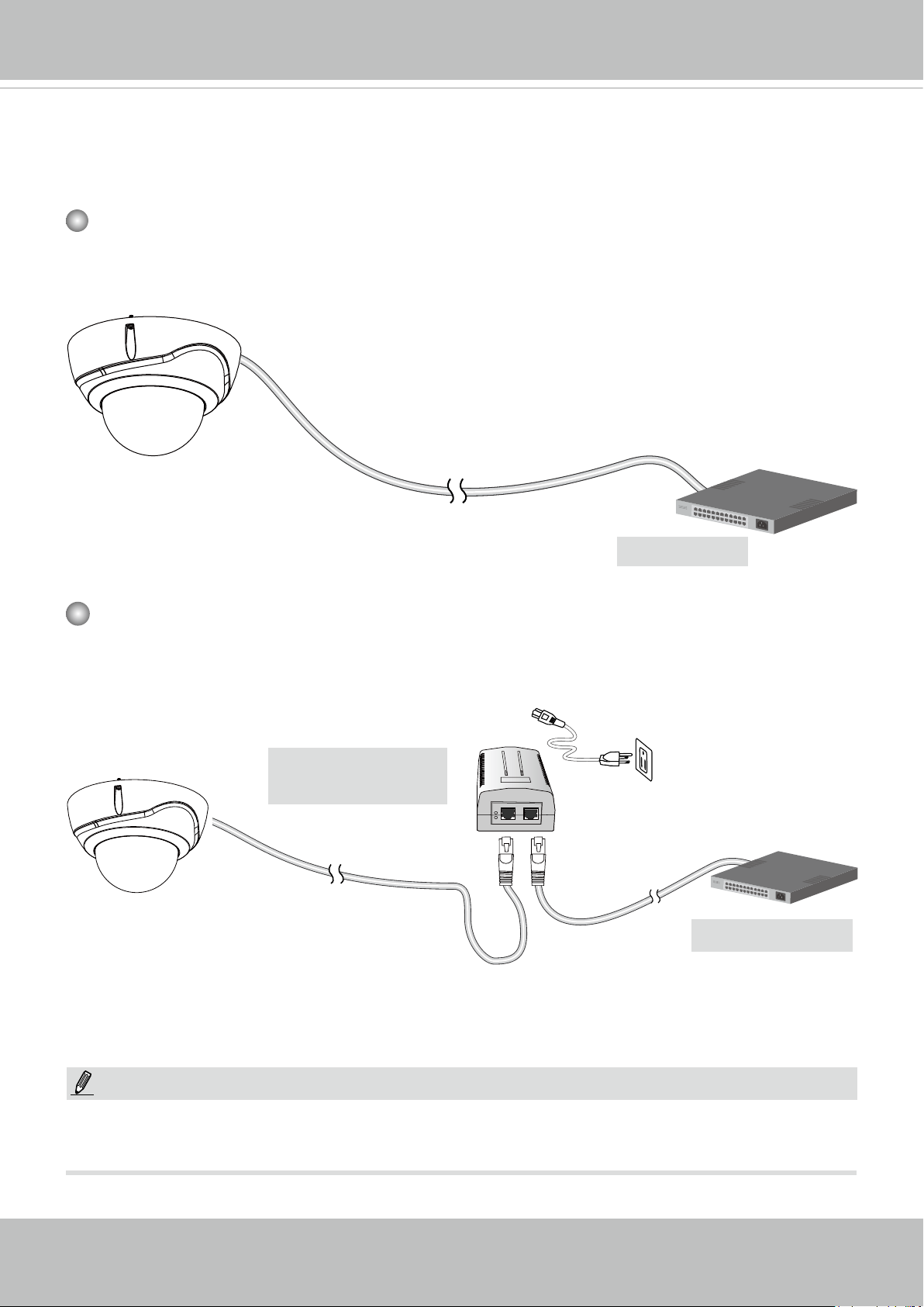
General Connection (PoE)
When using a PoE switch
The Network Camera is PoE-compliant, allowing transmission of power and data via a single Ethernet cable. Follow the illustration below to connect the Network Camera to a PoE
switch via an Ethernet cable.
802.3af
VIVOTEK
PoE Switch
When using a non-PoE switch
Use a PoE power injector (optional) to connect between the Network Camera and a nonPoE switch.
PoE Power Injector
(optional)
Non-PoE Switch
NOTE:
1. The camera is only to be connected to PoE networks without routing to outside plants.
2. For PoE connection, use only UL listed I.T.E. with PoE output.
User's Manual - 17
VIVOTEK
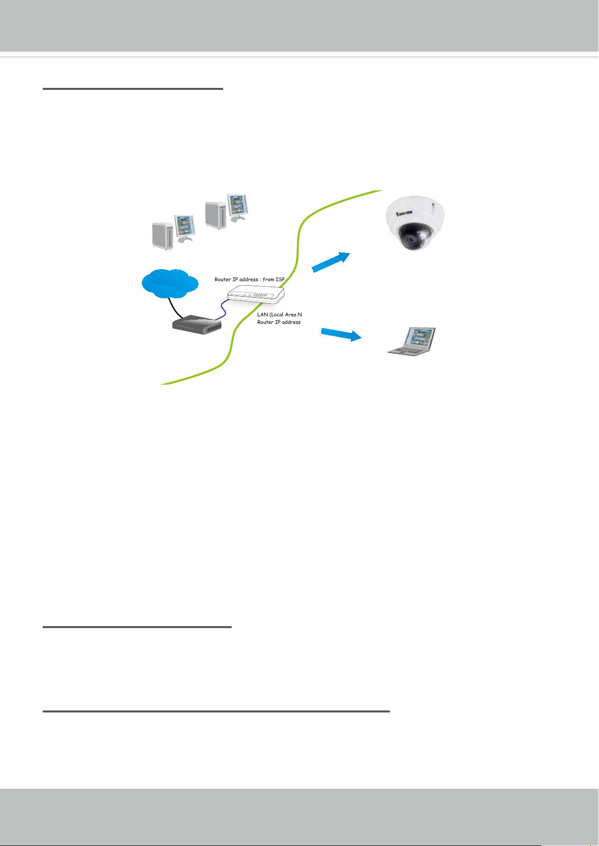
Internet connection via a router
Before setting up the Network Camera over the Internet, make sure you have a router and follow
the steps below.
1. Connect your Network Camera behind a router, the Internet environment is illustrated below.
Regarding how to obtain your IP address, please refer to Software Installation on page 20 for
details.
IP address : 192.168.0.3
Subnet mask : 255.255.255.0
Default router : 192.168.0.1
Internet
WAN (Wide Area Network )
Router IP address : from ISP
LINK
POWER
COLLISION
RECEIVE
1
2
PARTITION
3
4
5
LAN (Local Area Network)
Router IP address : 192.168.0.1
Cable or DSL Modem
IP address : 192.168.0.2
Subnet mask : 255.255.255.0
Default router : 192.168.0.1
2. In this case, if the Local Area Network (LAN) IP address of your Network Camera is
192.168.0.3, please forward the following ports for the Network Camera on the router.
■ HTTP port: default is 80
■ RTSP port: default is 554
■ RTP port for video: default is 5556
■ RTCP port for video: default is 5557
If you have changed the port numbers on the Network page, please open the ports
accordingly on your router. For information on how to forward ports on the router, please refer
to your router’s user’s manual.
3. Find out the public IP address of your router provided by your ISP (Internet Service Provider).
Use the public IP and the secondary HTTP port to access the Network Camera from the
Internet. Please refer to Network Type on page 77 for details.
Internet connection with static IP
Choose this connection type if you are required to use a static IP for the Network Camera.
Please refer to LAN setting on page 76 for details.
Internet connection via PPPoE (Point-to-Point over Ethernet)
Choose this connection type if you are connected to the Internet via a DSL Line. Please refer to
PPPoE on page 77 for details.
18 - User's Manual
VIVOTEK
Congure the router, virtual server or rewall, so that the router can forward any data coming into a precongured port number to a network camera on the private network, and
allow data from the camera to be transmitted to the outside of the network over the same
path.
From Forward to
122.146.57.120:8000 192.168.2.10:80
122.146.57.120:8001 192.168.2.11:80
... ...
When properly congured, you can access a camera behind the router using the HTTP
request such as: http://122.146.57.120:8000
If you change the port numbers on the Network conguration page, please open the ports
accordingly on your router. For example, you can open a management session with your
router to congure access through the router to the camera within your local network.
Please consult your network administrator for router conguration if you have troubles with
the conguration.
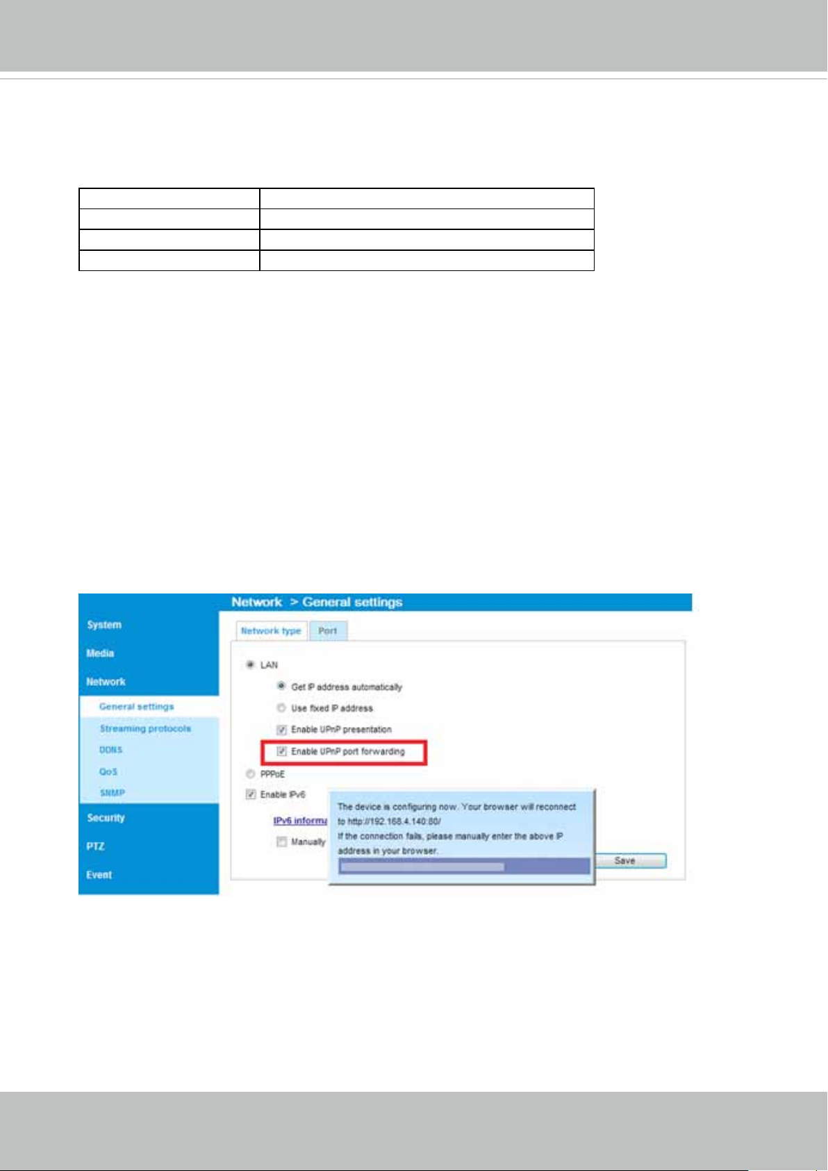
For more information with network conguration options (such as that of streaming ports),
please refer to Conguration > Network Settings. VIVOTEK also provides the automatic
port forwarding feature as an NAT traversal function with the precondition that your router
must support the UPnP port forwarding feature.
User's Manual - 19
VIVOTEK
Software Installation
Installation Wizard 2 (IW2), a software included in the product CD, helps you set up your
Network Camera on the LAN.
IW
1. Install IW2 under the Software Utility directory from the software CD.
Double-click the IW2 shortcut on your desktop to launch the program.
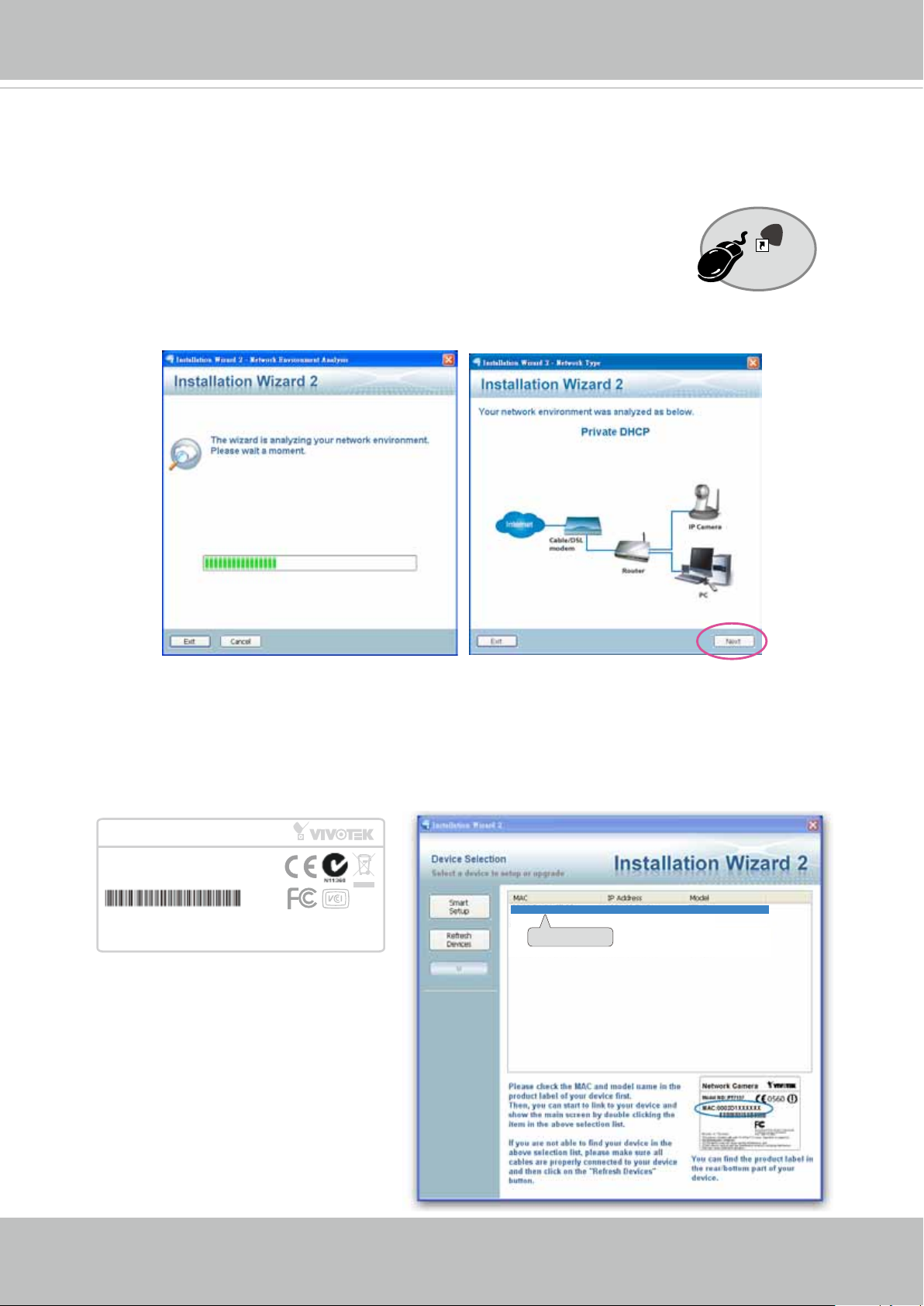
2. The program will conduct an analysis of your network environment.
After your network environment is analyzed, please click Next to continue the program.
2
Installation
Wizard 2
3. The program will search for all VIVOTEK network devices on the same LAN.
4. After a brief search, the installer window will prompt. Click on the MAC and model name
that matches the one printed on the product label. You can then double-click on the address
to open a management session with the Network Camera.
Network Camera
Model No: FD836BA
MAC:0002D1730202
This device complies with part 15 of the FCC rules. Operation is subject to the following two conditions:
(1)This device may not cause harmful interference, and
(2) this device must accept any interference received, including interference that may cause undesired operation.
Pat. 6,930,709
R o HS
Made in Taiwan
00-02-D1-73-02-02 192.168.5.151 FD836BA
0002D1730202
20 - User's Manual
VIVOTEK
Ready to Use
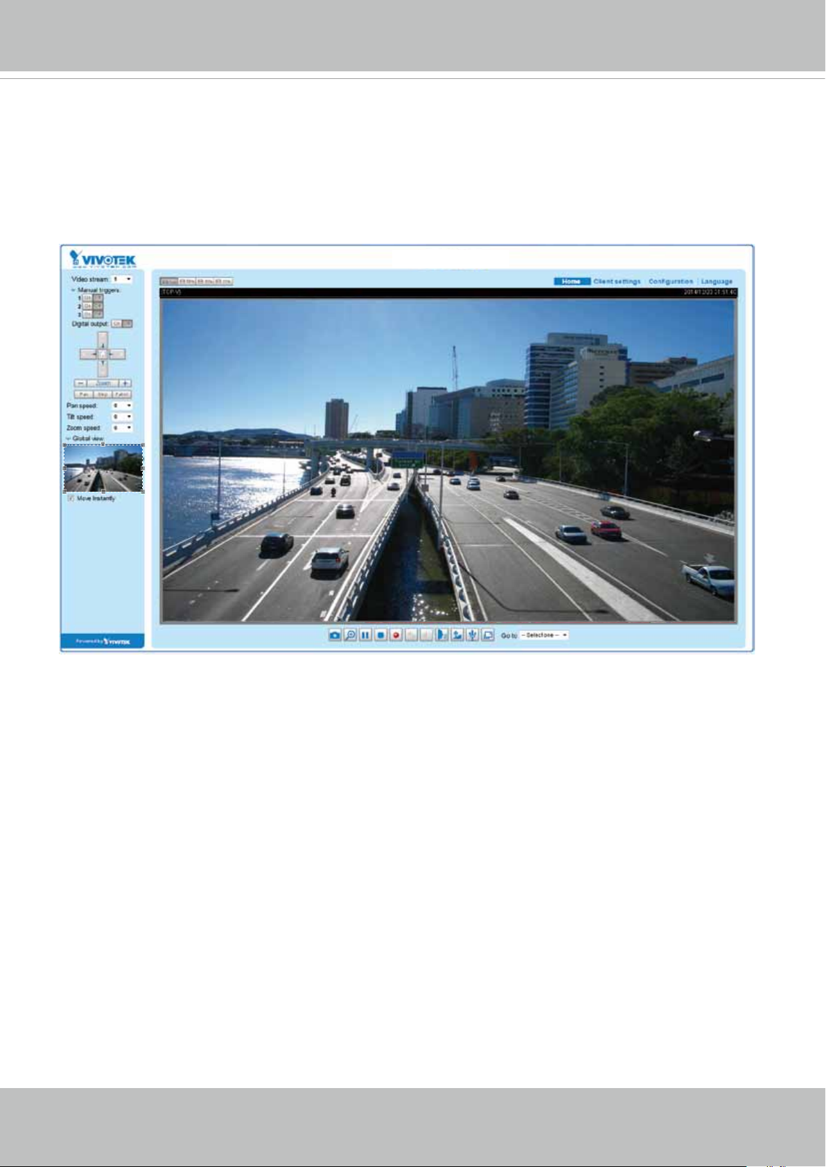
1. A browser session with the Network Camera should prompt as shown below.
2. You should be able to see live video from your camera. You may also install the 32-channel
recording software from the software CD in a deployment consisting of multiple cameras. For
its installation details, please refer to its related documents.
FD836BA
User's Manual - 21
VIVOTEK
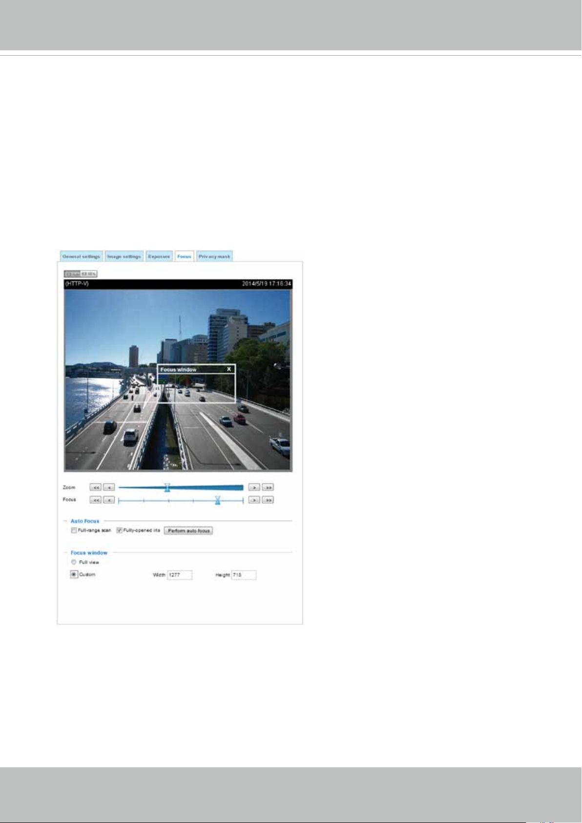
Auto Focus (for Motorized Lens Models only)
On the web console, visit the Conguration > Image > Focus window. Perform the Auto
Focus function for best image focus.
Focus here refers to the Remote Focus, applicable to Network Cameras that are equipped
with a stepping motor lens. The automated focus adjustment function eliminates the needs
to physically adjust camera focus. In an outdoor deployment consisting of a large number
of cameras, the auto focus function can be very helpful when these cameras become out
of focus after days or weeks of operation. And that can easily result from the effects of
natural forces, e.g., shrink and expand due to a wide range of operating temperatures and
the vibration caused by wind.
22 - User's Manual
VIVOTEK
Accessing the Network Camera
This chapter explains how to access the Network Camera through web browsers, RTSP players,
3GPP-compatible mobile devices, and VIVOTEK recording software.
Using Web Browsers
Use Installation Wizard 2 (IW2) to access the Network Cameras on LAN.
If your network environment is not a LAN, follow these steps to access the Netwotk Camera:
1. Launch your web browser (e.g., Microsoft
2. Enter the IP address of the Network Camera in the address eld. Press Enter.
3. Live video will be displayed in your web browser.
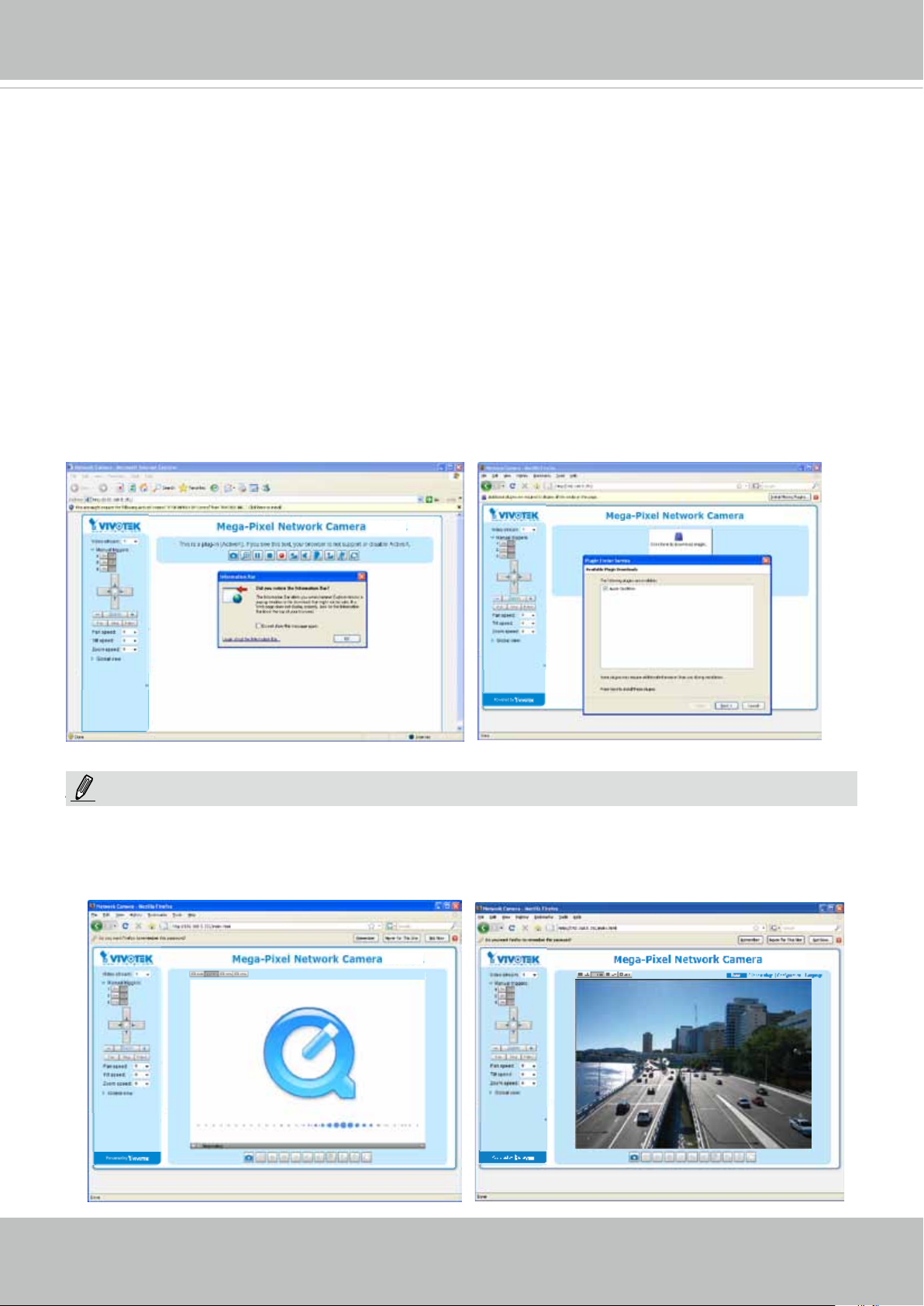
4. If it is the rst time installing the VIVOTEK network camera, an information bar will prompt as
shown below. Follow the instructions to install the required plug-in on your computer.
®
Internet Explorer or Mozilla Firefox).
NOTE:
NOTE
► For Mozilla Firefox or Chrome users, your browser will use Quick Time to stream the live
video. If you don’t have Quick Time on your computer, please download it rst, then launch
the web browser.
User's Manual - 23
VIVOTEK
► By default, the Network Camera is not password-protected. To prevent unauthorized access,
it is highly recommended to set a password for the Network Camera.
For more information about how to enable password protection, please refer to Security on
page 94.
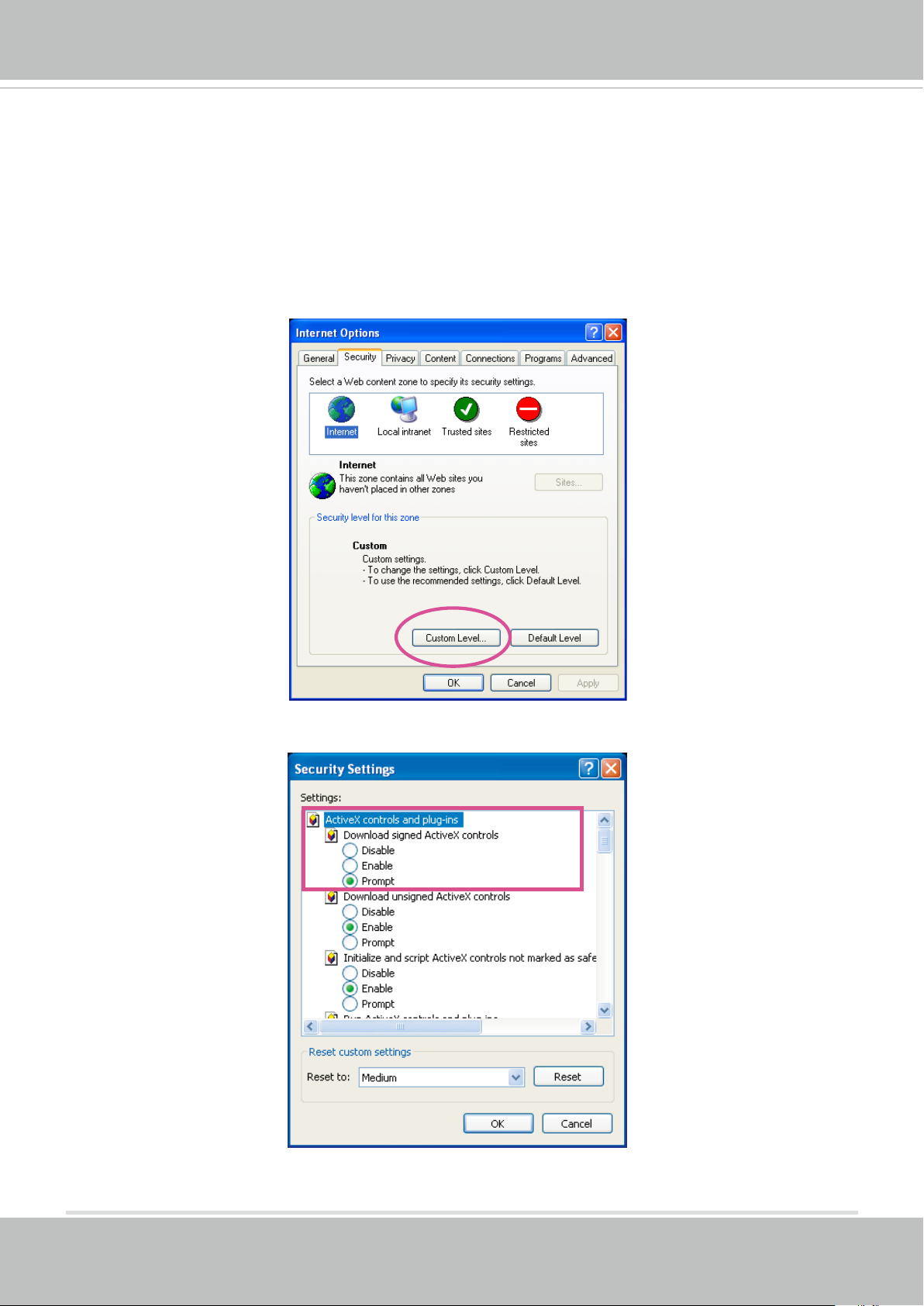
► If you see a dialog box indicating that your security settings prohibit running ActiveX
®
Controls, please enable the ActiveX
Controls for your browser.
®
1. Choose Tools > Internet Options > Security > Custom Level.
2. Look for Download signed ActiveX
®
controls; select Enable or Prompt. Click OK.
3. Refresh your web browser, then install the ActiveX
complete installation.
®
control. Follow the instructions to
24 - User's Manual
VIVOTEK
IMPORTANT:
Currently the Network Camera utilizes 32-bit ActiveX plugin. You CAN NOT open a
•
management/view session with the camera using a 64-bit IE browser.
If you encounter this problem, try execute the Iexplore.exe program from C:\Windows\
•
SysWOW64. A 32-bit version of IE browser will be installed.
On Windows 7, the 32-bit explorer browser can be accessed from here:
•
C:\Program Files (x86)\Internet Explorer\iexplore.exe
If you open a web session from the IW2 utility, a 32-bit IE browser will be opened.
•
Tips:
1. The onscreen Java control can malfunction under the following situations: A PC connects to different cameras that are using the same IP address (or the same camera
running different rmware versions). Removing your browser cookies will solve this
problem.
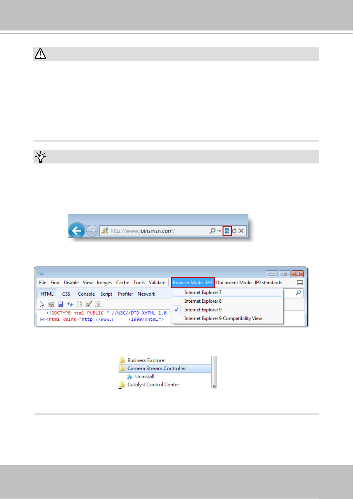
2. If you encounter problems with displaying the conguration menus or UI items, try disable the Compatibility View on IE8 or IE9.
You may also press the F12 key to open the developer tools utility, and then change the
Browser Mode to the genuine IE8 or IE9 mode.
• In the event of plug-in compatibility issues, you may try to uninstall the plug-in that was
previously installed.
User's Manual - 25
VIVOTEK
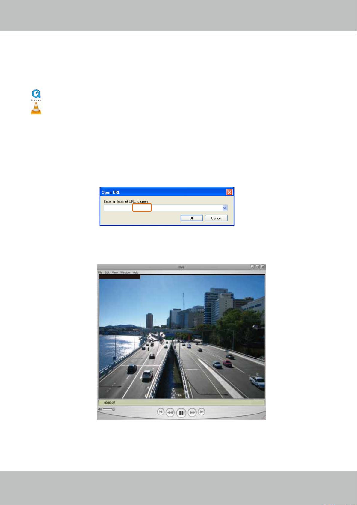
Using RTSP Players
To view the streaming media using RTSP players, you can use one of the following players that
support RTSP streaming.
Quick Time Player
VLC media player
VLC media player
1. Launch the RTSP player.
mpegable Player
2. Choose File > Open URL. A URL dialog box will pop up.
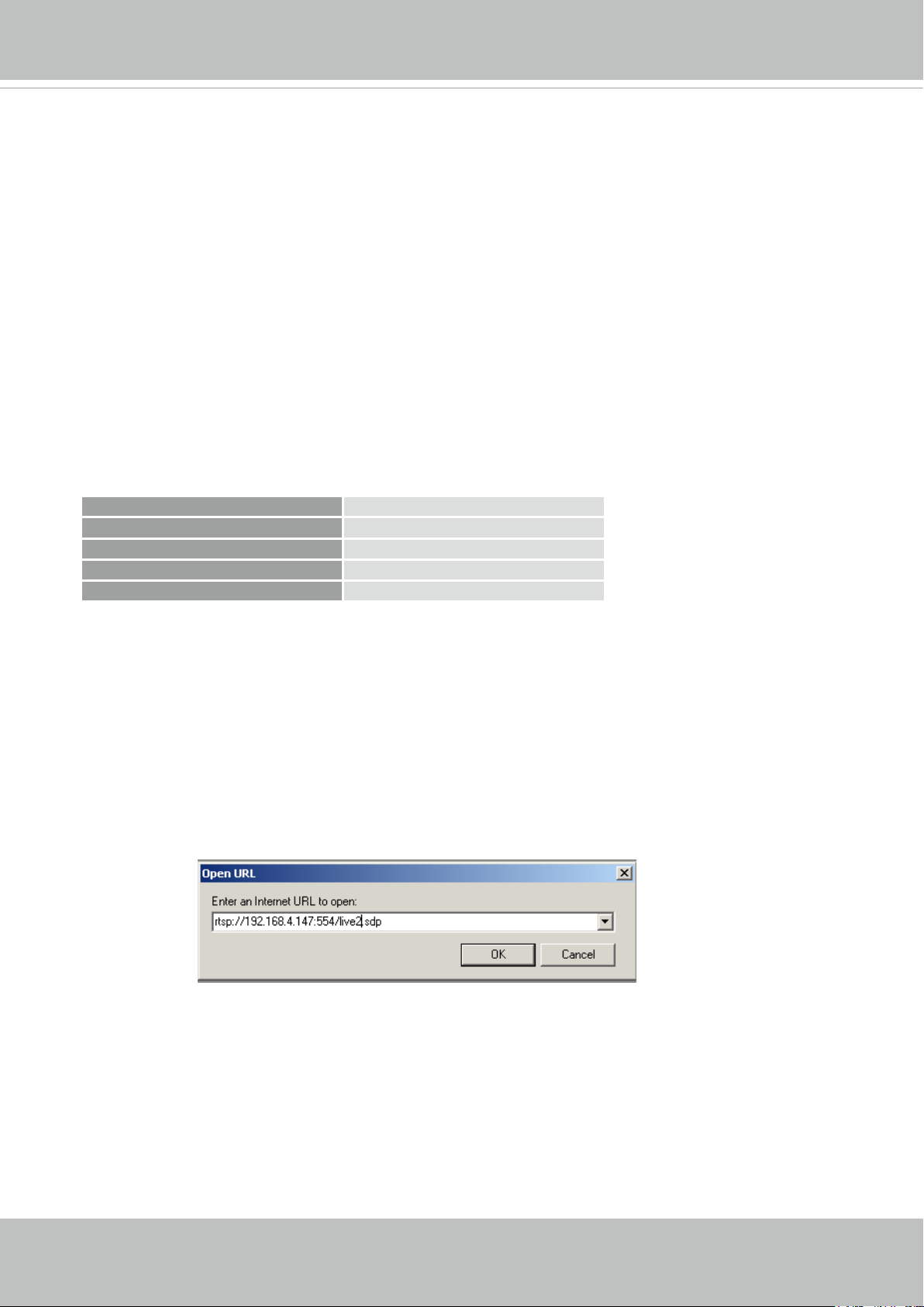
3. The address format is rtsp://<ip address>:<rtsp port>/<RTSP streaming access name for
pvPlayer
stream1 or stream2>
As most ISPs and players only allow RTSP streaming through port number 554, please set the
RTSP port to 554. For more information, please refer to RTSP Streaming on page 85.
For example:
rtsp://192.168.5.151:554/live.sdp
4. The live video will be displayed in your player.
For more information on how to configure the RTSP access name, please refer to RTSP
Streaming on page 85 for details.
Video 16:38:01 2012/01/25
26 - User's Manual
VIVOTEK
Video quality (Constant bit rate) 40kbps
Using 3GPP-compatible Mobile Devices
To view the streaming media through 3GPP-compatible mobile devices, make sure the Network
Camera can be accessed over the Internet. For more information on how to set up the Network
Camera over the Internet, please refer to Setup the Network Camera over the Internet on page
17.
To utilize this feature, please check the following settings on your Network Camera:
1. Because most players on 3GPP mobile phones do not support RTSP authentication, make
sure the authentication mode of RTSP streaming is set to disable.
For more information, please refer to RTSP Streaming on page 85.
2. As the the bandwidth on 3G networks is limited, you will not be able to use a large video size.
Please set the video streaming parameters as listed below.
For more information, please refer to Stream settings on page 66.
Video Mode H.264
Frame size 176 x 144
Maximum frame rate 5 fps
Intra frame period 1S
3. As most ISPs and players only allow RTSP streaming through port number 554, please set
the RTSP port to 554. For more information, please refer to RTSP Streaming on page 85.
4. Launch the player on the 3GPP-compatible mobile devices (e.g., Quick Time).
5. Type the following URL commands into the player.
The address format is rtsp://<public ip address of your camera>:<rtsp port>/<RTSP streaming
access name for stream # with small frame size and frame rate>.
For example:
You can configure Stream #2 into the suggested stream settings as listed above for live
viewing on a mobile device.
User's Manual - 27
VIVOTEK
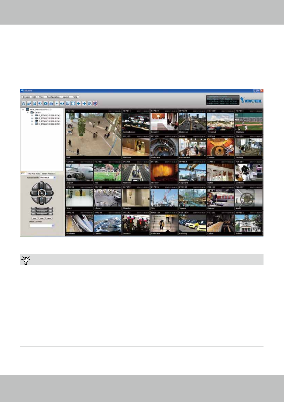
Using VIVOTEK Recording Software
The product software CD also contains a VAST recording software, allowing simultaneous
monitoring and video recording for multiple Network Cameras. Please install the recording
software; then launch the program to add the Network Camera to the Channel list. For detailed
information about how to use the recording software, please refer to the user’s manual of the
software or download it from http://www.vivotek.com.
Tips:
1. If you forget the root (administrator) password for the camera, you can restore the camera
defaults by pressing the reset button for longer than 5 seconds.
2. If DHCP is enabled in your network, and the camera cannot be accessed, run the IW2 utility
to search the network. If the camera has been congured with xed IP that does not comply
with your local network, you may see its default IP 169.254.x.x. If you still cannot find the
camera, you can restore the camera to its factory defaults.
3. If you change your network parameters, e.g., added a camera via a connection to a LAN
card, re-start the IW2 utility.
28 - User's Manual
VIVOTEK
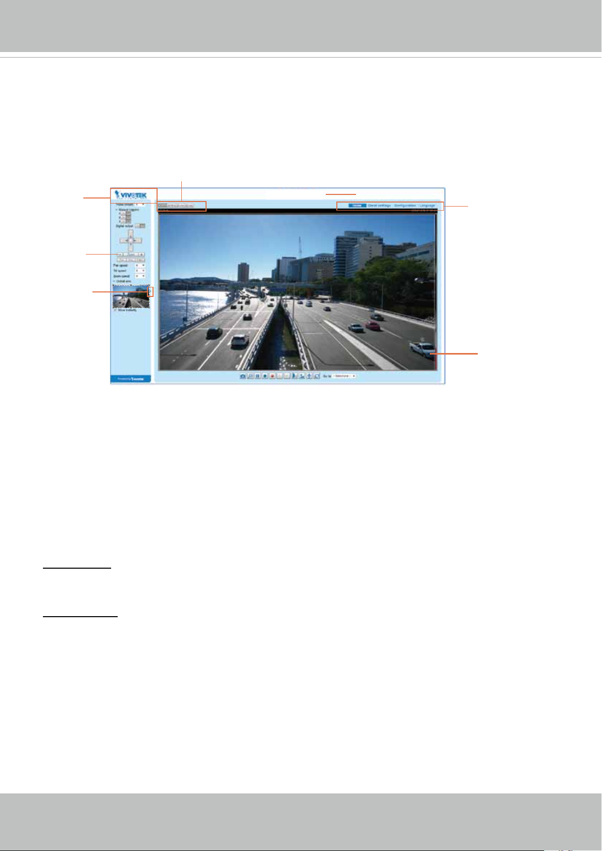
Main Page
This chapter explains the layout of the main page. It is composed of the following sections:
VIVOTEK INC. Logo, Host Name, Camera Control Area, Configuration Area, Menu, and Live
Video Window.
Resize Buttons
VIVOTEK INC.
Logo
Camera Control
Area
Hide Button
FD836BA
Host Name
Configuration
Area
Live View Window
VIVOTEK INC. Logo
Click this logo to visit the VIVOTEK website.
Host Name
The host name can be customized to t your needs. The name can be changed especially there are many
cameras in your surveillance deployment. For more information, please refer to System on page 40.
Camera Control Area
Video Stream: This Network Camera supports multiple streams (streams 1 and 2) simultaneously. You
can select any of them for live viewing. For more information about multiple streams, please refer to page
66 for detailed information.
Manual Trigger: Click to enable/disable an event trigger manually. Please congure an event setting on
the Application page before you enable this function. A total of 3 event conguration can be congured.
For more information about event setting, please refer to page 110. If you want to hide this item on
the homepage, please go to Configuration> System > Homepage Layout > General settings >
Customized button to deselect the “show manual trigger button” checkbox.
User's Manual - 29
VIVOTEK
H.264 Protocol and Media Options
Conguration Area
Client Settings: Click this button to access the client setting page. For more information, please refer to
Client Settings on page 34.
Conguration: Click this button to access the conguration page of the Network Camera. It is suggested
that a password be applied to the Network Camera so that only the administrator can configure the
Network Camera. For more information, please refer to Conguration on page 39.
Language: Click this button to choose a language for the user interface. Language options are available
in: English, Deutsch, Español, Français, Italiano,
日本語
, Português,
簡体中文
, and
繁體中文
. Please
note that you can also change a language on the Conguration page; please refer to page 39.
Hide Button
You can click the hide button to hide or display the control panel.
Resize Buttons
:
Click the Auto button, the video cell will resize automatically to t the monitor.
Click 100% is to display the original homepage size.
Click 50% is to resize the homepage to 50% of its original size.
Click 25% is to resize the homepage to 25% of its original size.
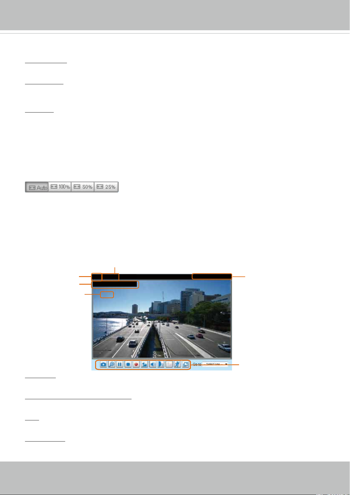
Live Video Window
■ The following window is displayed when the video mode is set to H.264:
Video Title
Title and Time
Zoom Indicator
Video (TPC-AV)
Video 17:08:56 2015/03/25
x4.0
Video Title: The video title can be congured. For more information, please refer to Video Settings on
page 52.
H.264 Protocol and Media Options: The transmission protocol and media options for H.264 video
streaming. For further conguration, please refer to Client Settings on page 34.
2015/03/25 17:08:56
Time
Video Control Buttons
Time: Display the current time. For further conguration, please refer to Media > Image > Genral settings
on page 52.
Title and Time: The video title and time can be stamped on the streaming video. For further conguration,
please refer to Media > Image > General settings on page 57.
30 - User's Manual
 Loading...