


IP8160-W
Table of contents
 Loading...
Wireless Cube
IP8160-W
Network Camera
User’s Manual
2MP • 8M IR • Smart Stream II • AEC
WiFi • Compact Size
Rev. 1.1:
Rev. 1.0

VIVOTEK
Table of Contents
Overview
Revision History ...............................................................................................................................................3
Read Before Use ..............................................................................................................................................4
Package Contents ............................................................................................................................................4
Symbols and Statements in this Document ......................................................................................................5
Physical Description .........................................................................................................................................5
Hardware Installation ........................................................................................................................................7
Software Installation .......................................................................................................................................19
Ready to Use ..................................................................................................................................................20
Accessing the Network Camera
Using Web Browsers ......................................................................................................................................21
Using RTSP Players .......................................................................................................................................24
Using 3GPP-compatible Mobile Devices ........................................................................................................25
Using VIVOTEK Recording Software .............................................................................................................26
Main Page
Client Settings
Conguration
System > General settings .............................................................................................................................38
System > Homepage layout ..........................................................................................................................40
System > Logs ...............................................................................................................................................43
System > Parameters ....................................................................................................................................45
System > Maintenance ...................................................................................................................................46
Media > Image .............................................................................................................................................50
Media > Video ................................................................................................................................................59
Media > Video ................................................................................................................................................60
Media > Audio.................................................................................................................................................68
Network > General settings ............................................................................................................................69
Network > Streaming protocols ....................................................................................................................76
Network > SNMP (Simple Network Management Protocol) ...........................................................................84
Network > FTP ...............................................................................................................................................85
Wireless > WLAN ...........................................................................................................................................86
Wireless > WPS .............................................................................................................................................88
Security > User accounts ...............................................................................................................................89
Security > HTTPS (Hypertext Transfer Protocol over SSL) .................................................................90
Security > Access List ..................................................................................................................................97
PTZ > PTZ settings ......................................................................................................................................100
Event > Event settings..................................................................................................................................104
Applications > Motion detection....................................................................................................................118
Applications > Tampering detection .............................................................................................................121
Applications > Audio detection ...................................................................................................................122
Applications > Package management - a.k.a., VADP (VIVOTEK Application Development Platform) .......124
Recording > Recording settings ..................................................................................................................127
Local storage > SD card management .........................................................................................................132
Local storage > Content management .........................................................................................................133
..............................................................................................................................................................
....................................................................................................................
......................................................................................................................................................
..................................................................................................................................................
....................................................................................................................................................
3
21
27
32
37
2 - User's Manual

VIVOTEK
Appendix
URL Commands for the Network Camera ................................................................................................ 136
Technical Specications ...........................................................................................................................342
Technology License Notice ....................................................................................................................... 344
Electromagnetic Compatibility (EMC) .......................................................................................................347
....................................................................................................................................................
136
Overview
VIVOTEK’s IP8160/IP8160-W is a stylish 2-megapixel cube network camera specifically
designed for small-scale retail security applications. With a resolution of 1920x1080 at
30 fps, a removable IR-cut lter and built-in IR illuminators effective up to 8 meters, this
remarkable camera provides users with superior image quality around the clock.
When coupled with VIVOTEK’s Smart Stream II technology, the IP8160/IP8160-W can
reduce both bandwidth and storage consumption by up to 50%* while retaining the same
superb image quality as a Full HD camera.
Further, the camera supports two-way audio, and employs Acoustic Echo Cancellation
(AEC) to greatly enhance audio quality and provide a clearer, smoother auditory image.
VIVOTEK provides two easy-to install options for this compact camera; the IP8160-W
boasts a 802.11b/g/n compatible wireless connection, and the IP8160 is designed for
Power over Ethernet (PoE) functionality, making setup of these two powerful cameras both
quick and simple.
* Depending on scene monitored.
Revision History
■ Rev. 1.0: Initial release.
■ Rev. 1.1: Removed the description for 802.1x, CoS, and QoS conguration.
User's Manual - 3

VIVOTEK
Read Before Use
The use of surveillance devices may be prohibited by law in your country. The Network Camera
is not only a high-performance web-ready camera but can also be part of a exible surveillance
system. It is the user’s responsibility to ensure that the operation of such devices is legal before
installing this unit for its intended use.
It is important to first verify that all contents received are complete according to the Package
Contents listed below. Take note of the warnings in the Quick Installation Guide before the Network
Camera is installed; then carefully read and follow the instructions in the Installation chapter to
avoid damage due to faulty assembly and installation. This also ensures the product is used
properly as intended.
The Network Camera is a network device and its use should be straightforward for those who
have basic networking knowledge. It is designed for various applications including video sharing,
general security/surveillance, etc. The Configuration chapter suggests ways to best utilize the
Network Camera and ensure proper operations. For creative and professional developers, the URL
Commands of the Network Camera section serves as a helpful reference to customizing existing
homepages or integrating with the current web server.
Package Contents
■ IP8160-W and camera stand
■ Screws and anchors
■ Power adaptor
■ Quick Installation Guide
NOTE:
Use the camera only with a DC power supply that is UL listed, and limited power
•
source (LPS) certied. The power supply should bear the UL listed and LPS marks.
The power supply must also meet any safety and compliance requirements for the
country of use.
When installing the camera, do not use excessive force.
•
< 10 kgf-cm
4 - User's Manual
Symbols and Statements in this Document
i
INFORMATION: provides important messages or advices that might help prevent
inconvenient or problem situations.
NOTE: Notices provide guidance or advices that are related to the functional integrity of
the machine.
Tips: Tips are useful information that helps enhance or facilitae an installation, function,
or process.
WARNING: or IMPORTANT:: These statements indicate situations that can be
dangerous or hazardous to the machine or you.
Electrical Hazard: This statement appears when high voltage electrical hazards might
occur to an operator.
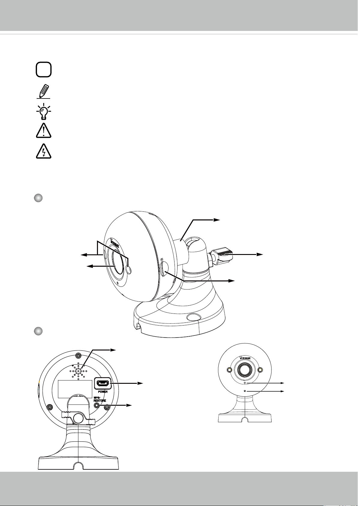
Physical Description
VIVOTEK
Front View
IR LED
Lens
Rear View
Fastening ring
Fastening handle
MicroSD/SDHC/SDXC Card slot
Speaker
Micro USB power
socket
WPS / Reset / Restore
button
Microphone
Status LED
User's Manual - 5
VIVOTEK
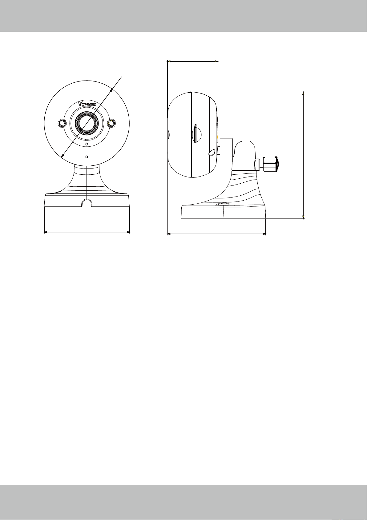
Dimension Drawing
38.85
n 66
97.5
66.01
75.9
6 - User's Manual
VIVOTEK
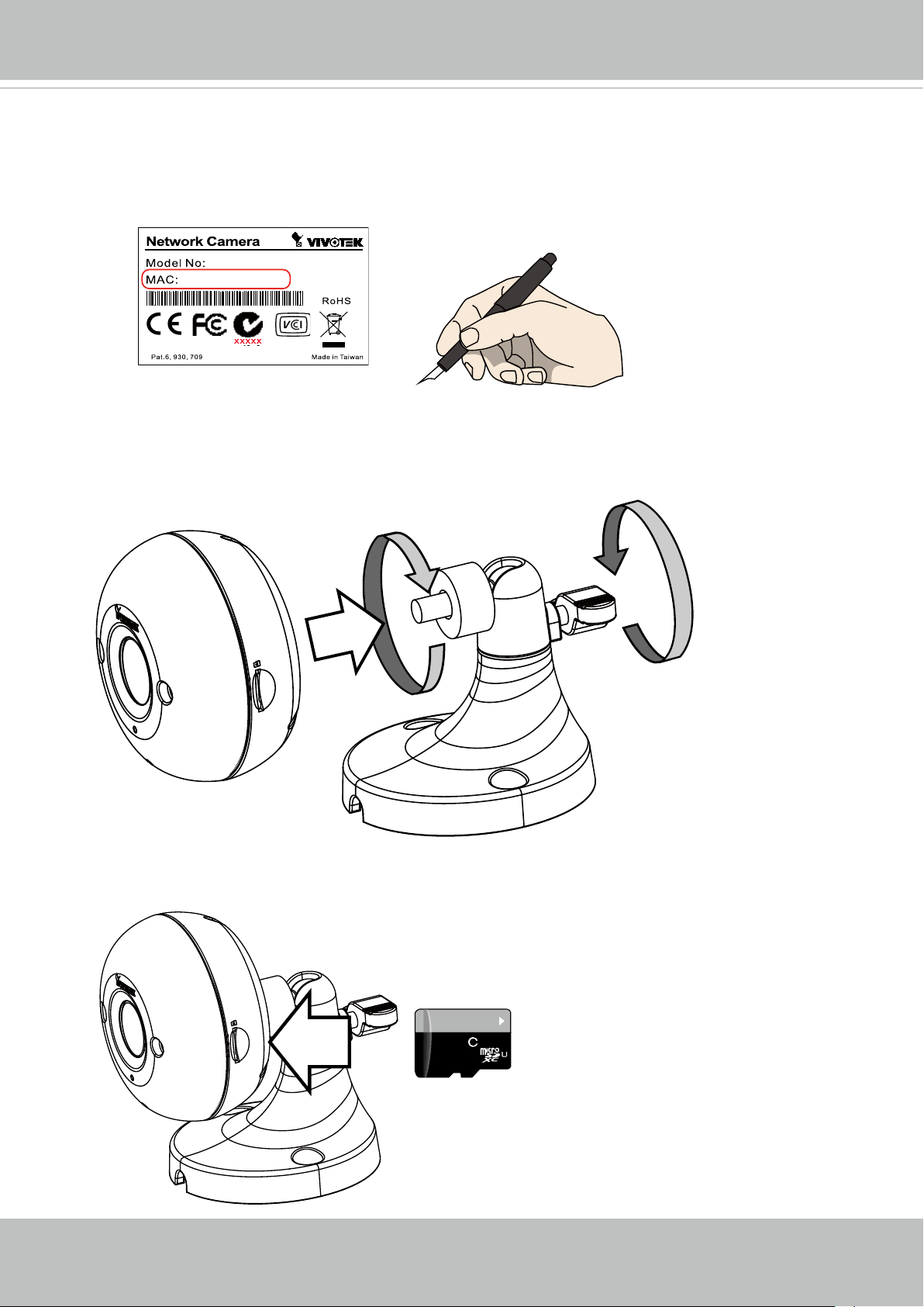
Hardware Installation
1. Jot down the camera's MAC address for later reference.
XXXXXX
0002D10766AD
2. Install lthe camera to bracket by rotating and fastening the fastening ring. Tilt the camera
to a preferred shooting angle, and then fasten the handle.
3. Install a MicroSD card if onboard storage is preferred.
10
64
GB
1
I
User's Manual - 7
VIVOTEK
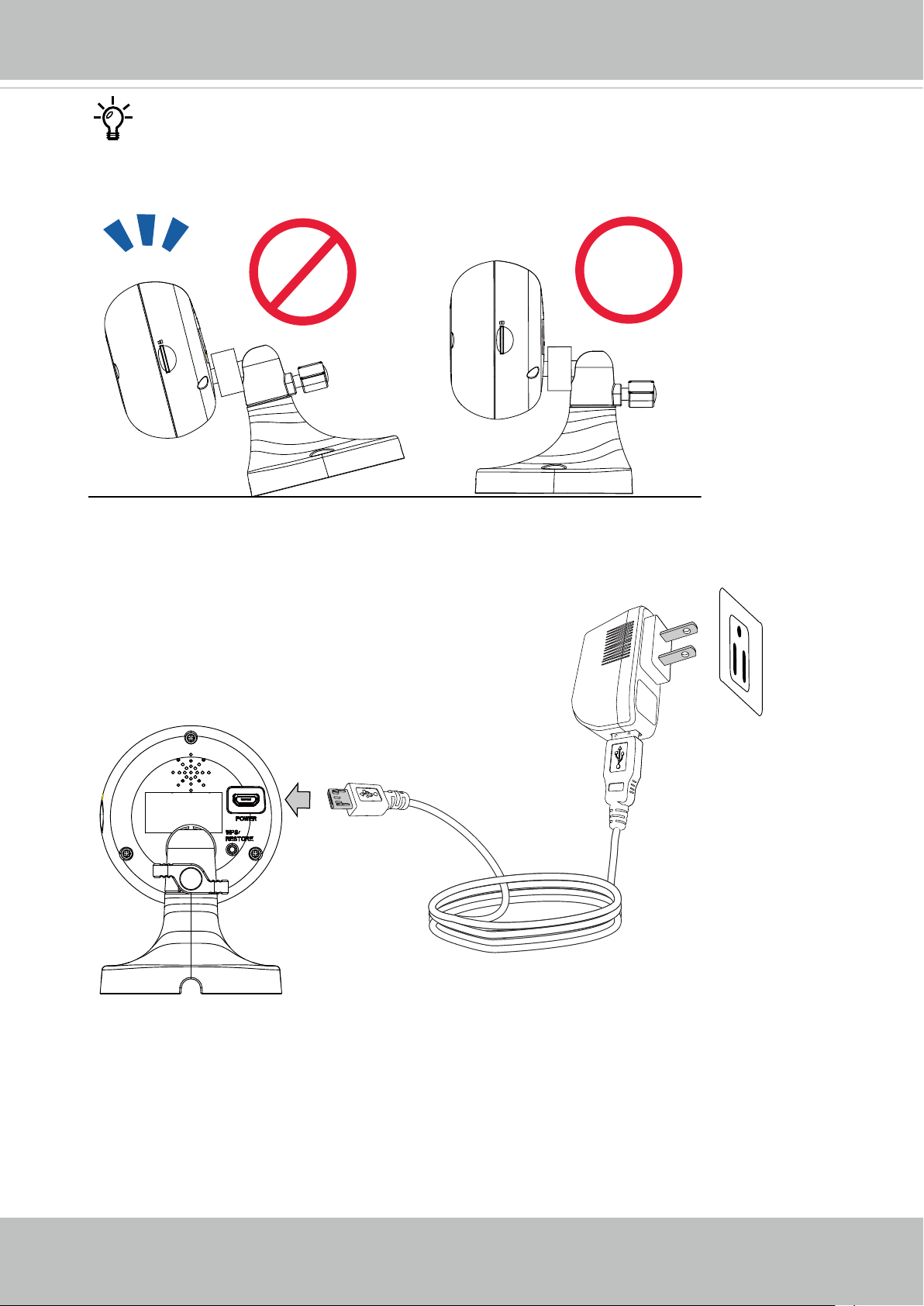
Note that the longer edge of the camera stand should be oriented to the camera side.
4. Connect the included power between the camera and the power mains.
8 - User's Manual
VIVOTEK
IMPORTANT:
Refer to the functional description and LED denitions below when conguring the camera.
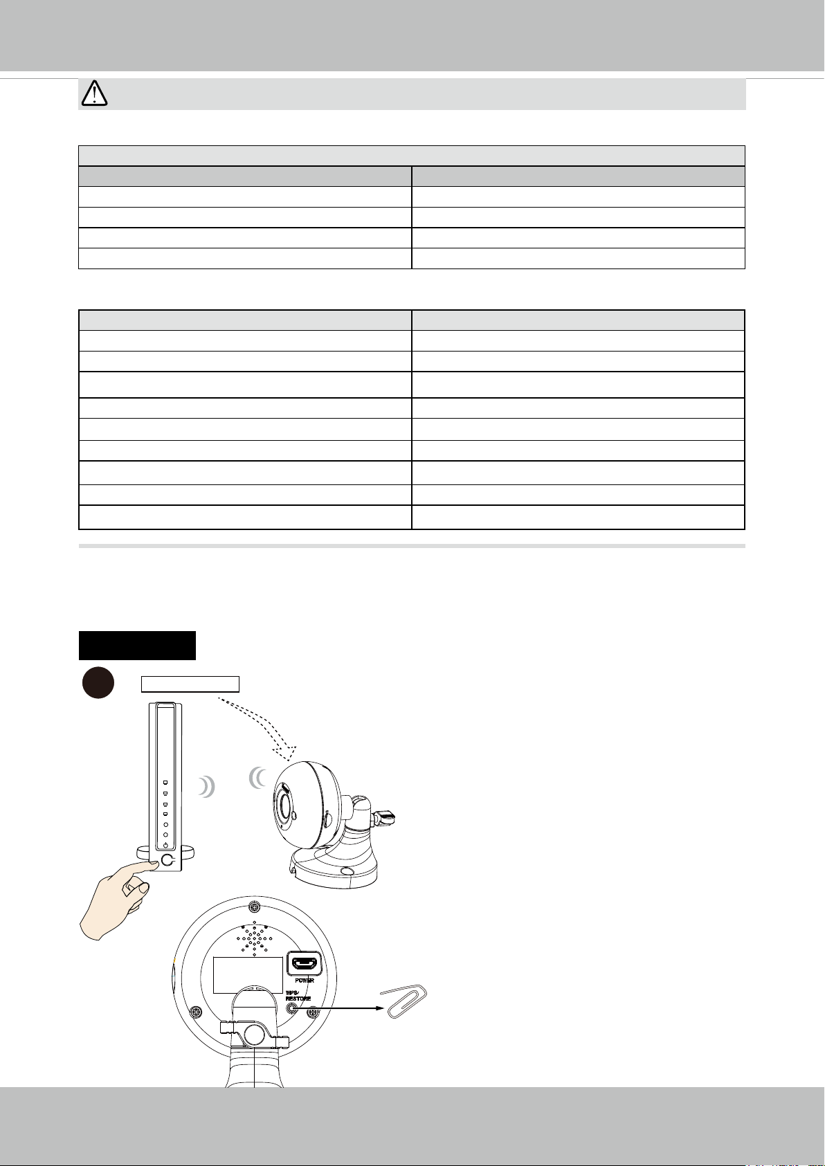
WPS Button Usage
Function LED Behavior
- White - operating in AP mode (default status).
Reset - press less than 3 seconds, Off then Red, then White.
WPS - press 3 to 5 secs, Flashing Blue for 2 mins, then Red, then Green.
Restore default - press longer than 7 secs. Flashing Red and Green
LED Denitions
LED Color Indication
Steady Red Power on and system booting
All LED off Power off
Blink Red / Green every 0.15 sec Upgrading F/W
Blink Orange every 0.15 sec Restoring default
Blink Green every 1 sec Wireless AP linked
Blink Blue every 0.15 sec WPS searching
Blink White every 0.5 sec Operating in AP mode
Steady Red Network Failed
Blink Red / Green every 1 sec Connected to network
5. Connecting to network. There are 3 different ways to connect the camera to a wireless
network.
A: WPS
A-1
WEP or WPA-PSK
WPS
AP
> 3secs
A-1. Use a straightened paper clip to
press the WPS button for 3 to 5 seconds.
A-2. Press the WPS button on your
wireless AP (router). Some router/
AP have a virtual button on their
management software instead. Refer
to your AP's documentation for details
using its WPS function.
When WPS conguration is done,
wireless connectivity will be established
and the security encryption, such as
WEP or WPA-PSK, will be synchronized
with the AP. Install and use VIVOTEK's
IW2 utility to nd the camera. By default,
the camera's rmware uses the DHCP
client mode.
WPS
User's Manual - 9
VIVOTEK
NOTE:
1. WPS may not work if your AP is congured with a "hidden" SSID.
2. If no WPS-enabled AP is detected, the camera will repeat trying to connect by every 20
seconds. If the camera still can not detect an AP after 2 minutes, the wireless setup will
be cancelled.
3.If a camera is assigned with a fiex IP outside the AP's network segment, wireless
conguration will fail.
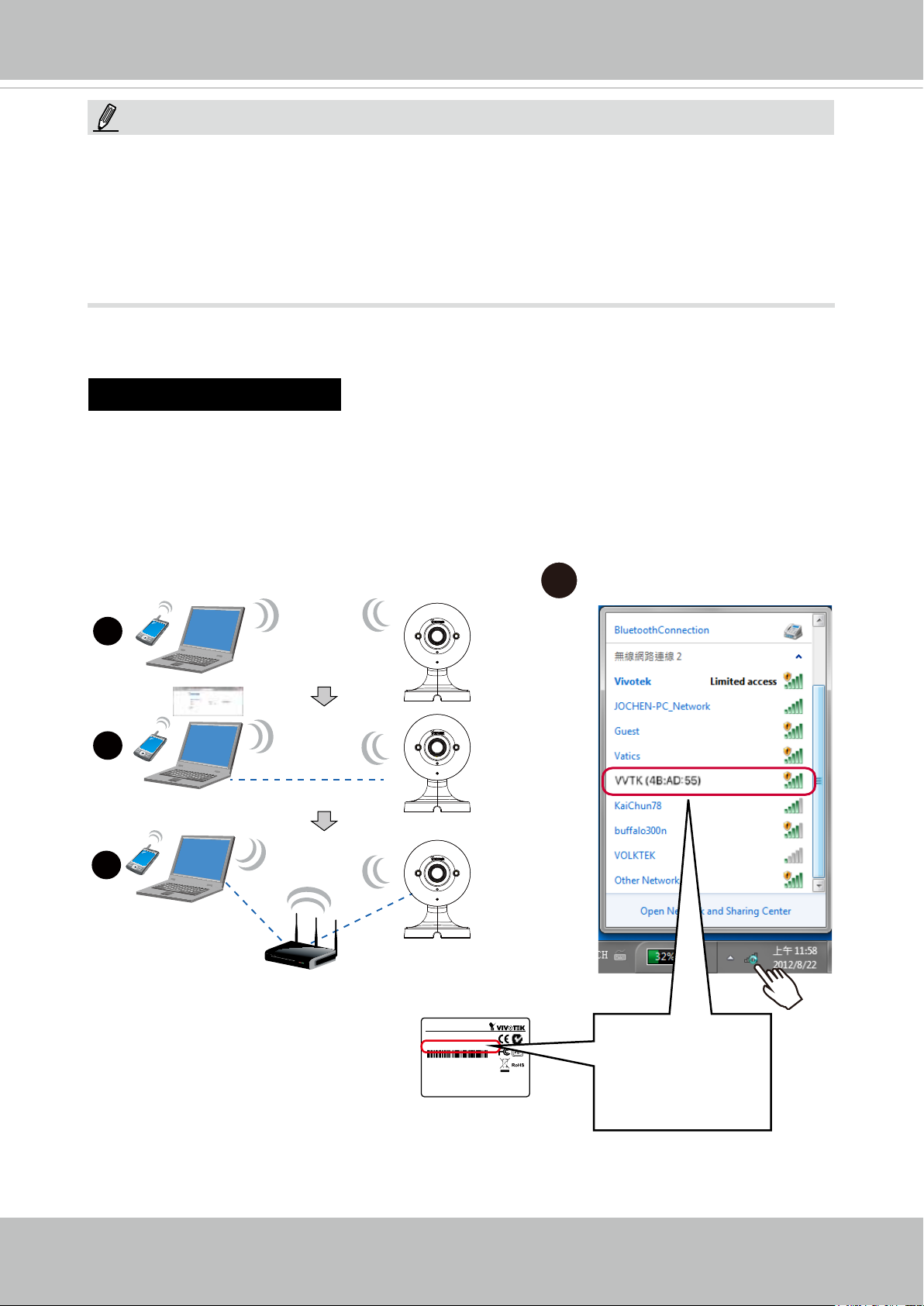
B: WiFi w/o WPS
B-1. When your device has wireless connectivity, e.g., a notebook. Use it to connect
search and connect the camera. The camera comes using the AP mode as the default.
B-2. Search your wireless network. You should be able to nd the camera displayed as
"VVTK (3 octets of the MAC address)."
1
2
3
AP
AP mode
Client mode
Network Camera
Model No: XXXXXX
MAC: 0002D14BAD55
This device complies with part 15 of the FCC Rules. Operation is subject to
the following two conditions:
(1) this device may not cause harmful interference, and
(2) this device must accept any interference received, including interference
that may cause undesired operation.
Pat. 6,930,709
Made in Taiwan
B-1
VIVOTEK (1C:CC)
MAC
4B:AD:55
10 - User's Manual
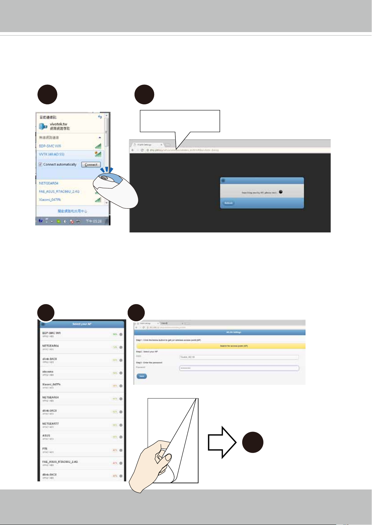
B-2. Select the camera and right-click to display the Connect button. Click to connect.
B-3. Open a web browser, enter the camera's default IP: 192.168.1.1.
B-2 B-3
192.168.1.1
VIVOTEK
B-4. The camera will search for the other APs within the network. Select an AP you prefer
your camera will connect to.
B-5. Enter the credentials for log in to your AP. Please move to Step 6.
B-4 B-5
6
User's Manual - 11
VIVOTEK
C:
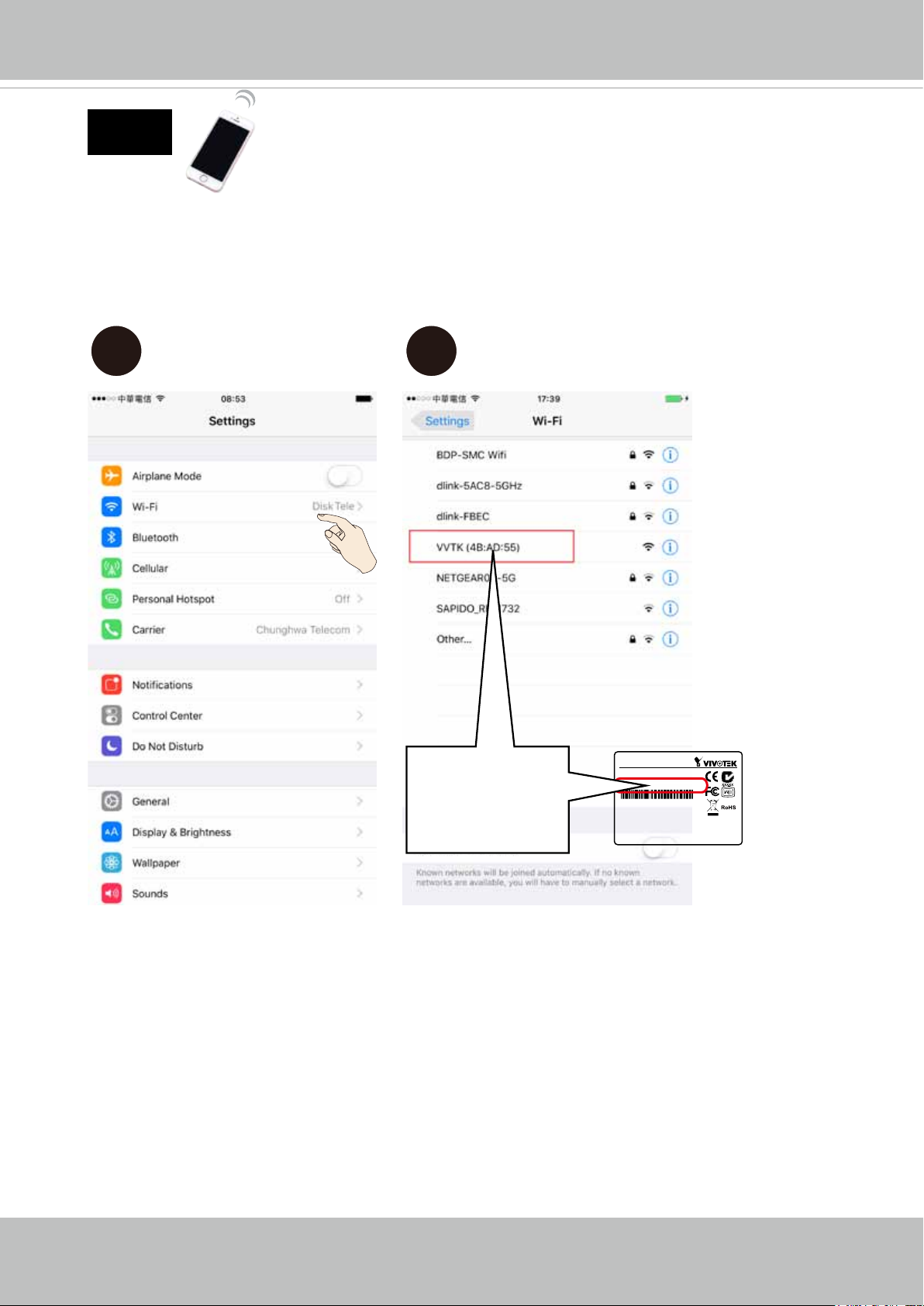
C-1. You can also use your cell phone to connect the camera. Open your Wi-Fi setting
page.
C-2. You should be able to nd the camera displayed as "VVTK (last 3 octets of the MAC
address)." Identify the camera using its MAC address.
C-1 C-2
MAC
4B:AD:55
Network Camera
Model No: XXXXXX
MAC: 0002D14BAD55
This device complies with part 15 of the FCC Rules. Operation is subject to
the following two conditions:
(1) this device may not cause harmful interference, and
(2) this device must accept any interference received, including interference
that may cause undesired operation.
Pat. 6,930,709
Made in Taiwan
12 - User's Manual
VIVOTEK
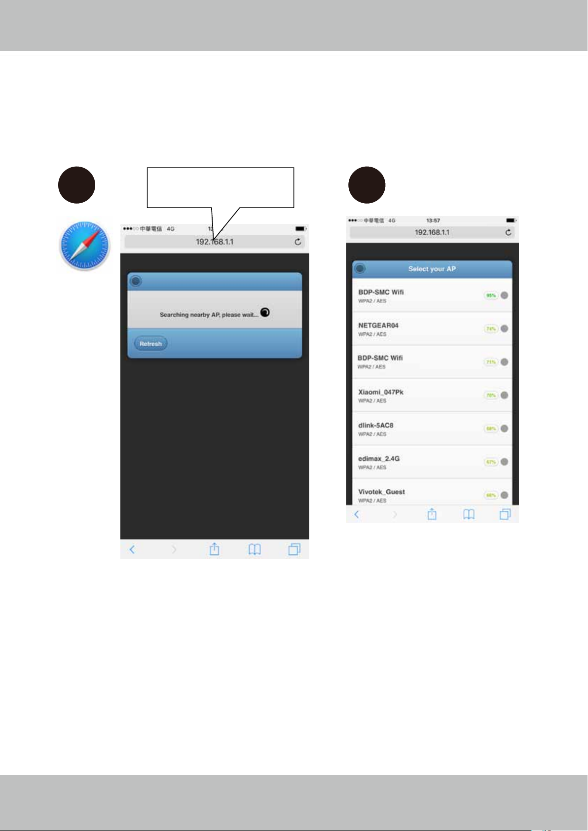
C-3. Open a web browser window. Enter the camera's default IP: 192.168.1.1.
C-4. The camera will search for the other APs within the network. Select an AP you prefer
your camera will connect to.
C-3
192.168.1.1
C-4
User's Manual - 13
VIVOTEK
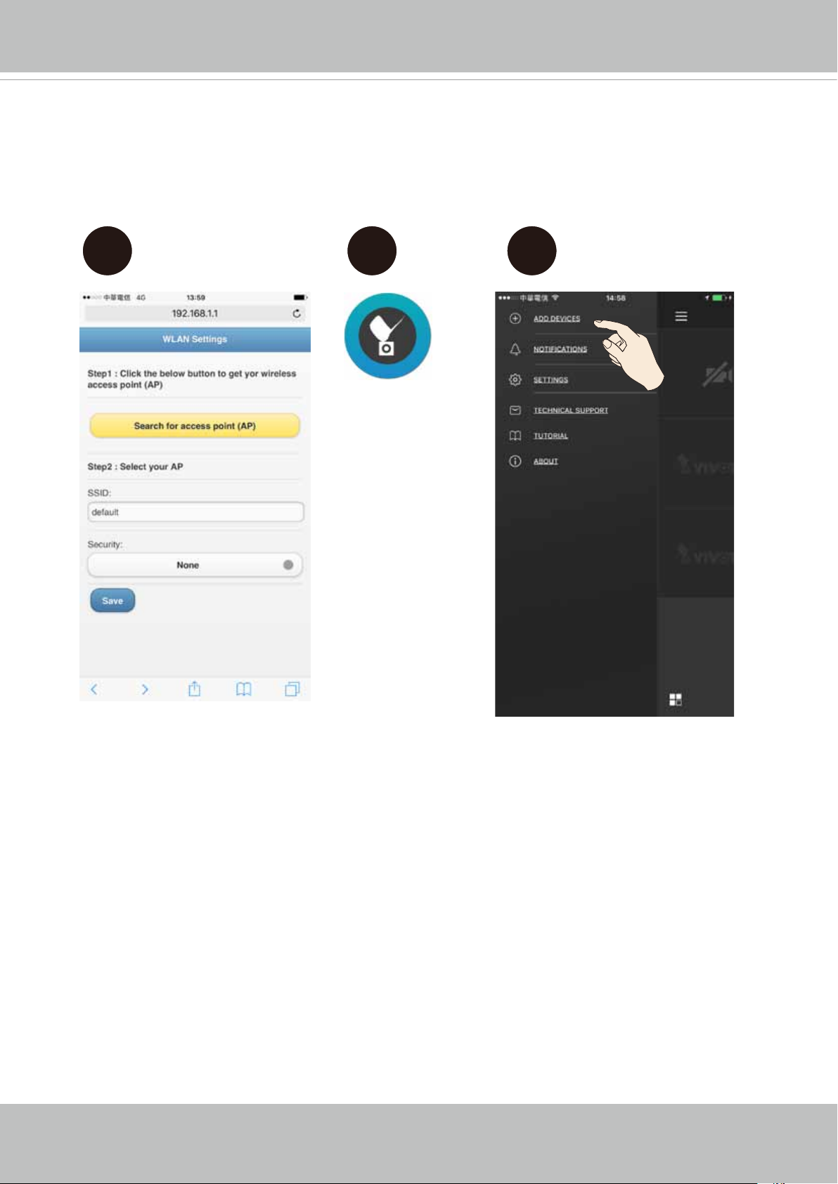
C-5. Enter the credentials for log in to your AP.
C-6. When the camera is connected to an AP, it enters the client mode. You should then
install and open the iViewer utility from your app store.
C-7. Add the camera to your iView utility.
C-5
C-6 C-7
iViewer
14 - User's Manual
VIVOTEK
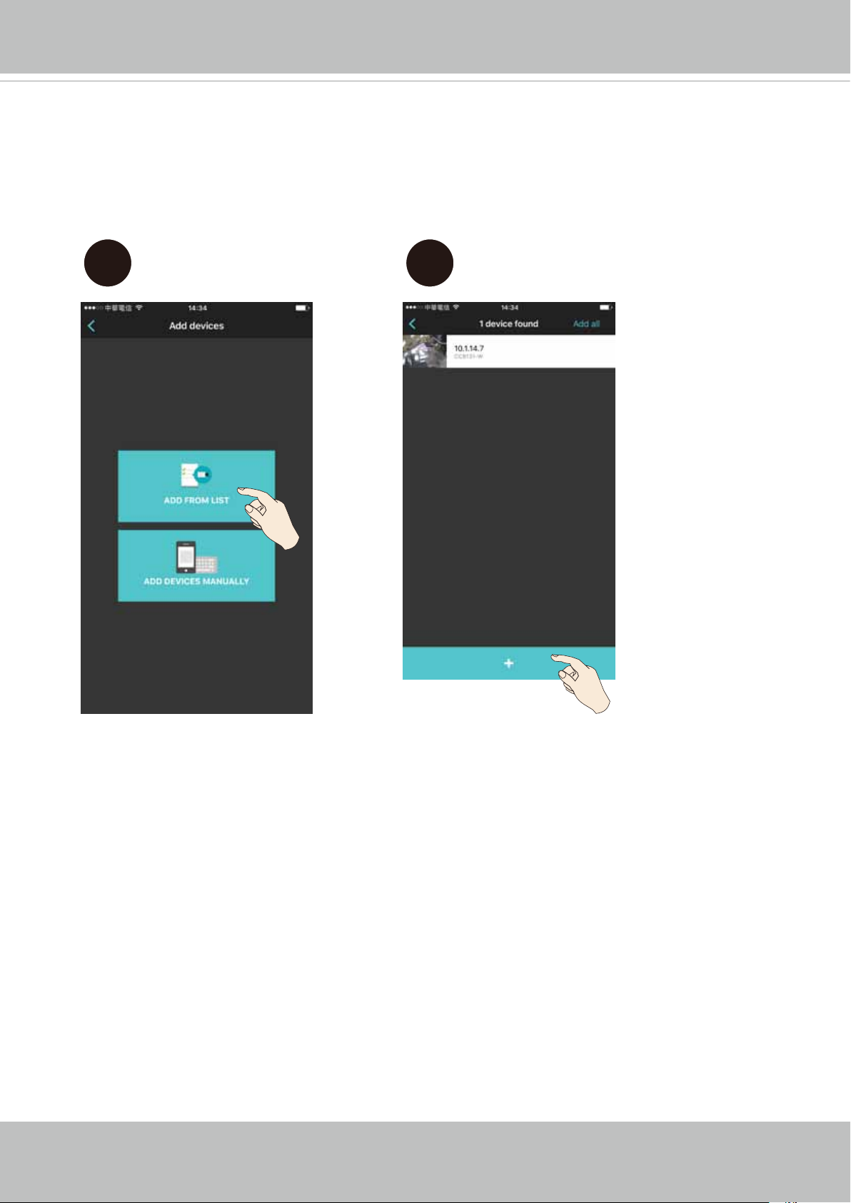
C-8. You can click on Add from List. The iViewer will search within your current network for
the camera.
C-9. Once found, you can add the camera into your conguration. Please refer to the
documentation that came with iViewer for information.
C-8 C-9
User's Manual - 15
VIVOTEK
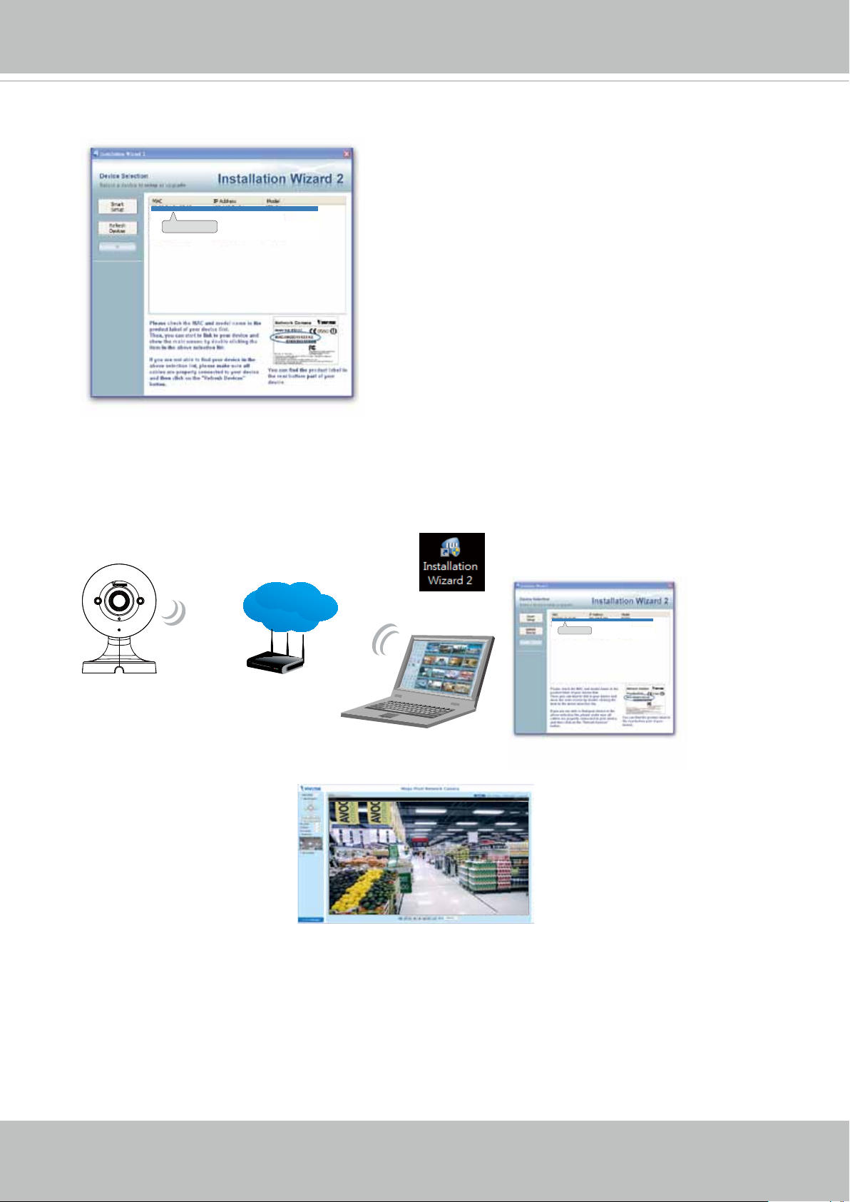
6. Open the IW2 utility. The utility will search for cameras within the network.
00-02-D1-73-02-02 192.168.5.151 IP8160-W
0002D1730202
7. Double-click on the camera to open a web console with the camera. You can now start
viewing the live stream.
LAN
Browser
IW2
00-02-D1-73-02-02 192.168.5.151 IP8160-W
0002D1730202
16 - User's Manual
VIVOTEK
SD/SDHC/SDXC Card Capacity
This network camera is compliant with SD/SDHC/SDXC 16GB / 8GB / 32GB / 64GB and
other preceding standard SD cards.
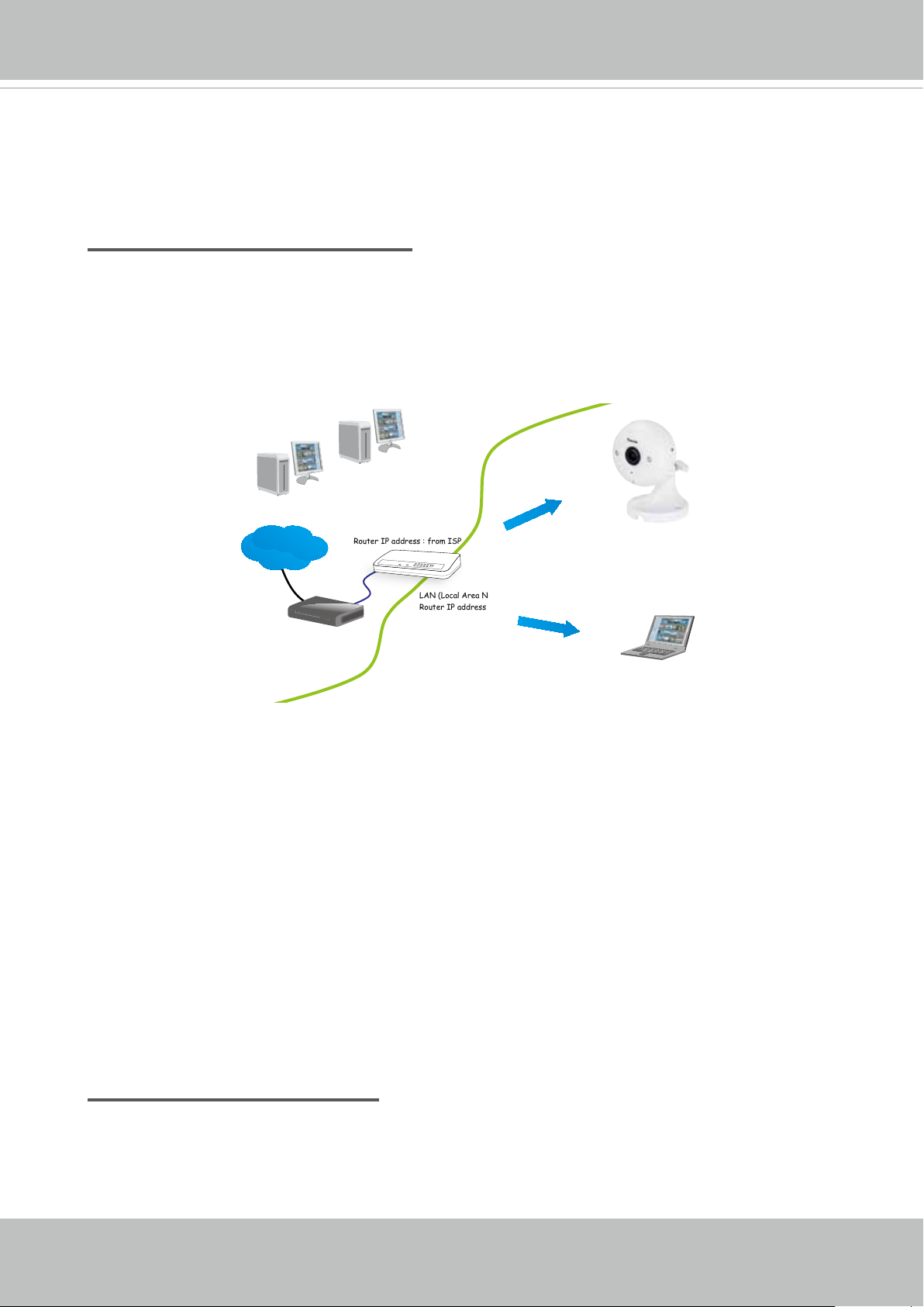
Internet connection via a router
Before setting up the Network Camera over the Internet, make sure you have a router and
follow the steps below.
1. Connect your Network Camera behind a router, the Internet environment is illustrated
below. Regarding how to obtain your IP address, please refer to Software Installation on
page 19 for details.
Internet
Cable or DSL Modem
WAN (Wide Area Network )
Router IP address : from ISP
LINK
POWER
COLLISION
RECEIVE
1
2
PARTITION
3
4
5
LAN (Local Area Network)
Router IP address : 192.168.0.1
IP address : 192.168.0.3
Subnet mask : 255.255.255.0
Default router : 192.168.0.1
IP address : 192.168.0.2
Subnet mask : 255.255.255.0
Default router : 192.168.0.1
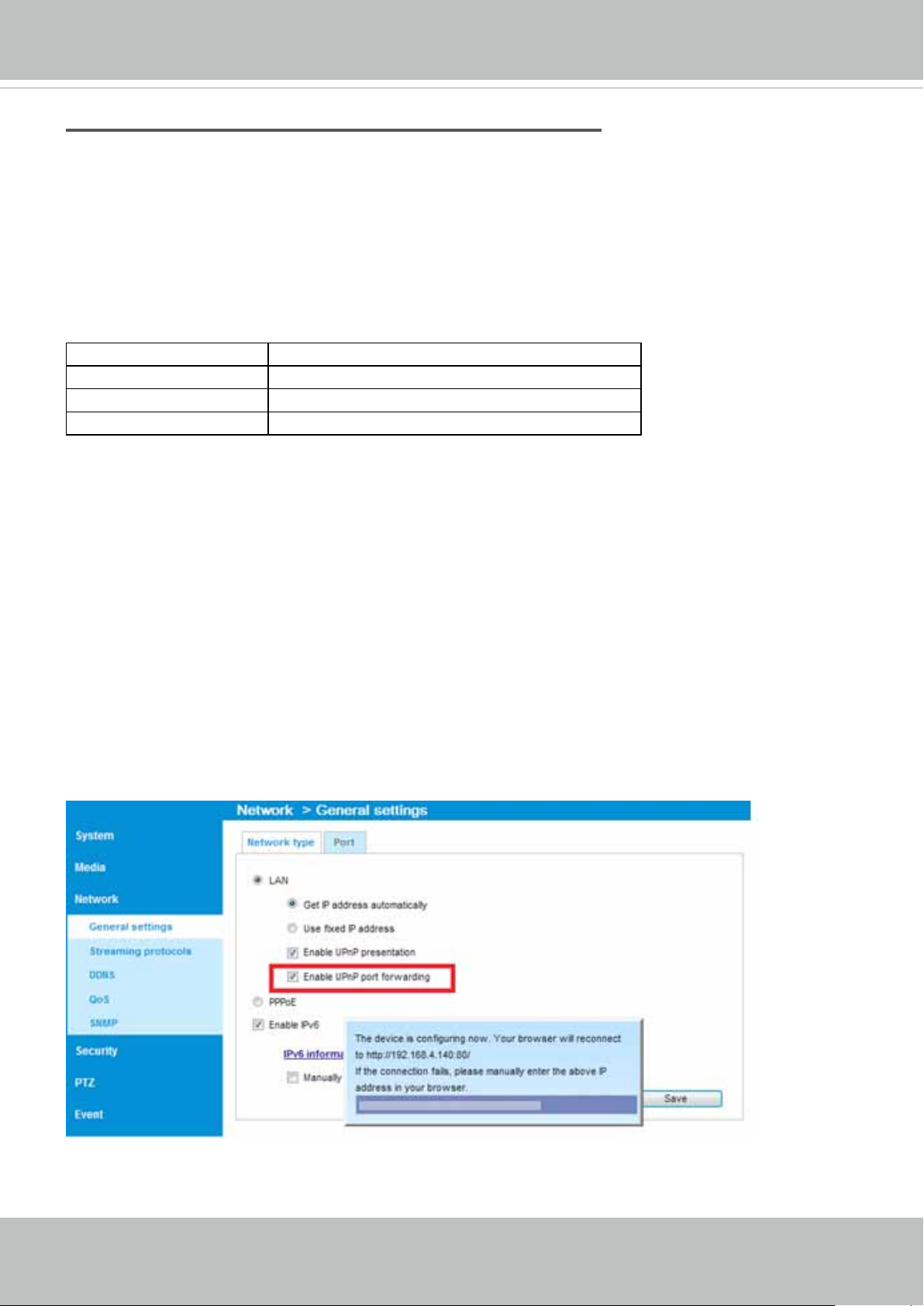
2. In this case, if the Local Area Network (LAN) IP address of your Network Camera is
192.168.0.3, please forward the following ports for the Network Camera on the router.
■ HTTP port: default is 80
■ RTSP port: default is 554
■ RTP port for video: default is 5556
■ RTCP port for video: default is 5557
If you have changed the port numbers on the Network page, please open the ports
accordingly on your router. For information on how to forward ports on the router, please
refer to your router’s user’s manual.
3. Find out the public IP address of your router provided by your ISP (Internet Service
Provider).
Use the public IP and the secondary HTTP port to access the Network Camera from the
Internet. Please refer to Network Type on page 70 for details.
Internet connection with static IP
Choose this connection type if you are required to use a static IP for the Network Camera.
Please refer to LAN setting on page 69 for details.
User's Manual - 17
VIVOTEK
Internet connection via PPPoE (Point-to-Point over Ethernet)
Choose this connection type if you are connected to the Internet via a DSL Line. Please refer to
PPPoE on page 70 for details.
Congure the router, virtual server or rewall, so that the router can forward any data coming
into a pre-congured port number to a network camera on the private network, and allow data
from the camera to be transmitted to the outside of the network over the same path.
From Forward to
122.146.57.120:8000 192.168.2.10:80
122.146.57.120:8001 192.168.2.11:80
... ...
When properly congured, you can access a camera behind the router using the HTTP request
such as follows: http://122.146.57.120:8000
If you change the port numbers on the Network conguration page, please open the ports accordingly on your router. For example, you can open a management session with your router to
congure access through the router to the camera within your local network. Please consult your
network administrator for router conguration if you have troubles with the conguration.
For more information with network conguration options (such as that of streaming ports),
please refer to Conguration > Network Settings. VIVOTEK also provides the automatic port for-
warding feature as an NAT traversal function with the precondition that your router must support
the UPnP port forwarding feature.
18 - User's Manual
VIVOTEK
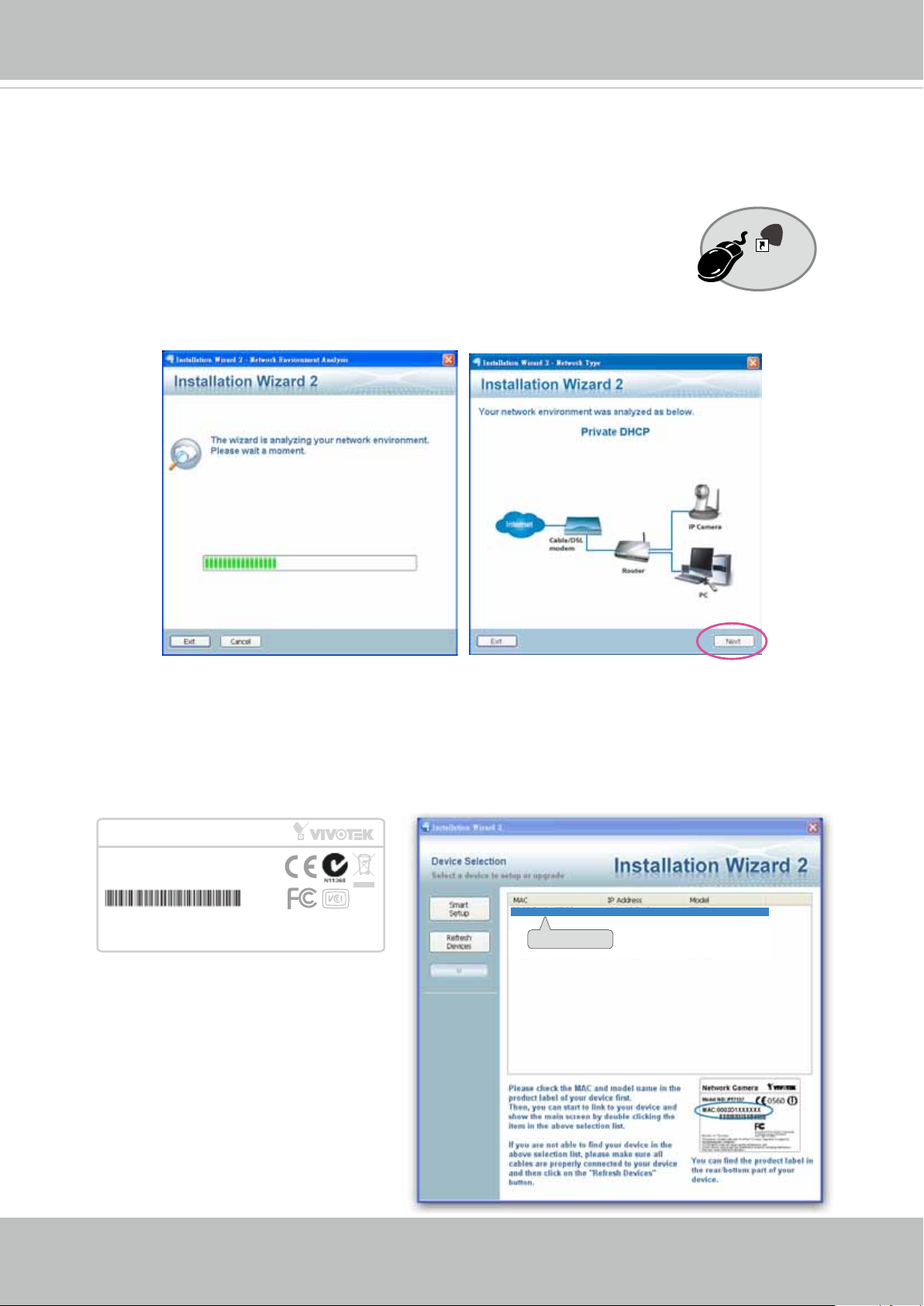
Software Installation
Installation Wizard 2 (IW2), a software included in the product CD, helps you set up your
Network Camera on the LAN.
IW
1. Install IW2 under the Software Utility directory from the software CD.
Double-click the IW2 shortcut on your desktop to launch the program.
2. The program will conduct an analysis of your network environment.
After your network environment is analyzed, please click Next to continue the program.
2
Installation
Wizard 2
3. The program will search for all VIVOTEK network devices on the same LAN.
4. After a brief search, the installer window will prompt. Click on the MAC and model name
that matches the one printed on the product label. You can then double-click on the address
to open a management session with the Network Camera.
Network Camera
Model No: IP8160-W
MAC:0002D1730202
This device complies with part 15 of the FCC rules. Operation is subject to the following two conditions:
(1)This device may not cause harmful interference, and
(2) this device must accept any interference received, including interference that may cause undesired operation.
Pat. 6,930,709
R o HS
Made in Taiwan
00-02-D1-73-02-02 192.168.5.151 IP8160-W
0002D1730202
User's Manual - 19
VIVOTEK
Ready to Use
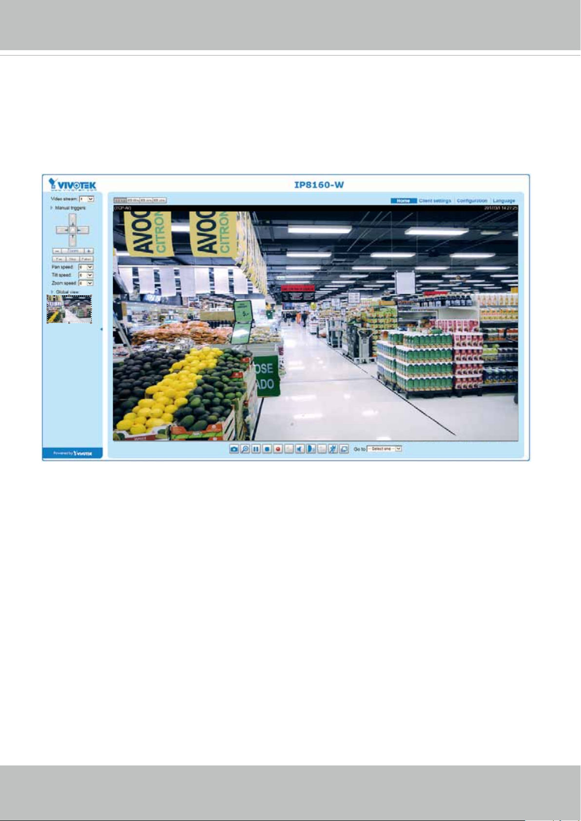
1. A browser session with the Network Camera should prompt as shown below.
2. You should be able to see live video from your camera. You may also install the 32-channel
recording software from the software CD in a deployment consisting of multiple cameras. For
its installation details, please refer to its related documents.
20 - User's Manual
VIVOTEK
Accessing the Network Camera
This chapter explains how to access the Network Camera through web browsers, RTSP players,
3GPP-compatible mobile devices, and VIVOTEK recording software.
Using Web Browsers
Use Installation Wizard 2 (IW2) to access the Network Cameras on LAN.
If your network environment is not a LAN, follow these steps to access the Netwotk Camera:
1. Launch your web browser (e.g., Microsoft
2. Enter the IP address of the Network Camera in the address eld. Press Enter.
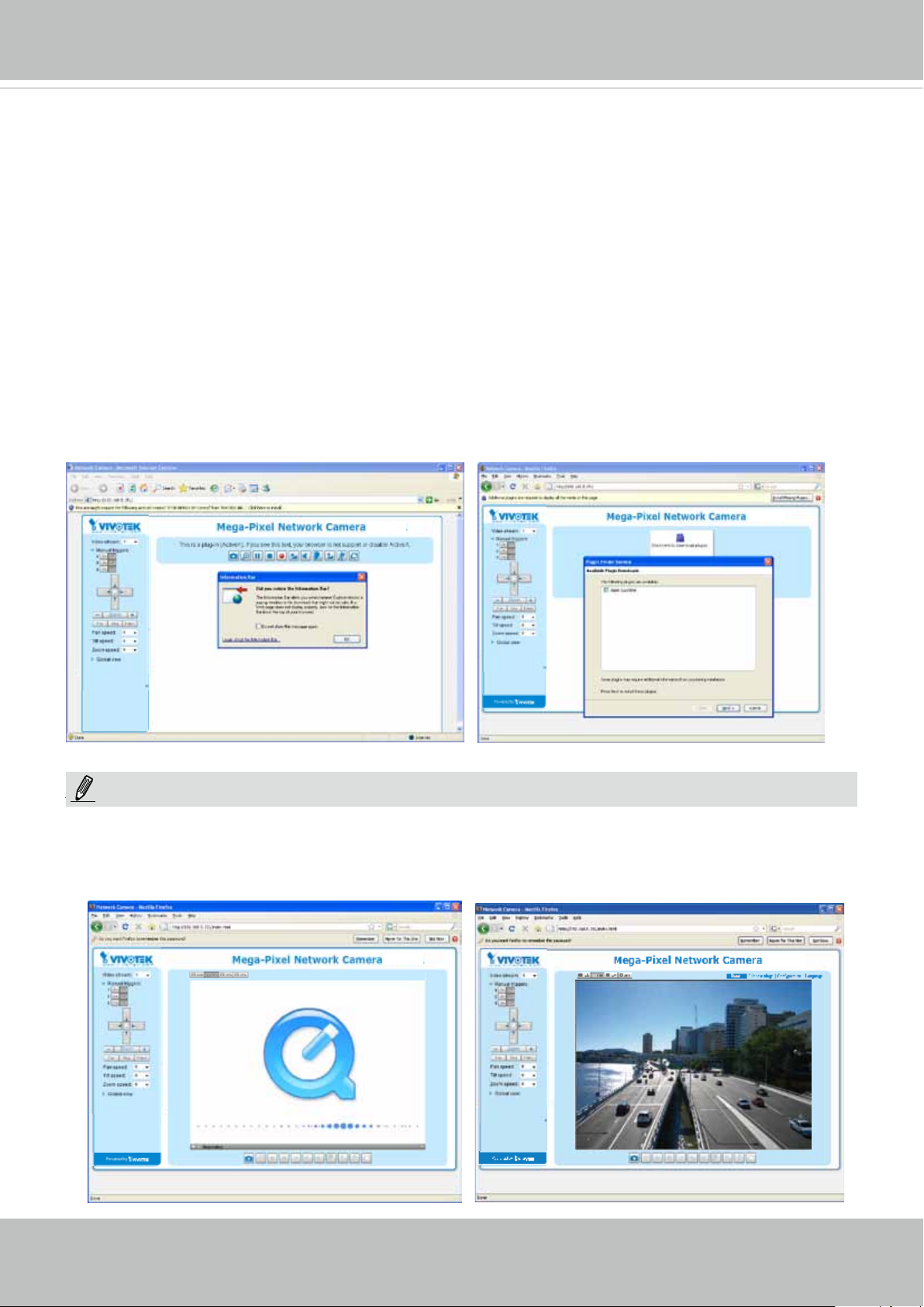
3. Live video will be displayed in your web browser.
4. If it is the rst time installing the VIVOTEK network camera, an information bar will prompt as
shown below. Follow the instructions to install the required plug-in on your computer.
®
Internet Explorer or Mozilla Firefox).
NOTE:
NOTE
► For Mozilla Firefox or Chrome users, your browser will use QuickTime to stream the live
video. If you don’t have QuickTime on your computer, please download it rst, then launch
the web browser.
User's Manual - 21
VIVOTEK
► By default, the Network Camera is not password-protected. To prevent unauthorized access,
it is highly recommended to set a password for the Network Camera.
For more information about how to enable password protection, please refer to Security on
page 89.
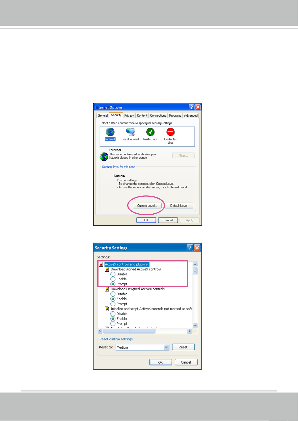
► If you see a dialog box indicating that your security settings prohibit running ActiveX
®
Controls, please enable the ActiveX
Controls for your browser.
®
1. Choose Tools > Internet Options > Security > Custom Level.
2. Look for Download signed ActiveX
®
controls; select Enable or Prompt. Click OK.
3. Refresh your web browser, then install the ActiveX
complete installation.
®
control. Follow the instructions to
22 - User's Manual
VIVOTEK
IMPORTANT:
Currently the Network Camera utilizes a 32-bit ActiveX plugin. You CAN NOT open a
•
management/view session with the camera using a 64-bit IE browser.
If you encounter this problem, try execute the Iexplore.exe program from C:\Windows\
•
SysWOW64. A 32-bit version of IE browser will be installed.
On Windows 7, the 32-bit explorer browser can be accessed from here:
•
C:\Program Files (x86)\Internet Explorer\iexplore.exe
If you open a web session from the IW2 utility, a 32-bit IE browser will be opened.
•
Tips:
1. The onscreen Java control can malfunction under the following situations: A PC connects to different cameras that are using the same IP address (or the same camera
running different rmware versions). Removing your browser cookies will solve this
problem.
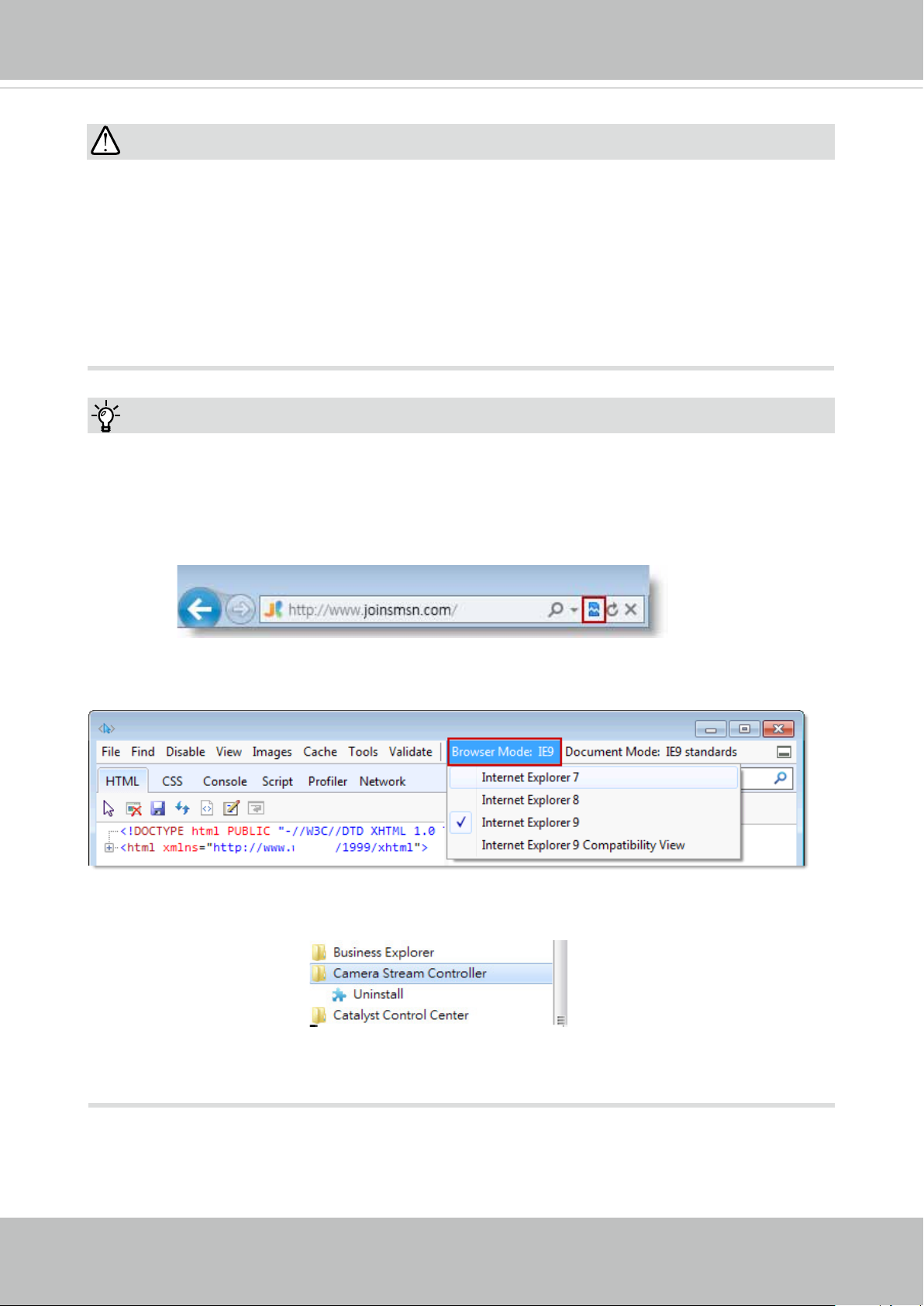
2. If you encounter problems with displaying the conguration menus or UI items, try disable the Compatibility View on IE8 or IE9.
You may also press the F12 key to open the developer tools utility, and then change the
Browser Mode to the genuine IE8 or IE9 mode.
• In the event of plug-in compatibility issues, you may try to uninstall the plug-in that was
previously installed.
User's Manual - 23
VIVOTEK
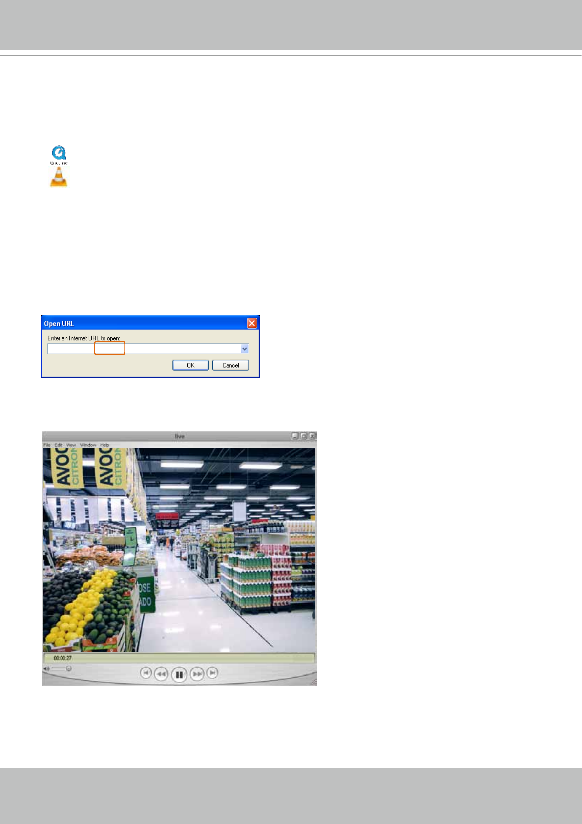
Using RTSP Players
To view the streaming media using RTSP players, you can use one of the following players that
support RTSP streaming.
Quick Time Player
VLC media player
VLC media player
1. Launch the RTSP player.
mpegable Player
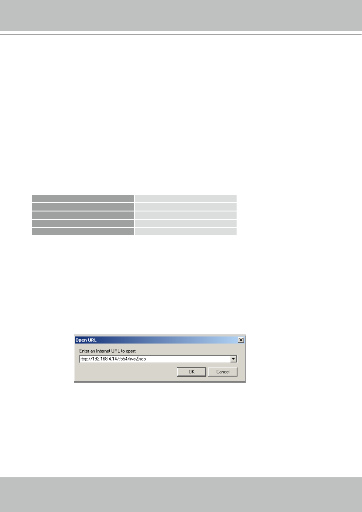
2. Choose File > Open URL. A URL dialog box will pop up.
3. The address format is rtsp://<ip address>:<rtsp port>/<RTSP streaming access name for
pvPlayer
stream1 or stream2>
As most ISPs and players only allow RTSP streaming through port number 554, please set the
RTSP port to 554. For more information, please refer to RTSP Streaming on page 77.
For example:
rtsp://192.168.5.151:554/live.sdp
4. The live video will be displayed in your player.
For more information on how to configure the RTSP access name, please refer to RTSP
Streaming on page 77 for details.
24 - User's Manual
VIVOTEK
Video quality (Constant bit rate) 40kbps
Using 3GPP-compatible Mobile Devices
To view the streaming media through 3GPP-compatible mobile devices, make sure the Network
Camera can be accessed over the Internet. For more information on how to set up the Network
Camera over the Internet, please refer to Setup the Network Camera over the Internet on page
17.
To utilize this feature, please check the following settings on your Network Camera:
1. Because most players on 3GPP mobile phones do not support RTSP authentication, make
sure the authentication mode of RTSP streaming is set to disable.
For more information, please refer to RTSP Streaming on page 77.
2. As the the bandwidth on 3G networks is limited, you will not be able to use a large video size.
Please set the video streaming parameters as listed below.
For more information, please refer to Stream settings on page 59.
Video Mode H.264
Frame size 176 x 144
Maximum frame rate 5 fps
Intra frame period 1S
3. As most ISPs and players only allow RTSP streaming through port number 554, please set
the RTSP port to 554. For more information, please refer to RTSP Streaming on page 77.
4. Launch the player on the 3GPP-compatible mobile devices (e.g., QuickTime).
5. Type the following URL commands into the player.
The address format is rtsp://<public ip address of your camera>:<rtsp port>/<RTSP streaming
access name for stream # with small frame size and frame rate>.
For example:
You can configure Stream #2 into the suggested stream settings as listed above for live
viewing on a mobile device.
User's Manual - 25
VIVOTEK
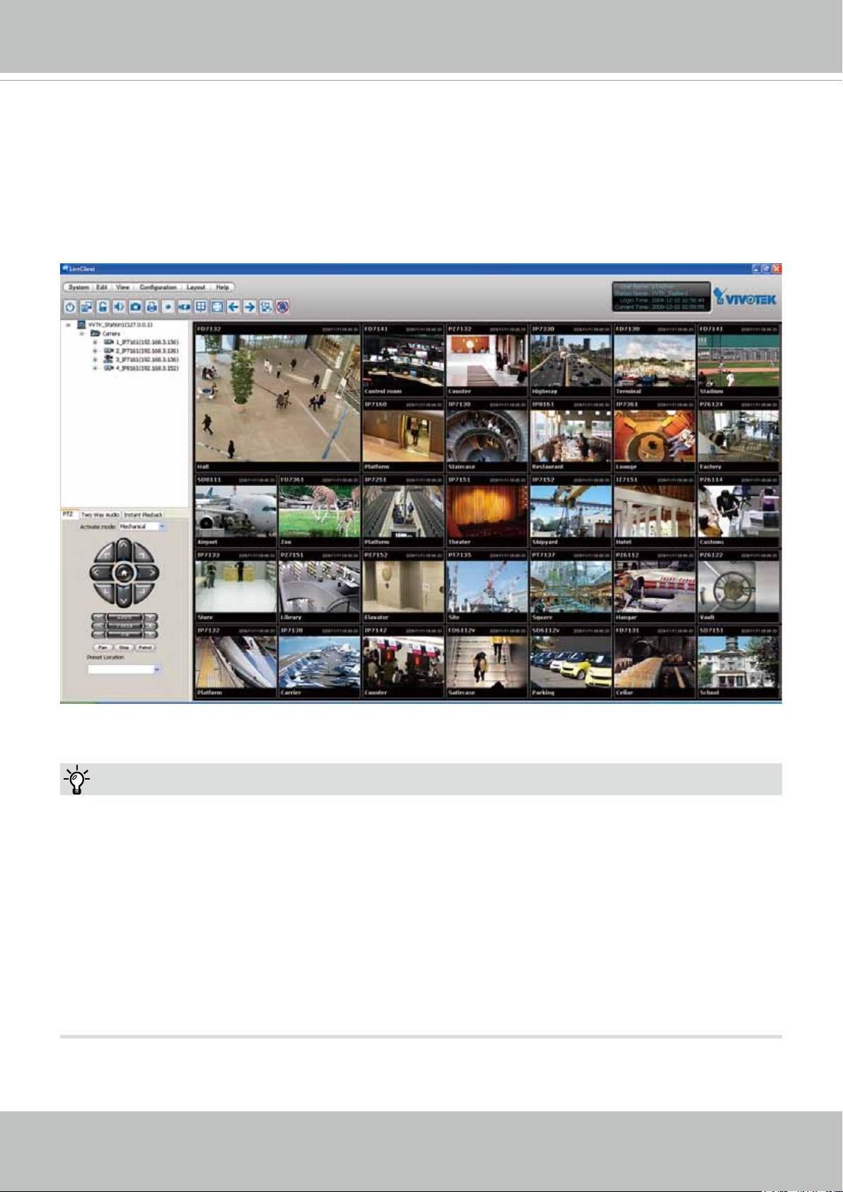
Using VIVOTEK Recording Software
The product software CD also contains a VAST recording software, allowing simultaneous
monitoring and video recording for multiple Network Cameras. Please install the recording
software; then launch the program to add the Network Camera to the Channel list. For detailed
information about how to use the recording software, please refer to the user’s manual of the
software or download it from http://www.vivotek.com.
Tips:
1. If you forget the root (administrator) password for the camera, you can restore the camera
defaults by pressing the reset button for longer than 7 seconds.
2. If DHCP is enabled in your network, and the camera cannot be accessed, run the IW2 utility
to search the network. If the camera has been congured with a xed IP that does not comply
with your local network, you may see its default IP 169.254.x.x. If you still cannot find the
camera, you can restore the camera to its factory defaults. The factory default is DHCP client.
3. If you change your network parameters, e.g., added a camera via a connection to a LAN
card, re-start the IW2 utility.
26 - User's Manual

VIVOTEK
Main Page
This chapter explains the layout of the main page. It is composed of the following sections:
VIVOTEK INC. Logo, Host Name, Camera Control Area, Configuration Area, Menu, and Live
Video Window.
Resize Buttons
VIVOTEK INC.
Logo
Camera Control
Area
Host Name
Configuration
Area
Hide Button
Live View Window
VIVOTEK INC. Logo
Click this logo to visit the VIVOTEK website.
Host Name
The host name can be customized to t your needs. The name can be changed especially there are many
cameras in your surveillance deployment. For more information, please refer to System on page 38.
Camera Control Area
Video Stream: This Network Camera supports multiple streams (streams 1 and 2) simultaneously. You
can select any of them for live viewing. For more information about multiple streams, please refer to page
59 for detailed information.
Manual Trigger: Click to enable/disable an event trigger manually. Please congure an event setting on
the Application page before you enable this function. A total of 3 event conguration can be congured.
For more information about event setting, please refer to page 103. If you want to hide this item on
the homepage, please go to Configuration> System > Homepage Layout > General settings >
Customized button to deselect the “show manual trigger button” checkbox.
User's Manual - 27
VIVOTEK
H.264 Protocol and Media Options
Conguration Area
Client Settings: Click this button to access the client setting page. For more information, please refer to
Client Settings on page 32.
Conguration: Click this button to access the conguration page of the Network Camera. It is suggested
that a password be applied to the Network Camera so that only the administrator can configure the
Network Camera. For more information, please refer to Conguration on page 37.
Language: Click this button to choose a language for the user interface. Language options are available
in: English, Deutsch, Español, Français, Italiano,
日本語,
Português,
簡体中文
繁體中文,
,
and
Ρусский
Please note that you can also change a language on the Conguration page; please refer to page 37.
Hide Button
You can click the hide button to hide or display the control panel.
Resize Buttons
:
Click the Auto button, the video cell will resize automatically to t the monitor.
Click 100% is to display the original homepage size.
Click 50% is to resize the homepage to 50% of its original size.
Click 25% is to resize the homepage to 25% of its original size.
.
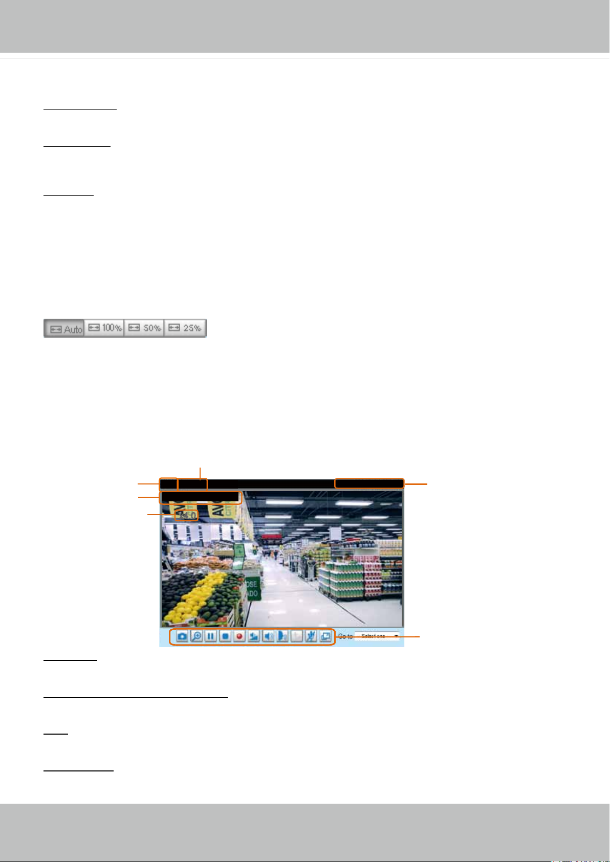
Live Video Window
■ The following window is displayed when the video mode is set to H.264:
Video Title
Title and Time
Zoom Indicator
Video (TPC-AV)
Video 17:08:56 2017/03/25
x4.0
Video Title: The video title can be congured. For more information, please refer to Video Settings on
page 50.
H.264 Protocol and Media Options: The transmission protocol and media options for H.264 video
streaming. For further conguration, please refer to Client Settings on page 32.
2017/03/25 17:08:56
Time
Video Control Buttons
Time: Display the current time. For further conguration, please refer to Media > Image > Genral settings
on page 50.
Title and Time: The video title and time can be stamped on the streaming video. For further conguration,
please refer to Media > Image > General settings on page 53.
28 - User's Manual
VIVOTEK
PTZ Panel: This Network Camera supports “digital“ (e-PTZ) pan/tilt/zoom control, which allows roaming
a smaller view frame within a large view frame. Please refer to PTZ settiings on page 100 for detailed
information.
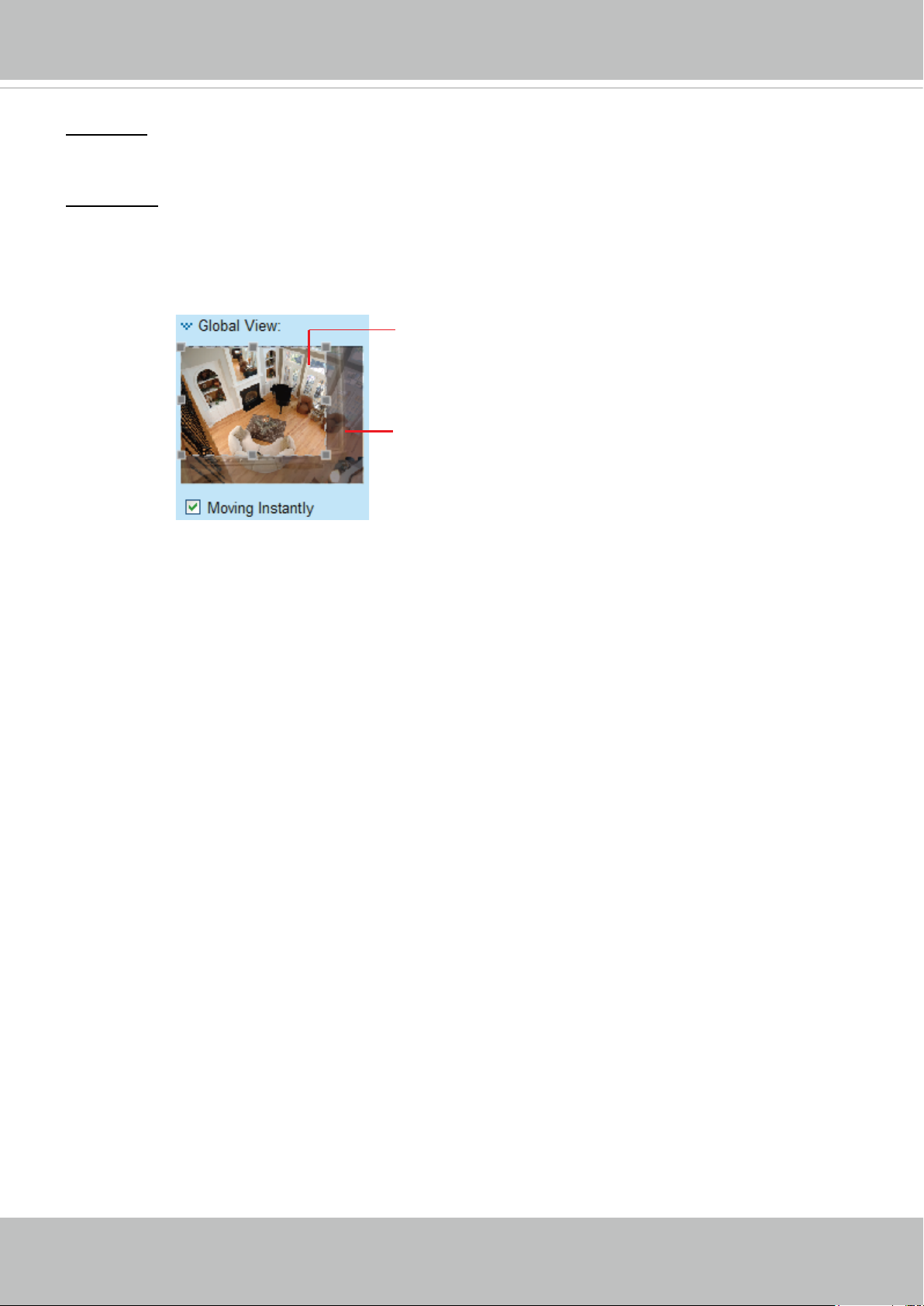
Global View: Click on this item to display the Global View window. The Global View window contains a
full view image (the largest frame size of the captured video) and a oating frame (the viewing region of
the current video stream). The oating frame allows users to control the e-PTZ function (Electronic Pan/
Tilt/Zoom). For more information about e-PTZ operation, please refer to E-PTZ Operation on page 100.
For more information about how to set up the viewing region of the current video stream, please refer to
page 100.
The viewing region of
the curruent video
stream
The largest frame size
Note that the PTZ buttons on the panel are not operational unless you are showing only a portion of the
full image. If the live view window is displaying the full view, the PTZ buttons are not functional.
User's Manual - 29
VIVOTEK
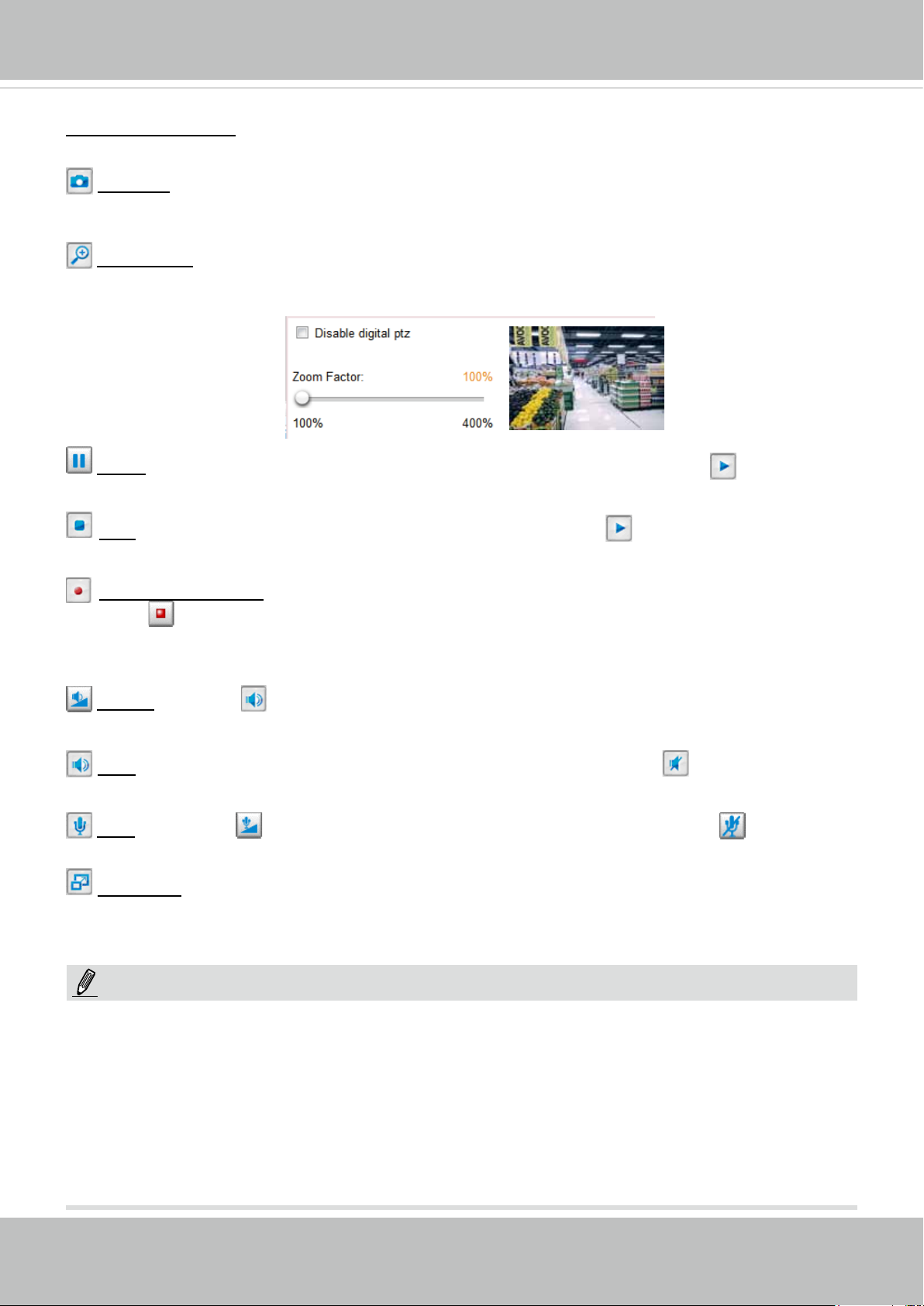
Video Control Buttons: Depending on the Network Camera model and Network Camera conguration,
some buttons may not be available.
Snapshot: Click this button to capture and save still images. The captured images will be displayed
in a pop-up window. Right-click the image and choose Save Picture As to save it in JPEG (*.jpg) or BMP
(*.bmp) format.
Digital Zoom: Click and uncheck “Disable digital zoom” to enable the zoom operation. The navigation
screen indicates the part of the image being magnied. To control the zoom level, drag the slider bar. To
move to a different area you want to magnify, drag the navigation screen.
Pause: Pause the transmission of the streaming media. The button becomes the Resume button
after clicking the Pause button.
Stop: Stop the transmission of the streaming media. Click the Resume button to continue
transmission.
Start MP4 Recording: Click this button to record video clips in MP4 file format to your computer.
Press the
recording stops accordingly. To specify the storage destination and le name, please refer to MP4 Saving
Options on page 33 for details.
Volume: When the Mute function is not activated, move the slider bar to adjust the volume on the
local computer.
Mute: Turn off the volume on the local computer. The button becomes the Audio On button after
clicking the Mute button.
Mute: Turn off the Mic volume on the local computer. The button becomes the Mic On button
after clicking the Mute button.
Full Screen: Click this button to switch to full screen mode. Press the “Esc” key to switch back to normal
mode.
Stop MP4 Recording button to end recording. When you exit the web browser, video
NOTE:
1. For a megapixel camera, it is recommended to use monitors of the 24" size or larger, and
are capable of 1600x1200 or better resolutions.
2. Below are the defaults for Audio settings:
For cameras with built-in microphone: Not Muted.
For cameras without built-in microphone: Muted.
To receive audio input from an external microphone, you may need to enable the audio input
from Media > Audio. Refer to page 68 for more information.
30 - User's Manual
Loading...