


Product name: |
Speed Dome Camera (SD61x2V) |
|
Release Date: |
2006/04/17 |
|
Manual Revision: |
1.01 |
|
Web site: |
www.vivotek.com |
|
Email: |
technical@vivotek.com |
|
|
sales@vivotek.com |
|
Made in Taiwan. |
©Copyright 2000-2006. |
All rights reserved |
- 1 -
www.vivotek.com
T: 886-2-82455282
F: 886-2-82455532

Before You Use This Product
The use of surveillance devices may be prohibited in your country by law. The Network Camera is not only a high-performance web-ready camera but also can be part of a flexible surveillance system. It is the user’s responsibility to ensure that the operation of such devices is legal before installing this unit for its intended use.
It is important to first verify that all contents received are complete according to the list in the "Package Contents" chapter. Take notice of the warnings in “Quick installation guide” before the Network Camera is installed, then carefully read and follow the instructions in the “Installation” chapter to avoid damages due to faulty assembly and installation. This also ensures the product is used properly as intended.
The Network Camera is a network device and its use should be straightforward for those who have basic network knowledge. The “Troubleshooting” chapter in the Appendix provides remedies to the most common errors in set up and configuration. You should consult this chapter first if you run into a system error.
The Network Camera is designed for various applications including video sharing, general security/surveillance, etc. The “How to Use” chapter suggests ways to best utilize the Network Camera and ensure proper operations. For the creative and professional developers, the "URL Commands of the Network Camera" chapter serves to be a helpful reference to customize existing homepages or integrating with the current web server.
For paragraphs preceded by  the reader should use caution to understand
completely the warnings. Ignoring the warnings may result in serious hazards or injuries.
- 2 -
www.vivotek.com
T: 886-2-82455282
F: 886-2-82455532
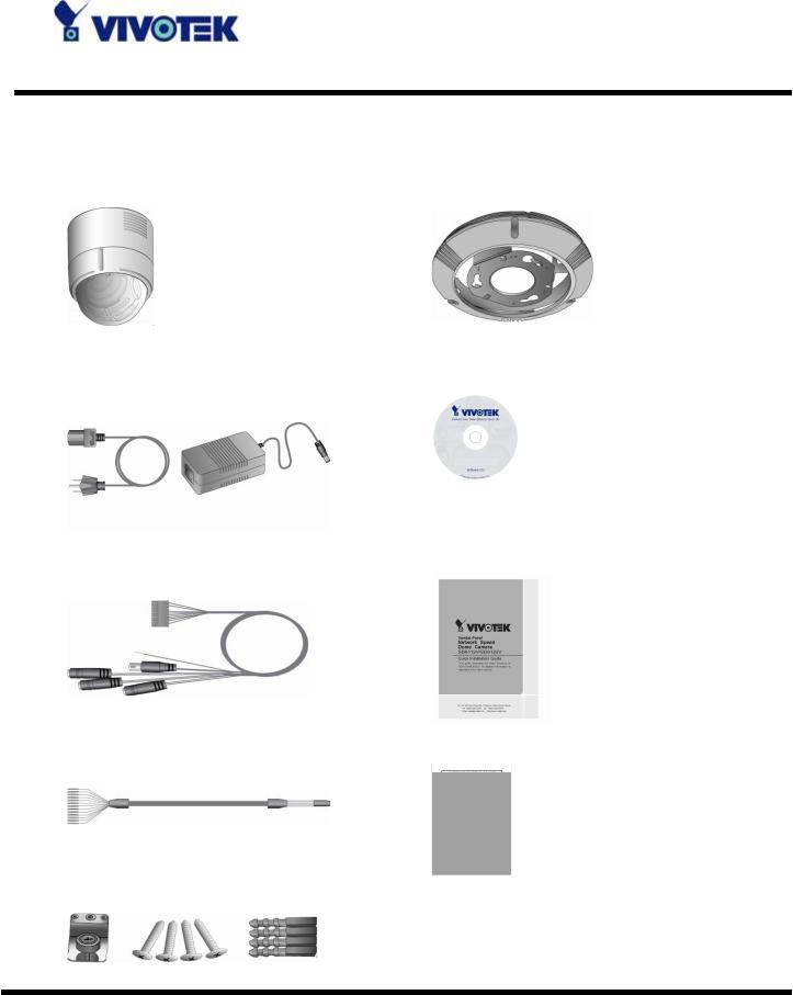
Package Contents
SD61x2V |
Hard Ceiling Mount |
DC Power adapter |
Software CD |
Data Cable |
Quick installation guide |
Alarm Cable |
Warranty card |
Fixing Plate
- 3 -
www.vivotek.com
T: 886-2-82455282
F: 886-2-82455532

Table of Contents
Before You Use This Product.................................................................... |
2 |
Package Contents .................................................................................... |
3 |
Table of Contents ............................................................................................ |
1 |
Installation .............................................................................................. |
4 |
Hardware Installation ........................................................................... |
4 |
Alarm Cable Wiring ................................................................... |
4 |
Indoor Dome Installation ...................................................................... |
5 |
Hard Ceiling Mounting................................................................ |
5 |
In-Ceiling Mounting ................................................................... |
8 |
To install in Ethernet................................................................ |
11 |
Software Installation .......................................................................... |
12 |
Initial Access to the Network Camera.................................................... |
16 |
Installing Plug-in .......................................................................... |
16 |
Check Network Settings ................................................................ |
17 |
Add Password to Prevent Unauthorized Access.................................. |
18 |
How to Use ............................................................................................ |
19 |
Authentication ................................................................................... |
19 |
Primary User’s Capabilities .................................................................. |
20 |
Main Screen with Camera View....................................................... |
20 |
The Configuration: .................................................................. |
21 |
The camera view..................................................................... |
22 |
The pan/tilt/zoom control buttons: ............................................ |
22 |
The CCD control buttons: ......................................................... |
23 |
Client Settings ............................................................................. |
24 |
Administrator’s Capabilities ................................................................. |
26 |
Fine-tuning for Best Performance.................................................... |
26 |
For Best Real-time Video Images............................................... |
27 |
Only Quality Images Will Do ..................................................... |
27 |
Somewhere Between Real-time and Clear Images ....................... |
28 |
- 1 - |
|
www.vivotek.com
T: 886-2-82455282
F: 886-2-82455532

Select for Motion JPEG ............................................................. |
28 |
Opening Accounts for New Users .................................................... |
29 |
Protect Network Camera by Passwords....................................... |
29 |
More Flexible Options for Viewers .............................................. |
30 |
Build a Multimedia Web Attraction Site............................................. |
30 |
Demo on Multiple Sites – Mid-scale Service................................. |
30 |
Product Demo for E-business – Large-scale Service ..................... |
30 |
If the web space has FTP service............................................... |
31 |
If the web space has no FTP service .......................................... |
32 |
Build a Security Application............................................................ |
34 |
Send Snapshots When Motion is Detected .................................. |
35 |
Definitions in Configuration ................................................................... |
37 |
System Parameters ............................................................................ |
38 |
User Group Administration .................................................................. |
39 |
Edit User ..................................................................................... |
41 |
General....................................................................................... |
42 |
HTTP .......................................................................................... |
42 |
Streaming ................................................................................... |
43 |
DDNS & UPnP.................................................................................... |
44 |
Mail & FTP......................................................................................... |
46 |
SMTP .......................................................................................... |
46 |
FTP ............................................................................................ |
46 |
Video Codec Parameters ..................................................................... |
49 |
Image Settings ............................................................................ |
51 |
Camera Settings........................................................................... |
52 |
Audio ............................................................................................... |
53 |
Motion Detection................................................................................ |
55 |
Camera Control ................................................................................. |
56 |
Camera control area ................................................................ |
56 |
Preset function area ................................................................ |
56 |
Application Setup ............................................................................... |
59 |
Weekly Schedule .......................................................................... |
59 |
Event Operation ........................................................................... |
59 |
- 2 -
www.vivotek.com
T: 886-2-82455282
F: 886-2-82455532

Sequential Operation .................................................................... |
60 |
Viewing System Log ........................................................................... |
62 |
Viewing System Parameters ................................................................ |
62 |
Factory Default .................................................................................. |
62 |
Appendix ............................................................................................... |
63 |
A. Troubleshooting ............................................................................. |
63 |
B. Frequently Asked Questions............................................................. |
64 |
B. Cleaning the Lens........................................................................... |
67 |
C. Pan/Tilt/Zoom Data ........................................................................ |
67 |
D. URL Commands of the Network Camera ............................................ |
69 |
Overview..................................................................................... |
69 |
Style Convention .......................................................................... |
69 |
General CGI URL Syntax and Parameters ......................................... |
70 |
Get Server Parameter Values.......................................................... |
70 |
Set Server Parameter Values.......................................................... |
72 |
Available Parameters on the Server ................................................. |
73 |
Drive the Digital Output................................................................. |
82 |
Query Status of the Digital Input .................................................... |
83 |
Capture Single Snapshot ............................................................... |
84 |
Account Management.................................................................... |
85 |
System Logs ................................................................................ |
86 |
Configuration File ......................................................................... |
87 |
Upload File (firmware)................................................................... |
87 |
Camera Control ............................................................................ |
88 |
Recall ......................................................................................... |
89 |
Position....................................................................................... |
90 |
System Information ...................................................................... |
92 |
Preset Locations ........................................................................... |
93 |
E. Technical Specifications ................................................................... |
94 |
- 3 -
www.vivotek.com
T: 886-2-82455282
F: 886-2-82455532
Installation
Hardware Installation
Please verify that your product package contains all the accessories listed in the foregoing Package Contents. Depending on the user’s application, an Ethernet cable may be needed. The Ethernet cable should meet the specs of UTP Category 5 and not exceed 100 meters in length.
 Connect the power adapter jack to the Network Camera before plugging in to the power socket. This will reduce the risk of accidental electric shock.
Upon powering up, the device runs through a self-test procedure and the front LEDs will blink between green and red for a few times. If self-test passes, the LEDs will shut off and the Network Camera will be on stand-by and ready for software installation. If self-test fails the red LED will blink several times. Refer to Appendix A for troubleshooting.
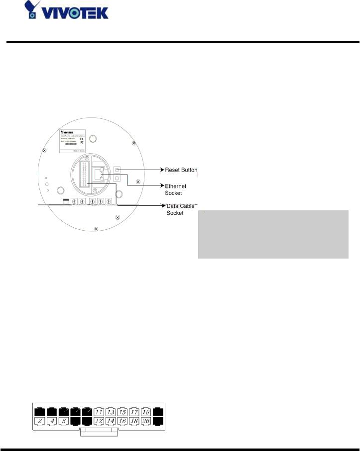
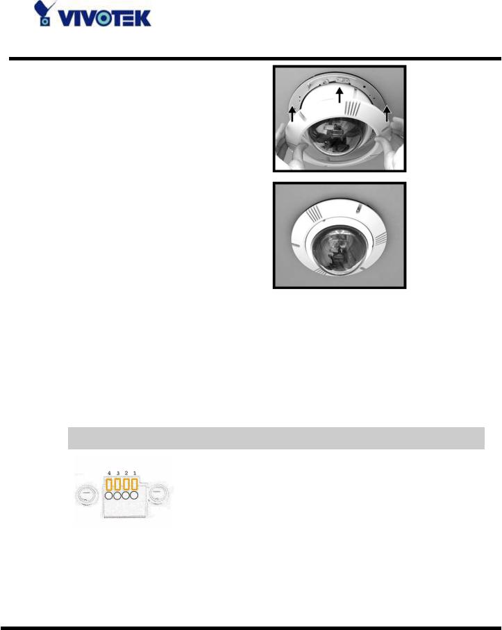
Alarm Cable Wiring
The alarm pins are serviceable for connecting alarm input and output devices, such as alarm sensors, sirens or flashing lights with the surveillance system. The table shown as follows lists the definition of alarm pins on the 22-pin connector located on the bottom of the dome camera.
- 4 -
www.vivotek.com
T: 886-2-82455282
F: 886-2-82455532

Pin |
Cable Color |
Definition |
2 |
White |
ALM NO |
|
|
|
4 |
Black |
ALM NC |
|
|
|
6 |
Green |
ALM COM |
|
|
|
11 |
Green/Black |
ISOG |
|
|
|
12 |
Purple |
ALM-1 |
|
|
|
13 |
Gray |
ALM-3 |
|
|
|
14 |
Red |
ALM-2 |
|
|
|
15 |
Blue |
ALM-4 |
|
|
|
16 |
Blue/White |
ALM-5 |
|
|
|
17 |
Brown/White |
ALM-6 |
|
|
|
18 |
Red/White |
ALM-7 |
|
|
|
19 |
Purple/White |
ALM-8 |
|
|
|
20 |
Black/White |
ALM GND |
|
|
|
Indoor Dome Installation
Generally, indoor dome is mounted to ceiling. There are two kinds of indoor dome installation are given as follows.
Hard Ceiling Mounting
Here lists the items and tools needed to mount the dome camera onto the ceilings. The supplied items are all in the dome camera package.
Items Needed:
Dome Camera
2.Hard Ceiling Mount and Decoration Ring (Supplied)
3.Fixing Plate (Supplied)
4.50-cm Data Cable (Supplied)
5.Network Cable (for IP Dome---Self-prepared)
NOTE: The length of RJ-45 connector should be no longer than 2 cm.
- 5 -
www.vivotek.com
T: 886-2-82455282
F: 886-2-82455532
Tools Needed:
1.Tool for drilling
2.Screw Driver
Follow the steps to install the high speed dome camera for hard ceilings.
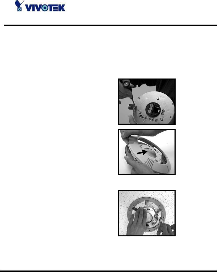
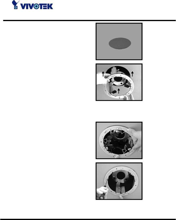
STEP 1
Screw the Fixing Plate to your dome body.
STEP 2
Remove the Hard Ceiling
Mount from the Decoration
Cover.
STEP 3
Attach the Mount to the ceiling. Mark the locations where all three ceiling holes should go.
STEP 4
Drill these holes on the hard ceiling.
- 6 -
www.vivotek.com
T: 886-2-82455282
F: 886-2-82455532
STEP 5
Fix the Mount with three screws.
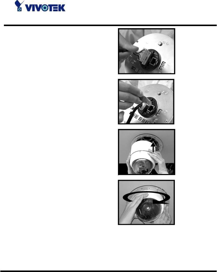
STEP 6
Connect the data cable through the center hole of the Mount to the dome body.
 NOTE: If use an IP dome, a network cable is needed other than the data cable.
STEP 7
Attach the dome body to the Mount and rotate the dome body clockwise. Tighten the fixing screw on the fixing plate.
- 7 -
www.vivotek.com
T: 886-2-82455282
F: 886-2-82455532
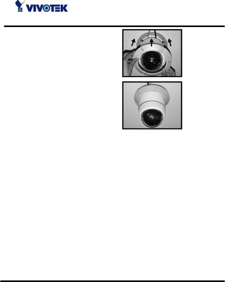
STEP 8
Assemble the Decoration
Cover to the Mount.
Completion
In-Ceiling Mounting
Here lists the items and tools needed to mount the dome camera into the ceilings. The supplied items are all in the dome camera package.
Items Needed:
1.Dome Camera
2.T-Bar (Accessory)
3.Red Sticker (Accessory)
4.50-cm Data Cable (Supplied)
5.Network Cable (for IP Dome---Self-prepared)
NOTE: The length of RJ-45 connector should be no longer than 2 cm.
Tools Needed:
1.Tool for cutting a circle on the ceiling
2.Screw Driver
Follow the steps to install the high speed dome camera for suspended ceilings.
- 8 -
www.vivotek.com
T: 886-2-82455282
F: 886-2-82455532
STEP 1
Place the Red Sticker on the ceiling plate, and cut the circle part out of the ceiling.
STEP 2
Put up the T-Bar into the ceiling hole.
 Note that the T-Bar wings should be inward when putting up the T-Bar into the ceiling hole, as shown in the picture.
STEP 3
Rotate the T-Bar’s wings to fix the T-Bar at the edge of the ceiling hole.
STEP 4
Tighten the screws on the wings.
- 9 -
www.vivotek.com
T: 886-2-82455282
F: 886-2-82455532
STEP 5
Connect the data cable to the dome body through the center hole of the bracket.
 Note: If use an IP dome, a network cable is needed other than the data cable.
STEP 6
Mount the dome body onto the bracket and rotate it clockwise.
- 10 -
www.vivotek.com
T: 886-2-82455282
F: 886-2-82455532
STEP 7
Assemble the Decoration
Cover to the T-Bar.
Completion
To install in Ethernet
Make sure the Ethernet is firmly connected to a switch hub. After attaching the Ethernet cable plug in the power adapter. If the LED turns out to be steady green after self-test, go to next paragraph “Software Installation”.
 Consult with the dealer of the peripherals for correct installation.
1 |
DI+ |
INPUT (Max. 50mA, 12VDC) |
|
||
2 |
DI- |
INPUT (Initial state of DI is low) |
|||
3 |
SW_COMMON |
OUTPUT |
(open |
from |
|
SW_OPEN at initial state) |
|
|
|||
|
|
(close with SW_OPEN when set DO |
|||
to ON) |
|
|
|
|
|
4 |
SW_NOPEN |
|
OUTPUT (Max. 1A, 24VDC or |
||
0.5A, 125VAC) |
|
|
|
|
|
- 11 -
www.vivotek.com
T: 886-2-82455282
F: 886-2-82455532
Software Installation
In this manual, "User" refers to whoever has access to the Network Camera, and "Administrator" refers to the person who can configure the Network Camera and grant user access to the camera.
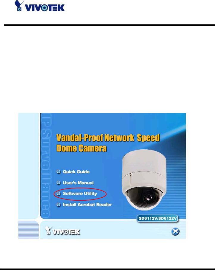
At the end of the hardware installation, the Administrator must place the product software CD into the CD-ROM drive of the PC running in MS Windows. An auto-run program will pop up (If the program is not on auto-run, go to the root directory of the software CD and click on “autorun.exe”).
Click on “Software Utility” item, after the window contains changed, click on “Installation Wizard” to run Vivotek’s installation program.
- 12 -
www.vivotek.com
T: 886-2-82455282
F: 886-2-82455532
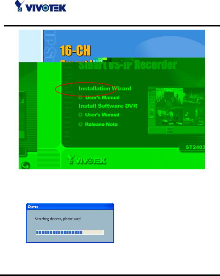
Upon Installation Wizard’s start up, a searching box will pop up. This program searches for Vivotek’s product on the same LAN:
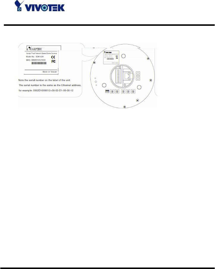
After searching, Vivotek Video Servers or Network Cameras will be located by the Installation Wizard. There may be several entries shown in the window. The Administrator may differentiate the Network Cameras with the serial number.
For the series number in the “Serial Number” field, please check the label on the bottom of the camera.
- 13 -
www.vivotek.com
T: 886-2-82455282
F: 886-2-82455532
The IP addresses shown in the "Current IP Address" field reflect those on the local network. They may be from the DHCP server. If there is no DHCP server, the camera will try to find a free IP address (this takes from 15 second to 3 minutes, depending on the LAN status). The method of finding IP address is seeking from 192.168.0.99, to 192.168.0.254. If any of the address inside this range is free, the Network Camera will be assigned to this IP address, and its subnet mask would be 255.255.255.0. If none of the addresses is free, the Network Camera will try the range from 192.168.0.2 to 192.168.0.98. After an IP address is assigned to the camera, the “Activity” status LED blinks.
The Vivotek’s new UPnP function will always assign an IP address for the Network Camera. The Administrator can click on button “Link to selected device” to connect the I.E. to the camera.
If the camera is not on the IP installer list, click on the “Search” button to search for the camera on the LAN.
- 14 -
www.vivotek.com
T: 886-2-82455282
F: 886-2-82455532

For more detailed usage of the Installation Wizard, please refer to the user’s manual of the Installation Wizard.
- 15 -
www.vivotek.com
T: 886-2-82455282
F: 886-2-82455532

Initial Access to the Network Camera
Installing Plug-in
For the initial access to the Network Camera in Windows, the web browser may prompt for permission to install a new plug-in for the Network Camera after a period of time of downloading. Permission request depends on the Internet security settings of the user’s PC or notebook. If the highest security level is set, the computer may prohibit any installation and execution attempt. This plug-in has been registered for certificate and is used to display the video in the browser. Users may click on  to proceed. If the web browser does not allow the user to continue to install, check the Internet security option and lower the security levels or contact your IT or networking supervisor for help.
- 16 -
www.vivotek.com
T: 886-2-82455282
F: 886-2-82455532
Check Network Settings
The Network Camera can be connected either before or immediately after software installation onto the Local Area Network. The Administrator should complete the network settings on the configuration page, including the correct subnet mask and IP address of gateway and DNS. Ask your network administrator or Internet service provider for the detail information. By default the Network Camera requires the Administrator to run installation every time it reboots. If the network settings are to remain unchanged, disable the Install option. Refer to “Network settings” on the System Configuration page for details. If any setting is entered incorrectly and cannot proceed to setting up the Network Camera, restore the factory settings following the steps in the “Troubleshooting” chapter of the Appendix.
- 17 -
www.vivotek.com
T: 886-2-82455282
F: 886-2-82455532

Add Password to Prevent Unauthorized Access
The default Administrator’s password is blank and the Network Camera initially will not ask for any password. The Administrator should immediately implement a new password as a matter of prudent security practice. Once the Administrator’s password is saved, the Network Camera will ask for the user’s name and password before each access. The Administrator can set up a maximum of twenty (20) user accounts. Each user can access the Network Camera except to perform system configuration. Some critical functions are exclusive for the Administrator, such as system configuration, user administration, and software upgrades. The user name for the Administrator is permanently assigned as “root”. Once the password is changed, the browser will display an authentication window to ask for the new password. Once the password is set, there is no provision to recover the Administrator’s password. The only option is to restore to the original factory default settings.
- 18 -
www.vivotek.com
T: 886-2-82455282
F: 886-2-82455532
How to Use
Authentication
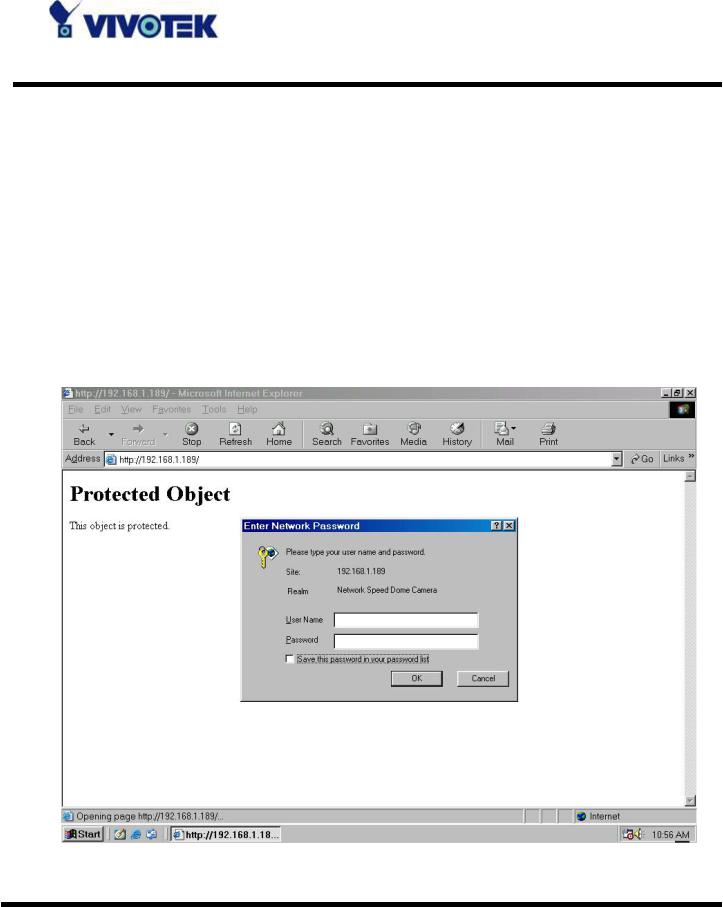
After opening the web browser and typing in the URL of the Network Camera, a dialogue window pops up to request a username and password.
The foreground is the login window and the background shows the message if authentication fails. The user may check the option box to save the password for future convenience.
- 19 -
www.vivotek.com
T: 886-2-82455282
F: 886-2-82455532

Primary User’s Capabilities
Main Screen with Camera View
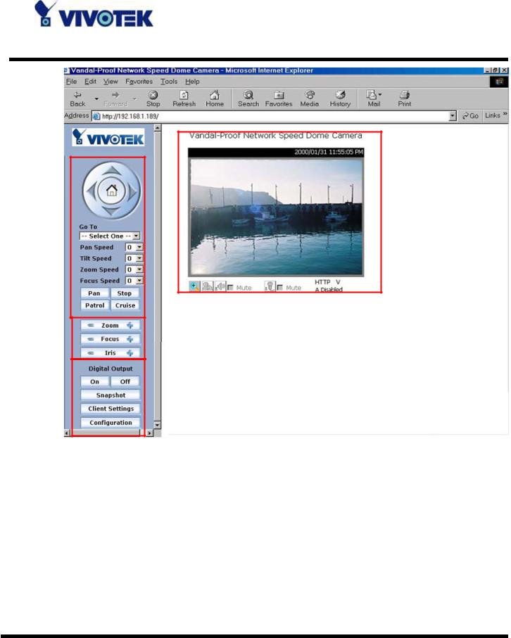
The main page layout has three parts:
Configuration functions: The camera can be configured using these user interfaces. Camera View: What the camera sees.
Pan/Tilt/Zoom control buttons: These buttons provide a command interface to control the aim of the camera.
CCD control buttons: These buttons provide a command interface to control the aim of the camera.
- 20 -
www.vivotek.com
T: 886-2-82455282
F: 886-2-82455532
The Configuration:
“Digital Output”
Clicking on the “On” or “Off” button turns the digital output to either on or off status.
“Snapshot”
Clicking on the “Snapshot” can get a JPEG format image of the current camera view in another window.
“Client Settings”
Clicking on this button links you to the client setting page, please check the following session for more details.
- 21 -
www.vivotek.com
T: 886-2-82455282
F: 886-2-82455532
“Configuration” Only the Administrator can access camera configurations.
The camera view
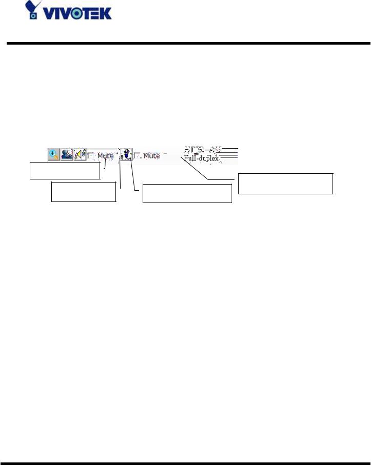
The information bar at the top of the camera view shows the assigned caption and the current date/time. The information bar at the bottom of the camera view shows the current streaming mode and audio transmission mode. You can push/toggle the talk button to talk to the remote server. The volume of speaker and microphone can also be adjusted.
Digital zoom
Microphone volume
Talk button |
Speaker volume |
The camera view provides not only the live video, but also a way to aim the Network Camera to different target. Using mouse to click on the target inside the video will command the Network Camera to aim at the target and with the mouse wheel up or down, the camera view will zoom out or in.
The pan/tilt/zoom control buttons:
The direction buttons are for Left, Right, Up, Down, and Home functions. The Home button centers the camera.
“Go to” Once the Administrator has determined the preset positions; the User can aim the camera using this control.
“Pan speed”
This selection box sets the moving range of the “Left” and “Right” commands. “Tilt speed”
This selection box sets the moving range of the “Up” and “Down” commands. “Zoom speed”
This selection box sets the moving range of the “zoom in” and “zoom out” commands.
“Focus speed”
This selection box sets the moving speed of the “focus near” and “focus far”
- 22 -
www.vivotek.com
T: 886-2-82455282
F: 886-2-82455532
commands. The focus function is obvious when the optical zoom time is larger than 7.
“Auto pan”
This button commands the camera to pan from the current position to the left-most and then to the right-most position. After panning, the camera returns to the original position.
“Auto patrol”
This button commands the camera to patrol between the preset positions on the Patrol List, which can be modified on the “Camera control page”. After one patrol cycle, the camera returns to the original position.
“Stop” This stops the “Auto Pan” command or “Auto Patrol” command.
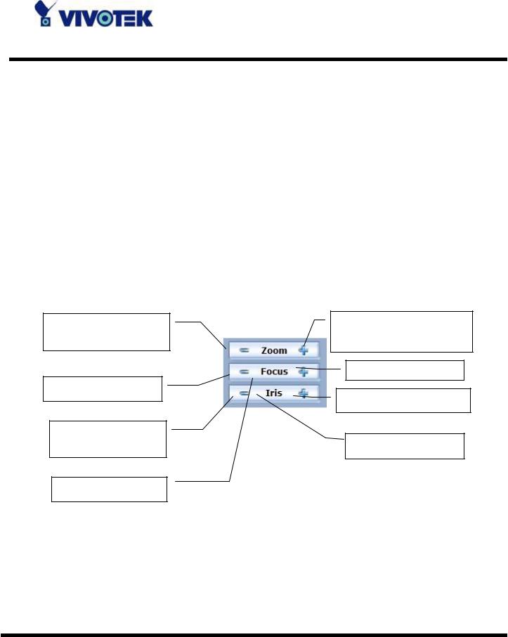
The CCD control buttons:
The set of the buttons is for controlling focus, iris and zooming.
Click to zoom widely |
Click |
to |
zoom |
|||
and see more. |
|
telescopically |
and see |
|||
|
|
|
|
Click to focus farer. |
||
Click |
to |
|
focus |
Click to set IRIS bigger. |
||
|
|
|
|
|||
Click |
to |
set |
IRIS |
|
|
|
smaller. |
|
|
Click |
to |
set auto |
|
|
|
|
|
|
||
Click |
to |
do |
auto |
|
|
|
- 23 -
www.vivotek.com
T: 886-2-82455282
F: 886-2-82455532
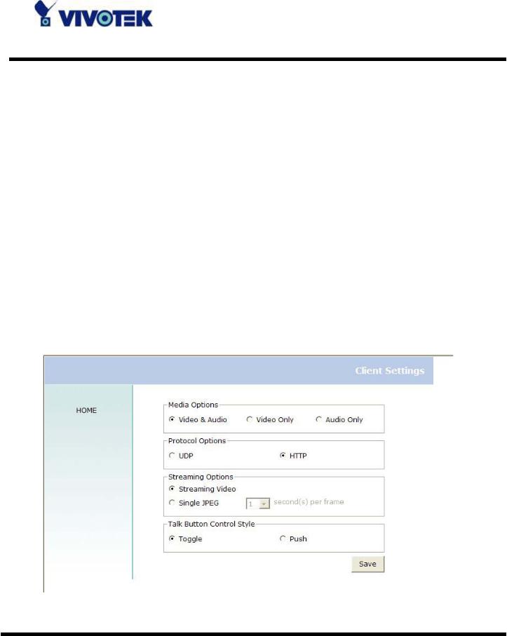
Client Settings
There are four settings for the client side.
Media Options - For the User to determine whether to receive video, audio or both. Protocol Options – Which allows choosing on connection protocol between client and server. There are two protocol choices to optimize your usage – UDP and HTTP.
The UDP protocol allows for more real-time audio and video streams. However, some packets may be lost due to network burst traffic and images may be obscured.
The HTTP protocol must be selected if the network is protected by a firewall which allows only HTTP Port (80) to be opened. If there is no restriction, UDP protocol is recommended. Generally speaking, the client’s choice will be in the order of UDP → HTTP. After the Network Camera is connected successfully, “Protocol Options” will indicate the selected protocol. The selected protocol will be recorded in the user's PC and will be used for the next connection. If the network environment is changed, or the user wants to let the web browser to detect again, manually select the UDP protocol and save, then return to HOME to connect to the Network Camera.
- 24 -
www.vivotek.com
T: 886-2-82455282
F: 886-2-82455532

Streaming Options – For users to select the video streaming types. Select “Streaming Video” options, the video connection will keep alive to enable you to see smooth video, while “Single JPEG” options will let you see the video in JPEG format by client periodic update the JPEG image from server according to the “Frame rate” settings.
Talk Button Control Style – For the User to determine whether to “click once and talk” or “push to talk”.
- 25 -
www.vivotek.com
T: 886-2-82455282
F: 886-2-82455532
Administrator’s Capabilities
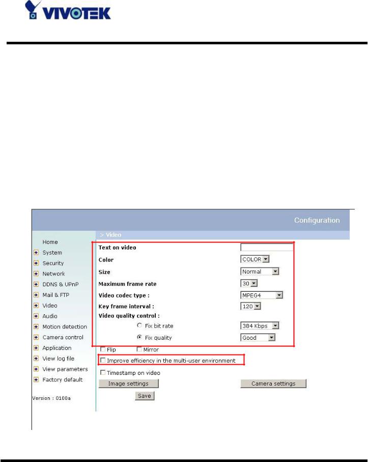
Fine-tuning for Best Performance
There are a few choices the Administrator is allowed to maximize the capabilities of the Network Camera. Best performance generally equates to the fastest image refresh rate with the best video quality, and at the lowest network bandwidth as possible. The six factors, “Size”, “Maximum frame rate”, “Video codec type”, “Key frame interval”, “Fix bit rate”, and “Fix quality” on the Video Configuration page, are correlative to allow for achieving the best performance possible.
- 26 -
www.vivotek.com
T: 886-2-82455282
F: 886-2-82455532
 Loading...