

Page 1

MS 3200
Operating Software
MO 3264
Owner’s manual and mounting instruction
Mode d’emploi et manuel d’installation
English
Bedienungs- und Einbauanleitung
Gebruiksaanwijzing en inbouwhandleiding
Istruzioni d’uso e d’installazione
Instrucciones de manejo y de montaje
Bruksanvisning och monteringsanvisning
Betjeningsvejledning og monteringsanvisning
User manual and installation instructions
www.vdodayton.com
Page 2

Attention!
Only use this system when it is safe to do so. It is more important to keep your eyes on
the road and your hands on the wheel.
Due to constantly changing traffic conditions, we unfortunately cannot guarantee 100 %
precision under all circumstances.
Attention !
N’utilisez le système que si vous ne mettez pas en danger votre vie ou celle des autres
usagers de la route. Il est plus important de surveiller le trafic routier et d’avoir les mains
sur le volant que de lire les informations apparaissant sur l’écran.
Étant donné que le sens de circulation a pu être changé entre temps, nous ne pouvons
pas vous garantir une exactitude à 100 % des indications données.
Achtung!
Benutzen Sie das System nur, wenn die Sicherheit es zuläßt. Es ist wichtiger, auf den
Verkehr zu achten und die Hände am Lenkrad zu lassen.
Aufgrund sich ständig ändernder Verkehrsführungen kann leider keine 100 %ige
Genauigkeit unter allen Umständen gewährleistet werden.
Belangrijk!
Gebruik het systeem uitsluitend, als de veiligheid het toelaat. Het is belangrijker om op
het verkeer te letten en de handen aan het stuur te houden.
Op grond van voortdurend veranderende verkeerssituaties kan helaas geen 100 %
nauwkeurigheid onder alle omstandigheden worden gegarandeerd.
Attenzione!
Usare questo sistema solo se il traffico lo ammette. E´ importante tenere d´occhio la
strada e le mani sul volante.
A causa dei cambiamenti continui della viabilità non si può garantire una precisione
assoluta in tutte le circostanze.
¡Atención!
Utilice el sistema sólo si lo permite el nivel de seguridad. Es más importante atender al
tráfico y mantener las manos en el volante.
Debido a que las rutas cambian constantemente, lamentamos no poder garantizar un
100 % de exactitud en cualquier ocasión.
Observera!
Använd systemet bara när säkerheten tillåter. Det är viktigare att iaktta vad som händer
i trafiken och hålla händerna på ratten.
På grund av den ständigt förändrade trafiksituationen kan ingen garanti för 100%:ig
noggrannhet under alla omständigheter lämnas.
Vigtigt!
Brug systemet kun, når De ikke bringer andre eller sig selv i fare. Vær opmærksom på
trafikken, og hold hænderne på rattet.
Pga. løbende ændringer i vejnettet kan der ikke opnås 100% overensstemmelse
mellem det digitale vejkort og den aktuelle trafiksituation.
Page 3
Page 4
1
2
3
Page 5
Page 6

CONTENTS
Contents
System Overview . . . . . . . . . . . . . . . . . . . . . . . . . . . . . . . . . . . . . . 2
NEW OPERATING SOFTWARE MO 3264 . . . . . . . . . . . . . . . . . . . . . . . . . . . 3
Safety instructions . . . . . . . . . . . . . . . . . . . . . . . . . . . . . . . . . . . . .3
New functions . . . . . . . . . . . . . . . . . . . . . . . . . . . . . . . . . . . . . . .4
New C-IQ functions . . . . . . . . . . . . . . . . . . . . . . . . . . . . . . . . . . . . 6
What else has changed in MO 3264? . . . . . . . . . . . . . . . . . . . . . . . . . . . 7
Tips for convenient operation . . . . . . . . . . . . . . . . . . . . . . . . . . . . . . . 8
MOUNTING INSTRUCTIONS . . . . . . . . . . . . . . . . . . . . . . . . . . . . . . . . . 9
GENERAL INFORMATION . . . . . . . . . . . . . . . . . . . . . . . . . . . . . . . . . . 17
Tips on the use of this manual . . . . . . . . . . . . . . . . . . . . . . . . . . . . . . 17
ATTENTION! Important notes for safe usage . . . . . . . . . . . . . . . . . . . . . . 17
How does the navigation system work? . . . . . . . . . . . . . . . . . . . . . . . . . 18
The digital road map . . . . . . . . . . . . . . . . . . . . . . . . . . . . . . . . . . . 19
C-IQ – INTELLIGENT CONTENT ON DEMAND. . . . . . . . . . . . . . . . . . . . . . . . 20
C-IQ – Your key to map, traffic and travel information . . . . . . . . . . . . . . . . 20
OPERATION . . . . . . . . . . . . . . . . . . . . . . . . . . . . . . . . . . . . . . . . . 23
LCD Monitor . . . . . . . . . . . . . . . . . . . . . . . . . . . . . . . . . . . . . . . 23
Remote control . . . . . . . . . . . . . . . . . . . . . . . . . . . . . . . . . . . . . . 23
Switching on / off . . . . . . . . . . . . . . . . . . . . . . . . . . . . . . . . . . . . . 24
Stand-by mode . . . . . . . . . . . . . . . . . . . . . . . . . . . . . . . . . . . . . . 24
Volume . . . . . . . . . . . . . . . . . . . . . . . . . . . . . . . . . . . . . . . . . . 24
MENUS . . . . . . . . . . . . . . . . . . . . . . . . . . . . . . . . . . . . . . . . . . . . 25
Cursor . . . . . . . . . . . . . . . . . . . . . . . . . . . . . . . . . . . . . . . . . . . 25
Scroll bars . . . . . . . . . . . . . . . . . . . . . . . . . . . . . . . . . . . . . . . . . 25
Character input . . . . . . . . . . . . . . . . . . . . . . . . . . . . . . . . . . . . . . 25
Main control menu . . . . . . . . . . . . . . . . . . . . . . . . . . . . . . . . . . . . 27
DESTINATION INPUT . . . . . . . . . . . . . . . . . . . . . . . . . . . . . . . . . . . . 28
Entering a destination address. . . . . . . . . . . . . . . . . . . . . . . . . . . . . . 28
Destination input menu . . . . . . . . . . . . . . . . . . . . . . . . . . . . . . . . . 28
Special destinations (POIs) . . . . . . . . . . . . . . . . . . . . . . . . . . . . . . . . 31
Destination input via GPS coordinates. . . . . . . . . . . . . . . . . . . . . . . . . . 32
VIAPOINTS . . . . . . . . . . . . . . . . . . . . . . . . . . . . . . . . . . . . . . . . . . 33
Via point input . . . . . . . . . . . . . . . . . . . . . . . . . . . . . . . . . . . . . . 33
GUIDANCE . . . . . . . . . . . . . . . . . . . . . . . . . . . . . . . . . . . . . . . . . . 35
Guidance screen . . . . . . . . . . . . . . . . . . . . . . . . . . . . . . . . . . . . . 35
Audible messages. . . . . . . . . . . . . . . . . . . . . . . . . . . . . . . . . . . . . 36
Route selection . . . . . . . . . . . . . . . . . . . . . . . . . . . . . . . . . . . . . . 38
Information during guidance . . . . . . . . . . . . . . . . . . . . . . . . . . . . . . 39
TRAFFIC INFORMATION . . . . . . . . . . . . . . . . . . . . . . . . . . . . . . . . . . . 41
Traffic information . . . . . . . . . . . . . . . . . . . . . . . . . . . . . . . . . . . . 41
DYNAMIC GUIDANCE WITH TMC. . . . . . . . . . . . . . . . . . . . . . . . . . . . . . 43
How TMC traffic announcements are made. . . . . . . . . . . . . . . . . . . . . . . 43
TMC traffic information on the guidance screen . . . . . . . . . . . . . . . . . . . . 43
Bypassing a traffic obstruction locally . . . . . . . . . . . . . . . . . . . . . . . . . . 44
Dynamic route planning . . . . . . . . . . . . . . . . . . . . . . . . . . . . . . . . . 44
1
Page 7

CONTENTS
ALTERNATIVE ROUTE . . . . . . . . . . . . . . . . . . . . . . . . . . . . . . . . . . . . 45
ADDRESS MANAGER . . . . . . . . . . . . . . . . . . . . . . . . . . . . . . . . . . . . 46
Address Manager . . . . . . . . . . . . . . . . . . . . . . . . . . . . . . . . . . . . . 46
EMERGENCY . . . . . . . . . . . . . . . . . . . . . . . . . . . . . . . . . . . . . . . . . 48
Emergency menu . . . . . . . . . . . . . . . . . . . . . . . . . . . . . . . . . . . . . 48
SYSTEM SETTINGS . . . . . . . . . . . . . . . . . . . . . . . . . . . . . . . . . . . . . . 49
Speed . . . . . . . . . . . . . . . . . . . . . . . . . . . . . . . . . . . . . . . . . . . 49
Guidance screen . . . . . . . . . . . . . . . . . . . . . . . . . . . . . . . . . . . . . 50
Dyn. route sett. . . . . . . . . . . . . . . . . . . . . . . . . . . . . . . . . . . . . . .50
Language . . . . . . . . . . . . . . . . . . . . . . . . . . . . . . . . . . . . . . . . .51
Volume . . . . . . . . . . . . . . . . . . . . . . . . . . . . . . . . . . . . . . . . . . 51
Date / Clock . . . . . . . . . . . . . . . . . . . . . . . . . . . . . . . . . . . . . . . . 51
Display. . . . . . . . . . . . . . . . . . . . . . . . . . . . . . . . . . . . . . . . . . . 52
Remote control . . . . . . . . . . . . . . . . . . . . . . . . . . . . . . . . . . . . . . 52
Measuring units. . . . . . . . . . . . . . . . . . . . . . . . . . . . . . . . . . . . . . 52
Mounting angle. . . . . . . . . . . . . . . . . . . . . . . . . . . . . . . . . . . . . . 52
Default settings . . . . . . . . . . . . . . . . . . . . . . . . . . . . . . . . . . . . . .52
Service . . . . . . . . . . . . . . . . . . . . . . . . . . . . . . . . . . . . . . . . . . . 52
System information. . . . . . . . . . . . . . . . . . . . . . . . . . . . . . . . . . . . 52
MAP CDs . . . . . . . . . . . . . . . . . . . . . . . . . . . . . . . . . . . . . . . . . . . 53
Notes on map CDs . . . . . . . . . . . . . . . . . . . . . . . . . . . . . . . . . . . . 53
Changing the map CD . . . . . . . . . . . . . . . . . . . . . . . . . . . . . . . . . . 53
MAINTENANCE & CARE . . . . . . . . . . . . . . . . . . . . . . . . . . . . . . . . . . . 54
Replacing batteries of the remote control . . . . . . . . . . . . . . . . . . . . . . . 54
Cleaning of the remote control and the monitor . . . . . . . . . . . . . . . . . . . . 54
Loading software updates . . . . . . . . . . . . . . . . . . . . . . . . . . . . . . . . 54
TROUBLESHOOTING. . . . . . . . . . . . . . . . . . . . . . . . . . . . . . . . . . . . . 55
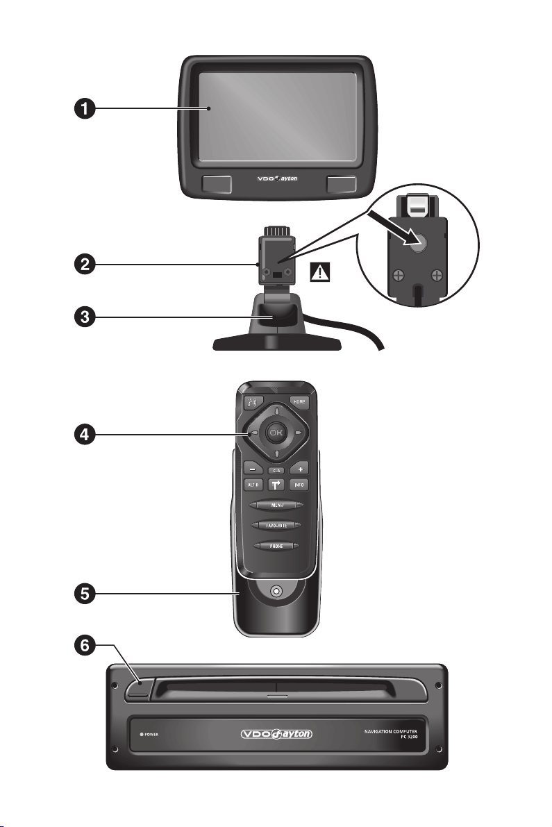
System Overview
On the illustration pages you can find an overview over the system components.
1 Detachable LCD monitor.
A
To remove the monitor, it is essential to press the unlocking button on the rear of
the monitor holder.
2 Unlocking button for monitor (concealed on the rear of the monitor connector).
Press release button on the back of the monitor support and gently pull upwards to
detach.
3 Monitor support, turnable and tiltable.
Press button on the support to tilt the monitor
4 Infrared remote control
5 Holder for remote control.
6 Eject CD. If ignition is switched off press key twice.
2
Page 8

NEW OPERATING SOFTWARE MO 3264
Safety instructions
The use of the navigation system by no means relieves the driver of his/her
A
responsibilities. The highway code must always be observed. Always observe the current
traffic situation.
The applicable traffic regulations and the prevailing traffic situation always take
A
precedence over the instructions issued by the navigation system if they contradict one
another.
For traffic safety reasons, use the navigation system menus only before starting a
A
journey or when the vehicle is stationary.
In certain areas, one-way streets, turn off and entry prohibitions (e.g. pedestrian zones)
A
are not recorded. In areas such as these the navigation system will issue a warning. Pay
particular attention to one-way streets, turn off and entry restrictions.
The navigation system does not take the relative safety of the suggested routes into
A
consideration. Road blocks, building sites, height or weight restrictions, traffic or weather
conditions or other influences which affect the route safety or travel time are not taken
into consideration for the suggested routes. Use your own discretion in order to decide on
the suitability of the suggested routes.
The current legal road traffic speed limit always takes priority over the values stored
A
on the data CD. It is impossible to provide an assurance that the speed values of the
navigation system will always match those of the current traffic regulations in every
situation.
Always observe the relevant legal speed limits and traffic regulations. The vehicle
speedometer must always be given priority for display of the vehicle speed.
A
Do not rely exclusively on the navigation system when attempting to locate an
emergency service (hospital, fire service, etc.). It cannot be guaranteed that all available
emergency services in your vicinity are stored in the database. Use your own discretion and
abilities to secure help in such situations.
3
Page 9

NEW OPERATING SOFTWARE MO 3264
New functions
The new operating software for your navigation system provides a number of new or
expanded functions:
Improved guidance
■
Improved visual and audible turn-off prompts thanks to additional symbols and
optimised voice-output characteristics.
Improved “Alternative route”
■
The settings range for planning an alterative route has been improved from only 10
km to up to 50 km.
Convenient resumption of guidance
■
Following a short stopover (ignition off) the navigation system can continue the
previous guidance upon request.
Additional route criteria “Avoid ferry” and “Avoid tunnel”
■
In addition to the previously available route criteria, “No toll road”, ferries and
tunnels can be deliberately avoided during route planning.
Availability of this function depends on the map data used. If route planning is not
✎
possible without the selected exceptions, toll roads, ferries and tunnels are included
in route planning.
■ Support of compressed map data
As of version 2004/02, the map and travel info content is compressed on the map CDs
in order to make further useful C-IQ content available to you.
The new map CDs can then only be read using this operating software version or
✎
higher.
■ Automatic mode for dynamic route planning
Fully automatic dynamic route planning allows you to concentrate on what is
important. The navigation system plans the route, taking into account the current
traffic situation without further notice.
Activate the “Automatic” option in the “Settings –> Dyn. route sett.” menu.
☞
When Automatic mode is activated, no information is displayed regarding present
✎
traffic problems. The route is always calculated based on the current traffic
situation received via TMC.
Automatic mode is switched off in the factory settings.
✎
4
Page 10

NEW OPERATING SOFTWARE MO 3264
Speed information
■
Display of the legal speed limit applicable to the current route segment in the
guidance screen, provided the map CD inserted supports this function. With an
additional audible warning, the reaching or exceeding of this speed limit is indicated
by means of an audible signal.
To activate display of the speed limit information in the guidance screen, proceed as
follows:
In the “Settings” menu , select “Guidance screen”.
☞
Activate the “Speed Info” option.
☞
The speed limit for the current route section stored on the map CD appears in the
✎
status field of the guidance screen.
If no speed limit value is included on the map CD for the current route section or if
✎
there is no speed limit, “--- km/h” is displayed in the guidance screen.
Availability of the legal speed limit depends on the map CD used and on the
✎
relevant country.
WARNING: No responsibility is accepted for the correctness of the speed limit
A
information provided by the navigation system; it may not always reflect the currently valid
regulations. Always observe the applicable legal speed limits and traffic regulations. The
vehicle speedometer must always be given priority for display of the vehicle speed.
■ Speed warnings
The navigation system offers two different options for speed warnings, provided the
map CD inserted supports this function:
The previously available warning, which can be set manually to a fixed speed value.
–
A visual and audible warning when reaching or exceeding the legal speed limits for
–
the route section currently being travelled along.
The speed warnings can be activated and configured as follows:
Select “Speed” in the “Settings” menu.
☞
1. Fixed speed limit:
Select “Limit (xx/h)” and set the desired limit for the fixed speed warning.
☞
Select “OFF,” if you wish to deactivate the speed warning.
☞
2. Legal speed limit:
Select “Speed info”, in order to activate the speed warning for the legal speed
☞
limit.
When the speed limit is reached, the symbol for the speed limit appears in the
✎
guidance screen with unfilled lines. As soon as the speed limit is exceeded, the
symbol appears filled in.
Availability of the legal speed limit depends on the map CD used and on the
✎
relevant country.
3. Audible warning:
Select “Aud. warning”, in order to activate or deactivate the audible speed
☞
warning for the speed limit.
A
WARNING: No responsibility is accepted for the correctness of the speed limit
information provided by the navigation system; it may not always reflect the currently valid
regulations. Always observe the applicable legal speed limits and traffic regulations. The
vehicle speedometer must always be given priority for display of the vehicle speed.
5
Page 11

NEW OPERATING SOFTWARE MO 3264
New C-IQ functions
Prepaid C-IQ
■
You can purchase country maps for navigation and/or travel info products (e.g. hotel
and restaurant guides) at a flat rate and in advance for use on a daily basis, but
without having to specify the actual days concerned. This means that you can always
have the correct data at your fingertips for making short trips abroad or taking a
weekend trip. With the “prepaid” service the information must be activated on the
calendar day on which it is to be used. Once you have purchased your prepaid days
from the C-IQ Service (www.C-IQ.net or 00800 99 33 33 33) they can be activated in the
navigation system in the normal manner by means of an access code. Please ensure
that the corresponding map CD has been inserted. For more detailed information
concerning this option contact the C-IQ Service.
Enter the activation code (access code) which you obtained for your prepaid C-IQ
☞
product.
For a description of code entry, refer to the operating, section “C-IQ - INTELLIGENT
✎
CONTENT ON DEMAND -> Activating content”, page 20.
Select “Prepaid C-IQ” in the “C-IQ” menu.
☞
Select “Prepaid Navigation” or “Prepaid Travelinfo”, depending on the type of
☞
C-IQ content you wish to activate.
The status of your prepaid content will be displayed. It indicates the number of
✎
remaining days of use.
You can access a list of content for the selected category via the L symbol.
☞
The “Z” symbol will take you back to the previous menu and you can access help
✎
for the current C-IQ topic by pressing “?”.
Select the product you require from the list in order to activate it for the current
☞
calendar day.
Information on C-IQ:
Code-entry for the activation C-IQ content only works when the map CD (CD-ROM) is
inserted.
For trouble-free use of C-IQ content, it is imperative that the current date is received
by the navigation system. This is only possible if at least one GPS satellite is being
received (see “GPS / Compass” information screen).
6
Page 12

NEW OPERATING SOFTWARE MO 3264
Info Points function
■
Visual and audible indication of important points along your route. Different
providers of travel and traffic information have optimised these specifically for
navigation systems. This includes information about fixed speed camera installations
or other safety relevant information (e.g. schools, kindergartens, etc.) and places of
interest to tourists. If you have activated such a product by means of a C-IQ access
code, the Info Points function can be activated and deactivated.
The Info Points function can be activated as follows:
In the “Settings” menu , select “Info Points”.
☞
Visual display of Info Points can be switched on using the “Active” option.
☞
When you approach an Info Point, the navigation system displays a corresponding
✎
message and detailed information on the appropriate point.
With the “Audible Warning” option, you can additionally activate an audible
☞
signal announcing an Info Point.
Using the Info Points function in conjunction with the fixed speed camera
✎
information will help you increase your awareness as you drive through areas which
have been classified by the authorities as particularly relevant to safety. Although
every care has been taken, comprehensive coverage cannot be guaranteed.
What else has changed in MO 3264?
■ Entering letters / Different input methods
(See page 25)
The database allows you to enter the different parts of compound city or road names
in varying sequence.
The input methods depend on the map CD inserted. Not all map CDs support this
✎
function.
■ Entering a new address
(See page 29)
The destination input functions via the postal code and Quick Access are not
✎
supported by all map CDs.
■
“Bypassing a traffic obstruction locally” and “Alternative Route”
(See pages 44 and 45)
In the preview screen for the alternative route, the L option is also available.
✎
“L” can be used to display a road list for the detour.
■
Dyn. route sett. (settings for dynamic route guidance)
(See page 50)
This setting is only possible when “Dyn. route” is activated in the route selection
✎
and a TMC station is received (via an optional TMC receiver).
■
Settings / language
(See page 51)
Some of the extended voice information may not be available for all voices. We
✎
therefore recommend only loading the voice designated as “new” in the desired
language from the software CD.
7
Page 13

NEW OPERATING SOFTWARE MO 3264
Settings / speed
■
(See page 49)
Setting of the SDVC mode has been moved from the “Speed“ menu to the
✎
“Volume“ menu.
Setting is as described under "Settings / volume", see below.
✎
Settings / volume
■
(See page 51)
The volume can be set gradually between “OFF“ and “24“. Voice messages are
✎
deactivated when set to “OFF“.
The SDVC mode can be set between “OFF“ and “4“.
✎
Tips for convenient operation
Cross-border guidance
■
Owing to the high data volume, the European navigation data is stored on several CD
ROMs (map CDs). In order to nevertheless achieve cross-border guidance, the most
important European cities and roads (Major Roads Europe) are additionally stored on
the map CDs at present. In order to enable cross-border navigation, the C-IQ content
must be activated for the destination and transit countries. Alternatively, route
planning can be performed without activation of this feature if the route is covered by
the connecting road network (Major Roads Europe). In this case, no visual and audible
guidance is available after crossing the border into a deactivated country.
For continuous cross-border guidance, it is imperative that the relevant C-IQ content
✎
is activated.
The following alternative input methods requiring the map data from two or more
map CDs are available for activating route planning:
Alternative 1:
Insert the map CD for the destination country. Start route planning and follow the
directional arrow displayed to the next digitised road. As soon as you have reached
the connecting road network, the directional arrow disappears and visual and audible
guidance begins.
Alternative 2:
Insert the map CD for your current location. Start route planning. Owing to the data
volume, you can only enter a destination which is covered by the connecting road
network. When approaching the destination, insert the map CD for the destination
country. Then enter details of the destination and start route planning again.
Please note that the connecting road network is used exclusively for route planning
✎
when the navigation CD of the actual location is not inserted.
Alternative 3:
Plan your travel route to a desired border crossing using the navigation CD ROM for
your current location. After crossing the border, insert the map CD of your current
location and start route planning to your destination or to the next border crossing.
8
Page 14

MOUNTING INSTRUCTIONS
IMPORTANT NOTES
Installation may only be carried out by trained specialists!
A
Observe all quality standards of the automobile industry!
A
Fire hazard! When drilling pay attention to the location of cable harnesses, tank and
A
fuel pipes!
Never drill into car parts which are load bearing or are important for safety reasons!
A
When installing components in the interior of the car remember the following:
The driver’s field of vision must not be obstructed!
A
Increased risk of injury in accidents! Do not mount components in an area where the air
A
bag will inflate or where head or knees could impact in the event of an accident!
Installation may only be made in vehicles with 12 V board voltage and negative pole on
A
car body. Installation in unsuitable vehicles could result in malfunction, damage or fire!
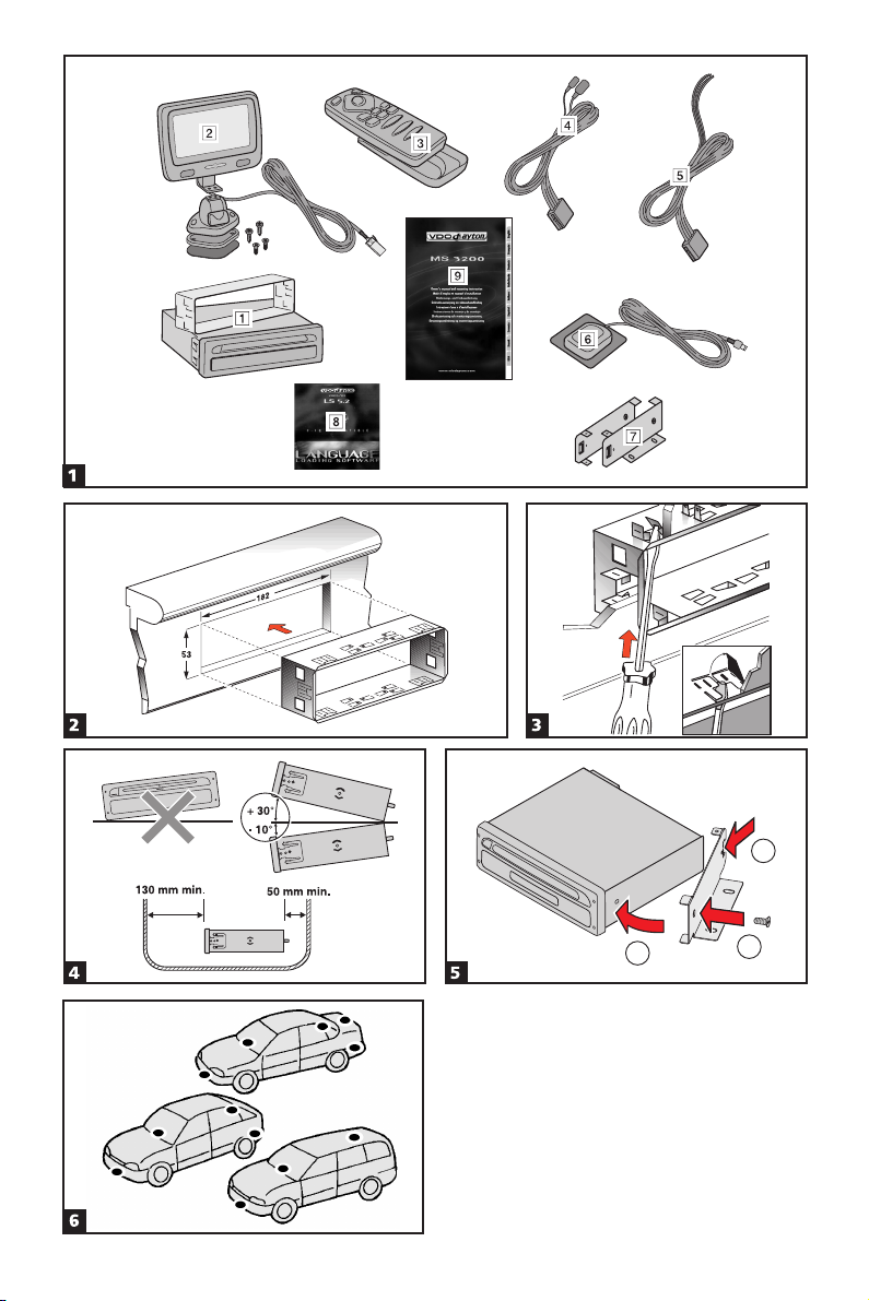
Checking the scope of delivery, ill. 1
1 Navigation computer with mounting sleeve and 2 mounting hooks
2 Monitor, monitor connector with cable, monitor holder with mounting plate,
double-sided self-adhesive tape and 4 screws
3 IR remote control with holder
4 Signal cable
5 Power supply cable
6 GPS antenna with metal plate and cable
7 Mounting brackets and installation material
8 Language Loading Software CD
9 Instructions for use and mounting instructions
Take safety precautions
A
Before starting work disconnect the negative car battery terminal! When doing so
make sure to observe manufacturer’s safety instructions (alarm system, air bag,
immobilizer, radio coding, etc.)!
9
Page 15

MOUNTING INSTRUCTIONS
Installing metal sleeve, ill 2 - 3
The computer can be mounted in a DIN radio opening of the vehicle with the supplied
metal sleeve.
Please note before mounting, ill. 4:
■
To ensure access to the CD opening a free space of at least 130 mm has to be in
–
front of the navigation computer.
For sufficient air circulation a free space of at least 50 mm has to be behind the
–
navigation computer.
The computer must be installed horizontally. Deviations of - 10 to + 30 degrees can
–
be set in the “Mounting angle” menu (see “Initial operation”). Larger deviations
may result in malfunctions.
A stable connection to the car body is necessary for the computer to function
–
correctly!
Insert metal sleeve into the DIN opening and press appropriate tags outwards with a
screwdriver. Take care not to damage hidden parts in the dashboard.
Securing the computer using the mounting brackets
If installation of the navigation computer in a DIN slot is impossible or undesirable, it
can be installed in alternative installation locations using the supplied mounting
brackets (e.g., in the glove box, in the luggage compartment or under the seats).
For this purpose, both side-mounted catch springs must be removed from the
navigation computer. The two Torx screws are required later for securing the
mounting bracket.
■ Attaching mounting brackets, ill. 5
1. Position the brackets with the punched out tab at the right (or left) rear edge of the
computer housing. It must be ensured that the tab fully engages with the sheet
metal of the computer housing.
2. Swing the bracket forwards, applying pressure to the rear edge of the bracket so that
it is flush with the computer housing.
3. Fasten the brackets to the computer housing using the existing Torx screws.
The computer can then be secured in the desired installation location using the screws
supplied.
■
Suspended installation
If suspended installation is required for the computer (e.g., under the rear shelf), the
mounting brackets can be attached to the computer in the reversed position.
Installing holder for the remote control
The remote control holder can either be screwed in place with the supplied angle
bracket or glued onto the mounting surface with the supplied adhesive tape.
Note: Mounting temperature should be at least 15 degrees centigrade to ensure the
full adhesive effect of the tape.
10
Page 16

MOUNTING INSTRUCTIONS
Installing GPS antenna, ill. 6
The GPS antenna can be mounted in the vehicle interior, for example on the
dashboard or on the hatshelf. The antenna must have clear “view” of the sky.
In vehicles with metallic window tinting, the GPS antenna should be mounted in an
✎
area without tinting or outside on the vehicle body, for example in the plastic
bumper.
Mount the antenna with the supplied double-sided adhesive tape.
–
Notes: To ensure perfect function please keep a distance of at least 10 cm to metall
parts like window frame.
The mounting temperature should be at least 15 degrees centigrade to ensure the full
adhesive effect of the tape.
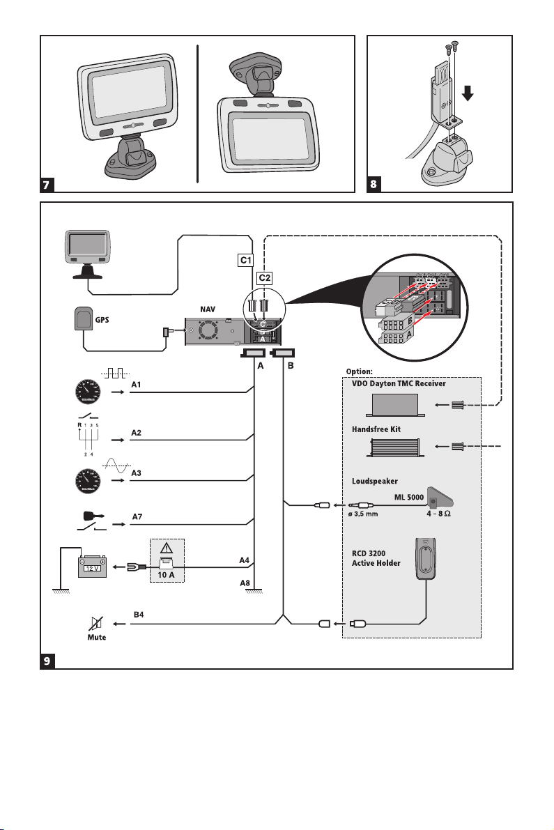
Mounting monitor, ill. 7 - 8
Never install the monitor in an area where the head could impact in case of an
A
accident!
The monitor can be fastened with the supplied support either in normal or in
suspended position. If it is mounted in suspended position, make sure that the display
contents is rotated 180 degrees (“System settings” menu, option “Display”).
■ Glueing the support
1. Fix the mounting plate with two Phillips head screws to the bottom of the monitor
support.
2. Install monitor connector with the two countersunk screws to the monitor support,
see ill. 8.
3. Slide monitor on the connector until it clicks into position.
4. Determine the mounting position of the monitor.
5. Remove the monitor from the support.
CAUTION: When removing the monitor from the support, always make sure to press
the release key on the rear of the connector!
6. Clean the surface from grease and dust with methyl alcohol.
7. Remove protective paper from one side of the supplied adhesive tape and stick it to
the bottom of the mounting plate.
8. Remove protective paper from the lower side of the adhesive tape and place the
monitor support onto mounting surface and press firmly.
Note: Mounting temperature should be at least 15 degrees centigrade to ensure the
full adhesive effect of the tape.
■
Screwing the monitor support
Screw monitor support without mounting plate directly in place with two appropriate
screws.
■
Alternative mounting
To extend the mounting possibilities you can also mount the monitor without the
supplied support:
Directly stick the monitor on the dashboard with double-sided self-adhesive tape.
For alternative mounting different supports are available in the high street.
A
Observe safety warnings concerning driver’s sight and air bag inflation area!
11
Page 17

MOUNTING INSTRUCTIONS
Completing electrical connections, ill. 9
Lay all cables carefully. Refer to the connecting diagram on the fold-out page at the
end of the booklet and to the table below.
Power supply cable (ISO connector A):
Pin no. Cable colour Connection
A1 black/white speedometer signal input, digital (long wire)
A2 white/yellow back-up lights (reversing signal)
A3 white/brown speedometer signal input, analogue (short wire)
A4 red +12V permanent power supply, “terminal 30” (via cable fuse 10 A if
A7 violet +12V switched, “terminal 15” (must not be interrupted during engine start)
A8 brown negative battery pole, “terminal 31”
Only connect electrical signals to appropriate terminals in the vehicle.
A
In the case of a direct connection to the battery secure the positive connection (red
A
lead) with a 10 A fuse close to the battery (approx. 10 - 15 cm).
1. Connect the free cable ends A4, A7 and A8 of the power supply cable 5 to suitable
terminals in the vehicle according to the connecting diagram and the table.
2. Do not cut off unused cables! Wind them together and tie them back! They may be
used later to install additional features.
■ Speedometer signal (ISO connector A):
Depending on the type of speedometer signal, either the digital (A1) or the analogue
(A3) input must be selected. Check speedometer signal using an oscilloscope if
necessary.
A
Never tap the speedometer signal from the ABS control!
Digital (standard):
Connect the black/white cable A1 from cable harness to the tapping position of the
speedometer signal. Location and connection details can be found in the vehicle
specific information sheets (available as CD ROM).
Note: Many cars are supplied with the speedometer signal on one of the car radio
connectors. Ask your car dealer for more information or call our hotline.
Analogue (for retrofitted speedometer senders and magnetic sensors):
Connect the short black/white A3 cable (directly at ISO chamber A connector) of the
wiring harness to the output of the speedometer sensor or the magnetic sensor.
■
Further signals (ISO connector A):
Connect the white/yellow cable (A2) to a suitable connecting point of the back up
lights (positive pole of the reversing lamp).
necessary)
12
Page 18

MOUNTING INSTRUCTIONS
Connecting system components (ISO connector B)
Remote control holder RCD 3200 (accessory):
Connect the Mini DIN plug of the remote control cable to the socket on the signal
cable harness 4.
Loudspeaker (accessory):
Connect the loudspeaker (optional accessory ML 5000) with the 3.5 mm jack to the
3.5 mm plug of the signal cable harness 4.
The loudspeaker impedance should be between 4 and 8 Ohms.
Installing loudspeaker mute function (optional)
Connect the white/brown cable (B4) of the signal cable 4 to the mute input of the car
radio.
TMC extension (ISO connector C2):
■
For system enhancement, an optional VDO Dayton TMC receiver can be connected to
the navigation computer. For connection details see “Mounting the navigation
computer”.
Hands-free unit (ISO connector C1):
■
A VDO Dayton hands-free unit can additionally be connected to the navigation
computer. For connection details see “Owner's manual and mounting instructions
MG 3000 M”.
■ Reproduction of voice messages through vehicle speakers
For reproduction of the guidance messages by the left front speaker of the vehicle you
can connect an adaptor cable MA 1300 (optional) between the loudspeaker connector
and the audio output of the navigation computer.
Mounting the navigation computer
1. Connect the GPS antenna.
2. Connect power supply cable 5 to ISO connector A’ at the navigation computer.
3. Connect signal cable 4 to ISO connector B’ at the navigation computer.
4. Insert yellow plug C1 of the monitor cable into the left chamber of ISO connector C1’
at the navigation computer.
5. If you want to connect system extensions, take care to slide all the C plugs together
before connecting them to ISO connector C’ at the navigation connector.
Green plug C2 of the TMC extension (optional): middle part (C2) of ISO connector C2’
6. Screw the rubber buffer onto the rear support stud of the navigation computer and
slide the computer into the metal sleeve until it clicks into position.
Caution: First mount the navigation computer firmly, then make the connection to
the vehicle’s power supply. Otherwise a wrong calibration of the gyro sensor may
result.
13
Page 19

MOUNTING INSTRUCTIONS
Initial start-up
1. Reconnect the car battery.
2. Restore perfect functioning of the electrical system (clock, onboard computer, alarm
system, air bag, immobilizer, radio coding, etc.).
3. Switch on the ignition.
4. Insert map CD into the navigation computer. Please note the instructions regarding
activation of C-IQ map, travel and/or traffic info, see the operating instructions,
Section “C-IQ INTELLIGENT CONTENT ON DEMAND” on page 20.
5. Insert batteries (not supplied) in the battery compartment of the remote control (see
user manual of the navigation system).
If an RCD 3200 active holder (accessory) is used for the remote control, the remote
control also works without batteries when placed in the holder.
6. Park the car so that the GPS antenna has free “visual contact” to the sky.
7. Start the engine.
The monitor display appears (user advice).
8. Confirm the user advice by pressing OK key on the remote control.
The start menu appears, initialization of the navigation computer then begins
(duration between 2 and 10 minutes).
Setting mounting angle
■
In order to ensure perfect functioning of the system, the computer must be adjusted
to the actual installation angle (e.g., in the dashboard).
1. Select the “Mounting angle” option from the “System settings” menu.
2. Depending upon the installation, set the angle to between - 10 and + 30 degrees.
The system does not differentiate between negative and positive angles. Thus, even
for a mounting angle of, e.g. - 10 degrees, set a value of “10” in the menu.
Checking the car functions
A
Only check safety functions when the car is standing still or driving at low speed!
Always carry out checks in open areas!
Check brake system, alarm system, lights, immobilizer, speedometer, trip computer,
radio (coding) and hi-fi stereo, clock.
Checking the navigation functions
Check the following functions when the car is stationary:
Remote control (batteries inserted)
Press the keys on the remote control and check operation.
GPS reception
Enter a destination and select “Guidance”. Call up the “GPS/Compass” information
menu via the guidance screen (see operating instructions) and check the number of
satellites. For a sufficiently exact location determination the number should be
between 4 and 8.
14
Page 20

MOUNTING INSTRUCTIONS
Calibrating the system
For automatic calibration, perform a short test drive (approx. 10 minutes) on digitised
roads. Change direction several times.
Drive through several intersections and monitor the current vehicle position in the
“Car position” information menu. Once the displayed position agrees with the
actual car position, calibration is complete.
Note: The system can also be calibrated without C-IQ contents activated. However, no
directional information will be provided. The current vehicle location can then be
checked in the emergency menu (see operating instructions, page 48).
Hotline
Hotlines are available in many countries to handle queries about the VDO Dayton
multimedia systems. Up-to-date telephone numbers can be found in the accompanying
info sheet.
Subject to technical modifications and errors.
15
Page 21

MOUNTING INSTRUCTIONS
16
Page 22

GENERAL INFORMATION
Tips on the use of this manual
To make reading this manual easier you are given the following aids:
Prompts you to do something.
☞
Shows you the reaction of the set.
:
Provides additional information.
✎
Marks an enumeration.
–
Shows that the current topic is continued on the following page.
6
This is a security or warning advice. It contains important information on the safe use
A
of your navigation system. In case of disregard of this advice the danger of material
damage, injury or even death may result. Please observe this advice carefully.
ATTENTION!
Important notes for safe usage
The usage of the navigation system does not exempt the driver from his
A
responsibilities. Pay attention to the local traffic regulations. Watching the road is more
important than watching the display!
If the current traffic situation and the advice of the navigation system are in
A
contradiction, traffic regulations always have priority over advice given by the system.
A
For driving safety data entries should only be made when the car is stationary.
A
In some areas it is possible that not all road information is covered. Restrictions
regarding entry into pedestrian precincts, driving direction of a one way street and turning
restrictions are not given. In these areas the navigation system gives a warning. Always
obey road signs and traffic regulations.
17
Page 23

GENERAL INFORMATION
How does the navigation system work?
The position and movements of the
80
60
100
120
40
140
20
0
160
054.346.3
Speedometer
signal
Gyroscope
Navigation
computer
GPS signal
Digital roadmap
Important notes on the function of your navigation system
In principle, the system is functional with poor GPS reception, although the accuracy of
the positioning may be impaired by poor or interrupted GPS reception or errors can
occur in the determination of the position, which result in incorrect position reporting.
Start-up characteristics
vehicle are recorded by the navigation
system’s sensors. The distance travelled is
determined by the vehicle speedometer
signal, rotary motion in curves is detected
by a gyro sensor (inertial compass). The
position is determined via the GPS (Global
Positioning System) satellites.
The position can be calculated within a
range of approx. 10 m by comparing the
sensor signals with the digital map on the
navigation CD.
If the vehicle is parked for longer periods of
time, the satellites continue their orbit. After
the ignition is switched on, it may take several
minutes until the navigation system receives
signals from sufficient satellites for evaluation.
During the start-up sequence, it is possible that the navigation system will report:
“You are leaving the digitised area”. The navigation system assumes that the vehicle is
located outside a digitised area. If other roads exist in this area, the navigation system
may issue incorrect messages. The navigation system assumes that the vehicle is located
on another road.
Comments
After transport of the vehicle by train or ferry, the navigation system may require a
few minutes for exact positioning.
After disconnecting the vehicle battery, up to 15 minutes may be required for exact
positioning. For this, the vehicle must be outdoors and the system must be switched
on in order to receive transmissions from the GPS satellites.
18
Page 24

GENERAL INFORMATION
The digital road map
To be able to plan a route to a destination address, the navigation system not only
requires the current position of the vehicle but also a digital road map containing the
destination address itself and the roads leading to the destination address. This digital
road map is on the map CD which you insert into the navigation computer.
Real road network Line pattern of digitized map
The road system is stored on the map CD as a line model, i.e. even large junctions have
only one focal point that is approached by all roads in point-to-point fashion. Thus the
navigation system indicates the distance to the turn-off point as the distance to the
centre of the junction. This is why the distances indicated on main road signs may not
agree with those of the navigation system. The road signs indicate the distance to the
beginning of the exit.
Areas with limited road information
In some areas, not all of the information on a road is available on the map CD. Thus,
for example, turn-off prohibitions, information on the direction of travel in a one-way
street or prohibited entry into a pedestrian zone may be missing. The navigation
system will display a warning if you drive into such an area. Local traffic laws always
take precedence over navigation system instructions. Always observe the road signs
and motor vehicle traffic regulations.
Topicality of the map CD
Roughly 10 - 15% of the road system characteristics change each year. Due to these
constantly changing traffic conditions (construction of new roads, traffic calming, etc.)
we cannot guarantee that the digital road map will be in 100 % agreement with existing
traffic conditions. We recommend that you always use the most current version of the
map CD for navigation.
19
Page 25

C-IQ – INTELLIGENT CONTENT ON DEMAND
C-IQ – Your key to map, traffic and travel
information
Your navigation system is supplied with a CD containing the latest version of the map
software along with travel and traffic information (for dynamic navigation). The
information on the CD is encrypted and can be partially or completely activated for a
defined period with the aid of an access code. Your advantages:
You only pay for the information that you actually use.
–
You only pay for the time that you actually use.
–
After the first activation, you will automatically receive subsequent CD updates.
–
You always have the latest information.
–
You can get hold of the activation easily via the Internet, by calling our free hotline
–
or from your dealer.
Activation options
The CD contains the latest version of the road map software. It also contains travel guide
information for a number of countries as well as traffic information for dynamic route
planning via TMC (in countries which offer this service).
You can activate
the road data
–
individual travel guides and if required
–
traffic information
–
in a number of countries for a certain period of time (see also the preview in this
chapter). Your C-IQ Service will be happy to provide more information about the
possible access options. You should also read the C-IQ brochure supplied with your
map CD.
Registering the navigation system
In order to activate C-IQ products, you must register your navigation system with
C-IQ Service. Registering the system also provides you with additional anti-theft
protection. If a unit is registered with C-IQ Service as stolen, C-IQ Service will not issue
any new activation codes for C-IQ contents.
To register your navigation system, you need the Navi ID. In a small number of cases
the Initial ID or version number of your map software is also required.
You can access this data as follows:
In the main control, select “C-IQ”.
☞
Select “Navi ID”.
☞
The 8-digit Navi ID, the map CD currently loaded
:
and the version number of the navigation
software are displayed.
To read out the Initial ID, move the cursor to
☞
“Initial ID” and confirm your selection by
pressing OK.
The “Z” symbol will take you back to the previous menu and you can access help
✎
for the current C-IQ topic by selecting “?”.
Make a note of the Navi ID. You can now contact C-IQ Service and register your
☞
system.
20
Navi ID: 8Q6S 7ED4
CD EUR 2003/01 NT
SW ID: 0046
Navi ID
Initial IDZ ?
Page 26

C-IQ – INTELLIGENT CONTENT ON DEMAND
Activating products
Once you have received your activation code, enter it into the system.
For activation and revocation of C-IQ contents, the navigation system must have
A
sufficient GPS reception during the code input, because time and date information are
needed for activating the C-IQ access code. If necessary, check the GPS reception in
information menu “GPS / Compass”. The number of satellites received should be at least 3.
See page 40.
In the main control menu, select “C-IQ” then
☞
“Code Input”.
The cursor appears automatically on the first digit
☞
of the code.
Press OK to activate each digit in the code.
☞
Next, use the cursor keys to select the correct code
☞
digit and confirm your selection by pressing OK.
You may change any of the code digits at any time
✎
by moving the cursor to the required position in
the code and pressing OK.
Once the code is complete, the cursor will automatically move to “OK”. Confirm by
☞
pressing OK.
Once you have entered a correct code, the system will display information about
☞
the C-IQ products you have just activated.
The system will inform you if an incorrect code has been entered, and/or if your
✎
system software is not capable of processing the encrypted information.
In these cases, select either “OK”or “C-IQ Service”, if you wish to establish contact,
☞
and press the OK key.
It is possible to operate the system without activation. Destinations can be entered.
Navigation information, however, will only be provided for activated areas and for
activated services.
Code Input
8QR5-Z4AK
G __-____6
OK Quit ?
My C-IQ
You have the choice of obtaining information about your activation status at any
time.
Select “My C-IQ” in the “C-IQ” menu.
☞
Select “Active products” if you wish to find out more about the products you
☞
have activated.
Select “Starting soon” if you wish to view details of products you have received
☞
which will soon be active.
Select “Expiring soon” if you wish to find out which service products you currently
☞
have in use and for how long they will continue to be available.
Select “Revocated products” to view a list of products which have been revocated.
☞
21
Page 27

C-IQ – INTELLIGENT CONTENT ON DEMAND
Preview
Together with your map and travel information software you will also receive the
opportunity to inspect different products free of charge before ordering them.
You can have the system display the status of this preview:
Select “Preview” in the “C-IQ” menu.
☞
You will see the status of your preview options. It contains the number of map and
:
travel information products that you are still able to test free of charge.
You can access a list of possible preview products via the L symbol.
☞
Select the product you require from the list in order to test it for the period of time
☞
indicated.
C-IQ Settings
Set up your system so that you are informed about the status of your activated C-IQ
products automatically and in good time:
Select “C-IQ Settings” in the “”C-IQ“ menu.
☞
Select the number of days (between 1 and 10) you wish to be informed in advance
☞
of the expiry or start of the products you have activated.
You can use “Expiring soon” and “Starting soon” to select whether you wish to
☞
be informed in advance and, if so, which products you wish to be informed about.
Select “Return” to go back to the previous menu.
☞
If you wish to be informed about the expiry or start of C-IQ products when the
✎
system starts up, you can view a list of corresponding products via the L symbol.
C-IQ Info
Here you will find general information about the C-IQ products on the map CD you
have loaded.
Select “C-IQ Info” in the “C-IQ” menu.
☞
This option is only supported by certain map CDs.
✎
C-IQ Service
Here you will find information about your C-IQ Service:
Select “C-IQ Service” in the “”C-IQ“ menu.
☞
Select “Z” to go back to the previous menu.
☞
Select “P C-IQ” to establish telephone contact with the C-IQ Service Centre.
☞
The “P C-IQ” option is only active if a telephone module is connected to the
✎
navigation system (this function is in preparation).
22
Page 28

OPERATION
LCD Monitor
If mounted with the supplied support, the monitor can be removed from the holder
for advanced theft protection.
Removing the monitor
Press the release button on the back of the support and gently pull the monitor
☞
upwards.
Do not push on the display screen to avoid damage of the LCD.
A
Installing the monitor
Gently slide the monitor onto the support until it clicks into position.
☞
Adjusting the monitor
If mounted on the supplied support, the monitor can be adjusted to your viewing
angle.
Turn the monitor until the best angle of view is reached.
☞
Press the release button on the monitor support to tilt the monitor to its best
☞
position.
Remote control
The VDO Dayton Navigation System is controlled by an infrared remote control.
Gently pull the remote control forward to release it from the holder.
☞
A
Before driving off, slide the remote control back into the holder until it clicks into
position.
The keys on the remote control have the following functions:
{. . . . . . . . . . Play back current guidance advice and (if available) the current
. . . . . . . . . . . . TMC message.
HOME . . . . . . . Retrieve the “Home” address and activate guidance.
8 . . . . . . . . . . Cursor key upwards; select options.
4 . . . . . . . . . . Cursor key left; select options.
6 . . . . . . . . . . Cursor key right; select options.
2 . . . . . . . . . . Cursor key downwards; select options.
OK . . . . . . . . . OK key; confirm a selection.
-. . . . . . . . . . Decrease voice volume of guidance advice.
+. . . . . . . . . . Increase voice volume of guidance advice.
CLR. . . . . . . . . Delete the last entry / back to previous menu.
ALT-R . . . . . . . Plan an alternative route.
_. . . . . . . . . . Activate guidance / switch to guidance screen.
INFO . . . . . . . . Open the menu “Special dest. –> Info on car pos.“.
MENU . . . . . . . Show main control menu.
FAVOURITE. . . Programmable function key. See page 52.
PHONE . . . . . . Open the phone menu (only if a VDO Dayton hands-free unit is
. . . . . . . . . . . . connected).
23
Page 29

OPERATION
Active remote control holder RCD 3200 (optional accessory)
■
If you use your remote control in the optional holder RCD 3200, the internal batteries
are not used.
When the batteries are exhausted the navigation system may no longer react on key
presses.
Slide the remote control into its holder to resume normal operation.
☞
Replace the batteries. Battery replacement see page 54.
☞
Switching on / off
The navigation system is switched on / off together with the ignition.
Switch on the ignition.
☞
As soon as the navigation system is operable, an advice on the use of the system
:
appears on the display.
Read and confirm this advice by pressing OK on the remote control.
☞
The “Main control” menu appears.
:
After a few seconds the system is initialized and you can select the navigation
functions (options in highlighted letters).
Stand-by mode
You can switch the system to its stand-by mode as follows:
Select “Stop guidance” from the main control menu.
☞
The display is switched off and audible guidance advice is muted.
:
Press one of the cursor keys 4, 6, 8, 2 or the OK key on the remote control to
☞
resume normal operation.
If the navigation system was switched off in stand-by mode, it restarts in stand-by
mode when turning the ignition on again.
Volume
You can adjust the volume of the audible guidance advice as follows:
Press the + key once or more than once to increase the volume of the voice
☞
messages.
Press the - key once or more than once to decrease the volume of the voice
☞
messages.
The adjusted volume is announced.
:
The volume can be set so that the volume is increased depending on the driving
✎
speed. See “System Settings”, page 51.
24
Page 30

MENUS
Cursor
The cursor is used to select menu options or
characters. It is shown as white characters on black
background.
For moving the cursor use the cursor keys
☞
8, 2, 4 or 6.
Confirm your selection by pressing the OK key.
☞
The cursor is briefly displayed as a frame around
:
the selected field.
Options currently not available are shown in faint.
System settings
Guidance screen
Dyn. route sett.
Language
Volume
Scroll bars
In all menus a scroll bar is displayed on the left
margin of the screen which shows you the position of
the cursor within the current menu.
Move the cursor to a menu option on the upper or
☞
lower margin of the screen using the cursor keys
8 or 2.
Continue pressing the same key.
☞
Further menu options are shown automatically.
:
Except for in the main control menu the menu title changes into the “Return” option
as soon as you move the cursor to the upper edge of the screen.
Confirm “Return” with the OK key to exit the menu,
☞
or:
press cursor key 8 again to move further up within the menu.
☞
Guidance screen
Dyn. route sett.
Language
Volume
Return
Character input
Names are entered by selecting characters from a list.
This kind of character entry will simply be called
“typewriter” further on in the manual.
To select a character place the cursor on the
☞
desired character by using the cursor keys 4, 6, 8
and 2.
Confirm your selection by pressing the OK key on
☞
the remote control.
Characters which are not available are shown as dots and are skipped automatically.
✎
Characters entered by mistake can be deleted by pressing the CLR key.
✎
City:W_
A...E... .....O..
I
...U...Y...
g
¡‰
¯Z ®–
25
Page 31

MENUS
Options when entering characters
The bottom line of the display shows command icons with which you can carry out the
following functions:
c : Display and selection of destination country (in this case, “D” for Germany).
ƒ : Save an address in the personal address book.
‰ : Jump to menu “Special dest.”. See page 31.
¡ : Delete the character entered last.
Š : Direct input of road name without previously entering the name of the city
(depending on map CD).
© : Cancel entry and return to the start of the destination entry.
¯ : Display a list of database items.
® : End of destination input and automatic start of guidance.
– : Confirm the last entered data and go to the next data entry option.
o : Accept the data entries (e. g. when entering an address name).
Depending on which information is already entered, one or more than one options are
not available (in faint).
Intelligent “Typewriter”
When you enter names of cities and roads or special destinations, the system compares
the character string already entered with all database entries on the map CD.
Once you select a character, you will notice that only certain letters remain displayed.
The navigation system automatically completes entries if only one possible entry is left.
Entering special characters
The typewriter provides the space and the period and, depending upon the
✎
language selected, certain country-specific accented characters. If you have selected
a system language for which accented characters for the names of cities and roads
are not supported, you can enter the name without accented characters (e.g.
“MUNCHEN” instead of “MÜNCHEN”).
For “ß”, enter “ss”.
✎
26
Page 32

MENUS
Main control menu
You can select the following menu options in the
main control menu:
Destination input
This option enters the “Destination Input” menu.
Select this option to enter the city, road, junction or a
special facility as the destination address. See
page 28.
Viapoint input
This option enters the “Viapoint input” menu. Select this option to enter viapoints on
the way to your destination. See page 33.
Guidance
This option enters the guidance screen and activates the guidance function.
In addition you have access to different information screens, for example with your
current car position, the travel data or traffic information
Traffic info
Use this option to access information about current traffic conditions analysed via
RDS-TMC. See page 41.
To do this, you must have C-IQ Traffic info data activated.
✎
1)
Address manager
This option opens the “Address manager” menu. With the address manager you can
for example manage addresses often used as destinations and viapoints. See page 46.
Main control
Destination input
Via point input
Guidance
Traffic info
1)
. See page 35.
C-IQ
Use this option to manage your C-IQ data. See page 20.
Emergency
This option opens the “Emergency” menu. Here you get information about your
present position and the geographical co-ordinates (GPS position). See page 48.
2)
Phone
This option opens the telephone menu. For description of the telephone functions
please refer to the user manual of the hands-free unit (option).
Stop guidance
This option switches off the visual and acoustic guidance advice. The navigation system
remains active in the background.
Press one of the keys on the remote control to resume normal operation.
☞
Settings
This option enters the “System Settings” menu. Select this option to set your own
preferences. See page 49.
Games
Enjoy yourself by playing one of the games provided.
(For safety reasons only when the vehicle is at a stand-still.)
1) Only with TMC extension connected
2) Only with hands-free unit connected
27
Page 33

DESTINATION INPUT
Entering a destination address
You can enter a destination address in various different ways:
Entering city, road, house number or junction letter-by-letter by means of the
–
”typewriter“. See next page.
Loading an address from the personal address book. See page 46.
–
Loading one of the 20 destination addresses last used.
–
Selecting a special facility (for example hotel, petrol station, railway station) from
–
the database stored on the map CD. See page 31.
Direct entry of geographical co-ordinates (GPS position), for example if your
–
destination is beyond digitized roads. See page 32.
Transferring a destination from the travel guide information (if you have activated
–
C-IQ Travel Info data).
Destination input menu
Select “Destination input” from the main control menu.
☞
The “Destination input” menu is shown.
:
The following options are available in the destination
input menu:
New address
To enter the country, city, road, house number/
junction or a point of interest (special destination).
Destination input
New address
Load address
Last destin.
Info on car pos.
Load address
To recall a destination address previously stored in the address book.
Use “Home” or “Work” to load the address stored in this memory location and
✎
activate guidance immediately.
Last destin.
To recall one of the 20 destinations last used for guidance.
Info on car pos.
To load a special facility which is located in vicinity of the current car position
(depending on the map CD inserted you have access to hotels, restaurants, petrol
stations or service areas, garages).
Geo. Long-/Latit
Entering a destination by means of GPS coordinates (geographic latitude and longitude).
Travel info
If you have enabled a C-IQ Travel Info product (e.g. Varta, Michelin, etc.) you can
search specifically for particular facilities and transfer them directly as the destination.
Detailed information about advanced search options can be found in the Travel Info
brochure supplied with the map CD.
28
Page 34

DESTINATION INPUT
Entering a new address
An input wizard will help you enter a new address. It will lead you step by step through
all the necessary entries such as country, city, road, house number or crossroads and
required routing criterion.
Step 1: City or postal code
Select ”New address” in the destination input menu.
☞
The display automatically shows “City:” and
:
the typewriter window, the name of the last
destination city is already displayed.
If you want to enter a destination address in
☞
the city shown, simply select “–”.
or:
Enter a new city name or postal code via the
☞
“typewriter”.
or:
Select the ¯ list symbol and choose an entry in the database.
☞
If several database entries have the same name, the cursor automatically moves to
✎
the ¯ symbol. Select the required entry type from the list.
If there is a large number of possible entries, it may take several seconds to build
✎
the list.
Confirm your selection with “–”.
☞
■ Change country
The currently selected country appears as a country code in the bottom left of the
✎
typewriter window when a city is entered.
If you wish to change the destination country,
☞
move the cursor to the country code and confirm
your entry.
The list of countries stored on the current map CD
:
appears.
Countries not currently activated appear in “< >”.
✎
Select the required country from the list.
☞
You can also enter destinations in countries which have not been activated. You
✎
will then only receive directions until you reach the border of that country.
■
Quick Access (to destination addresses via road names)
This function is particularly useful for reducing the input time for unusual road names.
If the loaded map CD supports this function, the quick access symbol Š will appear in
the window for entering the city name.
Select the Š symbol in the typewriter window.
☞
Once the complete road name has been entered, only the initial letters of the cities
:
in which a road with that name is located will appear in the typewriter window.
If necessary, you should now enter the required city name and confirm your entry
☞
with “–”.
City:W_
A...E... .....O..
I
...U...Y...
g
¡‰
¯Z ®–
Country
<ESPAÑA>
FRANCE
<ITALIA>
UNITED KINGDOM
29
Page 35

DESTINATION INPUT
Step 2: Road
Once the city has been entered the input wizard automatically jumps to the
:
“Road:” input menu.
Enter the name of the road using the “typewriter” or select a name from the list
☞
using ¯.
Step 3: House number or junction
If house numbers are available for a selected road, they can be entered with a
separate input menu. If no house numbers are available, the system automatically
jumps to the “Junction” input menu.
If no junction is available, this step will be skipped.
After confirming the road name with “–”, the input menu for the house number
:
or junction appears.
Enter the required house number or junction.
☞
Within the database, certain ranges of house numbers are combined, the entered
✎
house number being in such a range. In such a case, the navigation system will lead
you to the entered house number range.
In some cases, the navigation system will also correct your entry. If for example you
✎
have entered house number 83 but only numbers up to 51 are stored on the map CD,
the system will automatically correct this to 51.
Step 4: Route selection
The required criterion for route planning can be modified even after all data for the
destination has been entered.
A detailed description of the route criteria can be found under “Route selection” on
page 38.
Once the route criteria are selected, the system jumps to the guidance screen and begins
planning the route. Within only a few seconds you will begin to receive guidance
information.
Directly to guidance
While using the input wizard, you can, at any time, jump to guidance, e.g. if certain
information on the destination address is unavailable (house number, crossroads) or if
you wish to be guided to the city or town limits only. In that case, proceed as follows:
Enter at least the name of a city as described earlier.
☞
After input, press the _ key on the remote control,
☞
or:
select the ® symbol in the lower line of the input menu.
☞
The guidance screen appears.
:
The route is being planned.
✎
For further information about guidance, see the chapter entitled “Guidance”
on page 35.
30
Page 36

DESTINATION INPUT
Special destinations (POIs)
You may also input the destination address by selecting special facilities (POI = Points
of Interest) stored in the database. These include e.g.:
airports,
–
hotels,
–
petrol station,
–
car repair garages
–
car parks, etc.
–
Depending upon the information already entered in the destination input screen, a list
of general interest facilities appears which are present on the current map CD.
Special facilities of national importance
Select “New address” and use the input wizard to select the required country.
☞
Then, select the ‰ symbol in the lower line of the input menu.
☞
A list of the categories of points of national interest is shown.
:
Select the required category (e.g. AIRPORT, FERRY…).
☞
If more than four facilities are stored for the selected category, the “typewriter”
:
will be displayed.
For up to four stored facilities, the list will appear immediately.
✎
Enter the name of the required facility or select the ¯ symbol for the list display.
☞
Confirm the input using “–” or select an entry from the list.
☞
Special facilities in connection with the destination
Select “New address” and use the input wizard to enter the required country and
☞
the name of the required destination.
Then, select the ‰ symbol in the lower line of the input menu.
☞
A list of categories of special facilities is shown.
:
For smaller towns, it may be that only the “CITY CENTRE” option is available. If you
✎
select this option, the navigation system will guide you to the city centre.
Select the required category (e.g. HOTEL, PETROL STATION…).
☞
If more than four facilities are stored for the selected category, the “typewriter”
:
will be displayed.
For up to four stored facilities, the list will appear immediately.
✎
Enter the name of the required facility or select the ¯ symbol for the list display.
☞
Confirm the input using “–” or select an entry from the list.
☞
31
Page 37

DESTINATION INPUT
Special facilities in the vicinity of the current position
You may also set a destination address by selecting a special facility in the vicinity of
the current vehicle location.
Press the INFO key on the remote control,
☞
or:
select “Info on car pos.” in the destination input menu.
☞
A list of categories of special facilities is shown.
:
Select the required category.
☞
A list of facilities pertaining to the selected
:
category, located in the vicinity of the current
vehicle location, appears. Additionally, distance
and direction to the facilities are shown.
Proceed as described on the previous page.
☞
Railway station
BAHNHOF WILHELMSDO
24 km
BAHNHOF USINGEN
26 km
Note:
You will always see a list of facilities from “Info on car pos.”, even if there is no
facility from the selected category directly at the car position.
The facilities list is sorted by distance to the car position, i.e. the facility closest to the
car position will be first in the list.
Destination input via GPS coordinates
If you know the GPS coordinates of a destination, you
may enter them directly.
In the main control, select “Destination input“.
☞
Select “Geo. Long-/Latit” from the
☞
“Destination input” menu.
The GPS coordinates input menu appears.
:
Mark the required coordinate using the cursor
☞
keys. Then press OK.
Next, set the required values for degrees, minutes, seconds and north/south or east/
☞
west using the cursor keys. Confirm the destination input with “OK”.
The navigation system compares the GPS coordinates you entered with the data on
:
the current map CD and plans the route.
GPS coordinates
08°30'18" East
50°34'06" North
OK
Quit
Notes:
If the destination is beyond the digitised roads, the system will guide you along
digitised roads as far as possible. The system will then display the linear direction and
the distance to the destination.
If the GPS coordinates you entered should be outside the limits of the current map CD,
the system will display an error message.
32
Page 38

VIAPOINTS
Via point input
If you wish to visit other locations en route to the
entered destination address, these can be stored as
via points. The navigation system then plans the route
to include the via points in the given sequence before
the destination address is reached.
When you reach a via point, you will hear “You have
arrived.” The navigation system will immediately
begin to plan the route to the next via point or the
final destination.
In the address manager or on the “Via points” information screen you can delete via
points you have not reached yet or which you do not wish to visit any longer.
See page 40 or 46.
In the main control, select “Via point input”
☞
The “Via point input” menu appears.
:
The following options are available in the “Via point input” menu:
New address
Input country, city, road, number or crossroads or special facility as via point.
Load address
Loading an address stored in the address book as a via point.
Last destin.
Recall one of the 10 addresses last used for guidance to load as a via point.
Via point input
New address
Load address
Last destin.
Info on car pos.
Info on car pos.
Loading a special facility in the vicinity of the current position of the car.
Geo. Long-/Latit
Entering a destination by means of GPS coordinates (geographic latitude and
longitude).
Travel info
If you have enabled a C-IQ Travel Info product (e.g. Varta, Michelin, etc.) you can
search specifically for particular facilities and transfer them directly as the via point.
Detailed information about advanced search options can be found in the Travel Info
brochure supplied with the map CD.
The input of a via point is identical to the input of a destination address.
33
Page 39

VIAPOINTS
Delete via points not reached
Via point which you have not reached or which are no longer desirable to you must be
deleted from the via point list so that the navigation system may plan the route to the
next via point or to the final destination. If a not reached via point is not deleted, the
system will continue to try and guide you to this via point.
Via points can be deleted in the address manager or on the “Via points” information
screen, see page 46 or page 40.
Notes:
The maximum number of stored via points is 25.
The via points are targeted in the order in which they are entered.
For guidance to the via points, the system automatically uses the route planning
criterion for the final destination.
It is possible to enter new via points en route to the final destination at any time.
Once a via point has been reached (“destination reached”), it is deleted from the list
of via points.
If you enter a new destination you will be asked whether you also wish to delete the
via point list. If you answer “No,” the remaining via points will be retained for the new
destination address.
Via points are not stored in the list of last destinations (destination input and via point
input).
Via points cannot be stored with “Store address” in the address manager.
34
Page 40

Guidance screen
4
The guidance screen appears as soon as you activate the guidance.
The guidance screen displays the following information:
GUIDANCE
5
6
7
8
9
1 Road direction arrow: The arrow indicates the course of the road.
2 Simplified presentation of the next turn-off prompt.
3 Turn-off prompt: A graphic display of the next crossroads or junction. In addition,
directional changes are announced with audible messages.
4 Road into which to turn at the next announcement.
5 You are in an area with incomplete map information.
6 Distance to the next change in direction.*
7 Option field. Move the cursor to the required symbol and confirm:
Z : Return to the main control
ª : To “Alternative route” menu. See page 45.
U : Display and select route criterion. See page 38.
I : To information screens. See page 39.
8 Status field. Display of the following possible information:
– Remaining driving distance
– Remaining travel time
– Estimated time of arrival
– Current time
You can configure the status field in the “System settings” menu. See page 50.
9 Only with optional TMC extension:
As soon as any traffic obstructions reported by TMC pertain to the planned route, a
brief message appears, indicating the distance to the nearest obstruction and its
type.
!
AVORY RD.
250 m
5,6 km
ª
Z
14:45
IU
16.6km Accident
6600 m
57 km
ª
Z
14:45
IU
3
2
1
* The measuring units are dependent on the system settings. See chapter “System
Settings”, page 49.
35
Page 41

GUIDANCE
Audible messages
During guidance, the navigation system will provide acoustic routing information in
addition to the symbols on the guidance screen. Commonly, the directive to turn into
another road consists of two voice messages:
an early warning
e.g. “Right turn ahead”
and
the instruction to turn
e.g. “Turn right in 200 metres”
“Turn now” advice
In addition to information regarding turning, the system also provides “turn now”
advice, which is output directly at the turn-off point.
The “Turn now” advice can be deactivated in the “System settings – Language”
✎
menu.
Improved acoustic guidance information
In many countries, “speaking” road signs are available for main road slip roads (e.g.:
“Take exit number 7 and follow the B 429”).
Repeating voice message
Did you miss the last guidance message or didn’t you fully understand it?
Press the { button.
☞
You will hear the current guidance message.
:
Did you ignore the last message?
If you did not follow the last guidance message or if you were not able to follow it due
to traffic conditions (road works, etc.), the system will, within a few seconds, plan a new
route from the current position of your car to your destination.
AVORY RD.
2200 m
7,6 km
ª
Z
14:45
IU
AVORY RD.
250 m
5,6 km
ª
Z
14:45
IU
36
Page 42

GUIDANCE
On longer route segments without junctions or
crossroads, an arrow is displayed indicating the course
of the road over the next approx. 100 m. In addition,
a reduced diagram of the next turn-off prompt
appears on the left, above the route direction arrow.
Thus, the driver is always warned in advance of the
next change of direction.
Shortly before the change of direction, the detailed
turn-off prompt appears.
B49
5400 m
7,6 km
ª
Z
14:45
IU
Guidance beyond digitised roads
If you leave a digitised road, the arrow pointing to
the nearest digitised road will appear automatically.
If that is the case, continue in the direction of the
☞
arrow until you reach a digitised road.
As soon as you return to a digitised road, you will
receive destination guidance again.
Z
ª
IU
200 m
5,6km
11:23
Areas with limited road information
In some areas, not all of the information on a road is available on the map CD. Thus,
for example, turn-off prohibitions, information on the direction of travel in a one-way
street or prohibited entry into a pedestrian zone may be missing. The navigation
system will display a warning if you drive into such an area. Local traffic laws always
take precedence over navigation system instructions.
At the top left of the guidance screen, you will see the ! symbol, as long as you are in
an area with limited road information.
A
Always observe the road signs and motor vehicle traffic regulations.
37
Page 43

GUIDANCE
Route selection
During guidance, you may also modify the route criterion and activate or deactivate
dynamic route planning. The system will then plan a new route taking into account
the new setting of the current position of your car.
In the guidance screen, select the symbol for route selection (on the basis of the
☞
setting in the destination input U, V, W or X).
The following options are available:
Dynamic route*: Use this option to specify
–
whether or not TMC traffic information should be
taken into account in route planning.
Fast: If you prefer a fast route
–
Short: If you prefer a short route
–
Main roads: If you prefer expressways
–
No main roads: Avoids expressways
–
In addition, you can bypass toll roads when planning your route.
Activate the “No toll road” option if you wish to avoid toll roads as much as
☞
possible.
If no toll-free roads are available, toll roads will be included for planning the route.
✎
Note: If this option is activated, route planning may take longer than the time needed
with this function deactivated. Therefore this option should only be activated if needed.
Route selection
Dynam. route
Fast
Short
Main roads
* only with TMC extension connected
38
Page 44
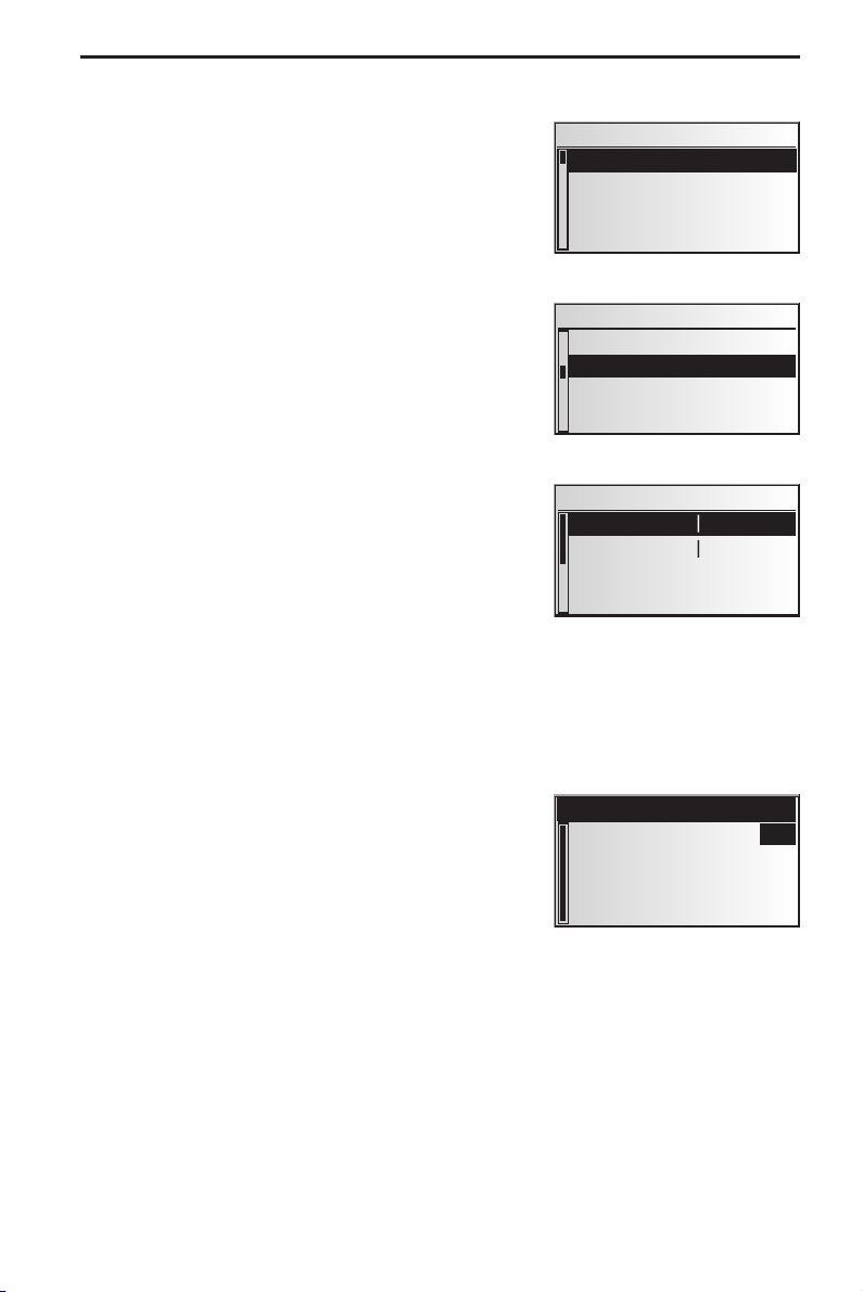
Information during guidance
During guidance, you can call up several information
screens:
Move the cursor to the ™ symbol and confirm by
☞
pressing OK.
The list of information menus appears.
☞
The following information menus are available:
Route list
This option is available as soon as a route has been
planned.
The list of segments of the planned route appears.
Confirm the required entry by pressing OK in order
☞
to view the complete road name.
Select “Return” to quit the road list.
☞
Event on the route
This information menu is only available if a TMC
extension is connected to the navigation system and
if one or more traffic obstructions are reported on
your route.
A list of segments for which traffic obstructions have
been reported appears. The list is sorted on the basis
of the location of each obstruction on the route.
Select a report in order to access detailed
☞
information about the traffic obstruction.
GUIDANCE
Travel data
Route list
Event on the route
Destination
Via points 2
Route list
B277 0.5km
B49 0.3km
Ab Anschl 0.7km
A45 18.8km
Event on the route
A67 -> 109km
B43A -> 126km
More detailed information about this function can be
found in the “Traffic info” chapter on page 41.
Car position
Display of current vehicle location with country code,
city, road, and, if available, house number.
If you are located beyond a digitised road, the screen
will display the GPS position (geographic longitude
and latitude).
The GPS position can be accessed at any time via
✎
the “Emergency” option in the main control.
Return
GB
OAKRIDGE
PARK AVENUE
39
Page 45
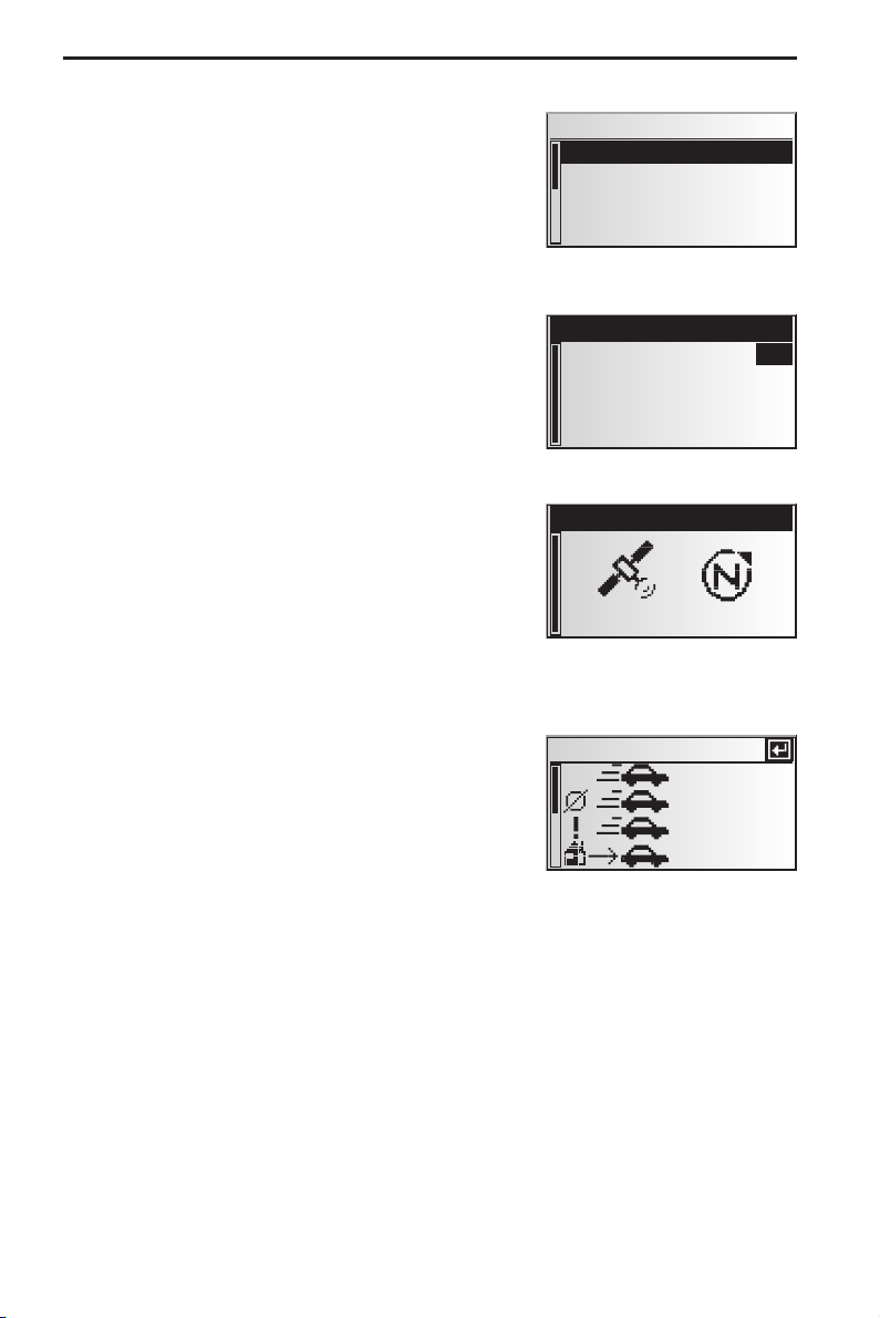
GUIDANCE
Displaying/deleting via points
If via points have been entered for the current
destination, the “Via points” option will be active.
The number of via points still to be reached also
appears.
Select the required via point from the list in order
☞
to view details or delete it.
Destination
Display of current destination address with Name
(if entered), country code, city, road, and crossroads.
GPS / Compass
Display of the following information:
1. GPS reception status: Displays the number of GPS
satellites received. With an unobstructed view of
the sky, up to 8 satellites may be displayed.
2. Current driving direction (compass). The arrow
always points north.
3. Date and time
Via points
WETZLAR >
DARMSTADT >
Return
SIEMENS VDO
D
WETZLAR
PHILIPSSTRASSE
House number: 1
Return
7
15.03.2003 8:12
Trip computer
The following information appears in the “Trip
computer” information menu:
–
Current speed
–
Average speed
–
Maximum speed so far
–
Distance travelled
–
Time travelled
■
Resetting values:
Confirm O by pressing OK.
☞
Confirm the deletion with “Yes”.
☞
All trip computer values are reset to zero.
☞
■
Speed warning:
You can enter a speed above which an alarm will sound. To set the speed limit, see
“Speed” on page 49.
40
Trip computer
55 km/h
36 km/h
167 km/h
435 km
Page 46

TRAFFIC INFORMATION*
Traffic information
Use the “Traffic info” option in the main control to
obtain information about traffic conditions in three
different categories:
At the car position
–
At the destination
–
On the route
–
Please note that the RDS-TMC station picked up by the TMC receiver may not
✎
provide any traffic information relating to your destination if the destination is
located outside the station range.
C-IQ Traffic info contents must be activated to ensure this function.
✎
At position
■
All traffic obstructions in the vicinity of the current position of your car transmitted by
the RDS-TMC station are displayed here.
At destination
■
All traffic obstructions in the vicinity of the selected destination transmitted by the
RDS-TMC station are displayed here.
■ On the route
All traffic obstructions on the route are displayed.
If no traffic information is received or there are no traffic obstructions on the route,
✎
the corresponding menu items will be greyed out.
Traffic info
At position
At destination
On the route
Viewing details relating to traffic information
Select the required traffic report from one of the three lists (“At position”, “At
☞
destination”, “On the route”) in order to view details relating to traffic
information.
The first details screen appears:
:
The following information is available:
–
Road affected
–
Distance to the start of the segment in which the
traffic obstruction is located;
–
Length of the section in which the traffic
obstruction is located;
–
Type of obstruction (e.g. road works, stationary
traffic, closed road).
As soon as you enter the segment affected by the traffic obstruction, the distance-to-go
information will disappear.
* only with TMC extension connected
On the route
A6
R
Roadworks
60 km
8.6 km
41
Page 47

TRAFFIC INFORMATION
You can use cursor key 2 to access further screens
☞
containing details about the selected traffic
obstruction.
The second details screen indicates the section in
:
which the traffic obstruction is located and the
third, the information about the obstruction
provided by the TMC provider.
A6
Mannheim ->
Heilbronn
Viernheimer Kreuz
Mannheim
TMC Provider
2 km queuing
traffic
Press OK to return to the list of traffic
☞
obstructions.
Searching / selecting TMC stations
Select “TMC Provider” from the “Traffic info” menu.
☞
Select the L icon.
☞
The list of available TMC stations is displayed.
:
Select the desired station from the list.
☞
Select “Automatic” if you want the receiver to automatically tune to the strongest
☞
station for evaluation of the TMC data.
Each time after switching off the ignition “Automatic” is set automatically.
✎
42
Page 48
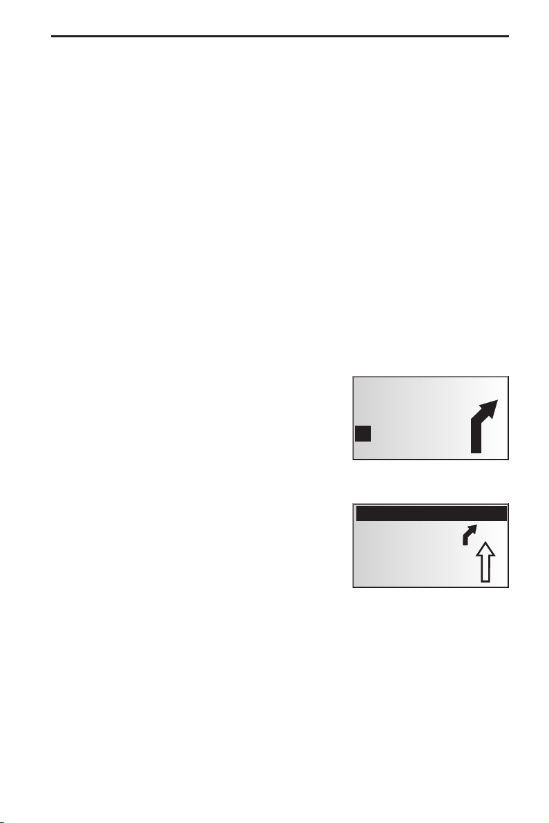
DYNAMIC GUIDANCE WITH TMC*
With RDS TMC (Traffic Message Channel), the current traffic situation is taken into
account when planning the route to your destination. You will be informed, for
example, of accidents, congestion or construction sites as soon as such a traffic
situation occurs.
If you approach the traffic obstruction, the automatic detour option is activated and
the navigation system will plan, if required, an alternative route.
TMC has not yet been introduced in all countries and is not supported by all RDS
✎
stations.
In order to be able to use dynamic guidance with TMC, you must have actiated C-IQ
✎
contents with Traffic info.
How TMC traffic announcements are made
If TMC messages are available for your planned route, they will also be announced as
voice messages.
Repeat announcement
Press the { key.
☞
You will hear the current destination guidance message and the most recent TMC
:
message.
TMC traffic information on the guidance screen
If a traffic obstruction occurs ahead of you on the
planned route, you will see information about the
obstruction on the top line of the guidance screen.
Information appears regarding the type of traffic
obstruction and the distance to the start of the
segment in which it is located. Details about the
traffic obstruction can be accessed via the “Event
on the route” information menu. See page 39.
†43km Stationary
30 m
86 km
ª
Z
21:48
IU
As you approach the traffic obstruction, the detour
option is activated. You will hear an audible signal
and the cursor will jump automatically to the top
line of the guidance screen.
The display of the traffic obstruction in the top
✎
line of the screen can be deactivated.
See page 49.
* only with TMC extension connected
†5,7km Stationary
3400 m
23 km
ª
Z
21:57
IU
43
Page 49

DYNAMIC GUIDANCE WITH TMC
Bypassing a traffic obstruction locally
When you approach the last exit before reaching a traffic obstruction, the navigation
system will alert you and offer you the option of planning a detour route.
As soon as a traffic obstruction is detected on your route and the detour option is
displayed on the guidance screen:
Confirm the detour option in the top line of the guidance screen.
☞
The detour menu is displayed.
:
Confirm “Plan a detour?” with “Yes,” if you wish to bypass the traffic obstruction.
☞
Select “No,” if you do not wish to plan a detour.
☞
If you answer “Yes”, the navigation system will
:
plan a new route in a matter of seconds. A details
screen will soon appear (diversion, time delay/
saving).
Confirm the planned detour with “Yes” or reject it
☞
with “No”.
If you reject the planned detour, the direct route
:
(which might go through the traffic obstruction)
will be planned.
Alternative route
Distance: +9.0 km
Time: +13 min
Accept alteration?
Yes No
Dynamic route planning
Unlike dynamic guidance, which provides information about traffic conditions on your
route and on request about local traffic conditions, dynamic route planning takes into
account the whole of the current traffic situation in a configurable area (horizon) in
the vicinity of the current position of the car. If a traffic obstruction (e.g. stationary
traffic) is reported via TMC for the planned route, the navigation system will analyse
the information and calculate the anticipated delay.
If there is a traffic problem on the planned route, you will be informed of this by the
navigation system and may decide whether the system should take a detour by
changing the route in order to avoid the segment concerned or whether it would be
more sensible just to drive through the problem. You should base your decision on the
anticipated delay calculated by the system.
The delay is calculated by the navigation system on the basis of the data
✎
transmitted by the TMC station, which may not actually reflect the current
situation.
Dynamic route planning can be activated in the “Route selection” menu. See page 38.
In addition, you may select criteria on which dynamic route planning should be based
in the “Settings – Dyn. route sett.” menu. See page 50.
44
Page 50

ALTERNATIVE ROUTE
During guidance, you can cause the navigation system to plan an alternative route.
Use this function if, for example, you want to avoid stationary traffic not reported via
TMC or if you wish to plan an alternative route.
The alternative route will be calculated for a selectable distance from the current
position of the car.
Press the ALT-R key on the remote control,
☞
or:
move the cursor to the ª symbol in the guidance
☞
screen and confirm by pressing OK.
If you agree with the displayed distance, confirm
☞
with “OK”.
The system is planning an alternative route for the
:
entered distance. A details screen will soon appear
(diversion, time delay/saving).
Confirm the planned alternative route with “Yes”
☞
or reject it with “No”.
If you reject the alternative route, the navigation
✎
system will plan a new route to the destination
from the current position of the car.
The display shows the guidance screen again.
:
Cancel procedure
Move the cursor to “Quit” and press OK.
☞
Alternative route
10 km
OK Quit
Alternative route
Distance: +9.0 km
Time: +13 min
Accept alteration?
Yes No
Change distance
If you wish to change the distance displayed, proceed as follows:
Move the cursor to the displayed distance.
☞
Press OK.
☞
Change the displayed distance in the range of 1 to 10 km using cursor keys 4 or 6.
☞
Press OK again.
☞
The cursor is set on “OK”.
:
Confirm with “OK”.
☞
The system will suggest an alternative route for the planned trip as described
✎
above.
45
Page 51

ADDRESS MANAGER
Address Manager
The VDO Dayton Navigation System allows you to store 30 destination addresses in a
personal address book. In the address book, you can store your destinations separately
under the categories “Private” and “Business”. The “Home” and “Work” shortcuts,
which can be programmed with your home address and business address respectively,
are also available here.
Select the “Address manager” in the main control
☞
and confirm the selection.
The address manager is displayed.
:
The following options are available:
Storing addresses in the address book.
If you have not yet entered a destination address:
Enter the data of the required destination address (city, road, crossroads or special
☞
facility) into the destination menu.
In the main control, select the “Address manager” option.
☞
Next, select “Store address”.
☞
Select which address books the address should be stored in (private, business, home
☞
or work).
The name input menu appears (only for “Private” and for “Business”).
:
Using the “typewriter,” enter any string of up to 15 characters as the name for the
☞
address. Complete the input with “o”.
If you do not wish to enter a name, select “o” directly.
✎
The address is now stored in the selected address book.
:
Delete address
Addresses that are no longer needed should be deleted from the address book to
ensure sufficient space for new addresses.
Select “Delete address” in the address manager.
☞
Select which address book the address should be deleted from (private, business,
☞
home or work).
A list of the destination addresses stored in the selected address book is displayed.
:
Select an address to be deleted from the list and confirm your selection.
☞
The selected address is deleted from the address book.
:
Delete via points
If via points have been entered for the current destination, you can display the via point
list and delete via points from it.
Select “Delete via points” in the address manager.
☞
A list of the stored via points appears.
:
Select a via point to be deleted from the list and confirm your selection.
☞
The selected via point is deleted.
:
Via points can also be deleted in the “Via points” information menu, see page 40.
✎
Address manager
Store address
Delete address
Delete via points
Store current loc.
46
Page 52

ADDRESS MANAGER
Store current loc.
Would you like to store a favourite restaurant in the destination memory? You can store
the current position of your car as follows:
Select “Store current loc.” in the address manager.
☞
Select which address books the address should be stored in (private, business, home
☞
or work).
The name input menu appears (only for “Private” and for “Business”).
:
Enter a name and complete the input with o.
☞
If you do not wish to enter a name, select “o” directly.
✎
The current position of the car is stored as an address in the selected address book.
:
Deleting list of last destinations
Select “Delete last dest.” in the address manager.
☞
The list of destinations last used for guidance is displayed.
:
Renaming addresses
If you wish to change the name of a destination address, select the “Rename address”
option in the address manager.
Select which address book the address should be edited in (private, business, home
☞
or work).
Select the address to be edited from the list and enter a new name for it.
☞
Confirm your entry with “o”.
☞
The address will be stored under the new name in the address book.
✎
Comments:
30 entries is the guaranteed minimum of entries for the address book. This total can
be up to 200, depending on the data entered (e.g. with or without a name, etc.)
If there is no address in the address book, the “Delete address” option cannot be
selected.
If no via points have been entered for the current destination, the “Delete via
points” option cannot be selected.
Once the address book is full, the “Store address” and “Store current loc.”
options will no longer be available.
47
Page 53

EMERGENCY
Emergency menu
Select “Emergency” from the main control menu.
☞
The “Emergency” menu is shown.
:
The following options are available in the
“Emergency” menu:
GPS position
Shows the current geographical position of the vehicle evaluated by the Global
Positioning System. The degrees of longitude and latitude as well as the height above
sea level (sufficient GPS reception must be provided).
Car position
Shows the current vehicle position with country code, city and road. This option is only
available if you are located on a digitised road.
Emergency
GPS position
Car position
48
Page 54

SYSTEM SETTINGS
To customise the navigation functions to your own
needs, you can change several settings.
In the main control, select “System settings”.
☞
The “System settings” menu is displayed.
:
The following options are available:
System settings
Speed
Guidance screen
Dyn. route sett.
Language
Speed
In the “Speed” menu, you can configure the following settings:
Speed correction
The navigation system uses an average cruising speed to calculate the remaining travel
time and the estimated time of arrival. If required, you can adapt this speed to your
actual average speed.
However, we do not recommend you deviate significantly from the standard value
of 100%.
Move the cursor to the value after “Correction”.
☞
Press OK.
☞
Set the required speed correction using cursor keys 4 or 6.
☞
To save the setting press OK again.
☞
Speed limit
Use this value to specify the vehicle speed at which a speed warning should be output.
Move the cursor to the value after “Limit (km/h):”.
☞
Press OK.
☞
Set the required speed using cursor keys 4 or 6.
☞
To save the setting press OK again.
☞
Activating/deactivating speed warning:
Move the cursor to the option after “Limit:”.
☞
Press OK to choose between “On” and “Off”.
☞
If the speed warning is activated, a warning sound is triggered each time the set
✎
speed limit is exceeded and a warning appears on the screen.
SDVC Mode (Speed dependent volume control)
This is to compensate the surrounding noise by increasing the volume level of
guidance advice depending on the car’s speed.
You can select between 5 different SDVC settings (OFF = off; 4 = maximum increase).
Move the cursor to the value after “SDVC mode”.
☞
Press OK.
☞
Set the desired SDVC mode using the cursor keys 4 or 6.
☞
To save the setting press OK again.
☞
Find a suitable compensation by trying out the different modes.
49
Page 55

SYSTEM SETTINGS
Guidance screen
Here you can select the information which should appear on the guidance screen.
Show event
■
Select whether traffic obstructions on your route should appear in the top line of
☞
the guidance screen or not.
Remain. distance
■
Select whether the distance-to-go to the destination or via point should appear in
☞
the status field of the guidance screen or not.
Times
■
Select which times should appear in the status field of the guidance screen. The
☞
following options are available:
Time of arrival
–
Remaining time
–
Current time
–
No time display
–
Dyn. route sett.
Settings for dynamic route planning
■ Re-route lev.
Use this setting to specify whether the navigation system should plan a detour in the
event of traffic obstructions or not. Five levels are available. The lowest level (1) means
that the direct route should go through the stationary traffic depending on the
conditions and the anticipated delay. If the highest level is selected, an alternative
route should be planned in most cases.
Level 3 is a standard setting for dynamic route planning. It is the factory setting
✎
(default).
■
Horizon
This setting determines the radius in which the navigation system should take traffic
obstructions into account when planning your route. Select a value between 25 and
150 km.
■
Delay
Use this value to indicate the anticipated delay time due to a traffic obstruction at or
above which the navigation system should suggest that a new route be planned.
Select a value between 5 and 60 minutes.
The anticipated delay is calculated on the basis of the data received from the TMC
✎
station and may deviate from the actual situation.
50
Page 56

SYSTEM SETTINGS
Language
Choose one of the two languages loaded in the system,
☞
or:
Select “Other language” to replace one of the two loaded languages with another
☞
language from the supplied “VDO Dayton Language Loading Software CD”.
Select the language to be replaced.
☞
You will be prompted to insert the CD.
:
Insert the CD in the navigation computer.
☞
Follow the system instructions for loading other languages.
☞
Turn now advice
■
If this option is activated, an additional prompt (e.g. “Now turn right”) will be output
directly before a turn-off.
This prompt is activated by default.
✎
Volume
Adjusting the volume:
Place the cursor on the volume slider.
☞
Confirm by pressing OK.
☞
The volume adjustment is activated now.
:
Adjust the desired volume level with the cursor keys 4 or 6.
☞
The selected volume setting is announced.
:
Press OK again to store the setting.
☞
Voice messages on/off:
Place the cursor on the option behind the loudspeaker icon.
☞
Press OK.
☞
Select Mode “On” or “Off”.
☞
Press OK again to store this selection.
☞
Date / Clock
You can set the format for time and date display as well as the time zone.
Time zone:
The navigation system receives the Universal Time Coordinated (UTC) via the GPS
system.
To adjust the difference between your local time and UTC:
Place the cursor on the value behind “Timezone:”.
☞
Press OK.
☞
Adjust the time offset with cursor keys 4 and 6.
☞
Press OK again to store the setting.
☞
The displayed time is updated.
:
k
51
Page 57

SYSTEM SETTINGS
Time format:
Select between 12 hour format and 24 hour format.
☞
Date format:
Select between “day.month.year” and “month/day/year” format.
☞
Display
For overhead mounting of the display it is possible to rotate the display contents
180 degrees.
Select the desired setting according to the mounting position of the display.
☞
Remote control
Steering wheel
■
Activate this option if you want to control the system with a VDO Dayton steering
wheel remote control (accessory).
Favourite button
■
You can assign a function to the FAVOURITE key on the remote control.
Select one of the displayed functions to assign it to the short or long press of the
☞
FAVOURITE key.
Measuring units
Select between the following measuring units:
☞
–
Metric: display in kilometres and metres;
–
Anglo: display in miles and yards;
–
American: display in miles, half and quarter miles and feet.
Mounting angle
To adapt the navigation computer to the mounting angle at the installation position
(gyro-sensor compensation). This adjustment only needs to be made once, immediately
after the installation of the navigation system. See “Setting the mounting angle”,
page 14.
Default settings
Select this option if you want to reset all user specific settings and values to their
factory defaults. All address book entries remain stored.
Service
For analysing hardware and software problems (code protected).
The “Service” menu should only be entered for service of the Navigation System by
an authorized service centre.
System information
The “System information” menu shows you information on soft- and hardware
versions of the system (for service purposes).
52
Page 58

MAP CDs
Notes on map CDs
The navigation system is based on a C-IQ database, which is stored on a CD in
encrypted format. The CD contains map data for navigation as well as travel and
traffic information (TMC) for dynamic route planning. You can customise your
navigation package by activating specific components of the database.
For further information see “C-IQ - INTELLIGENT CONTENT ON DEMAND”, see page 20.
Changing the map CD
If the ignition is switched on and the red power LED lights up permanently:
Press the W key on the navigation computer.
☞
The CD is ejected.
✎
If the ignition is switched off and if the power LED flashes:
Press the W key.
☞
Wait for at least 10 seconds until the LED stops flashing.
☞
Press the W key again.
☞
The CD is ejected.
✎
Take out the CD and gently insert the new map CD with the printed side facing up
☞
until it is retracted.
The system needs a few seconds for initialisation after changing the map CD.
✎
Notes:
Only use genuine VDO Dayton C-IQ map CDs. These map CDs are exclusively designed
for use with the VDO Dayton Navigation System and they are only readable by a VDO
Dayton Navigation System.
The CD player of the navigation system does not play any other CDs (i.e. Audio CDs).
Always store map CDs in their protective cases.
Always make sure that the CD you insert is clean and dry.
If the last entered destination address is not (or only partly) on the map CD you
inserted, the whole address (or only the not existing part) is deleted.
r
e
d
e
i
n
h
c
s
n
e
t
h
c
ü
F
n
o
g
E
d
n
lf
a
o
R
B
d
n
a
53
Page 59

MAINTENANCE & CARE
Replacing batteries of the remote control
You have to replace the batteries of the remote control, if you use the remote control
outside of its holder and the navigation system does no longer respond to key presses.
Open the battery compartment on the back of the
☞
remote control.
Remove the discharged batteries.
☞
Insert two new LR03 type (Size AAA) batteries. Pay
☞
attention to correct polarity (marked in the
compartment).
Close the battery compartment.
☞
Notes:
In many countries exhausted batteries may not be disposed of with your household
waste. Please determine how to dispose of exhausted batteries according to local
regulations.
Only use leak-proof batteries. Battery leakage can cause damage to the remote
control or to your car.
Never expose the remote control to direct sunlight or extreme heat. The batteries are
discharged and the risk of leakage is increased.
If you permanently use your remote control in the active holder RCD 3200 (accessory),
we recommend that you remove the batteries from the remote control.
Cleaning of the remote control and the monitor
Do not use lighter fluid, methyl alcohol or other solvents for cleaning. Only use a
damp cloth.
Loading software updates
In order to extend the range of functions, you can load software updates from a
system software CD, provided that these are available for your system:
Switch on the ignition and confirm the safety notification.
☞
Remove the map CD from the navigation computer and insert the software update
☞
CD.
A security check appears. Confirm the inquiry with “Yes” if you wish to overwrite
☞
the software which is loaded on the system.
The new operating software is now loaded automatically. Loading progress is
:
indicated by a bar.
A
On no account must the ignition be switched off during the loading procedure, even if
no displays appear on the monitor for a while.
After successful loading, you will be prompted to remove the software update CD
:
and to re-insert the map CD.
Please confirm the completion of the loading procedure with “OK”.
☞
The system is subsequently re-started with the new operating software.
:
54
Page 60

TROUBLESHOOTING
There may be times when you suspect that your navigation system is not functioning
as you expect it to. Before calling for service please read the operating instructions
and check the following list. You may find that an apparent malfunction can easily be
rectified.
Symptoms Possible cause / Remedy
System does not start. Nothing on
the display.
After some time of normal
operation, the system switches off.
System does not react on key
presses when the remote control is
not in its holder.
System reacts very slowly to data
entries or calculates very slowly.
The number of satellites in the
“GPS/Compass” information menu
is 0.
Guidance advice not audible. • Make sure that the volume is not set to minimum.
Display shows “Please insert CD” or
“Please insert correct CD”
Map CD is ejected unintentionally
without pressing the W key.
Not possible to store address in the
address book.
Guidance is not precise. Inaccuracy of a max. of 30 m is possible.
Displayed car position does not
match actual car position.
• Switch on the ignition.
Ignition is already switched on:
System is in stand-by mode.
• Press one of the keys on the remote control.
Monitor connector is not locked correctly.
• Slide the monitor onto the support (connector) until it clicks into
position correctly.
At extreme high or low temperatures the built-in protection circuit
switches off the system automatically.
• Operation of the system is resumed as soon as the temperature
returns to a normal level.
Batteries are empty.
• Replace the batteries.
With active Holder RCD 3200:
• Put the remote control into the holder.
You are in a very densely digitized area. The navigation system has
to read a large amount of data from the CD-ROM.
• Make sure the GPS aerial is not covered by any objects.
• Drive outdoors, if you are in a garage, a car park or a tunnel.
• Make sure that the voice messages are activated in the “System
settings – Volume” menu (“¦: On” ).
• Make sure that an appropriate CD is inserted with the printed
side facing up in the navigation computer.
The CD might be dirty.
• Try to clean the CD with a special CD cleaning fluid.
Address book is full.
• Delete one or more entries no longer required.
• If you frequently discover greater inaccuracy, contact an
authorized service centre.
The navigation system indicates the distance to the next turn as the
distance to the centre of the junction (especially for extensive
junctions or crossroads).
Bad GPS reception for a longer period of time (for example caused
by interference). When sufficient GPS reception is resumed the
position is corrected automatically.
• If necessary wait a few minutes.
55
Page 61

TROUBLESHOOTING
Symptoms Possible cause / Remedy
Guidance advice does not
correspond with actual traffic
situation.
The time in the “GPS/Compass”
information menu is incorrect.
Estimated time of arrival is wrong in
the guidance screen.
TMC icon in the “Traffic info” menu
is always coarsely shaded, no traffic
info is displayed.
TMC icon in the “Traffic info” menu
is finely shaded.
C-IQ
During guidance, no traffic
information is displayed, even
though a TMC extension is
connected to the system.
No more directions shortly after
crossing the border. Only the
direction arrow is appearing in the
guidance screen.
Display shows “Please insert correct
CD”.
It is possible that the car position calculated by the navigation
system is currently wrong.
The route may have been changed and does not correspond with
the information stored on the map CD.
Set the correct time zone in the “System settings – Date / Time”
menu.
Check that the correct time zone in the “System settings – Date /
Time” menu is set.
The inserted map CD does not support TMC.
Insert a map CD which supports TMC.
TMC reception is interfered / obstructed or you are located in an
area in which no RDS station broadcasts TMC information.
You do not have a C-IQ Traffic info product activated.
• Contact C-IQ service to activate C-IQ Traffic info contents.
You are travelling in a country for which you do not have activated
C-IQ map contents.
• Contact C-IQ Service to activate map data for the required
country.
• Check that you have inserted a map CD which contains C-IQ
data. Map CDs without C-IQ will not be accepted by the system.
Hotlines are available in many countries to handle queries about the VDO Dayton
multimedia systems. Up-to-date telephone numbers can be found in the accompanying
info sheet.
VDO Dayton on the Internet: www.vdodayton.com
Subject to technical modifications and errors.
56
 Loading...