


 Loading...
Toshiba RAS-13YKH-ES, RAS-07YKHE, RAS-07YAH-ES, RAS-07YAH-E, RAS-10YKH-E SERVICE MANUAL
...FILE NO. DAS-SM-00-003
SUPPLEMENT
SERVICE MANUAL
AIR-CONDITIONER
SPLIT WALL TYPE
RAS-07YKH-E/RAS-07YAH-E RAS-10YKH-E / RAS-10YAH-E RAS-13YKH-E / RAS-13YAH-E RAS-07YKH-ES/RAS-07YAH-ES RAS-10YKH-ES / RAS-10YAH-ES RAS-13YKH-ES / RAS-13YAH-ES
|
CONTENTS |
|
1. |
SPECIFICATIONS .................................................................................... |
3 |
2. |
CONSTRUCTION VIEWS ....................................................................... |
7 |
3. |
WIRING DIAGRAM ................................................................................ |
10 |
4. |
SPECIFICATIONS OF ELECTRICAL PARTS ..................................... |
12 |
5. |
REFRIGERANT CYCLE DIAGRAM ..................................................... |
15 |
6. |
CONTROL BLOCK DIAGRAM ............................................................. |
21 |
7. |
OPERATION DESCRIPTIONS................................................................ |
22 |
8. |
INSTALLATION PROCEDURE .............................................................. |
30 |
9. |
TROUBLESHOOTING CHART .............................................................. |
44 |
10. |
PART REPLACEMENT .......................................................................... |
60 |
11. |
EXPLODED VIEWS AND PARTS LIST .............................................. |
65 |
– 2 –
1. SPECIFICATIONS
RAS-10YKH-E / RAS-10YAH-E, RAS-13YKH-E / RAS-13YAH-E
|
|
|
|
MODEL |
RAS-10YKH-E/10YAH-E |
|
RAS-13YKH-E/13YAH-E |
|||||
ITEM |
|
|
|
|
|
Cooling |
|
Heating |
|
Cooling |
|
Heating |
Capacity |
|
|
|
|
kW *1 |
220V–240V |
|
220V–240V |
|
220V–240V |
|
220V–240V |
|
|
|
|
2,65–2,70 |
|
3,00–3,10 |
|
3,45–3,50 |
|
4,00–4,10 |
||
|
|
|
|
|
Phase |
|
|
Single |
|
|||
Power source |
|
|
|
|
V |
|
|
220–240 |
|
|||
|
|
|
|
|
Hz |
|
50 |
|
|
|||
Power consumption |
|
|
|
|
kW |
0,98–1,02 |
|
0,89–0,91 |
|
1,26–1,30 |
|
1,19–1,27 |
Power factor |
|
|
|
% |
95–90 |
|
95–88 |
|
98–92 |
|
95–93 |
|
Running current |
|
|
|
|
V |
220V–240V |
|
220V–240V |
|
220V–240V |
|
220V–240V |
|
|
|
|
|
|
|
|
|
|
|
|
|
Indoor/Outdoor |
|
|
|
A |
0,11/4,58 - 0,11/4,61 |
0,11/4,17 - 0,11/4,22 |
|
0,15/5,70 - 0,15/5,75 |
0,15/5,54 - 0,15/5,44 |
|||
|
|
|
|
|
||||||||
Starting current |
|
|
|
|
A |
19 |
|
14 |
|
25 |
|
25 |
Moisture removal |
|
|
|
|
lit/h |
|
1,2 |
|
2,0 |
|
||
|
|
|
|
|
|
|
|
|
|
|
|
|
Noise |
Indoor (H/M/L) |
|
|
|
dB (A) |
41 / 36 / 29 |
|
41 / 36 / 29 |
|
44 / 39 / 34 |
|
44 / 39 / 34 |
(SPL at 1 meter) |
Outdoor (220–240V) |
|
dB (A) |
47–49 |
|
47–49 |
|
49 / 51 |
|
49 / 51 |
||
Refrigerant |
Name of refrigerant |
|
|
|
|
R-22 |
|
|||||
|
|
|
|
|
|
|
|
|
|
|
|
|
Rated volume |
|
|
|
kg |
|
0,74 |
|
0,88 |
|
|||
|
|
|
|
|
|
|
||||||
Refrigerant control |
|
|
|
|
|
|
|
Capillary tube |
|
|||
|
Gas side size |
|
|
|
mm |
|
9,52 |
|
12,7 |
|
||
|
Connection type |
|
|
|
|
|
|
Flare connection |
|
|||
|
Liquid side size |
|
|
|
mm |
|
6,35 |
|
|
|||
Interconnection pipe |
Connection type |
|
|
|
|
|
|
Flare connection |
|
|||
|
|
|
|
|
|
|
|
|
|
|
|
|
Maximum length (of one way) |
|
m *2 |
|
10 |
|
15 |
|
|||||
|
|
|
|
|
||||||||
|
Maximum height difference |
|
|
|
|
|
|
|
|
|
||
|
Indoor unit |
|
|
|
|
|
5 |
|
6 |
|
||
|
↑ |
|
m |
|
|
|
||||||
|
Outdoor unit |
↓ |
|
|
|
|
|
|
|
|
||
|
|
|
|
|
|
|
|
|
|
|||
Condensate drain pipe |
Outer diameter |
|
|
|
mm |
|
16 |
|
|
|||
INDOOR UNIT |
|
|
|
|
|
RAS-10YKH-E |
|
RAS-13YKH-E |
||||
|
Height |
|
|
|
mm |
|
265 |
|
|
|||
Dimensions |
Width |
|
|
|
mm |
|
790 |
|
|
|||
|
|
|
|
|
|
|
|
|
|
|
||
|
Depth |
|
|
|
mm |
|
189 |
|
|
|||
Net weight |
|
|
|
|
kg |
|
|
|
8 |
|
|
|
Evaporator type |
|
|
|
|
|
|
|
Finned tube |
|
|||
|
|
|
|
|
|
|
|
|
|
|||
Indoor fan type |
|
|
|
|
|
|
|
Cross flow fan |
|
|||
|
High fan |
|
|
|
m³/h |
|
600 |
|
650 |
|
||
Air flow rate |
Medium fan |
|
|
|
m³/h |
|
500 |
|
560 |
|
||
|
Low fan |
|
|
|
m³/h |
|
400 |
|
510 |
|
||
Fan motor output |
|
|
|
|
W |
|
20 |
|
|
|||
Air filter |
|
|
|
|
|
|
|
Polypropylene net filter (Washable) |
|
|||
|
|
|
|
|
|
|
|
|
|
|||
OUTDOOR UNIT |
|
|
|
|
|
RAS-10YAH-E |
|
RAS-13YAH-E |
||||
|
Height |
|
|
|
mm |
|
530 |
|
538 |
|
||
|
|
|
|
|
|
|
|
|
|
|
|
|
Dimensions |
Width |
|
|
|
mm |
|
770 |
|
780 |
|
||
|
Depth |
|
|
|
mm |
|
200 |
|
300 |
|
||
|
|
|
|
|
|
|
|
|
|
|
|
|
Net weight |
|
|
|
|
kg |
|
31 |
|
42 |
|
||
Condenser type |
|
|
|
|
|
|
|
Finned tube |
|
|||
Outdoor fan type |
|
|
|
|
|
|
|
Propeller |
|
|||
|
|
|
|
|
|
|
|
|
|
|||
Air flow rate (220–240V) |
|
|
|
|
m³/h |
1500–1700 |
|
1690–1730 |
||||
Fan motor output |
|
|
|
|
W |
|
18 |
|
28 |
|
||
Compressor |
Model |
|
|
|
|
PH120T1-4C |
|
PH170T2-4L2 |
||||
Output |
|
|
|
W |
|
750 |
|
1100 |
|
|||
|
|
|
|
|
|
|
||||||
Safety device |
|
|
|
|
|
|
|
Fuse, Overload relay |
|
|||
Auto louver |
|
|
|
|
|
|
|
Yes |
|
|||
Usable outdoor temperature range |
|
|
|
°C |
21–43 |
|
-5–21 |
|
21–43 |
|
-5–21 |
|
|
|
|
|
|
|
|
|
|
|
|
|
|
Specifications are subject to change without notice.
– 3 –

RAS-10YKH-ES / RAS-10YAH-ES, RAS-13YKH-ES / RAS-13YAH-ES
|
|
|
|
|
MODEL |
RAS-10YKH-ES/10YAH-ES |
|
RAS-13YKH-ES/13YAH-ES |
|||||
ITEM |
|
|
|
|
|
|
Cooling |
|
Heating |
|
Cooling |
|
Heating |
Capacity |
|
|
|
|
|
kW *1 |
|
|
220V–240V |
|
|||
|
|
|
|
|
2,65–2,70 |
|
3,00–3,10 |
|
3,45–3,50 |
|
4,00–4,10 |
||
|
|
|
|
|
|
Phase |
|
|
Single |
|
|||
Power source |
|
|
|
|
|
V |
|
|
220–240 |
|
|||
|
|
|
|
|
|
|
|
|
|
|
|||
|
|
|
|
|
|
Hz |
|
50 |
|
|
|||
Power consumption |
|
|
|
|
|
kW |
0,98–1,02 |
|
0,89–0,91 |
|
1,26–1,30 |
|
1,19–1,27 |
Power factor |
|
|
|
|
% |
95–90 |
|
95–88 |
|
98–94 |
|
97–93 |
|
Running current |
|
|
|
|
|
V |
|
|
220V–240V |
|
|||
Indoor/Outdoor |
|
|
|
|
A |
0,11/4,44 - 0,11/4,46 |
0,11/4,15 - 0,11/4,10 |
|
0,15/5,70 - 0,15/5,61 |
0,15/5,43 - 0,15/5,54 |
|||
|
|
|
|
|
|
||||||||
Starting current |
|
|
|
|
|
A |
19 |
|
14 |
|
25 |
|
25 |
Moisture removal |
|
|
|
|
|
lit/h |
|
1,2 |
|
2,0 |
|
||
Noise |
Indoor (H/M/L) |
|
|
|
|
dB (A) |
41 / 36 / 29 |
|
41 / 36 / 29 |
|
44 / 39 / 34 |
|
44 / 39 / 34 |
(SPL at 1 meter) |
Outdoor (220–240V) |
|
dB (A) |
47–49 |
|
47–49 |
|
49 / 51 |
|
49 / 51 |
|||
Refrigerant |
Name of refrigerant |
|
|
|
|
R-410A |
|
||||||
Rated volume |
|
|
|
|
kg |
|
0,69 |
|
0,80 |
|
|||
|
|
|
|
|
|
|
|
||||||
Refrigerant control |
|
|
|
|
|
|
|
|
Capillary tube |
|
|||
|
Gas side size |
|
|
|
|
mm |
|
9,52 |
|
|
|||
|
Connection type |
|
|
|
|
|
|
|
Flare connection |
|
|||
|
Liquid side size |
|
|
|
|
mm |
|
6,35 |
|
|
|||
Interconnection pipe |
Connection type |
|
|
|
|
|
|
|
Flare connection |
|
|||
Maximum length (of one way) |
|
m *2 |
|
10 |
|
15 |
|
||||||
|
|
|
|
|
|||||||||
|
Maximum height difference |
|
|
|
|
|
|
|
|
|
|||
|
Indoor unit |
|
|
|
|
|
|
5 |
|
6 |
|
||
|
↑ |
|
m |
|
|
|
|||||||
|
Outdoor unit |
↓ |
|
|
|
|
|
|
|
|
|
|
|
|
|
|
|
|
|
|
|
|
|
|
|||
|
|
|
|
|
|
|
|
|
|
|
|||
Condensate drain pipe |
Outer diameter |
|
|
|
|
mm |
|
16 |
|
|
|||
INDOOR UNIT |
|
|
|
|
|
|
RAS-10YKH-ES |
|
RAS-13YKH-ES |
||||
|
Height |
|
|
|
|
mm |
|
265 |
|
|
|||
Dimensions |
Width |
|
|
|
|
mm |
|
790 |
|
|
|||
|
Depth |
|
|
|
|
mm |
|
189 |
|
|
|||
Net weight |
|
|
|
|
|
kg |
|
|
|
8 |
|
|
|
Evaporator type |
|
|
|
|
|
|
|
|
Finned tube |
|
|||
Indoor fan type |
|
|
|
|
|
|
|
|
Cross flow fan |
|
|||
|
High fan |
|
|
|
|
m³/h |
|
600 |
|
650 |
|
||
Air flow rate |
Medium fan |
|
|
|
|
m³/h |
|
500 |
|
560 |
|
||
|
Low fan |
|
|
|
|
m³/h |
|
400 |
|
510 |
|
||
Fan motor output |
|
|
|
|
|
W |
|
20 |
|
|
|||
Air filter |
|
|
|
|
|
|
|
|
Polypropylene net filter (Washable) |
|
|||
OUTDOOR UNIT |
|
|
|
|
|
|
RAS-13YAH-E |
|
RAS-13YAH-ES |
||||
|
Height |
|
|
|
|
mm |
|
530 |
|
538 |
|
||
Dimensions |
Width |
|
|
|
|
mm |
|
770 |
|
780 |
|
||
|
Depth |
|
|
|
|
mm |
|
200 |
|
300 |
|
||
Net weight |
|
|
|
|
|
kg |
|
31 |
|
42 |
|
||
Condenser type |
|
|
|
|
|
|
|
|
Finned tube |
|
|||
Outdoor fan type |
|
|
|
|
|
|
|
|
Propeller |
|
|||
Air flow rate (220–240V) |
|
|
|
|
|
m³/h |
1500–1700 |
|
1690–1730 |
||||
Fan motor output |
|
|
|
|
|
W |
|
18 |
|
28 |
|
||
Compressor |
Model |
|
|
|
|
|
PA118X1T-4FZ |
|
PA160X2T-4FM |
||||
Output |
|
|
|
|
W |
|
750 |
|
1100 |
|
|||
|
|
|
|
|
|
|
|
||||||
Safety device |
|
|
|
|
|
|
|
|
Fuse, Overload relay |
|
|||
Auto louver |
|
|
|
|
|
|
|
|
Yes |
|
|||
Usable outdoor temperature range |
|
|
|
|
°C |
21–43 |
|
-5–21 |
|
21–43 |
|
-5–21 |
|
Specifications are subject to change without notice.
– 4 –

Note : *1
• Capacity is based on the following temperature conditions.
CONDITION |
COOLING |
HEATING |
|
TEMPERATURE |
|
|
|
(DB) |
27 °C |
20 |
°C |
Indoor unit inlet air temperature |
|
|
|
(WB) |
19 °C |
12 |
°C |
(DB) |
35 °C |
7 |
°C |
Outdoor unit inlet air temperature |
|
|
|
(WB) |
24 °C |
6 |
°C |
Notes : *2 CHARGELESS
RAS-07YKH-E, RAS-07YKH-ES, RAS-10YKH-E, RAS-10YKH-ES
•No additional refrigerant required.
•This air conditioner accepts a connection piping length of up to 10m and a head of up to 5m.
•There is no need to add the refrigerant as long as the total length of the connection piping is up to 10m.
RAS-13YKH-E, RAS-13YKH-ES
•No additional refrigerant required.
•This air conditioner accepts a connection piping length of up to 15m and a head of up to 6m.
•There is no need to add the refrigerant as long as the total length of the connection piping is up to 15m.
– 6 –
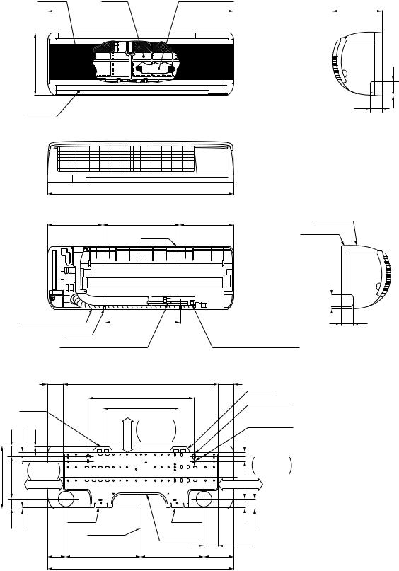
2. CONSTRUCTION VIEWS
2-1. Indoor Unit
Air inlet |
|
|
|
|
|
|
|
Air filter |
|
|
|
Heat exchanger |
|||||||||||||||||||||||||||
|
|
|
|
|
790 |
189 |
|||||||||||||||||||||||||||||||||
|
|
|
|
|
|
|
|
|
|
|
|
|
|
|
|
|
|
|
|
|
|
|
|
|
|
|
|
|
|
|
|
|
|
|
|
|
|
|
|
|
|
|
|
|
|
|
|
|
|
|
|
|
|
|
|
|
|
|
|
|
|
|
|
|
|
|
|
|
|
|
|
|
|
|
|
|
|
|
|
265 50
47 |
10 |
|
Air outlet
Knock out system
790
232 |
326 |
Front panel |
232 |
||
|
Hanger |
Back body |
|
|
50
Drain hose (0,54m) |
321 |
|
Hanger |
|
|
Connecting pipe (0,39m) |
Connecting pipe (0,49m) |
|
(Flare Ø9,52) |
|
(Flare Ø6,35) |
(Flare Ø12,7 for 13YKH-E only) |
|
|
|
|
|
65,5 |
|
659 |
65,5 |
Hanger |
|
|
|
|
|
450 |
|
|
|
|
|
|
|
|
For stud bolt |
|
|
|
Hanger |
|
326 |
|
||
|
|
|
|
(Ø8~Ø10) |
|||
|
|
|
|
|
66 or more |
|
|
|
|
|
|
|
|
|
|
|
|
|
|
|
Minimum |
|
For stud bolt |
|
46 |
20 |
2,5 |
|
distance |
20 |
(Ø6) |
|
|
to ceiling |
|
||||
|
|
|
|
|
|
|
|
|
|
|
|
|
|
|
Minimum |
265 |
178,5 |
17 |
Minimum |
|
|
|
distance |
120 or more |
|
|
120 or more |
||||
|
|
|
distance |
|
|
20 |
to wall |
|
|
|
to wall |
|
|
|
|
|
40,5 |
3,5 |
|
|
|
37 |
40,5 |
|
|
Hanger |
Hanger |
|
|||
|
|
|
|
|
|
||
|
|
|
|
Center line |
Installation |
|
|
|
|
|
|
plate outline |
|
|
|
|
|
|
|
|
60,5 |
||
|
|
|
|
|
|
||
|
|
|
76 |
319 |
269 |
126 |
|
|
|
|
|
|
790 |
|
|
10 |
47 |
Knock out system
– 7 –
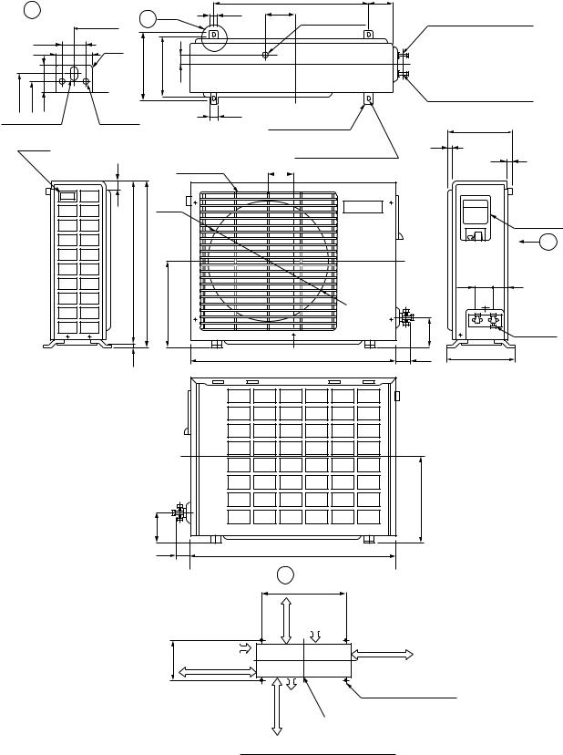
2-2. Outdoor Unit
RAS-07YKH-E, RAS-07YKH-ES, RAS-10YKH-E, RAS-10YKH-ES
|
A Detail Drawing |
A |
36 |
||
|
|
|
600 |
|
|
|
|
36 |
R10 |
|
|
|
|
50 |
|
|
|
|
|
|
230 |
216 |
30 |
230 |
216 |
25 |
|
|
50 |
Ø11x14 Hole |
Ø6 Hole |
|
|||
|
|
||||
|
Handle |
|
|
|
|
|
|
|
11 |
|
Fan guard |
|
|
|
|
|
|
|
|
|
|
Ø420 |
|
525 |
530 |
268
5
600 |
85 |
111
Ø25 Drain hole |
|
Gas side (flare Ø9,52) |
|
|
|
|
|
|
|
Liquid side (flare Ø6,35) |
|
8-Ø6 Holes |
200 |
|
(For fixing the outdoor unit) |
12 |
|
4-Ø11x14 Long holes |
||
11 |
||
111 (For anchor bolt Ø8-Ø10) |
||
|
||
TOSHIBA |
Electric |
|
|
parts cover |
Z
|
54 |
62 |
|
|
Service |
|
89 |
port |
770 |
59 |
250 |
89
230
268
59 |
770 |
|
|
Z View |
|
or more |
600 |
|
Inlet port |
|
|
45 |
|
600 or more |
Inlet port |
|
|
|
|
|
100 or more |
Visible outline |
(Minimum distance |
|
of the product |
of the wall) |
more |
Outlet |
4-Ø11x14 Long holes |
|
(For anchor bolt Ø8-Ø10) |
|||
port |
|||
or |
|
Center |
|
400 |
|
||
|
port |
Mounting dimension of anchor bolt
– 8 –

RAS-13YAH-E, RAS-13YAH-ES
A Detail Drawing
|
|
600 |
|
50 |
R10 |
|
36 |
|
|
|
|
325 301 |
|
23 |
|
Ø6 hole |
Ø11x14 hole
A
|
|
120 |
|
|
Gas side |
|
|
(Flare Ø12,7 for 13YAH-E, |
|
|
Flare Ø9,52 for 13YAH-ES) |
325 |
52,5 |
Liquid side (Flare Ø6,35) |
|
|
|
|
Ø25 Drain outlet |
8-Ø6 hole(for fixing outdoor unit) |
|
|
|
|
|
6-Ø11x14 hole (for Ø8-Ø10 anchor bolt) |
Handle |
Fan guard |
|
|
|
|
Ø420 |
|
|
|
|
538 |
|
27 |
|
|
|
|
|
|
|
|
|
100 |
130 |
300 |
600 |
90 |
(8,5) |
|
|
780 |
|
59 |
|
Electric parts cover
|
Z |
54 61 |
|
|
Service |
|
port |
325 (pitch) |
(8,5) |
342 |
|
Z View
Installation dimension
100 or more |
600 |
|
Air inlet 600 or more |
||
|
||
325 |
|
|
100 or more |
600 or more 4xØ11x14 Long holes (for Ø8-Ø10 anchor bolt) |
|
Air outlet |
|
– 9 –

RAS-13YKH-E / RAS-13YAH-E
RAS-13YKH-ES / RAS-13YAH-ES
LOUVER MOTOR
INFRARED RAYS RECEIVE
AND INDICATION PARTS
THERMAL FUSE 77˚C x 2
|
|
|
|
|
ORN |
ORN |
|
|
|
|
CN04 |
1 2 |
|
|
|
|
|
1 2 |
|
|
BLK |
P04 |
SG01 |
|
R22 |
|
|
|
|
|
|
|
||
GRN&YEL |
DSA |
VARISTOR |
|
|
||
|
|
|
|
|||
|
|
|
|
F01 |
|
|
|
BRW |
|
|
6,3A |
|
|
POWER L |
|
|
250V |
|
||
|
|
|
|
|||
TERMINAL N |
BLU |
|
3 |
3 |
R21 C15 |
|
BLOCK |
|
|||||
Ø 220V-240V |
|
RY02 |
|
|
|
L01 |
|
|
RY01 |
|
|||
50Hz |
|
BLK 4 |
4 |
|
|
|
|
|
|
|
|||
|
|
T02 |
|
|
|
|
|
|
C.T |
|
|
|
|
WHI RY03 |
RY04 |
|
|
|
|
1 |
2 |
3 |
CN11 |
|
1 |
2 |
3 |
|
|
CR01 |
|
|
|
1 |
YEL BLK BRW |
|
||
|
|
|||
3 |
|
|
|
|
|
CR02 |
|
|
|
|
|
|
|
|
|
|
|
|
1 |
2 |
3 |
4 |
5 6 |
7 |
8 |
9 |
CN25 |
|
|
|
|
|
|
|
|
|
1 |
2 |
3 |
4 |
5 6 |
7 |
8 |
9 |
|
|
|
|
|
|
|
|
|
|
BLU BLU BLU BLU BLU BLU PNK BLK WHI |
|
|||||||
|
|
BLU |
PNK YEL ORN RED BRW |
|
|
|
|
|
|
|
|
|
|||||
|
|
|
6 |
5 4 |
3 |
2 1 |
|
|
|
|
|
|
|
|
|
||
CN07 6 |
5 4 |
3 |
2 1 |
1 |
2 |
3 |
4 |
5 6 |
7 |
8 |
9 |
CN13 |
|||||
C01 |
|
|
|
|
R01 |
|
DB01 |
|
|
|
|
|
|
|
|||
|
|
|
|
|
|
|
|
|
|
C02 |
|
|
|
|
|
||
|
|
|
|
|
|
|
|
|
|
|
|
|
POWER |
|
|||
|
|
|
|
|
|
|
|
|
|
|
|
|
SUPPLY |
|
|||
|
|
|
|
|
|
|
|
|
DC 12V |
|
CIRCUIT |
|
|||||
|
|
|
|
|
|
|
|
|
|
|
|
|
|
|
|||
CR03 |
|
IC 03 |
|
DC 5V |
|
|
|
|
|
|
|
||||||
|
|
|
|
|
|
|
|
|
|
|
|||||||
|
|
|
|
|
|
C58 |
|
|
|
|
|
|
MCC-798 |
||||
|
5 |
|
|
3 |
|
1 |
CN10 |
1 |
2 |
CN03 |
|
1 |
2 |
CN01 |
|||
BLK |
5 |
|
|
3 |
|
1 |
|
|
|
1 |
2 |
|
|
|
1 |
2 |
|
|
|
|
PNK WHI |
|
|
BLK BLK |
|
|
BLK BLK |
|
|||||||
1 |
2 |
3 |
|
4 |
5 |
6 |
|
|
|
|
|
|
|
|
|
|
|
1 |
2 |
3 |
|
4 |
5 |
6 |
|
|
|
|
|
|
|
|
|
|
|
|
INDOOR |
Detail A |
TERMINAL |
BLOCK |
RAS-13YAH-ES RAS-13YAH-E
Same as
figure. BLK
OUTDOOR
Detail B TERMINAL BLOCK
RAS-13YAH-ES RAS-13YAH-E
|
OVER LOAD |
|
|
RELAY |
|
|
BLK |
|
Same as |
THERMOSTAT |
COMPRESSOR |
FOR |
|
|
figure. |
COMPRESSOR |
|
|
BLK |
|
|
COMPRESSOR |
|
|
|
B |
BLK |
WHI |
RED |
BLU |
GRN&YEL |
AC FAN MOTOR |
1 |
2 |
3 |
|
4 |
|
|
|
|
|
|
INDOOR |
|
|
|
|
|
OUTDOOR |
1 |
2 |
3 |
4 |
|
|
BLK |
BLUBLU |
GRN & YEL |
|||
|
|
|
|
CHASSIS |
|
|
|
A |
|
|
BLK |
RED |
|
|
|
|
|
SOLENOID |
|
|
|||
|
|
|
|||
|
|
COIL |
RED CAPACITOR |
||
|
|
|
|||
|
|
|
|
RED |
WHI |
|
|
|
|
|
|
PNK |
CAPACITOR |
|
FAN |
||
|
|
|
|
||
|
|
|
|
MOTOR |
|
|
|
|
|
|
|
WHI |
|
|
|
|
|
THERMO HEAT
SENSOR EXCHANGER (TA) SENSOR
(TC)
COLOR IDENTIFICATION
BRW : BROWN
RED : RED
WHI : WHITE
YEL : YELLOW
BLU : BLUE
BLK : BLACK
GRY : GRAY
PNK : PINK
ORN : ORANGE
GRN&YEL : GREEN & YELLOW
– 11 –

4-2. Outdoor Unit
RAS-10YAH-E, RAS-10YAH-ES
RAS-13YAH-E, RAS-13YAH-ES
No. |
PARTS NAME |
MODELS |
TYPE |
SPECIFICATIONS |
|
||
|
|
|
|
|
|
|
|
|
|
|
|
Output (Rated) 750W, 2poles, 1phase, 220–240V, 50Hz |
|||
|
|
RAS-10YAH-E |
PH120T1-4C |
|
|
|
|
|
|
Winding resistance (W) |
C-R |
C-S |
|||
|
|
|
|
|
|
||
|
|
|
|
(at 20°C) |
4,53 |
8,73 |
|
|
|
|
|
|
|||
|
|
|
|
|
|
|
|
|
|
|
|
Output (Rated) 1100W, 2poles, 1phase, 220–240V, 50Hz |
|||
|
|
RAS-13YAH-E |
PH170T2-4L2 |
|
|
|
|
|
|
Winding resistance (W) |
C-R |
C-S |
|||
|
|
|
|
|
|
||
1 |
Compressor |
|
|
(at 20°C) |
2,22 |
3,04 |
|
|
|
|
|||||
|
|
|
|
|
|||
|
|
Output (Rated) 750W, 2poles, 1phase, 220–240V, 50Hz |
|||||
|
|
|
|
||||
|
|
|
|
|
|
|
|
|
|
RAS-10YAH-ES |
PA118X1T-4FZ |
Winding resistance (W) |
C-R |
C-S |
|
|
|
|
|
(at 20°C) |
3,17 |
5,18 |
|
|
|
|
|
|
|||
|
|
|
|
|
|
|
|
|
|
|
|
Output (Rated) 1100W, 2poles, 1phase, 220–240V, 50Hz |
|||
|
|
RAS-13YAH-ES |
PA160X2T-4FM |
|
|
|
|
|
|
Winding resistance (W) |
C-R |
C-S |
|||
|
|
|
|
|
|
||
|
|
|
|
(at 20°C) |
2,26 |
3,53 |
|
|
|
|
|
|
|||
|
|
|
|
|
|
|
|
|
|
|
|
Output (Rated) 18W, 6poles, 1phase, 220–240V, 50Hz |
|||
|
|
RAS-10YAH-E |
UE6-21SJ5P |
|
|
|
|
|
|
Winding resistance (W) |
Red-Black |
White-Black |
|||
|
|
RAS-10YAH-ES |
|||||
|
|
|
|
|
|||
|
Fan motor |
|
(at 20°C) |
370 |
370 |
||
|
|
|
|||||
2 |
|
|
|
||||
|
|
|
|
|
|||
(for outdoor) |
|
|
Output (Rated) 28W, 6poles, 1phase, 220–240V, 50Hz |
||||
|
|
|
|||||
|
|
|
|
||||
|
|
RAS-13YAH-E |
AF-230-28P |
|
|
|
|
|
|
Winding resistance (W) |
Red-Black |
White-Black |
|||
|
|
RAS-13YAH-ES |
|||||
|
|
|
|
|
|||
|
|
|
(at 20°C) |
198 |
160 |
||
|
|
|
|
||||
|
|
|
|
|
|||
|
|
|
|
|
|
|
|
|
Running |
RAS-10YAH-E |
SK-50FMP1,5U1 |
AC 500V, 1,5mF |
|
|
|
|
RAS-10YAH-ES |
|
|
||||
3 |
capacitor |
|
|
|
|
||
|
|
|
|
|
|||
RAS-13YAH-E |
|
|
|
|
|||
|
(for fan motor) |
SK-50FMP1,5U2 |
AC 500V, 1,5mF |
|
|
||
|
|
RAS-13YAH-ES |
|
|
|||
|
|
|
|
|
|
||
|
|
|
|
|
|
|
|
|
Running |
RAS-10YAH-E |
SK-40CMP25U1 |
AC 400V, 25mF |
|
|
|
|
RAS-10YAH-ES |
|
|
||||
4 |
capacitor |
|
|
|
|
||
|
|
|
|
|
|||
RAS-13YAH-E |
|
|
|
|
|||
|
(for compressor) |
SK-40CMP35U1 |
AC 400V, 35mF |
|
|
||
|
|
RAS-13YAH-ES |
|
|
|||
|
|
|
|
|
|
||
|
|
|
|
|
|||
5 |
Overload relay |
RAS-10YAH-E |
JMRA99269-9200 |
U/T : 6,8A (90°C), OPEN 135 ± 5°C, CLOSE : 69 ± 11°C |
|||
|
|
|
|
|
|||
RAS-13YAH-E |
JMRA99257-9200 |
U/T : 8,0A (80°C), OPEN 145 ± 5°C, CLOSE : 75 ± 11°C |
|||||
|
|
||||||
|
|
|
|
|
|
|
|
6 |
Thermostat |
RAS-10YAH-E |
CS-7 |
OFF : 130°C, ON : 70°C |
|
|
|
(for compressor) |
|
|
|||||
|
|
|
|
|
|
||
|
|
|
|
|
|
|
|
|
|
RAS-10YAH-E |
LB60012 |
AC 200 / 240V |
|
|
|
|
Solenoid coil |
RAS-13YAH-E |
|
|
|||
7 |
|
|
|
|
|||
(for 4-way valve) |
RAS-10YAH-ES |
VHV-01A1501A1 |
AC 200 / 240V |
|
|
||
|
|
|
|||||
|
|
|
|
||||
|
|
RAS-13YAH-ES |
|
|
|||
|
|
|
|
|
|
||
|
|
|
|
|
|
|
|
– 13 –

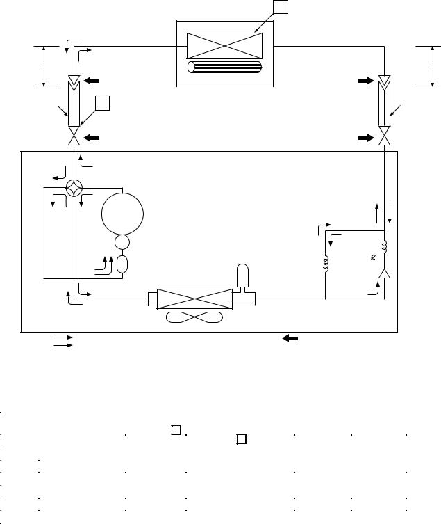
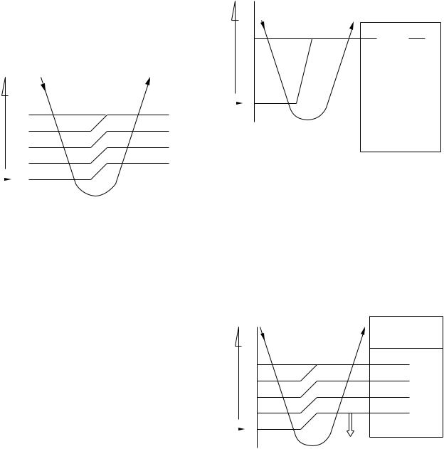
5. REFRIGERANT CYCLE DIAGRAM
RAS-10YKH-E / RAS-10YAH-E
|
Cooling |
0,39m |
Heating |
|
|
(Connecting pipe) |
|
ø9,52 |
|
T
Indoor unit |
Evaporator |
Cross flow fan |
0,49m (Connecting pipe) ø6,35
O.D.:9,52mm |
P |
|
|
O.D.:6,35mm |
|
Packed valve |
|
|
Packed valve |
|
(ø9,52) |
|
|
(ø6,35) |
|
Heating |
|
|
|
Cooling |
4-way valve |
|
|
|
Heating |
Cooling Compressor |
PH120T1-4C |
|
|
|
|
|
|
Capillary tube |
|
Accumulator |
Dryer |
ø1,5x500 |
|
|
|
|
||
|
|
Condenser |
|
|
|
|
|
|
Refrigerant |
|
|
Propeller fan |
|
R-22 0,74kg |
|
Cooling |
Outdoor unit |
Mark( |
)means check points of Gas Leak |
|
Heating |
|
|
|
|
|
Standard |
Surface temp. of heat |
Fan speed |
Ambient temp. |
|
|
50Hz |
pressure P |
exchanger interchanging |
conditions DB/WB (°C) |
||
|
(indoor) |
|||||
|
|
(kg/cm²G) |
pipe T (°C) |
Indoor |
Outdoor |
|
|
|
|
||||
|
|
|
|
|
|
|
|
Standard |
15,0 |
40,0 |
High |
21/ - |
7/6 |
|
|
|
|
|
|
|
Heating |
High temperature *1 |
19–23 |
52,0–59,0 |
Low |
27/ - |
21/15 |
|
Low temperature |
12,5 |
35,0 |
High |
21/ - |
-10/-10 |
|
|
|
|
|
|
|
|
Standard |
6,0 |
12,0 |
High |
27/19 |
35/24 |
|
|
|
|
|
|
|
Cooling |
High temperature |
6,5 |
15,0 |
High |
32/23 |
43/26 |
|
|
|
|
|
|
|
|
Low temperature |
4,0 |
2,0 |
Low |
21/15 |
21/15 |
|
|
|
|
|
|
|
Note : Measure the heat exchanger temperature at the center of U-bend. (By means of TC sensor.)
*1 : During heating overload, the high temperature limit control operation is included.
– 15 –

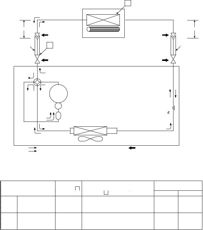
RAS-13YKH-E / RAS-13YAH-E
|
Cooling |
0,49m |
Heating |
|
|
(Connecting pipe) |
|
ø12,7 |
|
T
Indoor unit
Heat exchanger |
Cross flow fan |
0,39m (Connecting pipe) ø6,35
O.D.:12,7mm |
P |
O.D.:6,35mm |
|
Packed valve |
Packed valve |
|
(ø12,7) |
(ø6,35) |
|
Gas container connection (Reinstall etc.) |
|
|
Heating |
|
|
|
|
Cooling |
4-way valve |
|
|
|
|
|
|
|
Capillary tube |
|
|
Heating |
Cooling Compressor |
|
ø0,6x1500 |
|
|
PH170T2-4L2 |
|
|
|
||
|
|
|
|
|
Capillary tube |
|
Accumulator |
Capillary tube |
ø1,2x400 |
||
|
|
||||
|
|
ø1,7x400 |
|
||
|
|
|
|
|
|
|
|
Condenser |
|
|
|
|
|
|
|
Refrigerant |
|
|
|
Propeller fan |
|
R-22 |
0,88kg |
|
Cooling |
Outdoor unit |
Mark( |
)means check points of Gas Leak |
|
|
Heating |
|
|
|
|
|
|
Standard |
Surface temp. of heat |
Fan speed |
Ambient temp. |
|
|
50Hz |
pressure P |
exchanger interchanging |
conditions DB/WB (°C) |
||
|
(indoor) |
|||||
|
|
(kg/cm²G) |
pipe T (°C) |
Indoor |
Outdoor |
|
|
|
|
||||
|
|
|
|
|
|
|
|
Standard |
15,0 |
43,0 |
High |
21/ - |
7/6 |
|
|
|
|
|
|
|
Heating |
High temperature *1 |
19–23 |
52,0–59,0 |
Low |
27/ - |
21/15 |
|
Low temperature |
12,5 |
35,0 |
High |
21/ - |
-10/-10 |
|
|
|
|
|
|
|
|
Standard |
5,0 |
10,0 |
High |
27/19 |
35/24 |
|
|
|
|
|
|
|
Cooling |
High temperature |
6,0 |
14,0 |
High |
32/23 |
43/26 |
|
|
|
|
|
|
|
|
Low temperature |
4,0 |
2,0 |
Low |
21/15 |
21/15 |
|
|
|
|
|
|
|
Note : Measure the heat exchanger temperature at the center of U-bend. (By means of TC sensor.)
*1 : During heating overload, the high temperature limit control operation is included.
– 16 –
RAS-07YKH-E / RAS-07YAH-E
|
|
Indoor unit |
T |
|
|
|
|
|
Cooling |
Evaporator |
|
|
|
|
|
0,39m |
Heating |
|
0,49m |
|
|
(Connecting pipe) |
|
(Connecting pipe) |
|
||
ø9,52 |
|
Cross flow fan |
ø6,35 |
|
|
|
|
O.D.:9,52mm |
P |
|
O.D.:6,35mm |
|
Packed valve |
|
Packed valve |
|
(ø9,52) |
|
(ø6,35) |
|
Heating |
|
|
Cooling |
4-way valve |
|
|
Heating |
Cooling Compressor |
PH80T1-4C |
|
|
|
|
Capillary tube |
|
|
Dryer |
ø1,5x1400 |
|
Accumulator |
|
|
|
|
Condenser |
|
|
|
|
Refrigerant |
|
Propeller fan |
|
R-22 0,63kg |
Cooling |
Outdoor unit |
Mark( |
)means check points of Gas Leak |
Heating |
|
|
|
|
|
Standard |
Surface temp. of heat |
Fan speed |
Ambient temp. |
|||||
|
|
|
|
|
|
|
|
conditions DB/WB (°C) |
||
|
50Hz |
pressure |
P |
|
exchanger interchanging |
|||||
|
|
(indoor) |
||||||||
|
|
|
|
|
|
|
|
|
|
|
|
|
(kg/cm²G) |
pipe |
T |
(°C) |
Indoor |
Outdoor |
|||
|
|
|
||||||||
|
|
|
|
|
|
|
|
|
||
|
Standard |
15,0 |
|
|
40,0 |
High |
21/ - |
7/6 |
||
|
|
|
|
|
|
|
||||
Heating |
High temperature *1 |
19–23 |
52,0–59,0 |
Low |
27/ - |
21/15 |
||||
|
Low temperature |
12,5 |
|
|
35,0 |
High |
21/ - |
-10/-10 |
||
|
|
|
|
|
|
|
|
|
|
|
|
Standard |
6,0 |
|
|
12,0 |
High |
27/19 |
35/24 |
||
|
|
|
|
|
|
|
|
|
||
Cooling |
High temperature |
6,5 |
|
|
15,0 |
High |
32/23 |
43/26 |
||
|
Low temperature |
4,0 |
|
|
2,0 |
Low |
21/15 |
21/15 |
||
|
|
|
|
|
|
|
|
|
|
|
Note : Measure the heat exchanger temperature at the center of U-bend. (By means of TC sensor.)
*1 : During heating overload, the high temperature limit control operation is included.
– 17 –

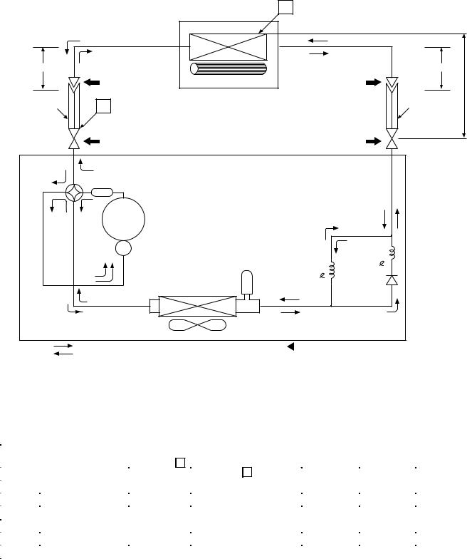
RAS-10YKH-ES / RAS-10YAH-ES
|
Cooling |
0,39m |
Heating |
|
|
(Connecting pipe) |
|
ø9,52 |
|
T
Indoor unit |
Evaporator |
Cross flow fan |
0,49m (Connecting pipe) ø6,35
O.D.:9,52mm |
P |
O.D.:6,35mm |
|
Packed valve |
Packed valve |
|
(ø9,52) |
(ø6,35) |
|
Heating |
|
Cooling |
4-way valve |
Muffler |
|
Muffler |
|
|
|
Heating Cooling Compressor PA118X1T-4FZ
|
|
|
|
Capillary tube |
|
Dryer |
Capillary tube |
ø0,8x400 |
|
|
Accumulator |
|
ø1,2x400 |
|
|
|
|
|
|
|
Condenser |
|
|
|
|
|
|
Refrigerant |
|
|
Propeller fan |
|
R-410A 0,69kg |
|
Cooling |
Outdoor unit |
Mark( |
)means check points of Gas Leak |
|
Heating |
|
|
|
|
|
|
Standard |
Surface temp. of heat |
Fan speed |
Ambient temp. |
|
|
50Hz |
pressure P |
exchanger interchanging |
conditions DB/WB (°C) |
||
|
(indoor) |
|||||
|
|
(MPaG) |
pipe T (°C) |
Indoor |
Outdoor |
|
|
|
|
||||
|
|
|
|
|
|
|
|
Standard |
2,5 |
43,0 |
High |
20/ - |
7/6 |
|
|
|
|
|
|
|
Heating |
High temperature *1 |
3,1–3,6 |
51,0–58,0 |
Low |
27/ - |
21/15 |
|
Low temperature |
2,2 |
36,0 |
High |
20/ - |
-10/-10 |
|
|
|
|
|
|
|
|
Standard |
0,9 |
10,0 |
High |
27/19 |
35/24 |
|
|
|
|
|
|
|
Cooling |
High temperature |
1,1 |
16,0 |
High |
32/23 |
43/26 |
|
|
|
|
|
|
|
|
Low temperature |
0,6 |
2,0 |
Low |
21/15 |
21/15 |
|
|
|
|
|
|
|
Note : Measure the heat exchanger temperature at the center of U-bend. (By means of TC sensor.)
*1 : During heating overload, the high temperature limit control operation is included.
– 18 –
RAS-13YKH-ES / RAS-13YAH-ES
T
Indoor unit
Heat exchanger
Cooling
0,49m (Connecting pipe)
ø9,52
Cross flow fan
(Note)
Maximum pipe length is 15m Maximum pipe head is 6m
0,39m (Connecting pipe) ø6,35
O.D.:9,52mm |
P |
O.D.:6,35mm |
|
Packed valve |
Packed valve |
|
(ø9,52) |
(ø6,35) |
|
Gas container connection (Reinstall etc.) |
|
|
Heating |
|
|
Cooling |
4-way valve |
|
|
|
Muffler |
|
|
Heating |
Cooling Compressor PA160X2T-4FM |
|
|
|
|
|
Capillary tube |
|
Dryer |
Capillary tube |
ø1,5x500 |
|
|
ø1,2x1200 |
|
|
Condenser |
|
|
|
|
Refrigerant |
|
|
Propeller fan |
R-410A 0,80kg |
|
Cooling |
Outdoor unit |
Mark( |
|
)means check points of Gas Leak |
|
||||
|
||||
Heating |
|
|
|
|
|
|
Standard |
Surface temp. of heat |
Fan speed |
Ambient temp. |
|
|
50Hz |
pressure P |
exchanger interchanging |
conditions DB/WB (°C) |
||
|
(indoor) |
|||||
|
|
(MPaG) |
pipe T (°C) |
Indoor |
Outdoor |
|
|
|
|
||||
|
|
|
|
|
|
|
|
Standard |
2,7 |
43,0 |
High |
20/ - |
7/6 |
|
|
|
|
|
|
|
Heating |
High temperature *1 |
3,2–3,6 |
52,0–57,0 |
Low |
27/ - |
21/15 |
|
Low temperature |
2,0 |
30,0 |
High |
20/ - |
-10/-10 |
|
|
|
|
|
|
|
|
Standard |
0,9 |
11,0 |
High |
27/19 |
35/24 |
|
|
|
|
|
|
|
Cooling |
High temperature |
1,0 |
14,0 |
High |
32/23 |
43/26 |
|
|
|
|
|
|
|
|
Low temperature |
0,6 |
2,0 |
Low |
21/15 |
21/15 |
|
|
|
|
|
|
|
Note : Measure the heat exchanger temperature at the center of U-bend. (By means of TC sensor.)
*1 : During heating overload, the high temperature limit control operation is included.
– 19 –

RAS-07YKH-ES / RAS-07YAH-ES
|
|
Indoor unit |
T |
|
|
|
|
|
Cooling |
Evaporator |
|
|
|
|
|
0,39m |
Heating |
|
0,49m |
|
|
(Connecting pipe) |
|
(Connecting pipe) |
|
||
ø9,52 |
|
Cross flow fan |
ø6,35 |
|
|
|
|
O.D.:9,52mm |
P |
|
O.D.:6,35mm |
|
Packed valve |
|
Packed valve |
|
(ø9,52) |
|
(ø6,35) |
|
Heating |
|
|
Cooling |
4-way valve |
|
|
Heating |
Cooling Compressor |
PA79X1T-4FZ5 |
|
|
|
|
Capillary tube |
|
|
Dryer |
ø1,2x900 |
|
Accumulator |
|
|
|
|
Condenser |
|
|
|
|
Refrigerant |
|
Propeller fan |
|
R-410A 0,73kg |
Cooling |
Outdoor unit |
Mark( |
)means check points of Gas Leak |
Heating |
|
|
|
|
|
Standard |
Surface temp. of heat |
Fan speed |
Ambient temp. |
|||||
|
|
|
|
|
|
|
|
conditions DB/WB (°C) |
||
|
50Hz |
pressure |
P |
|
exchanger interchanging |
|||||
|
|
(indoor) |
||||||||
|
|
|
|
|
|
|
|
|
|
|
|
|
(kg/cm²G) |
pipe |
T (°C) |
Indoor |
Outdoor |
||||
|
|
|
||||||||
|
|
|
|
|
|
|
|
|
|
|
|
Standard |
2,5 |
|
|
43,0 |
|
High |
20/ - |
7/6 |
|
|
|
|
|
|
|
|
|
|
||
Heating |
High temperature *1 |
3,1-3,6 |
|
|
51,0–58,0 |
Low |
27/ - |
21/15 |
||
|
|
|
|
|
|
|
|
|
||
|
Low temperature |
2,2 |
|
|
36,0 |
High |
20/ - |
-10/-10 |
||
|
|
|
|
|
|
|
|
|
|
|
|
Standard |
0,9 |
|
|
10,0 |
High |
27/19 |
35/24 |
||
|
|
|
|
|
|
|
|
|
||
Cooling |
High temperature |
1,1 |
|
|
16,0 |
High |
32/23 |
43/26 |
||
|
Low temperature |
0,6 |
|
|
2,0 |
Low |
21/15 |
21/15 |
||
|
|
|
|
|
|
|
|
|
|
|
Note : Measure the heat exchanger temperature at the center of U-bend. (By means of TC sensor.)
*1 : During heating overload, the high temperature limit control operation is included.
– 20 –
– 21 –
|
Main Unit Control Panel |
C. P. U |
|
Functions |
|
Heat Exchanger Sensor |
|
|
|
|
|
|
|
|
Thermo. Sensor |
|
• Louver Control |
|
|
|
|
|
|
Current Sensor |
|
• 3-minutes Delay at Restart for Compressor |
|
|
|
(Compressor Current) |
|
|
Infrared Rays Signal Receiver |
|
|
|
|
|
Infrared
Rays
Remote Control
Operation (START/STOP)
Operation Mode Selection
AUTO, COOL, DRY, HEAT, FAN ONLY
Thermo. Setting
Fan Speed Selection
ON TIMER Setting
OFF TIMER Setting
Louver AUTO Swing
Louver Direction Setting
ECONO.
AC 220/230/240V ~ 50Hz
Initializing Circuit |
|
• Motor Revolution Control |
|
|
|
|
|
|
||||||
|
|
|
|
|
|
|
|
|
|
|
|
|
|
|
Clock Frequency |
|
• Processing |
|
|
|
|
|
|
||||||
Oscillator Circuit |
|
|
|
|
|
|
|
|
||||||
|
|
(Temperature Processing) |
|
|
|
|
|
|
||||||
|
|
|
|
|
|
|
|
|
|
|||||
|
|
|
|
• Timer |
|
|
|
|
|
|
|
|
|
|
|
|
|
|
|
|
|
|
|
|
|
|
|
||
|
|
|
|
|
|
|
|
|
|
|
|
|
|
|
|
|
|
|
|
|
|
|
|
|
|
|
|
|
|
|
|
|
|
|
|
|
|
|
|
|
|
|
|
|
Power Supply |
|
|
Compressor |
|
Outdoor Fan |
|
4-Way Valve |
|
Louver |
|
||||
Circuit |
|
ON/OFF Signal |
|
ON/OFF Signal |
|
ON/OFF Signal |
|
ON/OFF Signal |
|
|||||
|
|
|
|
|
|
|
|
|
|
|
|
|
|
|
|
|
|
|
|
|
|
|
|
|
|
|
|
|
|
|
|
|
|
|
|
|
|
|
|
|
|
|
|
|
Noise Filter |
|
|
|
|
|
Relay Driver, Louver Driver |
|
|
|
|||||
|
|
|
|
|
|
|
||||||||
|
|
|
|
|
|
|
|
|
|
|
|
|
|
|
|
|
|
|
Relay |
|
Relay |
Relay |
|
||||||
|
|
|
|
RY01 |
RY03 |
RY04 |
|
|||||||
Relay
RY02
Compressor |
|
Outdoor Fan Motor |
|
4-Way Valve |
|
|
|
|
|
Operation
Display
Timer
Display
ECONO.
Sign Display
PRE-DEF.
Sign Display
Indoor
Fan Motor
Louver
Motor
DIAGRAM BLOCK CONTROL .6
7. OPERATION DESCRIPTIONS
7-1. FAN ONLY Operation
(MODE of the remote control : FAN ONLY)
(1)During this mode, the relay RY01 is always turned off so that only the indoor fan is operated. RY02 is always turnd on.
1)When the FAN is set to AUTO, the indoor fan motor operates as shown in Fig. 7-1-1.
2)When the FAN is set to LOW, MED, or HIGH, the indoor fan motor operates with a constant in volume as listed in Table 7-1-1.
temp.) |
|
|
||
Set– |
28 |
|
||
|
|
|
||
temp. |
27 |
HIGH |
||
|
||||
26 |
MED |
|||
|
|
|||
(Room |
LOW(+) |
|||
25 |
||||
|
|
|||
|
|
|
||
Set |
|
24 |
LOW |
|
|
|
|||
|
|
|||
temp. |
|
LOW |
||
|
|
|
|
|
Fig. 7-1-1 Auto setting of air volume
Table 7-1-1 Manual setting of FAN SPEED
Indication of |
HIGH Air volume (m3/hr) |
||
RAS-10YKH-E |
RAS13-YKH-E |
||
FAN SPEED |
|||
|
RAS-10YKH-ES |
RAS13-YKH-ES |
|
|
|
|
|
LOW |
400 (430)* |
510 |
|
|
|
|
|
MED |
500 (490)* |
560 |
|
|
|
|
|
HIGH |
600 (550)* |
650 |
|
|
|
|
|
*For model : RAS-07YKH-E, RAS-07YKH-ES
(2)Once the setting is made, the operation mode is memorized in the microcomputer so that the same operation can be effected thereafter simply
by pushing the START/STOP button.
7-2. COOL Operation
(MODE of the remote control : COOL)
(1)Compressor, 4-way valve, outdoor fan and operation display are controlled as shown in Fig. 7-2-1.
temp.) |
|
ON |
|
|
ON |
|
|
|
|
|
|
||||
Set– |
+1 |
|
|
|
|||
|
|
|
|
|
|||
|
|
|
|
|
|
|
|
temp. |
|
OFF |
ON |
OFF |
OFF |
ON |
|
|
|
|
|||||
(Room |
|
|
|
|
|||
|
|
|
|
|
|
||
Set |
|
0 |
|
|
|
|
|
temp. |
|
Compressor (RY01) |
relayCommon (RY02) |
valveway-4 (RY04) |
fanOutdoor (RY03) |
OPERATION display |
|
|
|
|
|
|
|
||
|
|
|
|
|
|
|
|
Fig. 7-2-1
(2)Relays RY01 and RY02 are turned on to energize the outdoor unit, and a cool operation is carried out.
1)When the FAN is set to AUTO, the indoor fan motor operates as shown in Fig. 7-2-2.
2)When the FAN is set to LOW, MED, or HIGH, the indoor fan motor operates with a constant in volume as listed in Table 7-1-1.
|
|
|
|
FAN |
|
temp.) |
|
|
|
|
|
|
|
AUTO |
Manual |
||
|
|
|
|
||
Set– |
+4 |
|
HIGH |
|
|
|
MED |
|
|||
|
|
|
|
|
|
temp. |
+3 |
|
LOW(+) |
to the set |
|
|
|
|
|
|
According |
(Room |
+2 |
|
|
position |
|
|
|
LOW |
|||
+1 |
|
|
|||
|
|
|
|
||
|
|
|
|
|
|
Set |
|
0 |
|
LOW |
|
|
|
(continuous) |
|
||
|
|
||||
temp. |
|
|
|
|
|
|
RY01 |
|
|||
|
|
|
|
||
|
|
|
OFF |
|
|
Fig. 7-2-2
(3)Once the setting is made, the operation mode is memorized in the microcomputer so that the same operation can be effected thereafter simply by pushing the START/STOP button.
– 22 –
Loading...