


FILE NO. SVM-02005(1)
SERVICE MANUAL
AIR-CONDITIONER
SPLIT WALL TYPE
RAS-13UKP-ES / RAS-13UA-ES RAS-10UKP-ES / RAS-10UA-ES RAS-07UKP-ES / RAS-07UA-ES
|
|
|
07 Class |
10/13 Class |
|
Revised on May, 2002
FILE NO. SVM-02005(1)
CONTENTS
1.SPECIFICATIONS
2.CONSTRUCTION VIEWS
2-1 Indoor Unit
2-2 Outdoor Unit (RAS-13UA-ES) 2-3. Outdoor Unit (RAS-10UA-ES) 2-4. Outdoor Unit (RAS-07UA-ES)
3.WIRING DIAGRAM
4.SPECIFICATION OF ELECTRICAL PARTS
4-1 Indoor Unit
4-2 Outdoor Unit (RAS-13UA-ES)
4-3 Outdoor Unit (RAS-10UA-ES, RAS-07UA-ES)
5.REFRIGERATION CYCLE DIAGRAM
5-1 RAS-13UKP-ES / RAS-13UA-ES 5-2 RAS-10UKP-ES / RAS-10UA-ES 5-3 RAS-07UKP-ES / RAS-07UA-ES
6.CONTROL BLOCK DIAGRAM
7.OPERATION DESCRIPTION
7-1 Outline of Air Conditioner Control
7-2 Description of Operation Circuit
7-3 Hi POWER Mode
7-4 High-Temperature Limit Control
7-5 Low-Temperature Limit Control
7-6 Auto Restart Function
7-7 Filter Check Lamp
8.INSTALLATION PROCEDURE
8-1 Safety Cautions
8-2 Installation Diagram of Indoor and Outdoor Units 8-3 Installation
8-4 Indoor Unit
8-5 Outdoor Unit
8-6 How to Set Remote Control Selector Switch 8-7 Others
9.TROUBLESHOOTING CHART
9-1 Troubleshooting Procedure
9-2 Basic Check Items
9-3 Primary Judgement
9-4 Self-Diagnosis by Remote Control (Check Code) 9-5 Troubleshooting Flowcharts
9-6 Troubleshooting for Remote Control (Including The Indoor P.C. Board)
–1 –

FILE NO. SVM-02005(1)
10.PARTS REPLACEMENT
10-1 Indoor Unit
10-2 Outdoor Unit (RAS-13UA-ES) 10-3 Outdoor Unit (RAS-10UA-ES) 10-4 Outdoor Unit (RAS-07UA-ES)
11.EXPLODED VIEWS AND PARTS LIST
11-1 Indoor Unit (E-Parts Assy)
11-2 Indoor Unit
11-3 Outdoor Unit (RAS-13UA-ES)
11-4 Outdoor Unit (RAS-10UA-ES)
11-5 Outdoor Unit (RAS-07UA-ES)
•This air conditioner is charged with HFC (R-410A) that doesn’t deplete the
Ozone layer.
• This air conditioner requires special installation for the refrigerant R-410A.
– 2 –
FILE NO. SVM-02005(1)
1. SPECIFICATIONS
|
|
MODEL |
RAS-13UKP-ES |
|
RAS-10UKP-ES |
|
RAS-07UKP-ES |
||||||||
|
|
|
|
|
RAS-13UA-ES |
|
RAS-10UA-ES |
|
RAS-07UA-ES |
||||||
|
|
|
|
|
|
|
|
|
|
|
|
|
|
|
|
ITEM |
|
|
|
|
|
|
|
Cooling |
|
|
|
||||
|
|
|
|
|
|
|
|
|
|
|
|
|
|
|
|
Capacity |
|
|
|
220V |
|
240V |
|
220V |
|
240V |
|
220V |
|
240V |
|
|
|
|
|
|
|
|
|
|
|
|
|
|
|
||
|
|
kW |
3.70 |
|
3.75 |
|
2.65 |
|
2.70 |
|
2.15 |
|
2.18 |
||
|
|
|
|
|
|
|
|
|
|||||||
|
|
|
|
|
|
|
|
|
|
|
|
|
|
|
|
|
|
|
Phase |
|
|
|
|
|
1 |
|
|
|
|||
Power source |
|
|
V |
|
|
|
|
220 – 240 |
|
|
|
||||
|
|
|
|
|
|
|
|
|
|
|
|
|
|
|
|
|
|
|
|
Hz |
|
|
|
|
|
50 |
|
|
|
|
|
|
|
|
|
|
|
|
|
|
|
|
|
|
|
|
|
Power consumption |
kW |
1.25 |
|
1.29 |
|
0.77 |
|
0.83 |
|
0.66 |
|
0.68 |
|||
|
|
|
|
|
|
|
|
|
|
|
|
|
|
|
|
Power factor |
|
|
% |
98 |
|
95 |
|
92 |
|
92 |
|
97 |
|
90 |
|
|
|
|
|
|
|
|
|
|
|
|
|
|
|
|
|
Running |
Indoor |
A |
|
|
|
|
|
0.15 |
|
|
|
|
|||
|
|
|
|
|
|
|
|
|
|
|
|
|
|
|
|
current |
Outdoor |
A |
5.66 |
|
5.53 |
|
3.65 |
|
3.60 |
|
2.95 |
|
3.00 |
||
|
|
|
|
|
|
|
|
|
|
|
|
|
|
|
|
Starting current |
A |
|
24 |
|
|
16 |
|
|
12 |
||||||
|
|
|
|
|
|
|
|
|
|
|
|
|
|
|
|
Moisture removal |
lit/h |
|
2.0 |
|
|
1.2 |
|
|
0.8 |
||||||
|
|
|
|
|
|
|
|
|
|
|
|
|
|
||
Noise |
Indoor (H/M/L) |
dB |
|
41/35/31 |
|
39/33/26 |
|
|
38/32/26 |
||||||
|
|
|
|
|
|
|
|
|
|
|
|
|
|
||
|
|
Outdoor (220-240V) |
dB |
46 |
|
47 |
|
46 |
|
47 |
|
44 |
|
45 |
|
|
|
|
|
|
|
|
|
|
|
|
|
|
|
||
Refrigerant |
Name of refrigerant |
|
|
|
|
|
R-410A |
|
|
|
|||||
|
|
|
|
|
|
|
|
|
|
|
|
|
|
||
|
|
Rated amount |
kg |
|
0.86 |
|
|
0.65 |
|
|
0.65 |
||||
|
|
|
|
|
|
|
|
|
|
|
|
|
|||
Refrigerant control |
|
|
|
|
|
Capillary tube |
|
|
|
||||||
|
|
|
|
|
|
|
|
|
|
|
|
|
|
|
|
|
|
Gas side size |
mm |
|
|
|
|
|
9.52 |
|
|
|
|
||
|
|
Connection type |
|
|
|
|
|
Flare connection |
|
|
|
||||
|
|
|
|
|
|
|
|
|
|
|
|
|
|
|
|
|
|
Liquid side size |
mm |
|
|
|
|
|
6.35 |
|
|
|
|
||
Interconnection |
Connection type |
|
|
|
|
|
Flare connection |
|
|
|
|||||
|
|
|
|
|
|
|
|
|
|
|
|
|
|
|
|
pipe |
Maximum length |
m |
|
15*1 |
|
|
10*1 |
|
|
|
|||||
|
|
(One way) |
|
|
|
|
|
|
|||||||
|
|
|
|
|
|
|
|
|
|
|
|
|
|
||
|
|
|
|
|
|
|
|
|
|
|
|
|
|
|
|
|
|
Maximum height |
m |
|
6 |
|
|
5 |
|
|
|
||||
|
|
difference |
|
|
|
|
|
|
|||||||
|
|
|
|
|
|
|
|
|
|
|
|
|
|
||
|
|
|
|
|
|
|
|
|
|
|
|
|
|||
INDOOR UNIT |
|
|
|
RAS-13UKP-ES |
|
RAS-10UKP-ES |
|
RAS-07UKP-ES |
|||||||
|
|
|
|
|
|
|
|
|
|
|
|
|
|
|
|
|
|
Height |
mm |
|
|
|
|
|
275 |
|
|
|
|
||
|
|
|
|
|
|
|
|
|
|
|
|
|
|
|
|
Dimensions |
Width |
mm |
|
|
|
|
|
790 |
|
|
|
|
|||
|
|
|
|
|
|
|
|
|
|
|
|
|
|
|
|
|
|
Depth |
mm |
|
|
|
|
|
208 |
|
|
|
|
||
|
|
|
|
|
|
|
|
|
|
|
|
|
|
|
|
Net weight |
|
|
kg |
|
|
|
|
|
10 |
|
|
|
|
||
|
|
|
|
|
|
|
|
|
|
|
|
|
|||
Evaporator type |
|
|
|
|
|
Finned tube |
|
|
|
||||||
|
|
|
|
|
|
|
|
|
|
|
|
|
|
|
|
Indoor fan type |
|
|
|
|
|
|
|
Cross flow fan |
|
|
|
||||
|
|
|
|
|
|
|
|
|
|
|
|
|
|
|
|
|
|
High fan |
m3/h |
|
630 |
|
|
630 |
|
|
570 |
||||
Air volume |
Medium fan |
m3/h |
|
550 |
|
|
490 |
|
|
460 |
|||||
|
|
Low fan |
m3/h |
|
460 |
|
|
370 |
|
|
340 |
||||
Fan motor output |
W |
|
|
|
|
|
30 |
|
|
|
|
||||
|
|
|
|
|
|
|
|
|
|
|
|
|
|
|
|
Air filter |
|
|
|
|
|
|
Honeycomb woven filter with PP frame |
|
|
|
|||||
|
|
|
|
|
|
|
|
|
|
|
|||||
OUTDOOR UNIT |
|
RAS-13UA-ES |
|
RAS-10UA-ES |
|
RAS-07UA-ES |
|||||||||
|
|
|
|
|
|
|
|
|
|
|
|
|
|
|
|
|
|
Height |
mm |
|
538 |
|
|
530 |
|
|
530 |
||||
|
|
|
|
|
|
|
|
|
|
|
|
|
|
|
|
Dimensions |
Width |
mm |
|
780 |
|
|
770 |
|
|
660 |
|||||
|
|
|
|
|
|
|
|
|
|
|
|
|
|
|
|
|
|
Depth |
mm |
|
300 |
|
|
200 |
|
|
240 |
||||
|
|
|
|
|
|
|
|
|
|
|
|
|
|
|
|
Net weight |
|
|
kg |
|
39 |
|
|
29 |
|
|
27 |
||||
|
|
|
|
|
|
|
|
|
|
|
|
|
|||
Condenser type |
|
|
|
|
|
Finned tube |
|
|
|
||||||
|
|
|
|
|
|
|
|
|
|
|
|
|
|||
Outdoor fan type |
|
|
|
|
|
Propeller fan |
|
|
|
||||||
|
|
|
|
|
|
|
|
|
|
|
|
|
|
|
|
Airflow volume |
|
|
m3/h |
1700 |
|
1900 |
|
1500 |
|
1700 |
|
1420 |
|
1520 |
|
Fan motor output |
W |
|
|
|
|
|
30 |
|
|
|
|
||||
|
|
|
|
|
|
|
|
|
|
|
|
||||
Compressor |
|
Model |
|
PA150X2T-4FM |
|
PA98X1T-4FZ |
|
PA79X1T-4FZ5 |
|||||||
|
|
|
|
|
|
|
|
|
|
|
|
|
|
|
|
|
Output |
W |
|
1100 |
|
|
750 |
|
|
605 |
|||||
|
|
|
|
|
|
|
|||||||||
|
|
|
|
|
|
|
|
|
|
|
|
|
|
||
Safety device |
|
|
|
|
|
|
|
Fuse, Overload relay |
|
|
|
||||
|
|
|
|
|
|
|
|
|
|
|
|
|
|
||
Louver type |
|
|
|
|
|
|
|
Automatic louver |
|
|
|
||||
|
|
|
|
|
|
|
|
|
|
|
|
||||
Usable outdoor temperature range |
°C |
|
|
|
21 ~ 43 |
|
|
|
|
||||||
|
|
|
|
|
|
|
|
|
|
|
|
|
|
|
|
– 3 –
FILE NO. SVM-02005(1)
Note : 1
•Capacity is based on the following temperature conditions.
Condition |
JIS C9612-1994 |
|
|
Temperature |
Cooling |
(DB) |
27°C |
Indoor unit inlet air temperature |
|
(WB) |
19°C |
(DB) |
35 °C |
Outdoor unit inlet air temperature |
|
(WB) |
24 °C |
Note : 2 |
|
•Charge refrigerant according to the table below.
|
Refrigerant |
RAS-13UKP-ES / RAS-13UA-ES |
RAS-10UKP-ES / RAS-10UA-ES |
|
RAS-07UKP-ES / RAS-07UA-ES |
||
|
|
|
|
|
|
|
|
*1 |
No need to charge |
15m or less |
10m or less |
|
refrigerant |
||
|
|
|
|
|
|
|
|
– 4 –

FILE NO. SVM-02005(1)
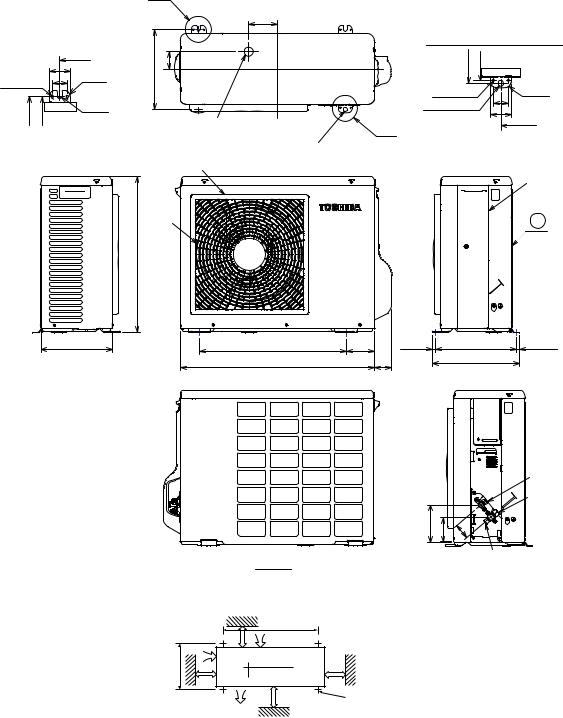
2. CONSTRUCTION VIEWS
2-1. Indoor Unit
Front panel |
Air inlet |
Air filter |
Heat exchanger |
|
|||
Back body |
|
790 |
208 |
|
|
|
275
6 60
|
|
60 |
Air outlet |
48 |
6 |
|
||
|
|
Knock out system
Knock out system
48
|
64 |
53 |
120 |
590 |
80 |
|
Hanger |
|
Drain hose (0.54m)
Hanger
|
45 |
|
|
Minimum |
|
|
distance |
|
275 |
to ceiling |
|
170 or more |
||
|
90 150
|
|
|
Connecting pipe (0.43m) |
|
|
||
|
320 |
|
(Flare |
6.35) |
|
|
|
|
|
|
Connecting pipe (0.33m) |
|
|
||
|
|
|
Flare ( 9.52) |
|
|
|
|
|
620 |
|
|
For stud bolt |
|
|
|
235 |
|
235 |
|
|
|
||
215 |
more |
215 |
|
( 8~ 10) |
|
|
|
Minimum |
Hanger |
For stud bolt ( |
6) |
|
|||
|
|
||||||
distance |
65or |
26 |
|
|
|
||
to ceiling |
|
|
|
|
|
||
|
|
|
|
|
45 |
|
|
|
|
|
|
Minimum |
|
|
|
|
|
|
|
distance |
190 |
|
160 |
|
|
|
|
to ceiling |
|
||
|
|
|
|
|
|
|
|
|
|
|
|
170 or more |
|
|
|
|
|
|
|
32 |
40 |
|
|
Hanger |
|
Hanger |
|
57 |
18 |
||
|
|
|
|||||
160 |
160 |
150 |
90 |
|
Wireless remote control |
||
|
|
|
|||||
Installation plate outline
Center line
– 5 –
FILE NO. SVM-02005(1)
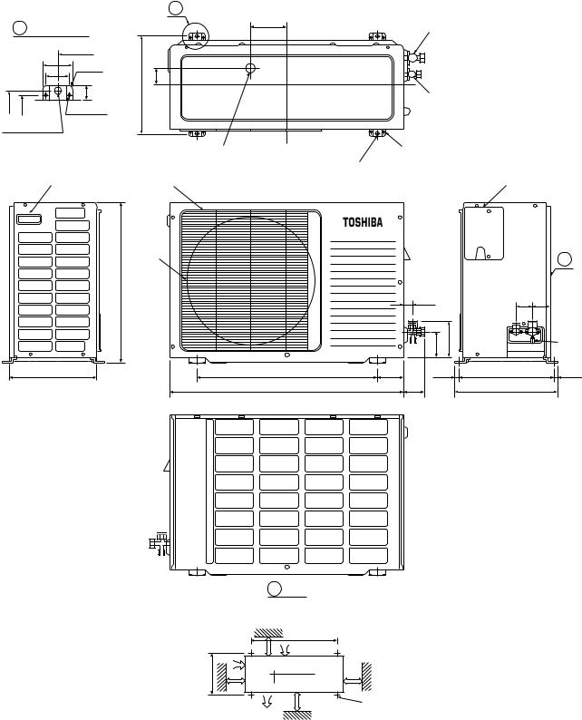
2-2. Outdoor Unit (RAS-13UA-ES)
A Detail Drawing
|
|
600 |
|
50 |
R10 |
|
36 |
|
|
|
|
325 |
301 |
23 |
6 hole |
||
|
11x14 hole |
|
A
|
|
120 |
Gas side (Flare 9.52) |
|
|
|
|
325 |
52.5 |
|
Liquid side (Flare 6.35) |
|
|
|
|
|
|
25Drain outlet |
8- 6 hole (for fixing outdoor unit) |
|
|
4- 11x14 hole (for 8- 10 anchor bolt)
Handle |
Fan guard |
|
|
|
|
420 |
|
|
|
538 |
|
|
27 |
|
|
|
|
|
|
|
|
|
100 |
130 |
300 |
600 |
90 |
(8.5) |
|
|
780 |
|
59 |
|
Electric parts cover
|
Z |
54 61 |
|
|
Service |
|
port |
325 (pitch) |
(8.5) |
342 |
|
Z View
Installation dimension
100 or more |
600 |
|
Air inlet 600 or more |
||
|
||
325 |
|
|
100 or more |
600 or more 4x 11x14 Long holes (for 8- 10 anchor bolt) |
|
Air outlet |
|
– 6 –
FILE NO. SVM-02005(1)
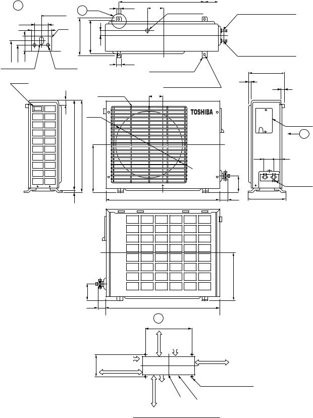
2-3. Outdoor Unit (RAS-10UA-ES)
|
|
A Detail Drawing |
A |
36 |
|||
|
|
|
|
600 |
|
||
|
|
|
36 |
|
R10 |
|
|
|
|
|
50 |
|
|
|
|
|
|
|
|
|
230 |
216 |
30 |
|
230 |
216 |
25 |
|
|
|
50 |
11x14 Hole |
6 Hole |
|
|||||
|
|
||||||
|
|
Handle |
|
|
|
|
|
|
|
|
|
|
11 |
|
Fan guard |
|
|
|
|
|
|
|
|
|
|
|
|
|
|
|
420 |
525 |
530 |
268
5
600 |
85 |
|
|
|
|
111 |
25 Drain hole |
|
|
|
Gas side (flare 9.52) |
|
|
|
|
||
|
|
|
|
|
|
|
|
|
|
|
|
|
|
|
|
|
|
|
Liquid side (flare 6.35) |
|
8- 6 Holes |
200 |
|
(For fixing the outdoor unit) |
12 |
|
4- 11x14 Long holes |
||
11 |
||
111 (For anchor bolt 8- |
||
10) |
|
|
Electric |
|
|
parts cover |
|
|
Z |
|
54 |
62 |
|
|
Access for |
|
89 |
charging |
|
|
|
770 |
59 |
250 |
89
230
268
59 |
770 |
|
|
Z View |
|
or more |
600 |
|
Air inlet |
||
45 |
600 or more |
|
Air inlet |
||
|
||
100 or more |
(Minimum distance |
|
|
of the wall) |
more |
Air |
4- 11x14 Long holes |
outlet |
(For anchor bolt 8- 10) |
|
or |
|
Center Visible outline of the product |
400 |
|
|
|
port |
Mounting dimension of anchor bolt
– 7 –
FILE NO. SVM-02005(1)
2-4. Outdoor Unit (RAS-07UA-ES)
A Detail Drawing (Back Leg)
660
|
|
|
50 |
R 15 |
|
6 Hole |
36 |
||
|
|
|||
|
273.5 |
265 |
|
R 5.5 |
|
|
|
|
|
530
|
A |
|
|
|
|
97 |
|
|
|
|
|
B Detail Drawing (Front Leg) |
||
273.5 |
59.5 |
273.5 |
265 |
|
|
|
6 Hole |
36 R 15 |
|
|
25Drain outlet |
11x14 Hole |
50 |
|
|
B |
|
660 |
|
|
|
|
|
|
|
|
2- 11x14 hole |
|
|
|
Fan guard |
(for 8- 10 anchor bolt) |
|
|
|
|
|
|
Cover PV |
|
420 |
|
|
Z |
242 |
500 |
97.5 |
(11) |
273.5 (pitch) |
(12.5) |
|
660 |
|
56 |
297 |
|
|
|
|
|
|
|
|
Liquid side |
|
|
|
|
(Flare |
6.35) |
|
|
|
Gas side |
|
|
126 |
48 |
(Flare |
9.52) |
|
54 |
|
||
|
Z View |
|
Service port |
|
|
|
|
|
|
Installation dimension |
|
|
|
|
100 or more |
600 |
|
|
|
Air inlet 600 or more |
|
|
|
|
|
|
|
|
|
325 |
|
|
|
|
100 or more |
600 or more 4x 11x14 Long holes (for 8- 10 anchor bolt) |
|||
Air outlet |
|
|
|
|
– 8 –
FILE NO. SVM-02005(1)
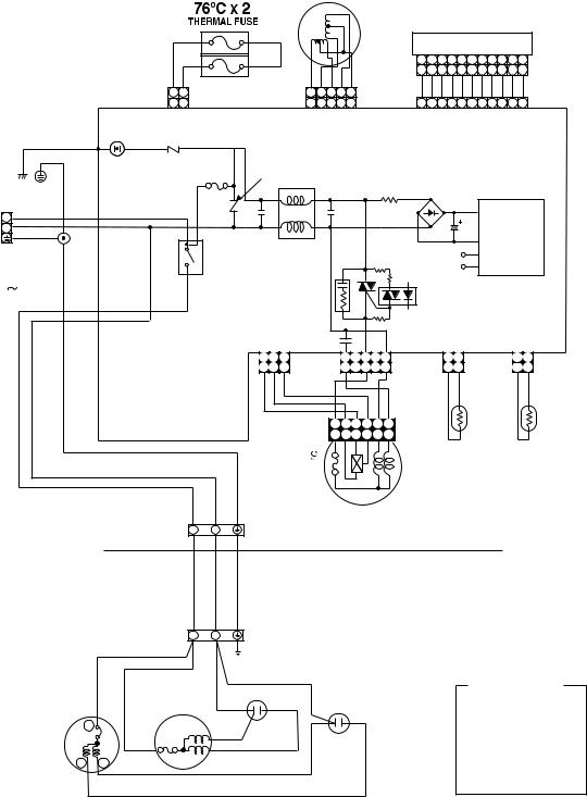
3. WIRING DIAGRAM
Louver motor
PNK |
PNK |
1 |
2 |
1 |
2 |
CN04 |
|
|
BLK P04 |
SG01 |
R22 |
|
|
||
|
GRN&YEL |
DSA |
VARISTOR |
|
|
||
POWER |
|
|
F01 |
TERMINAL |
|
T6.3A |
|
BLOCK |
|
|
|
BRW |
|
250V |
|
L |
|
||
|
|
||
BLU |
|
|
|
N |
|
|
|
GRN&YEL |
|
3 |
|
POWER SUPPLY |
|
RY01 |
|
|
|
||
SINGLE PHASE |
|
4 |
|
220-240V |
, |
|
|
|
|
||
50 Hz |
|
|
|
|
WHI |
|
|
INDOOR |
BLK |
WHI |
GRN&YEL |
|
|
|
|
TERMINAL |
|
1 |
2 |
BLOCK |
|
OUTDOOR
TERMINAL
BLOCK 1 2
BLK
|
|
|
|
INFRARED RAYS RECEIVE |
||||||||
|
|
|
|
AND INDICATION PARTS |
||||||||
|
|
|
CN25 |
1 |
2 3 |
4 |
5 |
6 |
7 |
8 |
9 10 11 |
|
YEL |
YEL YEL |
YEL WHI |
1 |
2 |
3 |
4 |
5 |
6 |
7 |
8 |
9 10 11 |
|
|
BLU |
BLU |
BLU |
BLU |
BLU |
BLU |
BLU |
BLU BLU BLU WHI |
||||
5 |
4 3 |
2 1 |
|
|||||||||
5 |
4 3 |
2 1 |
|
1 |
2 3 |
4 |
5 6 7 8 9 10 11 |
|||||
|
CN07 |
|
|
|
|
|
CN13 |
|
|
|||
|
|
|
|
|
|
|
MAIN P.C. BOARD |
|
|
|
|
|||||
|
R21 |
|
|
|
|
|
|
MCC-862 |
|
|
|
|
|
|||
|
VARISTOR |
|
|
|
|
|
|
|
|
|
|
|
|
|||
|
|
|
|
C01 |
|
|
|
R01 |
DB01 |
|
|
|
|
|
||
|
|
|
|
|
|
|
|
|
|
|
C02 |
|
|
|
|
|
|
|
|
|
|
|
|
|
|
|
|
|
|
POWER |
|
|
|
C15 |
|
|
|
|
|
|
|
|
|
|
|
SUPPLY |
|
|||
|
|
|
|
L01 |
|
|
|
|
|
|
|
|
CIRCUIT |
|
||
|
|
|
|
|
|
|
|
|
|
DC 5V |
|
|
|
|
|
|
|
|
|
|
CR03 |
|
|
|
|
|
|
|
|
|
|
|
|
|
|
|
|
|
|
|
|
R47 |
|
DC 12V |
|
|
|
|
|
|
|
|
|
|
|
|
|
|
|
|
|
|
|
|
|
||
|
|
|
|
|
|
|
|
|
|
R46 |
|
|
|
|
|
|
|
|
|
|
|
|
D38 |
|
|
|
IC03 |
|
|
|
|
|
|
|
|
|
|
|
|
|
|
R48 |
|
|
|
|
|
|
||
|
|
|
|
|
|
|
|
|
|
|
|
|
|
|
|
|
|
|
|
|
C58 |
|
|
|
|
|
|
|
|
|
|
|
|
|
1 |
2 |
3 |
CN11 |
5 |
|
3 |
|
1 |
CN10 |
1 |
2 |
CN03 |
1 |
2 |
CN01 |
|
1 |
2 |
3 |
|
5 |
|
3 |
|
1 |
|
1 |
2 |
|
1 |
2 |
|
YEL |
GRY |
BRW |
BLK |
|
|
|
RED |
WHI |
|
BLK |
BLK |
|
BLK |
BLK |
|
|
|
|
|
|
1 |
2 |
3 |
4 |
5 |
6 |
|
|
|
|
|
|
|
|
|
|
|
1 |
2 |
3 |
4 |
5 |
6 |
|
|
|
|
|
|
|
|
THERMO |
HEAT |
|
135 |
SENSOR |
EXCHANGER |
|
(TA) |
SENSOR |
||
|
(TC)
AC FAN MOTOR
INDOOR
OUTDOOR
GRN & YEL
CHASSIS
|
|
|
RED |
|
COLOR IDENTIFICATION |
|
|
|
RED |
|
|
|
|
|
|
BRW : BROWN |
|
|
|
|
CAPACITOR |
|
|
|
BLK |
BLK |
FAN MOTOR |
CAPACITOR |
RED : RED |
|
WHI : WHITE |
||||
|
|
|
|
||
|
|
|
|
|
|
|
C |
|
|
|
YEL : YELLOW |
|
|
RED |
|
BLU : BLUE |
|
|
|
|
|
||
|
|
|
WHI |
|
BLK : BLACK |
|
|
|
|
GRY : GRAY |
|
|
|
|
|
|
|
S |
R |
RED |
|
|
PNK : PINK |
|
|
ORN : ORANGE |
|||
|
|
|
|
||
|
|
|
|
|
GRN&YEL : GREEN & YELLOW |
|
|
WHI |
|
|
GRN : GREEN |
|
|
|
|
|
– 9 –
FILE NO. SVM-02005(1)
4. SPECIFICATION OF ELECTRICAL PARTS
4-1. Indoor Unit
No. |
Parts name |
Type |
|
|
Specifications |
|
|
|
|
||
1 |
Fan motor (for indoor) |
MMF-240-20-4A-1 |
AC Motor with 135°C thermo fuse |
||
|
|
|
|
|
|
2 |
Thermo sensor (TA-sensor) |
——— |
10k |
Ω |
at 25°C |
|
|
|
|
|
|
3 |
Switching transformer (T01) |
SWT-47 |
|
|
|
|
|
|
|
|
|
4 |
Microcontroller unit (IC30) |
TMP87CM40AN-2C67 |
|
|
|
|
|
|
|
|
|
5 |
Heat exchanger sensor |
——— |
10k |
Ω |
at 25°C |
|
(TC-sensor) |
||||
|
|
|
|
|
|
|
|
|
|
||
6 |
Line filter (L01) |
LC*SS11V-06270 |
27mH, 600mA |
||
|
|
|
|
||
7 |
Bridge rectifier (DB01) |
D3SBA60 |
4A, 600V |
||
|
|
|
|
|
|
8 |
Capacitor (C02) |
KMH400VSSN47M22S 47µ |
F, 400V |
||
|
|
|
|
||
9 |
Fuse (F01) |
TSCR6.3A |
T6.3A, 250VAC |
||
|
|
|
|
||
10 |
Varistor (R21, R22) |
15G561K |
560V |
||
|
|
|
|
|
|
11 |
Resistor (R01) |
RF-2TK5R6 |
5.6Ω |
, 2W |
|
|
|
|
|
||
12 |
Louver motor |
MP24GA |
12VDC |
||
|
|
|
|
||
13 |
Relay (Comp., RY01) |
DI12D1 |
Rating 20A/AC250V, 12VDC |
||
|
|
|
|
|
|
4-2. Outdoor Unit (RAS-13UA-ES)
No. |
Parts name |
Type |
Specifications |
|
||
|
|
|
|
|
|
|
|
|
|
Output (Rated) 1100W, 2poles, 1 phase, 220 – 240V, 50Hz |
|||
|
|
|
|
|
|
|
1 |
Compressor |
PA150X2T-4FM |
Winding resistance (Ω |
) |
C-R |
C-S |
|
|
|
|
|
|
|
|
|
|
(at 20°C) |
|
2.49 |
3.95 |
|
|
|
|
|
|
|
|
|
|
Output (Rated) 30W, 6poles, 1 phase, 220 – 240V, 50Hz |
|||
|
|
|
|
|
|
|
2 |
Fan motor (for outdoor) |
HF-240-30B |
Winding resistance (Ω |
) |
Red-Black |
White-Black |
|
|
|
|
|
|
|
|
|
|
(at 20°C) |
|
245 |
388 |
|
|
|
|
|
|
|
3 |
Running capacitor |
SK-50FMP1.5U2 |
AC 500V, 1.5µ F |
|
|
|
(for fan motor) |
|
|
|
|||
|
|
|
|
|
|
|
|
|
|
|
|
|
|
4 |
Running capacitor |
DS371356CPNB |
AC 370V, 35µ F |
|
|
|
(for compressor) |
|
|
|
|||
|
|
|
|
|
|
|
|
|
|
|
|
|
|
– 10 –
FILE NO. SVM-02005(1)
4-3. Outdoor Unit (RAS-10UA-ES, RAS-07UA-ES)
No. |
Parts name |
Type |
Specifications |
|
|||
|
|
|
|
|
|
||
|
|
PA98X1T-4FZ |
Output (Rated) 750W, 2poles, 1 phase, 220 – 240V, 50Hz |
||||
|
|
|
|
|
|
||
1 |
Compressor |
Winding resistance (Ω |
) |
C-R |
C-S |
||
(RAS-10UA-ES) |
|||||||
|
|
|
|
|
|
||
|
|
(at 20°C) |
|
3.81 |
5.09 |
||
|
|
|
|
||||
|
|
|
|
|
|
||
|
|
PA79X1T-4FZ5 |
Output (Rated) 605W, 2poles, 1 phase, 220 – 240V, 50Hz |
||||
|
|
|
|
|
|
||
|
|
Winding resistance (Ω |
) |
C-R |
C-S |
||
|
|
(RAS-07UA-ES) |
|||||
|
|
|
|
|
|
||
|
|
(at 20°C) |
|
4.80 |
8.37 |
||
|
|
|
|
||||
|
|
|
|
|
|
||
|
|
|
Output (Rated) 30W, 6poles, 1 phase, 220 – 240V, 50Hz |
||||
|
|
|
|
|
|
|
|
2 |
Fan motor (for outdoor) |
HF-240-30B |
Winding resistance (Ω |
) |
Red-Black |
White-Black |
|
|
|
|
|
|
|
|
|
|
|
|
(at 20°C) |
|
245 |
388 |
|
|
|
|
|
|
|
|
|
3 |
Running capacitor |
SK-50FMP1.5U2 |
AC 500V, 1.5µ F |
|
|
|
|
(for fan motor) |
|
|
|
||||
|
|
|
|
|
|
||
|
|
|
|
|
|
|
|
|
|
DS371256CPNB |
AC 370V, 25µ F |
|
|
|
|
|
Running capacitor |
(RAS-10UA-ES) |
|
|
|
||
4 |
|
|
|
|
|||
|
|
|
|
|
|
||
(for compressor) |
DS371156CPNB |
AC 370V, 15µ F |
|
|
|
||
|
|
|
|
||||
|
|
(RAS-07UA-ES) |
|
|
|
||
|
|
|
|
|
|
||
|
|
|
|
|
|
|
|
– 11 –
FILE NO. SVM-02005(1)
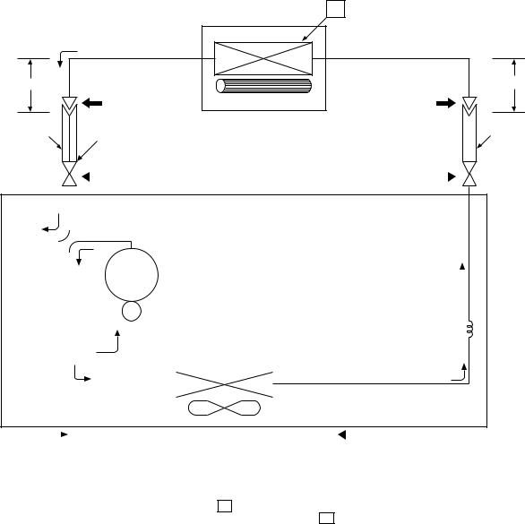
5. REFRIGERATION CYCLE DIAGRAM
5-1. RAS-13UKP-ES / RAS-13UA-ES
T1
Indoor unit
Heat exchanger
Cooling
0.39m (Connecting pipe)
9.52
Cross flow fan
0.49m (Connecting pipe)6.35
|
|
|
|
|
|
|
|
|
|
|
|
|
|
|
|
|
|
|
|
|
|
|
|
|
|
O.D.:9.52mm |
|
P |
|
|
|
|
|
|
|
|
|
|
|
|
|
|
O.D.:6.35mm |
||||||||
|
|
|
|
|
|
Packed valve |
|
|
|
|
|
|
Packed valve |
|
|
|
|||||||||
|
|
|
|
|
|
|
|
|
|
|
|
|
|
|
|||||||||||
|
|
|
|
|
|
|
( 9.52) |
|
|
|
|
|
|
|
( |
6.35) |
|
|
|
|
|
|
|||
|
|
|
|
|
|
|
|
|
|
|
|
|
|
|
|
|
|
|
|
||||||
|
|
|
|
|
|
|
|
|
|
|
|
|
|
|
|
|
|
|
|
||||||
|
|
|
|
|
|
|
|
|
|
|
|
|
|
|
|
|
|
|
|
|
|
|
|
||
Cooling |
|
|
|
|
|
|
|
|
|
|
|
|
|
|
|
|
|
|
|
|
|
||||
|
|
|
|
|
Cooling Compressor |
PA150X2T-4FM |
|
|
|
|
|
|
|
|
|
|
|
|
|
||||||
|
|
|
|
|
|
|
|
|
|
|
|
|
|
|
|
|
|
||||||||
|
|
|
|
|
|
|
|
|
|
|
|
|
|
|
|
|
|
||||||||
|
|
|
|
|
|
|
|
|
|
|
|
|
|
|
|
|
|
||||||||
|
|
|
|
|
|
|
|
|
|
|
|
|
|
|
|
|
|
||||||||
|
|
|
|
|
|
|
|
|
|
|
|
|
|
|
|
|
|
Capillary tube |
|
|
|
||||
|
|
|
|
|
|
|
|
|
|
|
|
|
|
|
|
|
|
|
1.5x900S |
|
|
|
|||
|
|
|
|
|
|
|
|
|
|
|
|
Condenser |
|
|
|
|
|
|
|
|
|
|
|
|
|
|
|
|
|
|
|
|
|
|
|
|
|
|
|
|
|
|
|
|
|
|
|
|
|
|
|
|
|
|
|
|
|
|
|
|
|
|
|
|
|
|
|
|
Refrigerant |
|
|
|
|||||
|
|
|
|
|
|
|
|
|
|
|
|
|
|
|
|
|
|
|
|
||||||
|
|
|
|
|
|
|
|
|
|
|
|
|
|
|
|
|
|
|
|
||||||
|
|
|
|
|
|
|
|
|
|
|
|
Propeller fan |
|
|
|
|
R-22 : 0.86 kg. |
|
|
|
|||||
|
|
|
|
|
Cooling |
|
Outdoor unit |
|
Mark( |
|
)means check points of Gas Leak. |
|
|||||||||||||
|
|
|
|
|
|
|
|
|
|||||||||||||||||
|
|
|
|
|
|
|
|
|
|
|
|
|
|
|
|
|
|
|
|
|
|
|
|
|
|
|
|
|
|
|
|
|
|
|
|
|
Standard |
Surface temp. of heat |
|
|
|
|
|
|
|
Ambient temp. |
|||||
|
|
|
|
|
|
|
|
|
|
|
|
Fan speed |
|
conditions DB/WB |
|||||||||||
|
|
50Hz |
|
|
|
|
|
pressure P |
exchanger interchanging |
|
|||||||||||||||
|
|
|
|
|
|
|
(indoor) |
|
|
(°C) |
|||||||||||||||
|
|
|
|
|
|
|
|
|
|
|
|
(MPaG) |
|
pipe T1 (°C) |
|
|
|
|
|||||||
|
|
|
|
|
|
|
|
|
|
|
|
|
|
|
|
|
|
|
|
|
Indoor |
Outdoor |
|||
|
|
|
|
|
|
|
|
|
|
|
|
|
|
|
|
|
|
|
|
|
|
|
|
||
|
|
|
|
|
|
|
|
|
|
|
|
|
|
|
|
|
|
|
|
|
|
|
|
|
|
|
Standard |
|
|
|
|
|
0.95 |
10.0 |
|
|
|
|
High |
|
27/19 |
35/24 |
|||||||||
|
|
|
|
|
|
|
|
|
|
|
|
|
|
|
|
|
|
|
|
|
|
|
|
|
|
Cooling |
Overload |
|
|
|
|
|
1.15 |
13.0 |
|
|
|
|
High |
|
32/23 |
43/26 |
|||||||||
|
|
|
|
|
|
|
|
|
|
|
|
|
|
|
|
|
|
|
|
|
|
|
|
|
|
|
Low temperature |
|
0.65 |
2.0 |
|
|
|
|
Low |
|
21/15 |
21/15 |
|||||||||||||
|
|
|
|
|
|
|
|
|
|
|
|
|
|
|
|
|
|
|
|
|
|
|
|
|
|
Note :
• Measure the heat exchanger temperature at the center of U-bend. (By means of TC sensor)
– 12 –
FILE NO. SVM-02005(1)
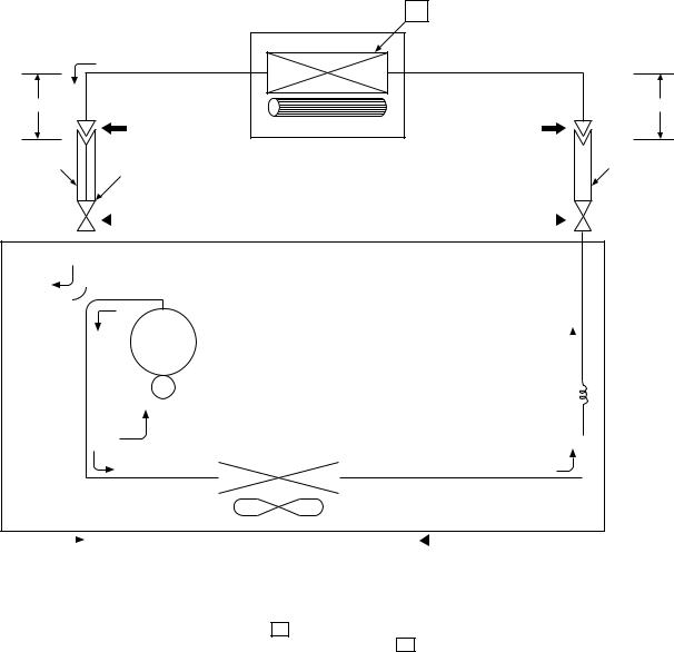
5-2. RAS-10UKP-ES / RAS-10UA-ES
T1
|
Indoor unit |
|
Evaporator |
|
Cooling |
0.39m |
|
(Connecting pipe) |
|
|
9.52 |
|
Cross flow fan |
0.49m (Connecting pipe)6.35
|
|
|
|
|
|
|
|
|
|
|
|
|
|
|
|
|
|
|
|
|
|
|
|
|
|
O.D.:9.52mm |
|
P |
|
|
|
|
|
|
|
|
|
|
|
|
|
|
O.D.:6.35mm |
||||||||
|
|
|
|
|
|
Packed valve |
|
|
|
|
|
|
|
Packed valve |
|
|
|
||||||||
|
|
|
|
|
|
|
|
|
|
|
|
|
|
|
|
||||||||||
|
|
|
|
|
|
|
( 9.52) |
|
|
|
|
|
|
|
|
( |
6.35) |
|
|
|
|
|
|||
|
|
|
|
|
|
|
|
|
|
|
|
|
|
|
|
|
|
|
|
||||||
|
|
|
|
|
|
|
|
|
|
|
|
|
|
|
|
|
|
|
|
||||||
|
|
|
|
|
|
|
|
|
|
|
|
|
|
|
|
|
|
|
|
|
|
|
|||
Cooling |
|
|
|
|
|
|
|
|
|
|
|
|
|
|
|
|
|
|
|
|
|
||||
|
|
|
|
|
Cooling Compressor |
PA98X1T-4FZ |
|
|
|
|
|
|
|
|
|
|
|
|
|
||||||
|
|
|
|
|
|
|
|
|
|
|
|
|
|
|
|
|
|
||||||||
|
|
|
|
|
|
|
|
|
|
|
|
|
|
|
|
|
|
||||||||
|
|
|
|
|
|
|
|
|
|
|
|
|
|
|
|
|
|
||||||||
|
|
|
|
|
|
|
|
|
|
|
|
|
|
|
|
|
|
|
Capillary tube |
|
|
|
|||
|
|
|
|
|
|
|
|
|
|
|
|
|
|
|
|
|
|
|
|
1.5x1200S |
|
|
|
||
|
|
|
|
|
|
|
|
|
|
|
|
Condenser |
|
|
|
|
|
|
|
|
|
|
|
|
|
|
|
|
|
|
|
|
|
|
|
|
|
|
|
|
|
|
|
|
|
|
|
|
|
|
|
|
|
|
|
|
|
|
|
|
|
|
|
|
|
|
|
|
|
|
|
|
|
|
|
|
|
|
|
|
|
|
|
|
|
|
|
|
|
|
|
|
|
|
|
Refrigerant |
|
|
|
||||
|
|
|
|
|
|
|
|
|
|
|
|
|
|
|
|
|
|
|
|
|
|||||
|
|
|
|
|
|
|
|
|
|
|
|
|
|
|
|
|
|
|
|
|
|||||
|
|
|
|
|
|
|
|
|
|
|
|
Propeller fan |
|
|
|
|
|
R-22 : 0.65 kg. |
|
|
|
||||
|
|
|
|
|
Cooling |
|
Outdoor unit |
|
Mark( |
|
|
)means check points of Gas Leak. |
|
||||||||||||
|
|
|
|
|
|
|
|
|
|||||||||||||||||
|
|
|
|
|
|
|
|
|
|
|
|
|
|
|
|
|
|
|
|
|
|
|
|
|
|
|
|
|
|
|
|
|
|
|
|
|
Standard |
Surface temp. of heat |
|
|
|
|
|
|
Ambient temp. |
||||||
|
|
|
|
|
|
|
|
|
|
|
|
Fan speed |
conditions DB/WB |
||||||||||||
|
|
50Hz |
|
|
|
|
|
pressure P |
exchanger interchanging |
||||||||||||||||
|
|
|
|
|
|
|
(indoor) |
|
(°C) |
||||||||||||||||
|
|
|
|
|
|
|
|
|
|
|
|
(MPaG) |
|
pipe T1 (°C) |
|
|
|
||||||||
|
|
|
|
|
|
|
|
|
|
|
|
|
|
|
|
|
|
|
|
Indoor |
Outdoor |
||||
|
|
|
|
|
|
|
|
|
|
|
|
|
|
|
|
|
|
|
|
|
|
|
|||
|
|
|
|
|
|
|
|
|
|
|
|
|
|
|
|
|
|
|
|
|
|
|
|
||
|
|
|
|
|
|
|
|
|
|
|
|
|
|
|
|
|
|
|
|
|
|
|
|
|
|
|
Standard |
|
|
|
|
|
0.86 |
12.0 |
|
|
|
|
|
High |
27/19 |
35/24 |
|||||||||
|
|
|
|
|
|
|
|
|
|
|
|
|
|
|
|
|
|
|
|
|
|
|
|
|
|
Cooling |
Overload |
|
|
|
|
|
1.12 |
18.0 |
|
|
|
|
|
High |
32/23 |
43/26 |
|||||||||
|
|
|
|
|
|
|
|
|
|
|
|
|
|
|
|
|
|
|
|
|
|
|
|
|
|
|
Low temperature |
|
0.61 |
2.0 |
|
|
|
|
|
Low |
21/15 |
21/15 |
|||||||||||||
|
|
|
|
|
|
|
|
|
|
|
|
|
|
|
|
|
|
|
|
|
|
|
|
|
|
Note :
• Measure the heat exchanger temperature at the center of U-bend. (By means of TC sensor)
– 13 –

FILE NO. SVM-02005(1)
5-3. RAS-07UKP-ES / RAS-07UA-ES
T1
|
Indoor unit |
|
Evaporator |
|
Cooling |
0.39m |
|
(Connecting pipe) |
|
|
9.52 |
|
Cross flow fan |
0.49m (Connecting pipe)6.35
|
|
|
|
|
|
|
|
|
|
|
|
|
|
|
|
|
|
|
|
|
|
|
|
|
|
|
|
O.D.:9.52mm |
|
P |
|
|
|
|
|
|
|
|
|
|
|
|
|
|
|
|
O.D.:6.35mm |
||||||||
|
|
|
|
|
|
Packed valve |
|
|
|
|
|
|
|
Packed valve |
|
|
|
||||||||||
|
|
|
|
|
|
|
|
|
|
|
|
|
|
|
|
||||||||||||
|
|
|
|
|
|
|
( 9.52) |
|
|
|
|
|
|
|
|
( |
6.35) |
|
|
|
|
|
|
|
|||
|
|
|
|
|
|
|
|
|
|
|
|
|
|
|
|
|
|
|
|
|
|
||||||
|
|
|
|
|
|
|
|
|
|
|
|
|
|
|
|
|
|
|
|
|
|
||||||
|
|
|
|
|
|
|
|
|
|
|
|
|
|
|
|
|
|
|
|
|
|
|
|
|
|||
Cooling |
|
|
|
|
|
|
|
|
|
|
|
|
|
|
|
|
|
|
|
|
|
|
|
||||
|
|
|
|
|
Cooling Compressor |
PA79X1T-4FZ5 |
|
|
|
|
|
|
|
|
|
|
|
|
|
|
|
||||||
|
|
|
|
|
|
|
|
|
|
|
|
|
|
|
|
|
|
|
|
||||||||
|
|
|
|
|
|
|
|
|
|
|
|
|
|
|
|
|
|
|
|
||||||||
|
|
|
|
|
|
|
|
|
|
|
|
|
|
|
|
|
|
|
|
||||||||
|
|
|
|
|
|
|
|
|
|
|
|
|
|
|
|
|
|
|
Capillary tube |
|
|
|
|||||
|
|
|
|
|
|
|
|
|
|
|
|
|
|
|
|
|
|
|
|
1.2x650S |
|
|
|
||||
|
|
|
|
|
|
|
|
|
|
|
|
Condenser |
|
|
|
|
|
|
|
|
|
|
|
|
|
|
|
|
|
|
|
|
|
|
|
|
|
|
|
|
|
|
|
|
|
|
|
|
|
|
|
|
|
|
|
|
|
|
|
|
|
|
|
|
|
|
|
|
|
|
|
|
|
Refrigerant |
|
|
|
||||||
|
|
|
|
|
|
|
|
|
|
|
|
|
|
|
|
|
|
|
|
|
|||||||
|
|
|
|
|
|
|
|
|
|
|
|
Propeller fan |
|
|
|
|
|
R-22 : 0.65 kg. |
|
|
|
||||||
|
|
|
|
|
Cooling |
|
Outdoor unit |
|
Mark( |
|
|
)means check points of Gas Leak. |
|
||||||||||||||
|
|
|
|
|
|
|
|
|
|||||||||||||||||||
|
|
|
|
|
|
|
|
|
|
|
|
|
|
|
|
|
|
|
|
|
|
|
|
|
|
|
|
|
|
|
|
|
|
|
|
|
|
|
Standard |
Surface temp. of heat |
|
|
|
|
|
|
|
|
Ambient temp. |
||||||
|
|
|
|
|
|
|
|
|
|
|
|
Fan speed |
|
conditions DB/WB |
|||||||||||||
|
|
50Hz |
|
|
|
|
|
pressure P |
exchanger interchanging |
|
|||||||||||||||||
|
|
|
|
|
|
|
(indoor) |
|
|
(°C) |
|||||||||||||||||
|
|
|
|
|
|
|
|
|
|
|
|
(MPaG) |
|
pipe T1 (°C) |
|
|
|
|
|||||||||
|
|
|
|
|
|
|
|
|
|
|
|
|
|
|
|
|
|
|
|
|
|
Indoor |
Outdoor |
||||
|
|
|
|
|
|
|
|
|
|
|
|
|
|
|
|
|
|
|
|
|
|
|
|
|
|||
|
|
|
|
|
|
|
|
|
|
|
|
|
|
|
|
|
|
|
|
|
|
|
|
|
|
||
|
|
|
|
|
|
|
|
|
|
|
|
|
|
|
|
|
|
|
|
|
|
|
|
|
|
|
|
|
Standard |
|
|
|
|
|
0.97 |
14.0 |
|
|
|
|
|
High |
|
27/19 |
35/24 |
||||||||||
|
|
|
|
|
|
|
|
|
|
|
|
|
|
|
|
|
|
|
|
|
|
|
|
|
|
|
|
Cooling |
Overload |
|
|
|
|
|
1.13 |
20.0 |
|
|
|
|
|
High |
|
32/23 |
43/26 |
||||||||||
|
|
|
|
|
|
|
|
|
|
|
|
|
|
|
|
|
|
|
|
|
|
|
|
|
|
|
|
|
Low temperature |
|
0.63 |
2.0 |
|
|
|
|
|
Low |
|
21/15 |
21/15 |
||||||||||||||
|
|
|
|
|
|
|
|
|
|
|
|
|
|
|
|
|
|
|
|
|
|
|
|
|
|
|
|
Note :
• Measure the heat exchanger temperature at the center of U-bend. (By means of TC sensor)
– 14 –
FILE NO. SVM-02005(1)
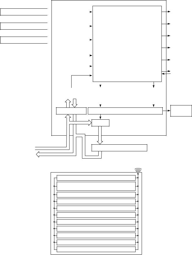
6. CONTROL BLOCK DIAGRAM
Heat Exchange sensor
Thermo. Sensor
Infrared Rays Signal Reciver
220-240 V~, 50Hz
REMOTE CONTROL
Main Unit Control Panel |
|
|
|
|
|
M.C.U. |
|
|
|
|
|||
|
|
|
|
|
|
Functions |
|
|
|
Operation |
|||
|
|
|
|
|
|
|
|
|
|||||
|
|
|
|
|
|
|
|
|
Display |
||||
|
|
|
|
|
|
|
|
||||||
|
|
|
|
|
|
|
|
|
|
|
|
|
|
|
|
|
|
|
|
|
|
|
|
|
|
|
|
|
|
|
|
|
|
|
|
|
|
|
|
|
|
|
|
|
|
|
|
• |
|
|
|
|
|
|
Timer |
|
|
|
|
|
|
Louver Control |
|
|
|
Display |
|||
|
|
|
|
|
|
|
|
||||||
|
|
|
|
|
|
|
|
|
|
|
|
|
|
|
|
|
|
|
|
|
|
|
|
|
|
|
Filter Sign |
|
|
|
|
|
|
• |
3-minutes Delay at Restart |
|
|
|
Display |
||
|
|
|
|
|
|
|
|
|
|||||
|
|
|
|
|
|
|
|
|
|
||||
|
|
|
|
|
|
|
|
|
|||||
|
|
|
|
|
|
|
|
||||||
|
|
|
|
|
|
|
for Compressor |
|
|
|
Hi Power |
||
|
|
|
|
|
|
|
|
|
|
|
|
|
|
|
|
|
|
|
|
|
|
|
|
|
|
|
Sign Display |
|
|
|
|
|
|
• |
|
|
|
|
|
|
|
|
Initiallizing Circuit |
|
|
Motor Revolution Control |
|
|
|
|
|||||
|
|
|
|
|
|
|
Fan Only |
||||||
|
|
|
|
|
|
|
|
|
|
|
|
|
|
|
|
|
|
|
|
|
|
|
|
|
|
|
|
|
|
|
|
|
|
|
|
|
|
|
|
|
Sign Display |
|
Clock Frequency |
|
|
|
• |
Processing |
|
|
|
||||
|
|
|
|
|
|
|
|
||||||
|
|
|
|
|
|
||||||||
|
Oscillator Circuit |
|
|
|
|
|
|
Indoor Fan |
|||||
|
|
|
|
|
(Temperature Processing) |
|
|
|
|||||
|
|
|
|
|
|
• |
|
|
|
||||
|
|
|
|
|
|
Timer |
|
|
|
Motor |
|||
|
|
|
|
|
|
|
|
|
|
||||
|
|
|
|
|
|
|
|
|
|
|
|
|
|
|
|
|
|
|
|
|
|
|
|
|
|
|
|
|
Power Supply |
|
|
Compressor |
|
Louver |
|
|
|||||
|
Circuit |
|
|
|
|
ON/OFF |
|
ON/OFF |
|
||||
|
|
|
|
|
|
Signal |
|
Signal |
|
||||
|
|
|
|
|
|
|
|
|
|||||
|
|
|
|
|
|
|
|
|
|
|
|
|
|
|
|
|
|
|
|
|
|
|
|
|
|
|
|
Noise Filter Relay Driver, Louver Driver
Louver
Motor
Relay
RY01
Compressor, Outdoor Fan Motor
Infrared Rays
Remote Control
Operation (START/STOP)
Operation Mode Selection
AUTO, COOL, DRY, FAN ONLY
Temperature Setting
Fan Speed Selection
ON TIMER Setting
OFF TIMER Setting
Louver Auto Swing
Louver Direction Setting
ECO
Hi power
Filter Reset
– 15 –
FILE NO. SVM-02005(1)
7. OPERATION DESCRIPTION
7-1. Outline of Air Conditioner Control
This is a fixed capacity type air conditioner, which uses a AC motor for an indoor fan. The AC motor drive circuit is mounted in the indoor unit. And electrical parts which operate the compressor and the outdoor fan motor, are mounted in the outdoor unit.
The air conditioner is mainly controlled by the indoor unit controller. The controller operates the indoor fan motor based upon commands transmitted by the remote control and transfers the operation commands to the outdoor unit controller.
The outdoor unit controller receives operation commands from the indoor unit, and operates the outdoor fan motor and the compressor.
(1)Role of indoor unit controller
The indoor unit controller receives the operation commands from the remote control and executes them.
•Temperature measurement at the air inlet of the indoor heat exchanger by the indoor temperature sensor
•Temperature setting of the indoor heat exchanger by the heat exchanger sensor
•Louver motor control
•Indoor fan motor operation control
•LED display control
•Transferring of operation commands to the outdoor unit
•Receiving of information of the operation status and judging of the information or indication of error
7-1-1. Louver control
(1)Vertical air flow louver
Position of veritcal air flow louver is automatically controlled according to the operation mode. Besides, position of vertical air flow louver can be arbitrarily set by pressing [FIX] button.
The louver position which is set by [FIX] button is stored in the microcontroller, and the louver is automatically set at the stored position for the next operation.
(2)Swing
If [SWING] button is pressed when the indoor unit is in operation, the vertical air flow louver starts swinging. When [FIX] button is pressed, it stops swinging.
7-1-2. Indoor fan control (AC fan motor)
(1)The indoor fan is operated by the stepless speed change AC motor.
(2)For air flow level, speed of the indoor fan motor is controlled in five steps (LOW, LOW+, MED, MED+ and HIGH). If AUTO mode is selected, the fan motor speed is automatically controlled by the difference between the preset temperature and the room temperature.
LOW+ = LOW+MED 2
MED+ = MED+HIGH 2
Table 7-1-1
|
|
|
RAS-13UKP-ES |
RAS-10UKP-ES |
RAS-07UKP-ES |
|||
|
|
|
|
|
|
|
|
|
|
Model |
Motor speed |
Air flow level |
Motor speed |
Air flow level |
Motor speed |
Air flow level |
|
|
|
|
(rpm) |
(m3/h) |
(rpm) |
(m3/h) |
(rpm) |
(m3/h) |
|
|
HIGH |
1,300 |
630 |
1,300 |
630 |
1,200 |
570 |
|
|
|
|
|
|
|
|
|
Cooling |
|
MED+ |
1,220 |
600 |
1,180 |
560 |
1,100 |
520 |
|
|
|
|
|
|
|
|
|
and |
|
MED |
1,150 |
550 |
1,050 |
490 |
1,000 |
460 |
|
|
|
|
|
|
|
|
|
Fan only |
|
LOW+ |
1,070 |
500 |
950 |
430 |
900 |
400 |
|
|
|
|
|
|
|
|
|
|
|
LOW |
1,000 |
460 |
850 |
370 |
800 |
340 |
|
|
|
|
|
|
|
|
|
– 16 –
7-2. Description of Operation Circuit
(1)When turning on the breaker, the operation lamp blinks. This means that the power is on (or the power supply is cut off.)
(2)When pressing [START / STOP] button on the remote control, receiving beep sounds from the indoor unit, and the next operation is performed together with opening the vertical air flow louver.
(3)Once the operation mode is set, it is memorized in the microcontroller so that the previous operation can be effected thereafter simply by pressing [START / STOP] button.
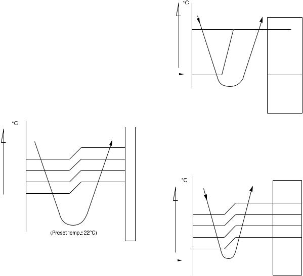
7-2-1. Fan only operation
([MODE] button on the remote control is set to the fan only operation.)
(1)When [FAN] button is set to AUTO, the indoor fan motor operates as shown in Fig. 7-2-1. When [FAN] button is set to LOW, LOW+, MED, MED+ or HIGH, the motor operates with a constant air flow.
temp.) |
+3 |
|
|
|
|||
(Preset |
M+ |
||
+2.5 |
|||
|
|||
|
|
||
|
|
||
|
*1 |
||
— |
+2 |
|
|
|
|||
temp.) |
*1 |
||
*1 |
|||
(Room |
+1.5 |
|
|
+0.5 |
|
||
|
+1 |
L- |
|
|
|
||
Preset 0 temp.
NOTE :
*1: The values marked with *1 are calculated and controlled by the difference in motor speed between M+ and L–.
Fig. 7-2-1 Setting of air flow [FAN:AUTO]
(2) The Hi POWER operation cannot be set.
FILE NO. SVM-02005(1)
7-2-2. Cooling operation
([MODE] button on the remote control is set to the cooling operation.)
(1)The compressor, outdoor fan and operation display on the remote control are controlled as shown in Fig. 7-2-2.
temp.) |
|
|
|
|
|
|
(Preset |
0.5 |
ON |
|
ON |
|
|
|
|
|||||
|
|
|
||||
temp.) — |
|
|
|
|
||
|
|
OFF |
|
OFF |
ON |
|
(Room |
|
|
|
|||
|
|
|
|
|
|
|
Preset |
|
0 |
|
|
|
|
|
|
|
|
|
||
temp. |
|
|
Compressor |
|
Outdoor fan |
OPERATION display |
|
|
|
|
|||
|
|
|
|
|
|
|
Fig. 7-2-2
(2)When [FAN] button is set to AUTO, the indoor fan motor operates as shown in Fig. 7-2-3. When [FAN] button is set to LOW, LOW+, MED, MED+ or HIGH, the motor operates with a constant air flow.
temp.) |
+3 |
||
(Preset |
|
M+ |
|
*1 |
|||
|
+2.5 |
||
— |
+2 |
||
*1 |
|||
temp.) |
|||
+1.5 |
|||
|
|||
|
*1 |
||
(Room |
+1 |
||
|
L- |
||
|
+0.5 |
||
Preset |
|
0 |
|
|
|||
temp. |
-0.5 |
||
|
|||
NOTE :
*1: The values marked with *1 are calculated and controlled by the difference in motor speed between M+ and L–.
Fig. 7-2-3 Setting of air flow [FAN:AUTO]
– 17 –
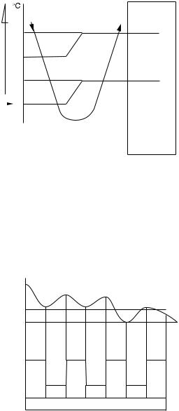
7-2-3. Dry operation
([MODE] button on the remote control is set to the dry operation.)
(1)The compressor, outdoor fan and operation display on the remote control are controlled as shown in Fig. 7-2-4.
(Preset—temp.)temp.) |
+3 |
ON:5min.ON:6min. OFF:5min.OFF:4min. |
|
ON:5min.ON:6min. OFF:5min.OFF:4min. |
|
|
|
|
|||||
|
|
|
|
|
||
(Room |
+2 |
|
|
|
ON |
|
+1 |
|
|
|
|
||
|
|
|
|
|
||
|
|
|
OFF |
|
OFF |
|
Preset |
|
0 |
|
|
|
|
|
Compressor |
|
fanOutdoor |
OPERATION display |
||
temp. |
|
|
|
|||
|
|
|
|
|
|
|
|
|
|
|
|
|
|
Fig. 7-2-4
(2)The microcontroller turns the compressor on and off at the regular intervals (4 to 6 minutes). While the compressor is turning off, the indoor fan motor operates in the SUPER LOW position.
The pattern of operation depending on the relation between room temperature and preset temperatures is shown in Fig. 7-2-5.
Room temp.
Preset temp.+1
Preset temp.
Compressor |
ON |
ON |
|
ON |
|
ON |
|
|
|
|
|
|
|
|
|
Outdoor fan |
|
OFF |
|
OFF |
OFF |
||
|
|
|
|||||
Indoor fan |
|
|
|
|
|
|
|
L. |
*S.L. |
L. |
S.L. |
L. |
S.L. |
L. |
|
|
*Super Low |
|
|
|
|
|
|
Fig. 7-2-5
(3)[FAN] button on the remote control is set to AUTO only.
(4)The Hi POWER operations cannot be set.
FILE NO. SVM-02005(1)
7-2-4. Automatic operation
([MODE] button on the remote control is set to the automatic operation.)
(1)One of 2 operations (Cooling, Fan only) is selected according to difference between the preset temperature and the room temperature at which the automatic operation has started, as shown in Fig. 7-2-6. The Fan only operation continues until the room temperature reaches a level at which another mode is selected.
(2)Temporary Auto
When the TEMPORARY button on the indoor unit is pushed, the preset temperature is fixed at 24°C and the indoor unit is controlled as shown in
Fig. 7-2-6.
|
°C |
Cooling operation |
|
temp.) |
|
The louver moves to the position same |
|
+4 |
as Hi POWER operation. |
||
|
|||
|
|
||
(Preset– |
Cooling operation |
||
|
|||
|
|
||
|
0 |
|
|
(Roomtemp.) |
Fan only operation |
||
|
|||
|
|
||
|
RAS-13UKP-ES |
||
|
|
||
|
|
RAS-10UKP-ES |
|
|
|
RAS-07UKP-ES |
|
|
|
|
|
|
|
Fig. 7-2-6 |
– 18 –
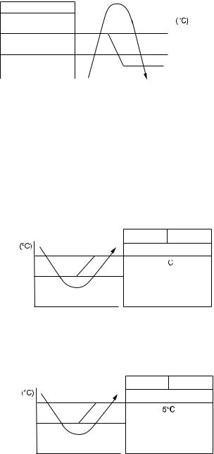
7-3. Hi POWER Mode
([Hi POWER] button on the remote control is pressed.)
When [Hi POWER] button is pressed while the indoor unit is in Auto, Cooling, Hi POWER mark is indicated on the display of the remote control and the unit operates as follows.
(1)Automatic operation
•The indoor unit operates in according to the current operation.
(2)Cooling operation
•The preset temperature drops 3°C.
(The value of the preset temperature on the remote control does not change.)
•If the difference between the preset temperature and the room temperature is big, the horizontal louver moves to the Hi POWER position automatically. Then when the difference between them gets smaller, the horizontal louver returns automatically.
•FAN speed : [AUTO]
If the difference between the preset temperature and room temperature is big, the air conditioner operates at maximum airflow level. If the difference between the preset temperature and the room temperature is small, the air conditioner operates at normal airflow level.
•FAN speed : One of 5 levels
The air conditioner operates at normal airflow level.
(3)The Hi POWER mode can not be set in Dry or Fan only operation.
FILE NO. SVM-02005(1)
7-4. High-Temperature Limit Control
The microcontroller detects the indoor heat exchanger temperature to prevent pressure of a refrigerating cycle from increasing excessively.
The compressor and outdoor fan motor are controlled as shown in Fig. 7-4-1.
Compressor |
|
Outdoor fan |
|
Heat exchanger |
|
||||
|
|
temp. |
||
|
|
|
|
|
OFF |
|
OFF |
|
60 |
|
|
|
|
|
ON |
|
OFF |
|
53 |
|
|
|
|
|
ON |
|
ON |
|
52 |
|
|
|
||
|
|
|
|
|
Fig. 7-4-1
7-5. Low-Temperature Limit Control
The microcontroller detects the indoor heat exchanger temperature to prevent the indoor heat exchanger from freezing.
The compressor and outdoor fan motor are controlled as shown in Fig. 7-5-1 and 7-5-2.
RAS-13UKP-ES
Heat exchanger |
|
temperature |
Compressor Outdoor fan |
|
ON |
6
Less than  continues
2
for 5 minutes OFF
|
Fig. 7-5-1 |
|
RAS-10UKP-ES |
;RAS-07UKP-ES |
|
Heat exchanger |
|
|
temperature |
Compressor Outdoor fan |
|
|
||
7 |
ON |
|
Less than continues |
||
|
||
5 |
for 5 minutes |
|
OFF |
||
|
Fig. 7-5-2
– 19 –
 Loading...