


Toshiba HWS-1402XWHT6-E, HWS-1402XWHM3-E, HWS-802XWHM3-E, HWS-802XWHT6-E, HWS-1402XWHT9-E INSTALLATION MANUAL
AIR TO WATER HEAT PUMP
Installation manual
Hydro Unit
Model name:
HWS-802XWHM3-E
HWS-802XWHT6-E
HWS-1402XWHM3-E
HWS-1402XWHT6-E
HWS-1402XWHT9-E
Installation manual |
|
English |
Hydro Unit (Air to Water Heat Pump) |
2 |
|
|
|
|
Manuel d’installation |
|
|
|
|
|
Unité hydroélectrique |
44 |
Français |
(Pompe à chaleur air/eau) |
||
Installations-handbuch |
|
|
|
|
|
Hydrogerät |
86 |
Deutsch |
(Luft-Wasser-Wärmepumpe) |
||
Installationshandbok |
|
|
|
|
|
Hydroenhet |
128 |
Svenska |
(Luft-till-vatten-värmepump) |

Hydro Unit |
Installation Manual |
Please read this Installation Manual carefully before installing the Air to Water Heat Pump.
•This Manual describes the installation method of the hydro unit.
•For installation of the outdoor unit, follow the Installation Manual attached to the outdoor unit.
ADOPTION OF NEW REFRIGERANT
This Air to Water Heat Pump is a new type which adopts a new refrigerant HFC (R410A) instead of the conventional refrigerant R22 in order to prevent destruction of the ozone layer.
Contents |
|
|
1 |
GENERAL INFORMATION . . . . . . . . . . . . . . . . . . . . . . . . . . . . . . . . . . . . . . . . . . . . . |
. 3 |
2 |
ACCESSORY PARTS . . . . . . . . . . . . . . . . . . . . . . . . . . . . . . . . . . . . . . . . . . . . . . . . . . |
4 |
3 |
PREPARATIONS FOR INSTALLATION . . . . . . . . . . . . . . . . . . . . . . . . . . . . . . . . . . . . |
4 |
4 |
PRECAUTIONS FOR SAFETY . . . . . . . . . . . . . . . . . . . . . . . . . . . . . . . . . . . . . . . . . . . |
5 |
5 |
EXAMPLE OF HYDRO UNIT INSTALLATION . . . . . . . . . . . . . . . . . . . . . . . . . . . . . . . |
7 |
6 |
MAIN COMPONENTS OF HYDRO UNIT . . . . . . . . . . . . . . . . . . . . . . . . . . . . . . . . . . . |
9 |
7 |
HYDRO UNIT INSTALLATION . . . . . . . . . . . . . . . . . . . . . . . . . . . . . . . . . . . . . . . . . . |
11 |
8 |
START UP AND CONFIGURATION . . . . . . . . . . . . . . . . . . . . . . . . . . . . . . . . . . . . . . |
31 |
9 |
TEST RUN . . . . . . . . . . . . . . . . . . . . . . . . . . . . . . . . . . . . . . . . . . . . . . . . . . . . . . . . . . |
38 |
10 MAINTENANCE . . . . . . . . . . . . . . . . . . . . . . . . . . . . . . . . . . . . . . . . . . . . . . . . . . . . . . |
39 |
|
11 SENSOR TEMPERATURE MONITORING FUNCTION . . . . . . . . . . . . . . . . . . . . . . . |
39 |
|
12 TROUBLESHOOTING . . . . . . . . . . . . . . . . . . . . . . . . . . . . . . . . . . . . . . . . . . . . . . . . . |
40 |
|
1-EN |
– 2 – |

Hydro Unit |
Installation Manual |
1 GENERAL INFORMATION
Hydro Unit Description
Hydro Unit |
|
Model Description |
|
|
|
HWS-802XWHM3-E |
8 kW Hydro Unit (3 kW 230 V ~ back up heater) |
|
|
|
|
HWS-802XWHT6-E |
8 kW Hydro Unit (6 kW 400 V 3N ~ back up heater) |
|
|
|
|
HWS-1402XWHM3-E |
11 |
& 14 kW Hydro Unit (3 kW 230 V ~ back up heater) |
|
|
|
HWS-1402XWHT6-E |
11 |
& 14 kW Hydro Unit (6 kW 400 V 3N ~ back up heater) |
|
|
|
HWS-1402XWHT9-E |
11 |
& 14 kW Hydro Unit (9 kW 400 V 3N ~ back up heater) |
|
|
|
General Specifications
|
Outdoor unit |
|
HWS-802H-E |
HWS-1102H-E |
HWS-1402H-E |
|
Type |
|
|
|
|
Inverter |
|
|
|
|
|
|
|
|
Function |
|
|
|
|
Heating & Cooling |
|
|
|
|
|
|
|
|
|
|
Capacity |
(kW) |
8.0 |
11.2 |
14.0 |
|
|
|
|
|
|
|
Heating |
|
Input |
(kW) |
1.96 |
2.40 |
3.15 |
|
|
|
|
|
|
|
|
|
COP |
|
4.08 |
4.66 |
4.45 |
|
|
|
|
|
|
|
|
|
Capacity |
(kW) |
6.0 |
10.0 |
11.0 |
|
|
|
|
|
|
|
Cooling |
|
Input |
(kW) |
2.13 |
3.52 |
4.08 |
|
|
|
|
|
|
|
|
|
EER |
|
2.82 |
2.84 |
2.69 |
|
|
|
|
|
|
|
Power supply |
|
|
230 V ~ |
|
||
|
|
|
|
|
|
|
Refrigerant |
|
|
|
|
R410A |
|
|
|
|
|
|
|
|
Dimension |
|
HxWxD |
(mm) |
890 x 900 x 320 |
1,340 x 900 x 320 |
|
|
|
|
|
|
|
|
Hydro Unit |
|
HWS- |
HWS- |
|
HWS- |
|
|
HWS- |
HWS- |
|
|||
|
802XWHM3-E |
802XWHT6-E |
1402XWHM3-E |
1402XWHT6-E |
1402XWHT9-E |
|
|
||||||
|
|
|
|
||||||||||
|
|
|
|
|
|
|
|
|
|
|
|
||
Back up heater capacity |
|
3 kW |
6 kW |
|
3 kW |
|
|
6 kW |
9 kW |
|
|
||
|
|
|
|
|
|
|
|
|
|
|
|
||
|
for backup heater |
230 V ~ |
400 V 3N ~ |
230 V ~ |
|
400 V 3N ~ |
400 V 3N ~ |
|
|
||||
Power supply |
|
|
|
|
|
|
|
|
|
|
|
|
|
for hot water cylinder |
|
|
|
|
230 V ~ |
|
|
|
|
|
|||
|
heater(option) |
|
|
|
|
|
|
|
|
|
|
||
|
|
|
|
|
|
|
|
|
|
|
|
|
|
Leaving water |
Heating |
(°C) |
|
|
|
|
20 to 55 |
|
|
|
|
|
|
temperature |
Cooling |
(°C) |
|
|
|
|
10 to 25 |
|
|
|
|
|
|
|
|
|
|
|
|
|
|
|
|
||||
|
|
|
|
|
|
|
|
|
|
|
|
||
For use with |
|
|
HWS-802H-E |
|
HWS-1102H-E/HWS-1402H-E |
|
|||||||
|
|
|
|
|
|
|
|
|
|
|
|
|
|
Dimension |
HxWxD |
(mm) |
|
|
|
|
925 x 525 x 355 |
|
|
|
|
|
|
|
|
|
|
|
|
|
|
EN |
|||||
|
|
|
|
|
|
|
|
|
|
|
|
|
|
|
|
|
|
|
|
|
|
|
|
|
|
|
|
Hot water cylinder (option) |
HWS-1501CSHM3-E |
|
HWS-2101CSHM3-E |
|
HWS-3001CSHM3-E |
|
|
||||||
HWS-1501CSHM3-UK |
|
HWS-2101CSHM3-UK |
HWS-3001CSHM3-UK |
|
|
||||||||
|
|
|
|
|
|||||||||
Water volume |
|
litres |
150 |
|
|
|
210 |
|
|
|
300 |
|
|
|
|
|
|
|
|
|
|
|
|
|
|
|
|
Max water temperature |
(°C) |
|
|
|
|
75 |
|
|
|
|
|
|
|
|
|
|
|
|
|
|
|
|
|
|
|
|
|
Electric heater |
|
(kW) |
|
|
|
|
2.75 (230 V ~) |
|
|
|
|
|
|
|
|
|
|
|
|
|
|
|
|
|
|
|
|
Height |
|
(mm) |
1,090 |
|
|
|
1,474 |
|
|
|
2,040 |
|
|
|
|
|
|
|
|
|
|
|
|
|
|
|
|
Diameter |
|
(mm) |
|
|
|
|
550 |
|
|
|
|
|
|
|
|
|
|
|
|
|
|
|
|
|
|
|
|
Material |
|
|
|
|
|
|
Stainless steel |
|
|
|
|
|
|
|
|
|
|
|
|
|
|
|
|
|
|
|
|
– 3 – |
2-EN |

Hydro Unit Installation Manual
2 |
ACCESSORY PARTS |
|
|
|||
No |
Parts name |
Quantity |
|
No |
Parts name |
Quantity |
|
|
|
|
|
|
|
1 |
Installation manual (this document) |
1 |
|
3 |
Insulator for cooling |
1 |
|
|
|
|
|
|
|
2 |
Owner’s manual |
1 |
|
|
|
|
|
|
|
|
|
|
|
3 PREPARATIONS FOR INSTALLATION
Parts required to connect this product (Common items)
Category |
Part |
Specification |
Quantity |
|
|
|
|
|
Strainer (water filter) |
1 1/4" 30 to 40 meshes |
1 |
|
|
|
|
Water piping |
Drain cock |
(for water charge) |
1 |
|
|
|
|
|
Isolating ball valves |
1 1/4" |
2 |
|
for service 1 1/4" |
||
|
|
|
|
|
Earth leakage breaker for main power |
30 mA |
1 |
|
supply |
||
|
|
|
|
Electrical system |
Earth leakage breaker for backup heater |
30 mA |
1 |
|
|
|
|
|
(Option) |
30 mA |
1 |
|
Earth leakage breaker for hot water cylinder |
||
|
heater |
|
|
Options required for each function
Purpose |
In the Hydro Unit |
|
Purchased part |
|
||
|
|
|
|
|
||
Part name |
Model name |
Part name |
Prescribed specification |
|||
|
||||||
|
|
|
|
|
|
|
Heating |
|
– |
– |
Radiator(s), Fan coil(s), |
|
|
|
Under floor heating |
|
||||
|
|
|
|
|
||
Heating &Cooling |
|
– |
– |
Fan coil(s) |
|
|
(all rooms) |
|
|
||||
|
|
|
|
|
||
Heating & Cooling |
|
– |
– |
Motorized 2-way valve (for |
Refer to “Control parts |
|
(partly heating only) |
|
cooling) |
specifications” on page 23. |
|||
|
|
|
||||
|
Hot water cylinder |
|
|
|
||
|
|
|
|
|
|
|
|
|
150 L |
HWS-1501CSHM3-E |
|
|
|
|
|
|
|
|
||
|
|
HWS-1501CSHM3-UK |
Motorized 3-way valve |
Refer to “Control parts |
||
|
|
|
||||
Hot water supply |
|
|
|
|||
|
|
HWS-2101CSHM3-E |
||||
|
210 L |
Earth leakage breaker |
specifications” on page 23. |
|||
|
|
|
||||
|
|
HWS-2101CSHM3-UK |
||||
|
|
|
|
|
||
|
|
|
|
|
|
|
|
|
300 L |
HWS-3001CSHM3-E |
|
|
|
|
|
|
|
|
||
|
|
HWS-3001CSHM3-UK |
|
|
||
|
|
|
|
|
||
|
|
|
|
|
|
|
|
|
|
|
Motorized mixing valve |
Refer to “Control parts |
|
|
|
|
|
specifications” on page 23. |
||
2-zone control |
|
– |
– |
|
||
|
Circulator pump |
Other power supply |
||||
|
|
|
|
|||
|
|
|
|
|
|
|
|
|
|
|
Buffer tank |
|
|
|
|
|
|
|
|
|
Interlocking with |
Output control |
|
|
Other power supply |
||
TBC-PCIN3E |
Boiler |
Signal 12 V input function is |
||||
boiler |
board kit (1) |
|||||
|
|
required for boiler. |
||||
|
|
|
|
|
||
|
|
|
|
|
|
|
Interlocking with |
Output control |
|
|
Other power supply. |
||
TBC-PCIN3E |
Electric heater |
Signal 230 V input function |
||||
booster heater |
board kit (1) |
is required for booster |
||||
|
|
|||||
|
|
|
|
|
heater |
|
|
|
|
|
|
|
|
3-EN |
– 4 – |

Hydro Unit Installation Manual
Optional Parts
No. |
Part name |
Model name |
Application |
Remarks |
|
|
|
|
|
|
|
|
External output |
|
Boiler-linked output, Alarm output |
Up to two boards |
|
1 |
TCB-PCIN3E |
|
|||
Defrost signal output, compressor operation |
|||||
board |
(according to applications) |
||||
|
|
||||
|
|
|
signal output |
|
|
2 |
External input |
TCB-PCMO3E |
Cooling/heating thermostat input |
Up to two boards |
|
|
|||||
board |
Forced-stop signal input |
(according to applications) |
|||
|
|
||||
|
|
|
|
||
|
|
|
|
|
Use specified products for the outdoor unit, Hydro Unit, and hot water cylinder. Do not use commercially available products.
Use parts that conform to prescribed specifications for parts to be connected to the Hydro Unit. If unspecified products or parts are used, a malfunction, failure or fire may be caused.
4 PRECAUTIONS FOR SAFETY
General Safety Precautions
Ensure that all Local, National and International regulations are satisfied.
•Read the “PRECAUTIONS FOR SAFETY” carefully before installation.
•The precautions described below include the important items regarding safety – Observe them without fail.
•After the installation work has been completed, perform a trial operation to check for any problems. Follow the Owner’s Manual to explain how to use and maintain the unit to the customer.
•Turn off the main power supply switch (or breaker) before unit maintenance.
•Ask the customer to keep the Installation Manual along with the Owner’s Manual.
Refrigerant Precautions
•If a refrigerant leak is suspected contact the dealer who supplied the system, in the case of a recharge of refrigerant ask service personnel for details of the leak and confirmation of the repairs completed.
The refrigerant used in the system is harmless.
•Generally the refrigerant does not leak, however, if the refrigerant should leak into a room and a heater or stove burner in the room is lit, toxic gas may be generated.
•Do not install the system in a location subject to a risk of exposure to a combustible gas. If a combustible gas leaks and stays around the unit a fire may occur.
•Install the refrigerant pipe securely during installation and before operation.
If the compressor is operated with no pipe work connected and valves open the compressor will suck air which
would result in over pressurization of the system which may result in bursting or injury. |
|
Observe the same precautions for refrigerant recovery work (pump back procedure to outdoor unit) and do not |
|
disconnect pipe work until refrigerant is recovered and valves closed. |
EN |
– 5 – |
4-EN |

Hydro Unit |
Installation Manual |
 WARNING
Installation Precautions
•Ask an authorized dealer or qualified installation professional to install/maintain the Air to Water Heat Pump System. Inappropriate installation may result in water leaks, electric shock or fire.
•Electrical work must be performed by a qualified electrician in accordance with the installation manual. An inappropriate power supply capacity or installation may result in fire.
•When completing any electrical works to the system ensure that all Local, National and International regulations are satisfied.
Inappropriate grounding may result in electric shock.
•Use the specified electrical cables, fixing securely at all terminations.
•Earth wire connections.
•Install an earth leakage breaker without fail. Incomplete grounding can cause electric shock.
Do not ground wires to gas pipes, water pipes, lightning rods or telephone cable ground wires.
•This unit must be connected to the main power supply using a circuit breaker or switch with a contact separation of at least 3 mm.
•Be sure to turn off all main power supply switches or the circuit breaker before starting any electrical work. Ensure all power switches are off, failure to do so can cause electric shock.
Use an exclusive power circuit for the Air to Water Heat Pump system using the rated voltage.
•Ensure correct connection of interconnecting wire between Outdoor Unit and Hydro Unit. Incorrect connection of the interconnecting cable may result in the damage of electrical parts.
•Ensure refrigeration system remains sealed to external gases and air.
Should air or other gases contaminate the refrigeration circuit, high system pressures could result in burst pipes and injuries.
•Do not modify or bypass any of safety guards or switches in this system.
•After unpacking the outdoor unit, examine the unit carefully for any possible damage.
•Do not install in any place that might increase the vibration of the unit.
•To avoid personal injury (with sharp edges), be careful when handling parts.
•Perform installation work properly in accordance with the installation manual. Inappropriate installation may result in water leaks, electric shock or fire.
•Tighten all flare nuts with a torque wrench in the specified manner.
Excessive tightening of the flare nut may result in cracking of the pipe work or flare nut which may result in a refrigerant leakage.
•Wear heavy duty gloves during installation work to avoid injury.
•Install the outdoor unit securely in a location where the base can sustain the weight adequately.
•In enclosed areas, if the refrigerant leaks during installation vacate and ventilate immediately.
•After installation is complete ensure and confirm that refrigerant does not leak.
If refrigerant leaks into a room and flows near a fire source noxious gas may be generated.
•Do not block any drain hoses. Hoses may come off and electric shocks may occur.
•Do not hit the manometer, because it is made of glass. It is breakable.
Notes on System Design
•The input water temperature to the Hydro Unit must be 55°C or less. Especially, be careful when there is an external heating source such as a boiler.
When hot water over 55°C returns, it may result in a failure of the unit or water leakage.
•The flow rate of the circulating water must meet the following range. 11 and 14 kW 18 L/minute or more
8 kW 13 L/minute or more
If the flow rate becomes less than the minimum, the protective device is activated to stop operation. Ensure the flow rate with a bypass valve, etc. when you use a flow rate valve for the Hydro Unit.
•Do not drive water by power other than the pump built in the Hydro Unit.
•The backup heater operates supplementarily to exert a prescribed capacity when the heat pump cannot exert its capacity at a low outside temperature.
•Install the Hydro Unit and water pipes in a place in which they do not freeze.
•Make the water circuit closed. Never use it as an open circuit.
•Circulating water must be 20 liters or more. If total water amount is not enough, the unit may not function fully due to protective operation.
5-EN |
– 6 – |
Hydro Unit |
Installation Manual |
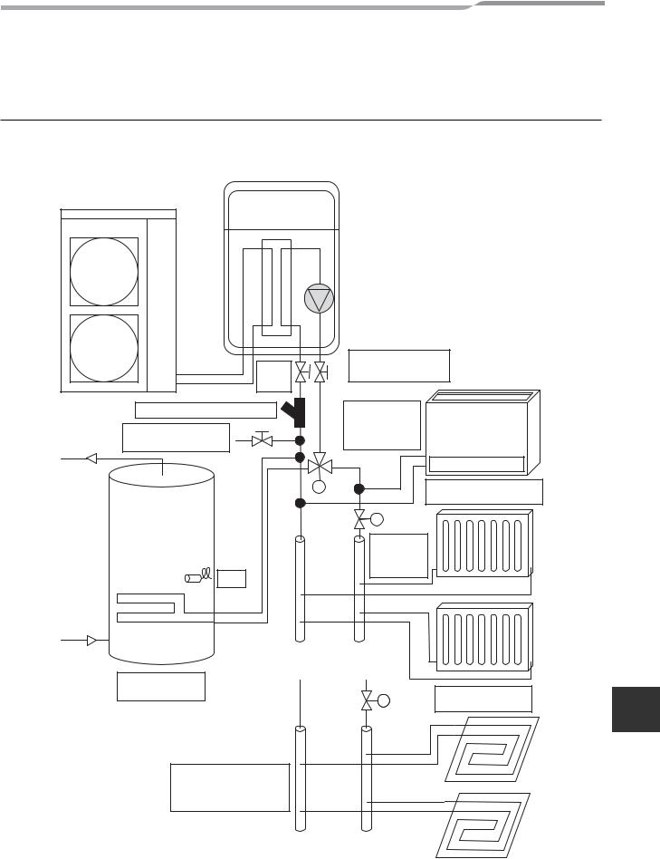
5 EXAMPLE OF HYDRO UNIT INSTALLATION
Example of Installation for Cooling and Heating
When both cooling and heating are used, install a 2-way valve (for cooling) to the pipe to the room for heating only.
▼Fig. 5-01
|
Fan Coil Units |
|
Isolating |
(Cooling or Heating) |
|
Ball |
|
|
Valves |
|
|
Strainer (40 mesh / 0.4 mm) |
Diverting 3-Way |
|
|
Valve for |
|
Drain Cock for water |
Sanitary Hot |
|
Charge and Drain |
Water Tank |
|
M |
|
Radiators (Heating Only) |
|
|
[2-Way Valve Control] |
|
M |
2-Way |
|
Valve |
|
|
Use it when |
|
|
do not |
|
|
operate |
|
TTW |
cooling. |
|
|
|
|
Indirect Sanitary |
|
|
|
Hot Water Tank |
2-Way |
Use it when do not |
|
M |
|||
Valve |
operate cooling. |
Alternative to Radiators
Under-floor Heating (Heating Only) [2-Way Valve Control]
EN
– 7 – |
6-EN |
Hydro Unit |
Installation Manual |
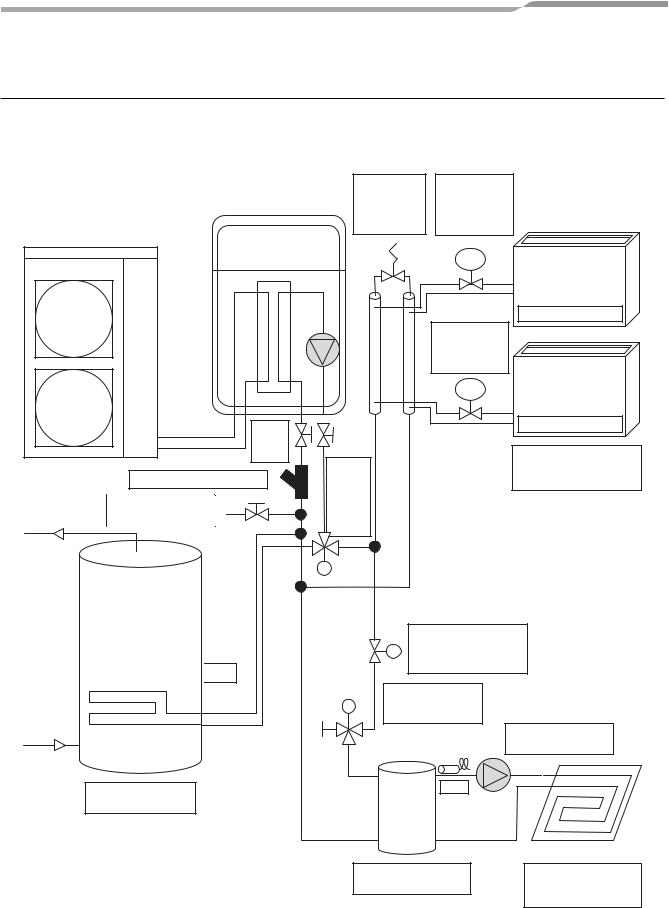
Example of 2-Zone Temperature Control and Hot Water Supply System
The following shows an example of the 2-zone temperature control.
A buffer tank and a water pump are required for the 2-zone temperature control.
▼Fig. 5-02
Isolating Valves (Service)
Strainer (40 mesh / 0.4 mm)
Drain Cock for water
Charge and Drain

 TTW
TTW
Hi-Pressure |
Temperature |
By-Pass |
Regulating |
Valve |
Valve |
|
(Mechanical) |
TRV
Temp. Regulating Valve (Mechanical)
TRV
|
Zone 1 |
Diverting |
Fan Coil Unit (Heating |
3-Way |
or Cooling) |
Valve for |
|
Sanitary |
|
Hot |
|
Water |
|
Tank |
|
M
Motorized 2-Way Valve is required if fan coil
Munits are in cooling operation.
Indirect Sanitary Hot
Water Tank
Mixing 3-Way
MValve for Under Floor Heating
External Pump for
Under Floor Heating
TFI
Direct Buffer tank for Under Floor Heating
Zone 2
Under-floor Heating
(2-Way Valve Control)
7-EN |
– 8 – |
Hydro Unit |
Installation Manual |
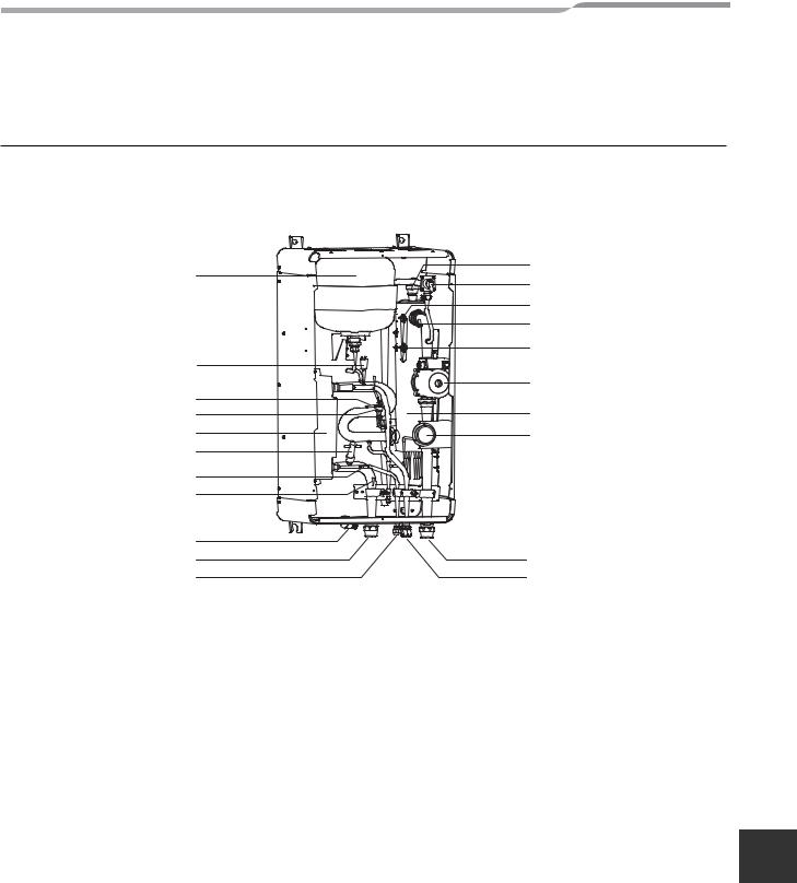
6 MAIN COMPONENTS OF HYDRO UNIT
Exploded view and description for Hydro Unit
▼Fig. 6-01
1
2
3
4
5
6
7
8
9
10
11
1 : Expansion vessel
2 : Hi pressure switch (4.15 MPa)
3 : Temperature sensor (for Heat pump outlet -TWO) 4 : Pressure sensor
5 : Heat exchanger
6 : Flow switch (13.0 L/min 17.5 L/min)
7 : Temperature sensor (for refrigerant -TC)
8 : Temperature sensor (for water inlet -TWI)
9 : Drain nipple
10 : Water inlet connection
11 : Refrigerant liquid connection
12 : Air relief valve
13 : Pressure relief valve (0.3 MPa (3 bar))
14 : Thermal protector (auto)
15 : Temperature sensor (for water outlet THO)
16 : Thermal protector (Single operation)
17 : Water pump
18 : Backup heater (3 kW, 3 kW x 2, 3 kW x 3) 19 : Manometer
20 : Water outlet connection
21 : Refrigerant gas connection
12
13
14
15
16
17
18
19
20
21
EN
– 9 – |
8-EN |
Hydro Unit |
Installation Manual |
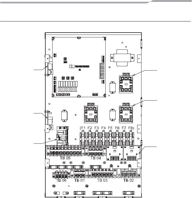
E-Box layout
▼Fig. 6-02
P.C. board
MCC-1511
|
Trans |
|
|
former |
|
Relay P.C. board |
MG-SW (RY04) |
|
MCC-1217 |
||
Relay |
||
(Option) |
||
(RY03) |
||
|
MG-SW (RY05) |
Relay |
MG-SW (RY02) |
Relay |
|
|
(RY06) |
(RY01) |
|
Relay P.C. board |
|
|
MCC-1217 |
|
|
(Option) |
Fuse |
|
|
|
Relay P.C. board |
Relay P.C. board |
MCC-1431 |
|
|
MCC-1214 |
|
(Option) |
9-EN |
– 10 – |
Hydro Unit |
Installation Manual |
7 HYDRO UNIT INSTALLATION
 WARNING
•To protect yourself from injury, always use PPE (Personal Protective Equipment), that is, wear gloves.
•Install the Hydro Unit by at least two persons.
•Install the Hydro Unit in a place strong enough to withstand the following weights: Hydro Unit weight with no water 60 kg (802) 65 kg (1402)
Hydro Unit weight with full water 80 kg (802) 85 kg (1402)
 CAUTION
• The operating temperature range is 5 to 32°C (Heating) and 18 to 30°C (Cooling). Do not install the unit in a place where water freezes.
• Do not install the Hydro Unit in a place where combustible gas may leak.
• Do not install the Hydro Unit in a place exposed to rain or water.
• Do not install the Hydro Unit near equipment which generates heat.
• Do not install the Hydro Unit to a movable object.
• Do not install the Hydro Unit in a place exposed to vibration.
Handling, Unpacking, and Checking the Hydro Unit
• The unit should be checked when it is delivered, and any damage reported immediately to the courier claims the department.
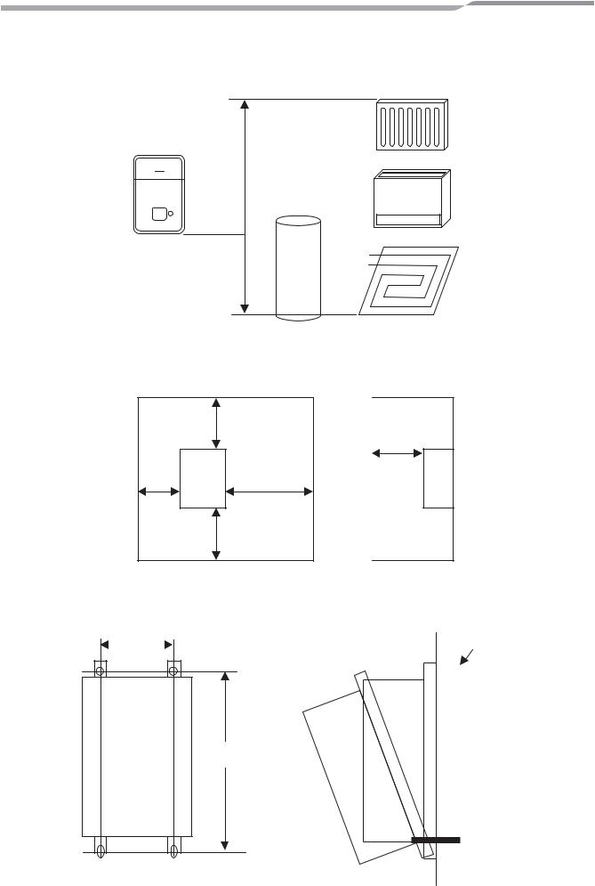
Positioning
Refrigeration pipe
The length and height of the refrigeration pipe must be within the following values.
As long as the Hydro Unit is installed within these ranges, no additional refrigerant is required.
▼Fig. 7-01
Outdoor unit
L |
H |
EN
H: Max. ±30 m (above or below)
L:Max. 30 m
Min. HWS-802H-E : 5 m HWS-1102H-E : 3 m HWS-1402H-E : 3 m
– 11 – |
10-EN |
Hydro Unit |
Installation Manual |
Water pipe
Design the water pipe length within the QH characteristics of the pump (Refe to “Fig. 7-16” and “Fig. 7-17” on page 19). The height of the pipe must be 7 m or less.
▼Fig. 7-02
H < 7 m
Service space
Secure a service space for the Hydro Unit.
• Do not install the Hydro Unit in a place where heat stagnates.
▼Fig. 7-03 |
|
200 mm |
|
100 mm |
350 mm |
|
|
500 mm |
|
500 mm |
Mounting
Install M10 bolts at the positions shown below and secure them with nuts.
▼Fig. 7-04 |
380 mm |
|
|
|
M10 |
|
|
|
|
|
|
|
|
|
|
|
|
|
|
|
|
|
|
960 mm
11-EN |
|
|
|
– 12 – |
|
|
|
Hydro Unit |
Installation Manual |
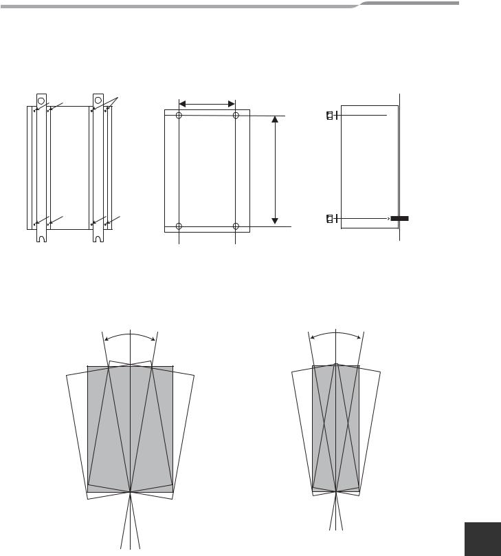
The Hydro Unit can be installed directly without using the fixing angles.
However, the back side of the Hydro Unit can be highly heated, therefore, the installing surface must be heatresistant.
▼Fig. 7-05 |
▼Fig. 7-06 |
▼Fig. 7-07 |
380

 M10
M10
860
M10
Remove the M5a screws to detach the fixing angles.
Install the Hydro Unit so that its tilting angle falls within the range below.
▼Fig. 7-08 |
▼Fig. 7-09 |
± 1° |
Secure the Hydro Unit with plain washers and nuts.
± 1° |
EN
– 13 – |
12-EN |

Hydro Unit |
Installation Manual |
Refrigerant Piping
 WARNING
•THIS SYSTEM ADOPTS HFC REFRIGERANT (R410A) WHICH DOES NOT DESTROY THE OZONE LAYER.
•The characteristics of R410A refrigerant are: ease to absorb water, oxidizing membrane or oil, and its pressure is approximately 1.6 times higher that of R22. Accompanied with the new refrigerant the oil has also been changed. Therefore during installation work prevention of the invasion of water, dust, former refrigerant or oil is of a paramount importance.
To prevent the charging of incorrect refrigerants into the system the service valve connection ports have also increased in size.
•The use of R410A tools is required for correct installation of the system.
•The use of the correct pipe sizes and wall thicknesses of copper pipe work is required for the correct installation of the system.
 CAUTION
•Ensure all refrigerant pipes are protected from the invasion of dust and water.
•Ensure all pipe work connections are tightened to the required torque settings detailed in this section.
•Perform an air tight using Oxygen Free Nitrogen (OFN) only.
•Evacuate the air in the pipe work using a vacuum pump.
•Check for refrigerant gas leaks at all connections throughout the pipe work.
NOTE
The Air to Water Heat Pump system uses R410A refrigerant. It is important that copper pipes used for refrigerant piping have the following wall thickness:
•0.8 mm for Ø6.4 mm, Ø9.5 mm and Ø12.7 mm
•1.0 mm for Ø15.9 mm
Refrigerant pipe sizes
Hydro Unit Model |
Gas Side (mm) |
Liquid Side (mm) |
|
|
|
8 kW Hydro Unit |
Ø 15.88 |
Ø 9.52 |
|
|
|
11 & 14 kW Hydro Unit |
Ø 15.88 |
Ø 9.52 |
|
|
|
Flaring
•Cut the refrigerant pipes to the correct length using a pipe cutter. Remove any burrs that may be on the pipes as these may cause refrigerant leaks or component failure in the refrigeration cycle.
•Place the correct size flare nuts onto the pipes (use the flare nuts supplied with the Hydro Unit or use flare nuts designed specifically for R410A refrigerant) and then flare the pipes using the correct flaring tool.
13-EN |
– 14 – |
Hydro Unit |
Installation Manual |
Tightening
• Connect the refrigerant pipes, from the outdoor unit, to the Hydro Unit as shown below.
▼Fig. 7-10
Gas line Ø 15.88
Liquid line Ø 9.52
• Align the flare connection on each pipe with the corresponding outlet connection on the Hydro Unit. Tighten the flare nuts, using fingers, to secure the pipes in place.
• Tighten the flare nuts, using a torque wrench, to the tightening torques shown below:
Outer Ø of Copper Pipe (mm) |
Tightening Torque (N/m) |
|
|
9.5 |
33 to 42 |
|
|
15.9 |
63 to 77 |
|
|
• To prevent damage, to the refrigerant pipes, use two spanners to tighten the flare nut connections to the required torque.
Water Pipe
 WARNING
•Install water pipes according to the regulations of respective countries.
•Install water pipes in a freeze-free place.
•Make sure that water pipes have sufficient pressure resistance. The setting value of the pressure relief valve is 0.3 MPa.
 CAUTION
•Do not use zinc plated water pipes. When steel pipes are used, insulate both ends of the pipes.
•The water to be used must meet the water quality standard specified in EN directive 98/83 EC.
EN
– 15 – |
14-EN |
Hydro Unit |
Installation Manual |
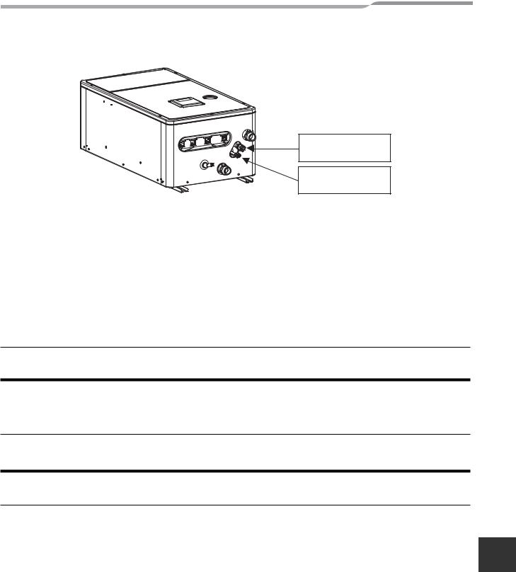
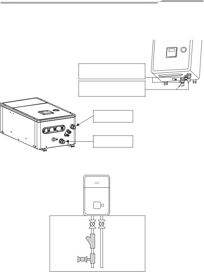
Water circuit
•Install a strainer with 30 to 40 meshes (procured locally) at the water inlet of the Hydro Unit.
•Install drain cocks (procured locally) for water charge and discharge at the lower part of the Hydro Unit.
•Make the piping route a closed circuit. (An open water circuit may cause a failure.)
▼Fig. 7-11
Attention
To avoid water leak, exchange the seal tapes to new one.
Attention
Water (used at test in factory before shipping) may be found in the caps.
Hot water outlet connection 1 1/4"
Water inlet connection 1 1/4"
▼Fig. 7-12
Inlet
Isolating Ball Valve
Strainer (30 to 40 meshes)
Drain cock for water charge and discharge
Local arrangement
15-EN |
– 16 – |
Hydro Unit |
Installation Manual |
Piping to hot water tank (option)
Water supplied to the hot water cylinder is branched by a motorized 3-way valve (procured locally). For the specifications of the motorized 3-way valve, refer to “Control parts specifications” on page 23. Connect the hot water cylinder to port A (open when energized) of the valve.
▼Fig. 7-13 |
to hydro unit |
room heating or cooling |
|
AB to hot water cylinder |
||||
|
||||||
|
|
|
|
|
|
|
|
B |
|
|
|
A |
|
Open when de-energized |
|
|
|
Open when energized |
||
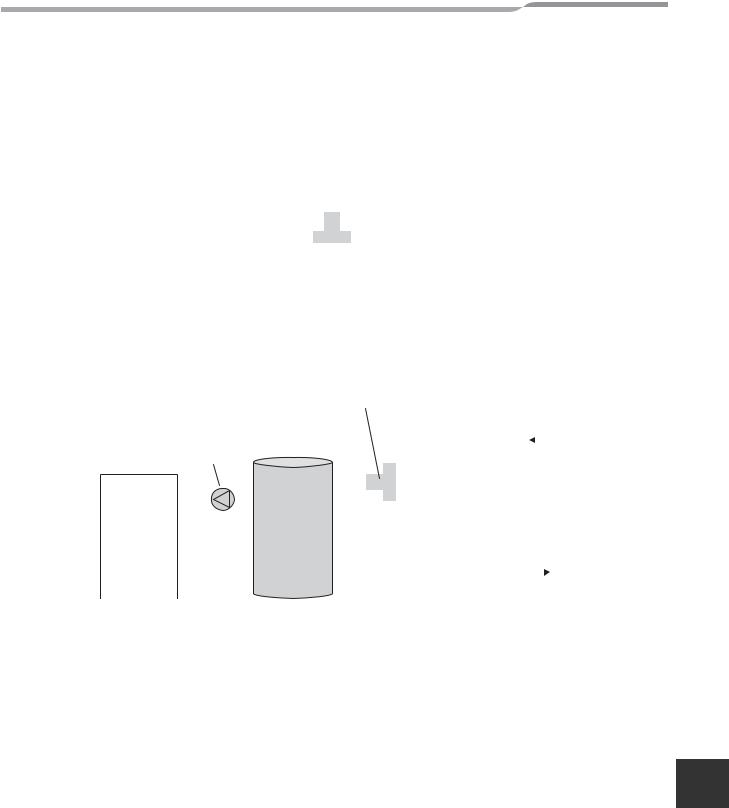
Piping to 2-zone operation
To perform 2-zone temperature control, circulate water by another pump (procured locally) through a motorized mixing valve (procured locally) and a buffer tank (procured locally).
For the specifications of the motorized mixing valve, Refer to “Control parts specifications” on page 23.
▼Fig. 7-14 |
Motorized mixing valve |
|
A |
|||||||||||||
|
|
|
|
|
(Procured locally) |
|
||||||||||
|
|
|
|
|
|
Open when |
||||||||||
|
|
|
|
|
|
|
|
|
|
|||||||
|
Water pump |
|
|
|
|
|
energized |
|||||||||
|
|
|
|
|
|
|
|
|
|
|
|
to hydro unit |
||||
|
|
|
|
|
|
|
||||||||||
|
|
|
|
|
|
|
|
|
|
|
|
|||||
|
(Procured locally) |
|
|
AB |
|
|
|
|
|
|
|
|
||||
|
|
|
|
|
|
|
|
|
|
|
|
|
|
|
||
|
Zone 2 |
|
|
|
|
|
|
|
|
|
|
|
|
|
||
|
|
|
|
|
|
|
|
|
|
|
|
|||||
|
|
|
|
|
|
|
|
|
|
|
|
|
|
|
|
|
|
|
|
|
|
|
|
|
|
|
B |
||||||
|
|
|
|
|
|
|
|
|
|
Open when |
||||||
|
|
|
|
|
|
|
|
|
|
de-energized |
||||||
|
|
|
|
|
|
|
|
|
|
|
|
|
|
|
|
Buffer tank |
|
|
|
|
|
|
|
|
|
|
|
|
|||||
|
|
|
|
|
|
|
|
|
|
|
|
|
|
|
|
(Procured locally) |
|
|
|
|
|
|
|
|
|
|
|
|
|||||
|
|
|
|
|
|
|
|
|
|
|
|
|
|
|
|
|
Checking water volume and initial pressure of expansion vessel
The expansion vessel of the Hydro Unit has a capacity of 12 liters. The initial pressure of the expansion vessel is 0.1 MPa (1 bar). The pressure of the safety valve is 0.3 MPa (3 bar).
Verify whether the capacity of the expansion vessel is sufficient using the following expression. If the volume is insufficient, add the capacity locally.
EN
– 17 – |
16-EN |
Hydro Unit |
Installation Manual |
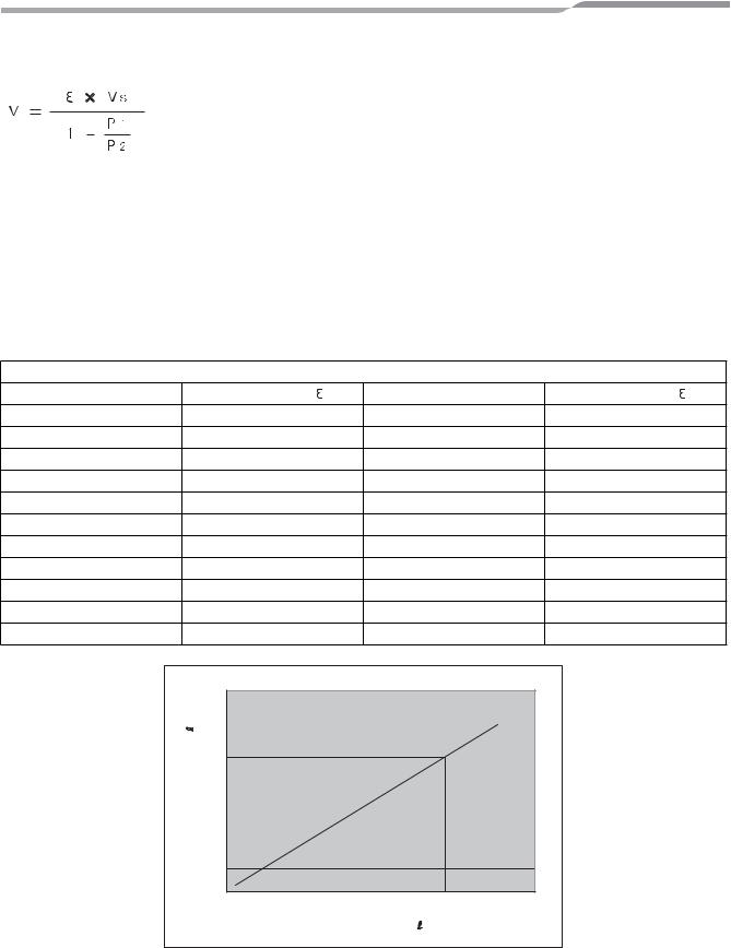
Expression for expansion vessel selection
V:Necessary total tank capacity ( )
)
 : Water expansion coefficient at average hot water temperature Vs: Total water amount in the system
P1: System pressure at tank setting position (MPaabs.)
(Pipe inner pressure during pump operation before heating device operates = water supply pressure) P2: Maximum pressure used during operation at tank setting position (MPaabs.)
(= safety valve setting pressure)
*The absolute pressure value (abs.) is obtained by adding the atmospheric pressure (0.1 MPa (1 bar)) to the gauge pressure.
▼Tank selection method |
|
|
|
|
|
|
|
|
|
|
|
Water temperature and expansion coefficient |
|
|
|||||
Hot water temperature (°C) |
|
Expansion rate |
|
Hot water temperature (°C) |
Expansion rate |
||||
0 |
0.0002 |
|
|
50 |
|
|
|
0.0121 |
|
4 |
0.0000 |
|
|
55 |
|
|
|
0.0145 |
|
5 |
0.0000 |
|
|
60 |
|
|
|
0.0171 |
|
10 |
0.0003 |
|
|
65 |
|
|
|
0.0198 |
|
15 |
0.0008 |
|
|
70 |
|
|
|
0.0229 |
|
20 |
0.0017 |
|
|
75 |
|
|
|
0.0258 |
|
25 |
0.0029 |
|
|
80 |
|
|
|
0.0292 |
|
30 |
0.0043 |
|
|
85 |
|
|
|
0.0324 |
|
35 |
0.0050 |
|
|
90 |
|
|
|
0.0961 |
|
40 |
0.0078 |
|
|
95 |
|
|
|
0.0967 |
|
45 |
0.0100 |
|
|
|
|
|
|
|
|
▼Fig. 7-15 |
|
|
|
|
|
|
|
|
|
|
|
18 |
|
|
|
|
|
|
|
|
) |
16 |
|
|
|
|
|
|
|
|
volume( |
14 |
|
|
|
|
|
|
|
|
|
|
|
|
|
|
|
|
|
|
|
12 |
|
|
|
|
|
|
|
|
vessel |
10 |
|
|
|
|
|
|
|
|
8 |
|
|
|
|
|
|
|
|
|
|
|
|
|
|
|
|
|
|
|
Expansion |
6 |
|
|
|
|
|
|
|
|
4 |
|
|
|
|
|
|
|
|
|
|
|
|
|
|
|
|
|
|
|
|
2 |
|
|
|
|
|
|
|
|
|
0 |
|
|
|
200 |
250 |
300 |
|
|
|
0 |
50 |
100 |
150 |
|
|||
|
|
|
|
Water volume ( |
) |
|
|
|
|
*Hot water temperature 55ºC
Install an external expansion vessel when the capacity of the expansion vessel is insufficient.
17-EN |
– 18 – |
Hydro Unit |
Installation Manual |
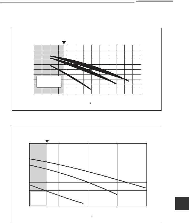
Pump operation/configuration
▼Fig. 7-16
Hydraulic heat exchanger (14 kW) QH characteristics
Minimum flow rate
|
10 |
|
|
|
|
|
|
|
|
|
|
|
|
|
|
9 |
|
|
|
|
|
|
|
|
|
|
|
|
|
|
8 |
|
|
|
|
|
|
|
|
|
|
|
|
|
(m) |
7 |
|
|
|
|
|
|
|
|
|
|
|
|
|
6 |
|
|
|
|
|
|
|
|
|
|
|
|
|
|
head |
|
|
|
|
|
|
|
|
|
|
|
|
|
|
5 |
|
|
|
|
|
|
|
|
|
|
|
|
|
|
Pump |
4 |
|
|
|
|
|
|
|
|
|
|
SW3 |
|
|
3 |
Out of Operation |
|
|
|
|
SW2 |
|
|
||||||
|
|
|
|
|
|
|
|
|
||||||
|
2 |
Range |
|
|
|
|
|
|
|
|
|
|
||
|
|
|
|
SW1 |
|
|
|
|
|
|
|
|||
|
|
|
|
|
|
|
|
|
|
|
|
|||
|
1 |
|
|
|
|
|
|
|
|
|
|
|
||
|
|
|
|
|
|
|
|
|
|
|
|
|
|
|
|
0 |
|
|
|
|
|
|
|
|
|
|
|
|
|
|
0 |
5 |
10 |
15 |
20 |
25 |
30 |
35 |
40 |
45 |
50 |
55 |
60 |
65 |
Flow rate ( /min)
/min)
▼Fig. 7-17
Hydraulic heat exchanger (8 kW) QH characteristics
Minimum flow rate
|
8 |
|
|
|
|
|
7 |
|
|
|
|
|
6 |
|
|
|
|
(m) |
5 |
|
|
|
|
head |
4 |
|
|
|
|
Pump |
3 |
|
|
|
SW 3 |
|
|
|
|
||
|
2 |
|
|
|
|
|
|
|
SW 2 |
|
|
|
|
Out of |
|
|
|
|
1 |
Operation |
|
|
|
|
|
Range |
SW 1 |
|
|
|
|
|
|
|
|
|
0 |
|
|
|
|
|
10 |
15 |
20 |
25 |
30 |
Flow rate ( /min)
/min)
EN
– 19 – |
18-EN |
Hydro Unit |
Installation Manual |
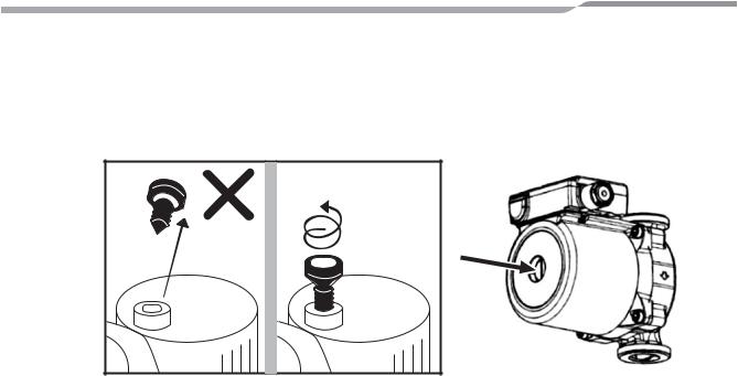
Water charging
Charge water until the pressure gauge shows 0.2 MPa (2 bar).
Hydraulic pressure may drop when the trial run begins. In that case, add water.
Air may enter if the charged hydraulic pressure is low.
Loosen the purge valve cap by two turns to release air.
▼Fig. 7-18 |
Loosen 2 turns for |
|
proper venting |
Loosen the air vent screw of the pump, pull out air in the pump, and tighten again. Loosen the cap of the pressure relief valve to release air.
Water may come out of the pressure relief valve.
Release the air completely from the water circuit. Failure to do so may disable correct operation.
Water quality
The water used must satisfy EN directive 98/83 EC.
Piping insulation
It is recommended that insulation treatment be applied to all pipes. To perform optional cooling operation, apply insulation treatment of 20 t or more to all pipes.
19-EN |
– 20 – |
Hydro Unit |
Installation Manual |
Electrical Installation
 WARNING
•Ensure electrical circuits are isolated before commencing the electrical installation.
•The electrical installation must be completed by a qualified electrician.
•The electrical installation must comply to all Local, National and International electrical installation regulations.
•This product must be earthed in accordance with Local, National and International electrical installation regulations.
 CAUTION
•The Hydro Unit must be connected to a dedicated power supply for the back up heater circuit.
•The electrical supply must be protected by a suitably sized over current protection device (fuse, MCB etc) and an earth leakage protection device.
•The Hydro Unit must be connected to the mains power supply using a isolating switch which disconnects all poles and has a contact separation of at least 3 mm.
•The cord clamps, attached to the Hydro Unit, must be used to secure the electrical cables.
•Wrong connection of electrical cables may result in electrical component failure or fire.
•Ensure the electrical cables are sized in accordance with the installation instructions.
Power line
▼Fig. 7-19
Backup heater
230 V ~ (3 kW type)
Input power 230 V ~ 50 Hz
Leakage breaker 30 mA
L N
TB02
|
|
1 |
1 |
TB01 |
|
|
2 |
2 |
|
|
|
|
||
Input power |
Leakage |
3 |
3 |
|
230 V ~ |
breaker |
L |
|
|
50 Hz |
30 mA |
N |
|
|
|
|
|
|
Backup heater
400 V 3N ~ (6.9 kW type)
Input power 400 V 3N ~ 50 Hz
Leakage breaker 30 mA
L1 L2 L3 N
TB02
TB03 |
1 |
|
2 |
|
|
|
|
|
|
|
Leakage |
|
L |
breaker |
|
N |
30 mA |
|
|
Hot water cylinder
1
2
Input power for cylinder heater 230 V ~ 50 Hz
EN
Outdoor unit |
Hydro unit |
– 21 – |
20-EN |

Hydro Unit |
Installation Manual |
Control line
▼Fig. 7-20
Pump (local)
Max 12 m
230 V 1 A
0.75 mm² or more
2Way-Valve for Max 12 m cooling stop
230 V 100 mA
0.75 mm² or more
Booster heater
(local) Max 12 m 230 V 1 A
0.75 mm² or more
3Way-Valve for hot water cylinder
Alert output (local)
Mixing-Valve |
Mixing-Valve type |
type 2 for 2 |
1 for 2 zone control |
zone control |
|
|
Max 12 m |
|
230 V 100 mA |
|
0.75 mm² or more |
1 |
2 |
3 |
4 |
CW |
N |
CCW |
Max 5 m shield wire |
|
TB04 |
|
|||||
|
|
0.75 mm² or more |
|||||
|
|
|
1 |
2 |
3 |
4 |
|
Temp sensor in hot water cylinder
|
|
|
TB04 |
|
|
A |
A |
||
1 |
|
|
|
|
|
|
|
B |
B |
2 |
TB05 |
|
|
|
|
TB06 |
|
|
|
4 |
|
|
|
|
D |
wire 0.75 mm² or |
|||
3 |
|
|
|
|
|
|
|
C |
Max 5 m shield |
|
|
|
|
|
|
|
|
|
|
5 |
|
|
|
|
|
|
|
|
more |
|
|
|
|
|
|
|
Temp sensor |
||
6 |
|
|
|
|
|
|
|
for 2 zone |
|
7 |
|
|
|
|
|
|
|
control |
|
|
|
|
|
|
|
|
|
|
|
8 |
CN208 |
|
|
CN209 |
|
|
|
||
9 |
OPTION |
|
OPTION |
|
|
|
|||
|
PJ20 |
|
|
PJ20 |
|
|
|
||
1 |
2 |
3 |
4 |
1 |
2 |
3 |
|
4 |
Max 12 m |
|
|
|
|
|
|
|
|
|
|
|
|
|
|
|
|
|
|
|
non voltage |
|
|
|
|
|
|
|
|
|
0.75 mm² or more |
Boiler operation |
|
Defrost output |
Compressor |
||||||
(local) |
|
|
|
|
(local) |
operation output |
|||
|
|
|
|
|
|
|
|
|
(local) |
▼Fig. 7-21
TB03
TB01
51 |
52 |
53 |
54 |
55 |
56 |
57 |
58 |
59 |
|
41 |
42 |
43 |
44 |
|
|
|
|
|
|
|
WPM |
2WV |
|
BH |
|
3WV |
|
|
|
MIXV |
|
|
|
|
|
|
|
|
|||
|
|
TB 05 |
|
|
|
|
|
|
|
|
TB 04 |
|
|
|
|
|
TB02 |
|
||
|
|
|
|
|
|
|
|
|
|
|
|
|
|
|
|
|
|
|
||
|
|
|
|
|
|
|
1 |
2 |
3 |
|
|
|
L1 |
L2 |
L3 |
N |
L1 |
L2 |
L3 |
N |
6A 6B 6C 6D |
Don't apply |
11 |
12 13 |
31 32 |
L N |
L |
N |
|
220-240V |
||||||||
TTW |
TF1 |
or |
|
|
HOT WATER CYLINDER |
|
|
|
TB 06 |
breakdown |
|
TB 01 |
|
TB 03 |
|
TB 02 |
|
will occur. |
|
|
|
|||||
|
to Outdoor unit |
Hot |
Input |
Input |
Input |
|
|
water |
power |
power |
power |
|
|
cylinder |
230 V ~ |
230 V ~ |
400 V 3N ~ |
|
|
|
50 Hz |
50 Hz |
50 Hz |
Sensor |
Outdoor unit |
Hot water |
Backup heater |
||
connection |
connection |
cylinder power |
power supply |
|
|
|
|
supply |
|
|
|
21-EN |
– 22 – |

Hydro Unit Installation Manual
Electrical supply/cable specifications
▼Wiring specifications
Description |
|
POWER SUPPLY |
Maximum |
Installation fuse |
Power wire |
|
Connection |
|
|
||||||||||
|
|
|
current |
rating |
|
|
destination |
|
|
||||||||||
Outdoor unit |
14 kW |
230 V ~ 50 Hz |
22.8 A |
25 A |
2.5 mm² or more |
|
|
|
|
|
|
|
|
|
|
|
|
|
|
|
|
|
|
|
|
|
|
|
|
|
|
|
|
|
|
|
|
|
|
11 kW |
230 V ~ 50 Hz |
22.8 A |
25 A |
2.5 mm² or more |
|
|
|
, |
|
|
|
|
|
|
|
|
|||
|
|
|
|
|
|
|
|
|
|
|
|||||||||
power |
|
|
|
|
|
|
|
|
|
|
|
||||||||
|
|
|
|
|
|
|
|
|
|
|
|
|
|
|
|
|
|
|
|
|
8 kW |
230 V ~ 50 Hz |
20.8 A |
25 A |
2.5 mm² or more |
|
|
|
|
|
|
|
|
|
|
|
|
|
|
|
|
|
|
|
|
|
|
|
|
|
|
|
|
|
|
|
|
|
|
Outdoor-Hydro |
|
– |
|
|
– |
1.5 mm² or more |
|
|
|
, |
|
|
, |
|
|
|
|
|
|
|
|
|
|
|
|
|
|
|
|
||||||||||
|
|
|
|
|
|
|
|
|
|
|
|
|
|
|
|
|
|
|
|
Hydro inlet heater |
3 kW |
230 V ~ 50 Hz |
13 A |
16 A |
1.5 mm² or more |
|
|
|
, |
|
|
(TB02) |
|||||||
|
|
|
|
|
|
|
|
|
|
|
|
|
|
|
|
|
|
|
|
6 kW |
400 V 3N ~ 50 Hz |
13 |
A (13 A x 2P) |
16 A |
1.5 mm² or more |
|
|
, |
|
|
, |
|
|
|
, |
||||
|
|
|
|
|
|||||||||||||||
power |
|
|
|
|
|
|
|
|
|
|
|
|
|
|
|
|
|
|
|
|
9 kW |
400 V 3N ~ 50 Hz |
13 A (13 A x 3P) |
16 A |
1.5 mm² or more |
|
|
|
|
(TB02) |
|
|
|||||||
|
|
|
|
|
|
|
|
|
|
|
|
|
|
|
|
|
|
|
|
Hydro cylinder heater power |
230 V ~ 50 Hz |
12 |
A |
16 A |
1.5 mm² or more |
|
|
, |
|
|
(TB03) |
||||||||
|
|
|
|||||||||||||||||
|
|
|
|
|
|
|
|
|
|
|
|
|
|
|
|
|
|
|
|
Hydro - cylinder |
|
– |
12 |
A |
– |
1.5 mm² or more |
|
|
, |
|
|
(TB03) |
|||||||
|
|
|
|
||||||||||||||||
|
|
|
|
|
|
|
|
|
|
|
|
|
|
|
|
|
|
|
|
▼Wiring specifications (control line)
Description |
Line spec |
Maximum |
Maximum length |
|
Connection |
||||||
current |
|
destination |
|||||||||
|
|
|
|
||||||||
3-way valve control |
2 line or 3 line |
100 mA |
12 m |
0.75 mm² or more |
|
|
, |
|
, |
|
|
|
|
|
|||||||||
(TB05) |
|
|
|
||||||||
|
|
|
|
|
|
|
|
|
|
|
|
|
|
|
|
|
|
|
, |
|
, |
|
|
|
|
|
|
|
|
|
|
|
|||
Mixing valve control |
3 line |
100 mA |
12 m |
0.75 mm² or more |
|
or |
, |
|
, |
|
|
|
|
|
|
|
|||||||
|
|
|
|
|
|
|
|
|
|
||
|
|
|
|
|
|
(TB04) |
|
|
|
||
2-zone thermo sensor |
2 line |
100 mA |
5 m |
0.75 mm² or more |
|
|
, |
|
(TB06) |
||
|
|
||||||||||
|
|
|
|
|
|
|
|
|
|
|
|
Cylinder thermo sensor |
2+GND(shield |
100 mA |
5 m |
0.75 mm² or more |
|
|
, |
|
(TB06) |
||
|
|
|
|||||||||
wire) |
|
|
|
||||||||
|
|
|
|
|
|
|
|
|
|
|
|
|
|
|
|
|
|
|
|
|
|
|
|
Second remote controller |
2 line |
50 mA |
50 m |
0.75 mm² or more |
|
|
, |
|
(TB07) |
||
|
|
||||||||||
|
|
|
|
|
|
|
|
|
|
|
|
▼Control parts specifications
|
Power |
Maximum current |
Type |
|
|
|
|
|
|
Motorized 3-way valve |
|
|
Spring return type |
|
AC 230 V |
100 mA |
Note: 3-wire SPST and SPDT type can be used by changing |
||
(for hot water) |
||||
|
|
DIP switch 13-1. |
||
|
|
|
||
|
|
|
|
|
Motorized 2-way valve |
AC 230 V |
100 mA |
spring return type (normally open ) |
|
(for cooling) |
||||
|
|
|
||
Motorized mixing valve |
|
|
60 sec 90º. SPDT type |
|
AC 230 V |
100 mA |
Note: SPST and 20 to 240 sec type can be used by changing |
||
type 1 (for 2-zone) |
||||
|
|
the function code. |
||
|
|
|
||
|
|
|
|
▼Output line specifications
Description |
Output |
Maximum |
Max |
Maximum |
|
|
EN |
current |
voltage |
length |
|
|
|||
|
|
|
|
||||
External pump No.1 |
AC230V |
1 A |
– |
12 m |
|
|
|
|
|
|
|
|
|
|
|
External boost heater |
AC230V |
1 A |
– |
12 m |
Output as required when outdoor air |
|
|
temperature is -20°C or less |
|
|
|||||
|
|
|
|
|
|
||
Boiler control |
Non-voltage |
0.5 A |
AC230 V |
12 m |
Output as required when outdoor air |
|
|
contacts |
1 A |
DC24 V |
12 m |
temperature is -10°C or less |
|
|
|
|
|
||||||
|
|
|
|
|
|||
|
|
|
|
|
|
|
|
ALARM Output |
Non-voltage |
0.5 A |
AC230 V |
12 m |
|
|
|
contacts |
1 A |
DC24 V |
12 m |
|
|
|
|
|
|
|
|
||||
|
|
|
|
|
|||
|
|
|
|
|
|
|
|
Compressor operation |
Non-voltage |
0.5 A |
AC230 V |
12 m |
|
|
|
output |
contacts |
1 A |
DC24 V |
12 m |
|
|
|
|
|
|
|
|
|||
|
|
|
|
|
|
|
|
– 23 – |
22-EN |

Hydro Unit |
Installation Manual |
Description |
Output |
Maximum |
Max |
Maximum |
|
current |
voltage |
length |
|
||
|
|
|
|||
|
|
|
|
|
|
Defrost Output |
Non-voltage |
0.5 A |
AC230 V |
12 m |
|
contacts |
1 A |
DC24 V |
12 m |
|
|
|
|
||||
|
|
|
|||
|
|
|
|
|
|
▼Input line specifications
Description |
Input |
Maximum length |
|
|
|
Emergency stop control |
Non-voltage |
12 m |
|
|
|
Cylinder thermostat input |
Non-voltage |
12 m |
|
|
|
Cooling thermostat input |
Non-voltage |
12 m |
|
|
|
Heating thermostat input |
Non-voltage |
12 m |
|
|
|
 CAUTION
Earthing arrangements
The Hydro Unit and related equipment must be earthed in accordance with your local and national electrical regulations. It is essential that the equipment is earthed to prevent the electric shock and damage to the equipment.
Electrical connection to hydro unit
•Remove the front cover and the electrical box cover from the Hydro Unit.
•The Hydro Unit power cable must be sized in accordance with refer to “Electrical supply/cable specifications”.
•Connect the Hydro Unit power cable to Terminal 02 as shown below.
Single Phase Units: Live conductor – Terminal L1
Neutral conductor – Terminal L2
Earth conductor – Earth terminal
Three Phase Units: Phase 1 conductor – Terminal L1
Phase 2 conductor – Terminal L2
Phase 3 conductor – Terminal L3
Neutral conductor – Terminal N
Earth conductor – Earth Terminal
•Ensure the Hydro Unit power cable is secured using the cable clamp fitted in the electrical box.
•Ensure the Hydro Unit power cable connection terminals are tight.
Outdoor unit to hydro unit electrical connection
▼Fig. 7-22 |
|
(Hydro/outdoor |
|
|
(Main circuit) |
|
connecting wires) |
|
|
Input power |
L |
1 |
1 |
Hydro Unit: Terminal 01 |
230 V~, |
N |
2 |
2 |
|
50 Hz |
|
3 |
3 |
Remote controller |
|
|
|||
|
Outdoor unit |
|
Hydro unit |
|
Earth |
|
|
Earth |
|
Leakage |
|
|
Earth |
|
breaker |
|
|
|
|
•Ensure electrical circuits are isolated before commencing work.
•The Outdoor Unit to Hydro Unit interconnecting cable must be sized in accordance with refer to “Electrical supply/ cable specifications”.
•Connect the Outdoor Unit to Hydro Unit interconnecting cable as shown in the diagram above.
23-EN |
– 24 – |
Hydro Unit |
Installation Manual |
•Ensure the Outdoor Unit to Hydro Unit interconnecting cable is secured using the cable clamp fitted in the electrical box.
•Ensure the Outdoor Unit to Hydro Unit interconnecting cable connection terminals are tight.
Electrical connection for external booster heater
 CAUTION
•The maximum current available from the booster heater output is 1 A. Do not connect the booster pump directly to Terminal Block 05 on the Hydro Unit. A separate contactor, supplied locally, must be used to supply the booster heater.
•The booster heater can be installed only for room heating and cannot be used for hot water supply.
•Install the booster heater downstream of the 3-way valve on the indoor unit side.
The booster heater is an external heater, supplied locally, used to assist the Hydro Unit during low ambient conditions.
•The AC230 V 1 A output from the Hydro Unit must only be used to energize an external contactor. (Supplied locally)
•The output from the Hydro Unit is only enabled when the outdoor air temperature is less than -20°C.
•Ensure the external booster heater is installed and set up in accordance with all Local, National and International regulations.
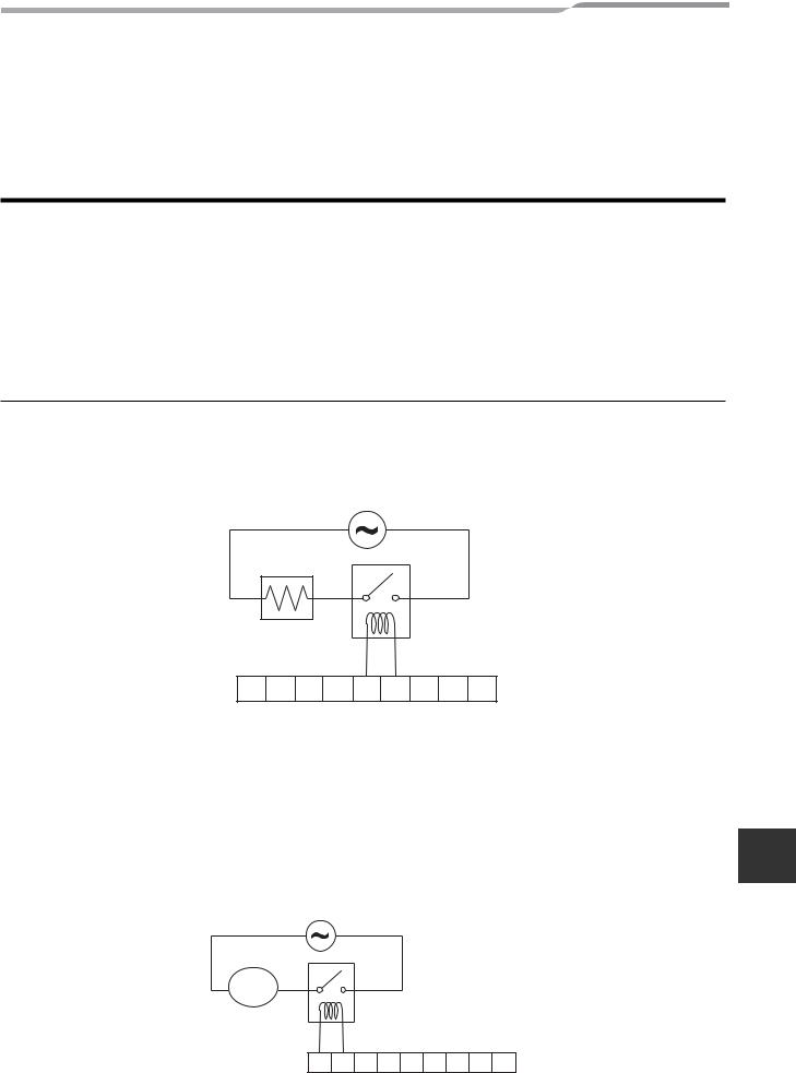
•Connect the external booster heater to the Hydro Unit in accordance with the diagram shown below.
•Connect the coil, of the field supplied contactor, to terminals 5 & 6 on Terminal Block 05. The contactor will energize in the event of low ambient conditions.
•A separate dedicated electrical supply must be used for the external booster heater. This must be connected through the contacts on the field supplied contactor.
▼Fig. 7-23
Booster Heater
1 |
2 |
3 |
4 |
5 |
6 |
7 |
8 |
Terminal Block 05 |
9 |
Electrical connection for external additional pumps
•The Hydro Unit has the facility to connect an additional circulating pump, if required, into the heating or cooling system.
•There is an output available from the Hydro Unit. AC230 V 1 A (maximum) is available from each output. The output for each additional pump is synchronized with the operation of the main circulating pump inside the Hydro Unit.
• Connect the additional pumps as shown in the diagram below. |
EN |
•Connect external pump 1 to terminals 1 & 2 on Terminal Block 05.
•Install external pumps so that their motive power does not affect the internal pump.
▼Fig. 7-24
Pump
01
1 |
2 |
3 |
4 |
5 |
6 |
7 |
8 |
9 |
Terminal Block 05 |
|
– 25 – |
24-EN |
Hydro Unit |
Installation Manual |
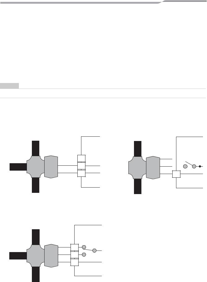
3-way valve (diverter) connection
Required Valve Specification:
Electrical Specification: 230 V; 50 Hz; <100 mA
Valve Diameters: Port A, Port B: Ø 1 1/4"
Return Mechanism: 3 types of 3-way valve (diverter) can be used.
Set the 3-way valve in use with the DIP switch SW13-1 on the Hydro Unit board.
|
|
SW13-1 |
|
|
|
Type 1 |
2-wire spring return |
OFF |
|
|
|
Type 2 |
3-wire SPST |
OFF |
|
|
|
Type 3 |
3-wire SPDT |
ON |
|
|
|
NOTE
Continuous operation of the valve motor at the fully open position is not recommended.
•The 3-way diverter valve is used to select either domestic hot water or space heating.
•Connect the 3-way diverter valve to terminals 7, 8 and 9 on Terminal Block 05.
•Connect the 3-way diverter valve in accordance with the diagram below:-
▼Fig. 7-25
Type 1: SPRING RETURN
port “A” to Hot water cylinder
port “AB” to Hydro unit
Hydro Unit
TB 05
7
8
port “A” open
9
▼Fig. 7-26
Type 2: SPST
|
port “A” to Hot water |
|
|
|
|
|
|
cylinder |
|
Hydro Unit |
|||
|
|
|
||||
|
|
port “A” |
TB 05 |
|||
port “AB” to |
close |
|||||
|
|
|
||||
|
7 |
|
|
|||
Hydro unit |
open |
|
|
|||
|
|
|
|
|
||
|
|
|
8 |
|
|
|
|
|
|
|
|
|
|
9
port “B” to Room heating or cooling
▼Fig. 7-27
Type 3: SPDT
port “A” to Hot water cylinder
port “A” close
port “AB” to
Hydro unit
open
Hydro Unit
TB 05
7
8
9
port “B” to Room heating or cooling
port “B” to Room heating or cooling
25-EN |
– 26 – |
 Loading...