


HVK-6M40A
Toshiba HVK-6M40A, VK-6P32A, HVK-6P40A, VK-8M40A, VK-8P40A Installation Operation & Maintenance
...
lvlav.
31, 2012 9:lSAlVl
TOSHIBA
No
1530
P,
2
Document; GF0776{'I-B
INSTRUGTION$
IilSTALLATION
.
OPEFATION
.
MAINTENANCE
Type
VK
&
HVK
Series
Vacuum
Circuit
Breakers 5-15kV
APPLICABLE TYPE FORMS
(1200A) (20004)
(30004)
VK.6M32A VK.6P32A
I.IVK.6M32A
HVK-6P32A
VK.6M4OA VK.BP4OA
HVK-6M4OA HVK'6P4OA
VK"8M4OA
VK-8P4OA VK-8O40
HVK-8M4OA HVK-8P4OA
,VK.1OM25A2
VK-1OF25A2
HVK-lOM25A2
HVK-I0P26A2
VK-10M40A VK-10P40A VK-10040
HVK-1OM4OA HVK.IOP4OA
vK-6M50
vK-6P50 VK-6050
vK-10M50 VK-10P50 VK-10()50
NOTES:
t) The
designation of
H
before
vK
(i€.
HVKI
dsnot€s that the circuit braaker unit
was assembled
in the USA using domestic
and
foreigri
components.
All
'
relErgnces to modal numbere in thie manual will
be by the numbets following
the VK- and
HVK-.
2l Thi! manuel waB writtan
lor tha Toshiba typ€ form circuit
brsakers listed on
thi$
page
used in coniunction
with Toshiba
cells.
For
circuit
brsek6rs
utilized in
the convereion
of
othsr
equipment, a supplemental
i struction manu8l Should
be obEain6d
from lhe conversion manufacturer.
lssued 2/95.
Supemedee GF077401-A Deted 12194.
N4av.
31 2012
9: l5AlVl
t0, )tu
r,
1
INTRODUCTION
Page i
READ THIS MANUAL carefully
for imponant information about
safety, handling,
installation,
operation,
maintenrnce, and
parts
replacements for
spring-operation-type.
VK
and
HVK
series
vacuum
circuit breake6.
This manual
and all accompanying
drawhg$ should
b6 consid€r€d a
pgrmanent paft
of the equlpmgnt.
They should
be
readily
available
for /eview
and
reference
at all timos.
DIMENSIONS
shown in th€ manual are
metric and/or their 1,.S. equivalgnt.
INOUIRIES
should be addressed to;
Field
$ervice
Department
Toshiba lnternational Corporation
13.l31
West Littls York Road
Houston, Texas 77041
USA
Telephone:
1713't
466"0277
(800)
231-1412
(800)
527-12O4
(Cenada)
Fax:
|'7131
466"8773
ll[ffiFiliilC-l
uaa only Torhtba-authodzad
rBptacamont
padr.
nWiF-MiEl
tiris
equipment
is
de3igned and buitt
in
accordance
with
opptioable
sttetl
etandqrds
in 6l{sct on ttle date of manutactu.c. Unautho.hed
modElcadonr wlll
vold wattalty
and cEn ra:uh ln rwera lnJury, daath and
propsrty
dnmag6, Do not
mak6 nny moditicadons to
thi8
ecpipmefi without
tho
written
tpproval of
Toshiba.
6
TOSHIBA INTEFNATIONAL
CORPORATION,
1 995
t!1ay.31.2012
9:15Att1
No.
1510
P,
4
TABLE OF CONTENTS
Page ii
SAFETY
RECEIVING,STORAGEANDHANDLING
,........,,4
Receiving and Unpacking
.........4
Acc€pl6nca lnspection
,...4
Lifting for Handling and Moving
" "
'
5
Stotage,
..'.". t,
lnspection During Stolage
........-
6
GENERALDESCRIPTION
.,..,...7
gafety
Deviceg
........' I
lnterlock Lever , ,
........9
Sell Coupling Type Secondary
(Csntrol
Circuit)
Disconngcts
, .
'
. . 10
INSTALLATION
.,...,
11
Service Conditions
....
..'...... 11
Bating..
...... 11
Lifting tor lnstellation
',.'
13
Using the
Portable Lifter
...'.'.'. 13
Moving the Circuit Breaker in the Cell
.-.....15
PRE-ENERGIZATION
CHECK
..,, 18
General ,
.. ... .
18
Elactrical Checks .
...... t8
oPERATtoN
..,,"..,
19
Manual Operation.....
.'..'.". 19
Electrical Op€ration
.
'
... 20
Controf Ckcult
Oparation
..,.
'., , '
ZO
Closing Sequence.....
..'.20
Charging Sequence
'.......20
Tripping
(Oponing)
Saquanca
....."' 20
Mechanism Operation
....25
Closing .
,.......
25
Charging
.......' 25
Tripping ,
.......
25
Trip Frae
.""...25
MAINTENANCE
...,,, 26
Maintenance Progtam
.... 26
Maintgnanca R€cord
,
.,"
26
Servioing
Equipment
..... ?7
lnspaction
and Maintenance
Type3..
'..'.'.2e
lnspgction and
Mainlenanc€
lnterv8ls
'.
', ',.
30
Wipe Measutement
...
......
'..
36
Vacuum
Chack
,
..-...'
37
Troubleshoothg Guidelines
.,"".41
Replacement of
Parts .
... 44
Auxiliary Switch,
"'.'....45
Closing Coil
and Trip Coil
,
..
....
' ' '
47
Control Citcuit
Board .
..'..4S
Control Circuit Board Fuse
'."'
. . .. .
51
Feplacement
Pans List
...
53
CoNVERS|ONS
.
^....
54
WARBANTYandLIMITATIONOFLIABILITY
..'..'' 57
tvlav
31
2012 9:
l5Al!1
[1o
1530
P5
SAFETY
Page
1
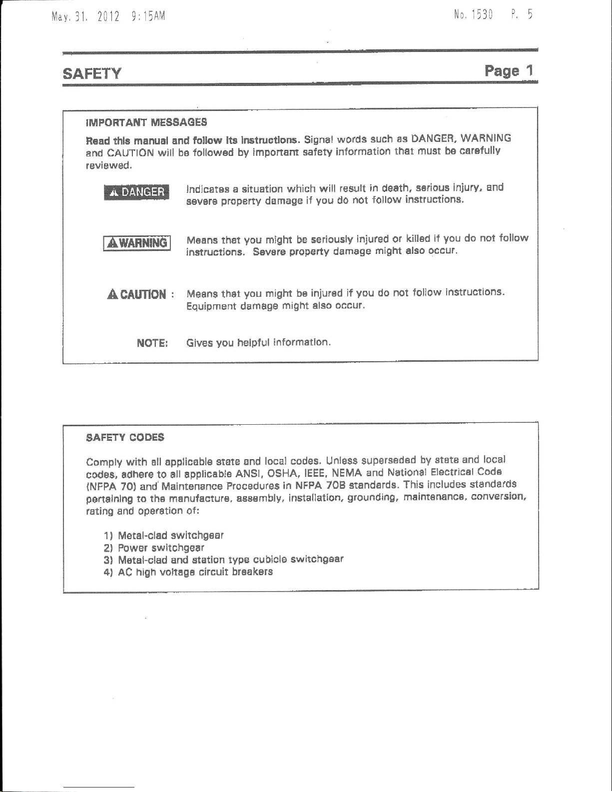
IITJIPO
RTAI{T MESSAG
ES
R€ad
thls manual and follow
lt3 Instruotlons.
Signal
words
such as DANGER'
WAFNING
enrf CAUTION
will bB lollowsd
by imponam
safety information
that
must be catafullv
reviewed.
lndjcates a
situation which
will tesult
in
death,
serious iniury,
and
s€vsrB
propeny
damage
if
you
do
not follow
instructions'
|[mmiilG"l
M66n3 that
you
might be seriouslv
iniured
or
killod
if
you
do
not lollow
r-:'-J
instructions, S€vste
property
demage
tflight
also
occur.
A CAlmOil
: Mean3
that
you
might be
injured if
vou
do
not follow
instructions.
Equipment
damage
might elso occur.
NOTE:
Gives
you
nelpful
informallon'
SAFETY
CODE$
Comply
with all applicable
state and
local codes' Unless $upsrssdad
by etate and
local
codei, adhere
to all appliceble
ANSI, OSHA, IEEE,
NEMA and
National
Eteclrical
Cods
{NFPA
70) and'Maintenance
ProcEdures
in NFPA 708
standarde.
This includes sl6ndards
penalnlng
to
the manufaetu.e,
a88embly, installation,
grounding,
maintananca, conversion,
lating and ope€tion
of:
1
)
Metehclad switchgear
2) Power swltchge8r
3) MetaFclad
snd stEtion
typg cubiclE switchgsar
4) AC hiqh voltagB
circuit braakers
llav.
3I 2012
0,
15AM
No. 1530
P6
Page 2
SAFETY
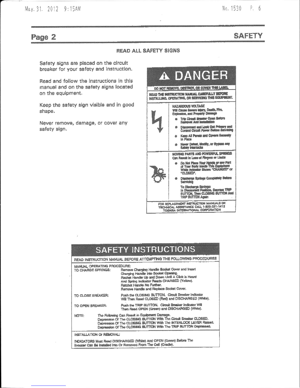
READ ALL SAFETY SIGNS
Safety
slgns are
placed
on ths circuit
breaker
for
your
safety
and imtruction.
BeEd and follow tha
instructions in this
manual
and on tho safety
signs locatod
on rhe equipment.
Keep
the sefsty
sign viaible
and in
good
shape,
Never removg, damag6, or covat
any
safety sign.
ElDltagr|rtnfilrlclElrltr
ictllim.
eemre
orlanrrr
lta
E[Et
H^TNHEH'IE
r ArN.irfit'
m,tla
tFGaHtE
. tt clal tFq-llll
i-HirdE
. DEEdtgqt
trLrd
arqrc(ilt* Hlf,ln*f
a
irll
trdrlecEtd
hrb
. ffi lrrildr,iq
ntt
!.ltffilr
*flm
rrrlt
r[ ffiEF]a
!!
cltlrdhLilriFtLE
. btuhht!5ttrttll
dy-tCrttlUEl*'E
trf
rrE t&r'ClUfiFa
'd.aEr,
.
orF
tFtt cF#tbr
tdfr
FEAD tt€tnrJdflol{
t&lluAl BEFoRE ATTElptlE
THE
FoUOlltttt
pfiQOEltJfiES
uAr{rAl oFEE
s PmcEDt'Ae
To $lA*E
stf,Negl n
.g chlrliE f5t*
toqrl cevst
crd hE
(t1.
ii!
;htd. bro Soqbr
OF..fte.
BtEa
-l}
t& tlF fd
Dcttt
unfl a cH b tLtlll
erd sEtla
rr&or R.le ofiAndD
g.lqr).
Rd€ ldt{e
Fdt r'
ilttHr
l5t rtd
R€tbat 8o.ld
Csnr'
1rO.La!!FSREAIGRT
Fllhdlrat,(!
G eJfllll
Ctqi Es'b.lre
\irf, Tllql
R€rd
ctoeED
(is0
{td OlSCt{AffiED
0rn'}
7o OPB{ BRE
xE t h.lr
A. TflrP
gJftSL
Ch * hdr..li*dor
lr
Thrl h
@sl
(Glifit
rd ol8C+lrhOED
$nr.!
lfiftE
fhe Folci'rn C||t
R€sa
h Ef,+trsr Olttqg.
o.dgidl
*
rlE cLodta
gt
tTct{
lllfi 1'lr€ drEi
Er*. clllg4r'
aj-r!+*n Oa
The
cr.CElcc BUTllll
Yflt llro wTEH.rffi
lE\rEB Br*rr
D.i.doi Cl Tlta
dr6
E
gufltil
!\{l
lltelilP Jtlofi
D'F t'c5'
NsnLLAfn chElaol/^l.j
ITFEATOB t{$i FFd
OtSfi
RaED
(!lt{t}
Atld OpBl
GlE€o)
8.aort
lttc
gr*.
Cfi tf mH
lllo cjr Fentle<t
lErnn Tll. Ocl
(ffi).

N4av.
3I 2012
9: l5AlV
No
1530
P,
1
gAFETY
Page
3
OUALIFIED
OPERATORS
OilLY
only
quslified
persons
are to
lnstall, op€rate
or service
this €qulpmefi
accordjng
to all
applicabls
codes and established
safgty
practic6s.
A
quallfle
d
person
must:
1
)
Getelully
tead th6 entlte
iGtruction
tnanual.
2) Be $killed
in the
installation, construction
or opgration
of the Equipment
and awa/e Ol
the hazards involved.
3l
Be lrainad
and suthorized to $sf€ly
energizB,
de-enetgize,
clear,
ground,
lockout
8nd
tag circuits
ln accordEnce
wilh estSbli$hed
sefsty
practice.
4) Be trained ahd
Suthorized
to
parform
the service,
maiftenancs or
rspair of this
aquipment.
5)
Be
trained
in the
proper
care
and use of
protectiva
equipment
such as
rubber
glove$,
hsrd hat, safety
glassos,
face shield'
flash clothing, etc.
in
accordance
with
astabllshBd
practlces.
6)
Bp
tr9ln6d
in rendering
first aid.
Nlav
31. 2012 9:15AN4
No.
1530
P.
I
Page 4
RECEIVING, HANDLING
AND $TORAGE
RECEIVIIIo AND UIUPACKING
The
clrcuh breqker
unite
are aubjected to
fEctory
production
testlng
prlor
to
being
packed
and shipped.
ACCSPTAilCE IiI$PECNON
Confirm that
the
circuil breake, unit
is
oompleta,
conect as :pecified and undamaged
trom shipment 6nd
handling.
Upon
recelpt
of the
equipmBnt, do the
following:
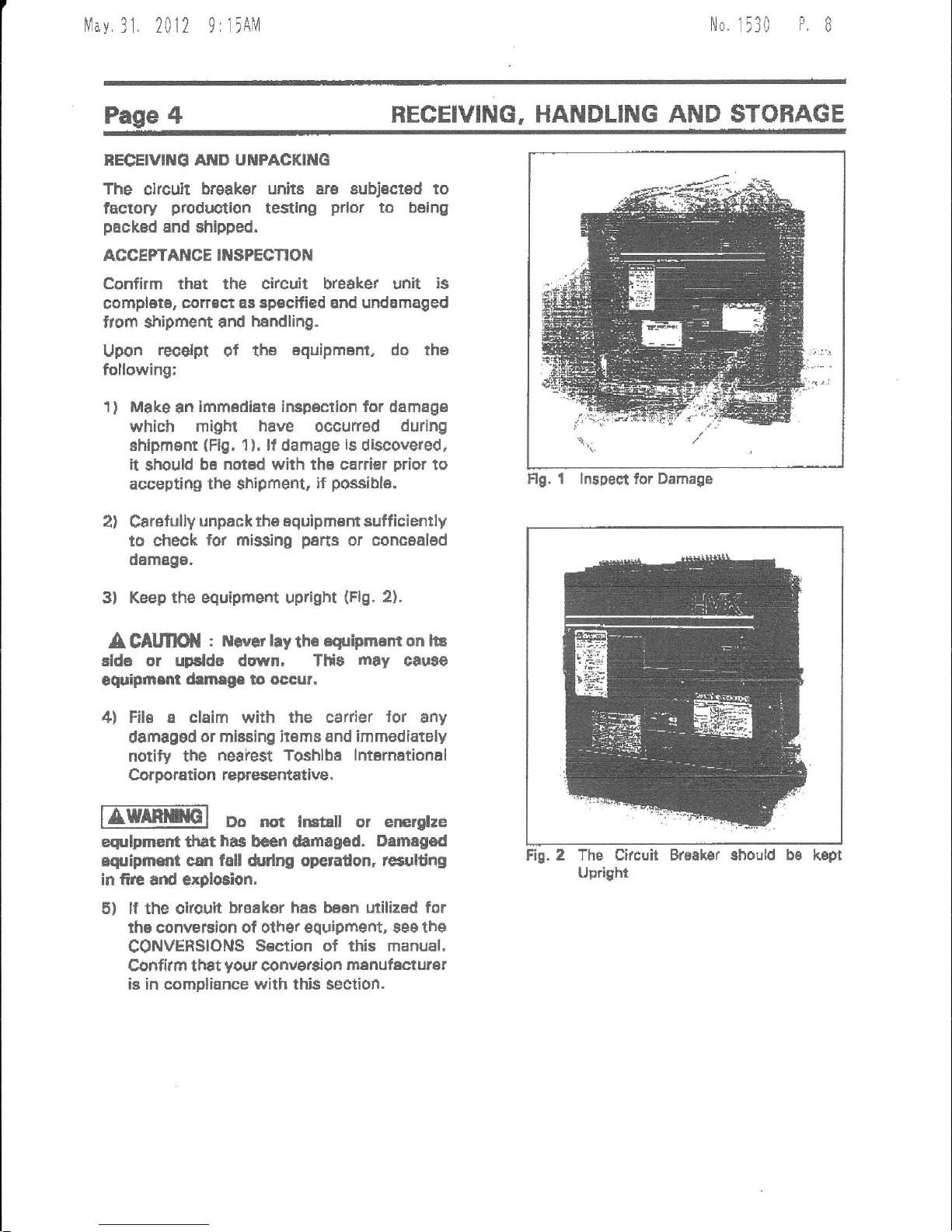
1) Make
an
lmm€diat€ ircpeclion
for damag€
which miotx
have
occurred
durlng
Ehipment
(Fig.
1
).
lf
damage
is
discove.ed,
it
should
be notad with th€ carrier
prior
to
accepting
the
shipment
if
p+asibla.
2)
Carelully
unpack tha aquipmant sufficiently
to cheok
for missing
pens
or concealed
damage-
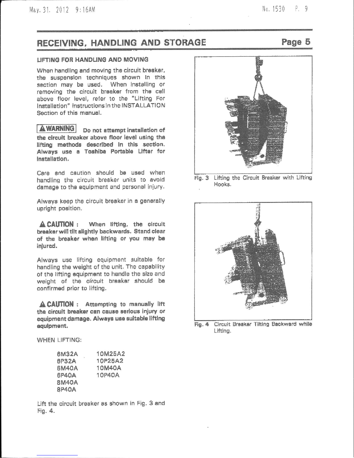
3l Keep the equipmefi
upright
(Flg.
2).
A
CAltflOil
r ltl.vat
hy th6
esripmam on lia
elde or upslde dwn. Tlf$
may
cause
equhmrm
drmrge to occur.
4) File
a
claim with the
csrrier
for
$ny
damaggd
or missing itsms €nd immediately
notily the
neaiest Toshlbe lnternational
Corporation representative.
IZffil
oo nor i6ral or en€rllze
eqrlpmEnt trat
has
bcan *rflagsd.
Drmegod
iquipmilt can fdl drdng operadon, tctultidg
in fire snd
exploEion.
5) lf the cucuit
braikor
haa
baen
utilized
for
rhe conveFion of olher equipmert, see the
CONVERSIONS
S6etion ot this manual.
Cofifirm th€t
yo{lr
conver8ion
msnufecturer
is in compliance with
thi$ section.
Flg. t lnspedl for Damaga
Fi!. Z Thb Circuit Brdsk8r Bhould
Uprighr
kept
llav.31
2012
9:16AM
No
1530
P9
RECEIVING,
HANDLING
AND STORAGE
Page 5
LIFTINd
FOR HANDLING
AND MOVING
When
handllng
and
movlng
the
circuit braskdr,
rhe suspension
technlques shown
ln this
saction
may b6 used. When installing
or
removing
th6 circuit braaker
from the csll
above
floor
level, refer
to the
"Lifting For
I nstaltation"
instructions
id the
I N$TALLATIO
N
Sgction
of thie mpnual,
ffmnlGl Do nor atbmpr instattation
of
the clrouit bteaker
above
floot leyel u3ing the
lifting
m€thod8 d€scdbed
ln thls section.
Alway$ u$e
e Tolhibe
Portsbla Llfter
for
lnstalladon,
Care and
csution
should ba
usad when
handling
the circuit
breaker units
to avoid
damage to tha aquipment
and
personal
injury.
Always
keep the circuit bf€aker
in e
genBrally
upright
position.
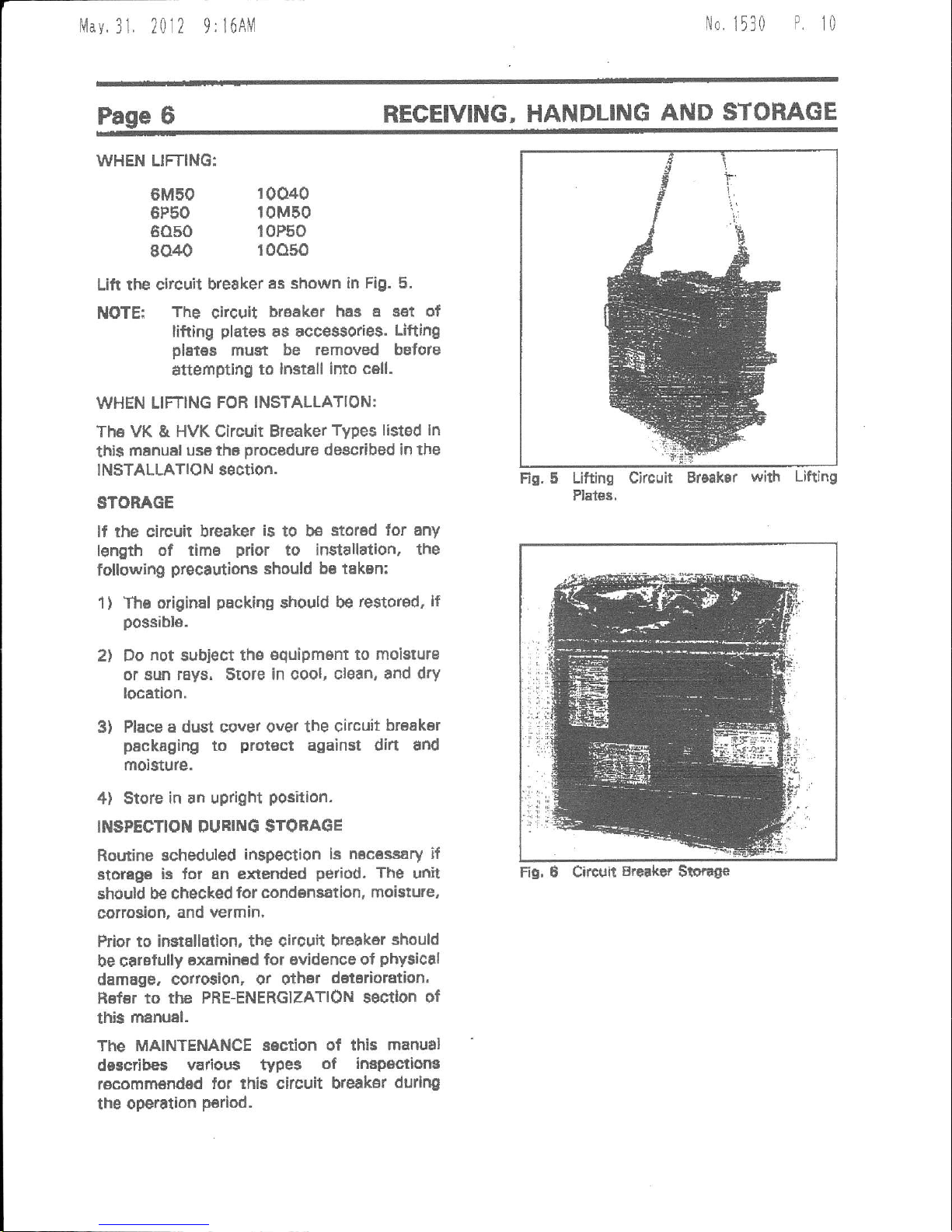
ACAUflON
!
when
littlng,
the oircuit
breekar
vvlll tllt rllghtly backwards.
Stand clear
of
the bteake.
whon
lifting or
you
may be
inlured,
Always use
lifting
equipmant
suilable for
handling ths weight of the
unit.
The
capability
of the
llfting equipment to
handle the size and
weight
of the ciicuit
br6aker should
be
confirmed
prior
to lifting,
A
CAlmON
I
Attempting
to
menually lift
the
circull bruakar
csn caure ledous injury
or
equiprro
t damtge.
Alwey: u:a
eultoHe llftlng
equJpmerTt,
FlE.
3
Lifting
the Cirouit
Hooks.
Breaker
with Lifting
Fig. 4 Circuit
Br6ehsr Tihing Beckward
whils
Lifting.
WHEN
LIFTING:
6M32A
6P32A
6M4OA
6P4OA
8M4OA
8P4OA
10M25A2
10P25A2
10M40A
10P40A
Lift ihe
circuit breaker as
shown
ih Fig. 3 end
Fig. 4.
li1av
31 2012 9:
l6AlVl
Itlo,
1 13 0
P
t0
WHEN LIFTING:
6M50
6P50
6050
8040
Lift the circuil
breaker
as shown in
Fig. 5.
The
circuit
braak€r
ha,B a eet of
lifting
plates
as accessories.
Ufting
pletes
must be
removed before
atterfiptlng
to lnstall into c6ll.
WHEN LIFTING FOR
INSTALLATION:
The VK & HVK Gircuit Breaker
Types listed ln
thi$
manual
us€ the
procedure
described
in the
INSTALLATION
section-
STORAGE
lf the
circuit breaker
is
to be
stored
lor any
length of
timB
prior
to installation,
the
following
precautiotar
should
be taken:
The original
packing
should be
restor€d, lf
possibl6.
Do
not
subject
th€
€quipmBnt
to moisturB
or aun
rays. srote in oool,
cl6an, and dry
locetlon.
Place a dust cover over
the circuit
br€ak6r
packaging
to
prot€ct
against dift
and
moisture.
$tote
in an upright
Position.
INSPECTION
OURING STORAGE
Rouine
scheduled
inspection ls nec6s34ry
if
storage
iE lor En extended
period.
The
dlit
should b€ checked
for condensation,
moi$ure,
cottogion,
and vermin,
ftior to instEllation,
the circuit breaker
should
be crrefully
6xamined
lor ovidence of
phy$ical
damage. cotto$ion,
or othsr
doteaioration.
Hof6r
to thc PRE-ENERGIZATION
ssctlon of
this
menual.
The MAINTENANCE
sEction of this
manual
describes
vatious typ$
of
impsc.tiong
recommsndsd
for this
circuit breaksr
durlng
the
operstlon
P€riod.
REGEIVING,
HANDLING
AND
STOHAGE
t
1
10040
10M50
10P50
roo50
NOTE:
Fig. 5
Lifting Circuit
Plat68,
with Lifting
1)
2t
3)
4)
Fig, e
Circuir
Breekef
S$.ag€
lvlav.
31 2012
9: 16AM
No
1530
P.
tl
GENERAL
DESCRIPTION
Page 7
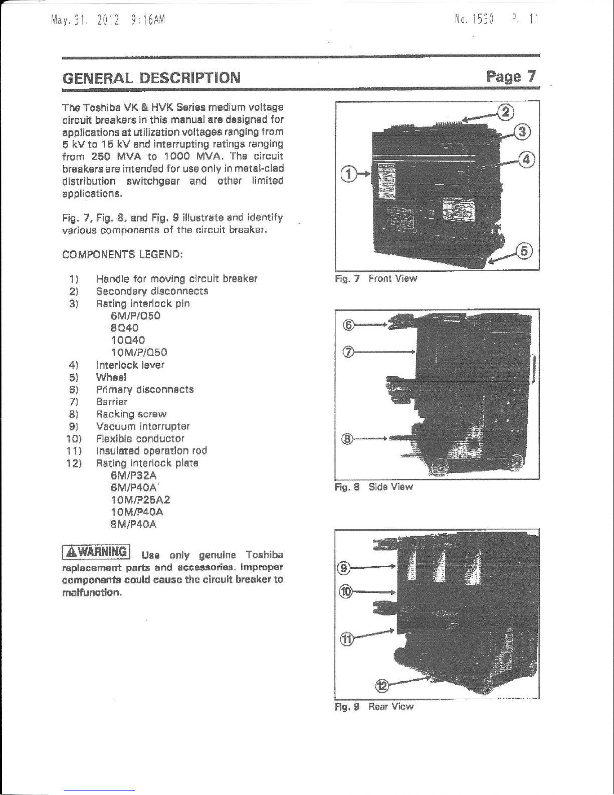
The Toshiba
VK
&
HVK Serias medium voltage
circuit breakers
in
thi6
manuel are dasigned
for
applica offi at utilization
voltages
ranglno from
5
kv to 15 kV and intorrupting ratings
ranging
from
250 MvA
to
1000 MVA. The circuit
breakarg are inlended
for
use only
in metal-clad
dlstriburion
switchgear and other
lifitited
applicttions.
Fig. 7, Fig. 8, and Fig,
g
illust.ate and
identify
various component8
of the circuit b'eaker,
COMPONENTS
LEGEND:
1
)
Handle
lor moving circuit breakar
2l Secondary disconnects
3) Rsting
intBrlock
pin
0M/P/oF0
8040
10040
10M/P/o50
4l lnterlock lever
5)
Whssl
6) Primary disconnscts
7l
Barrier
Bl
Rscking scrsw
9)
Vacuum interrupter
1O)
Flexible conductor
11) lnsulatsd
opsration rod
1Zl
Bating interlock
plat€
6M/P32A
6M/P4OA'
10M|P25A2
10M/P40A
8M/P4OA
UBE only
g€nulne
Toshiba
replacBm€nt
parE
and accatsod68.
lmproP€r
componEl'tr
could cauee the citcuit breaker
to
malfunction.
Fis. 8 Sids
View
Fio.
7 Front Viaw
Fls, I
Rear View
Mav.31
2012 9rl6AM
No,
1530
P.
12
SAFETY
DEI/ICES
Sat61y
inr€rlockg and
guards
sre
provid€d
as
an
iftegr8l
pen
ol th€ €quipment deslgn.
These devices are
provided
for
your
BafBty.
Never Defeat, Modfy or
Bypa*
any Satety
El6vlc53,
lmerloeks. or
operadng mechanfim.
Ttrt world
make
the
enripment
unsati. Flre. erploCon,
gevere
Ir{ury,
death, and
propafi
damage could
occul,
nml
Do not o'€rate th* equipm€nt
unle$s all soverE
and
panelr
sr€ ln
place-
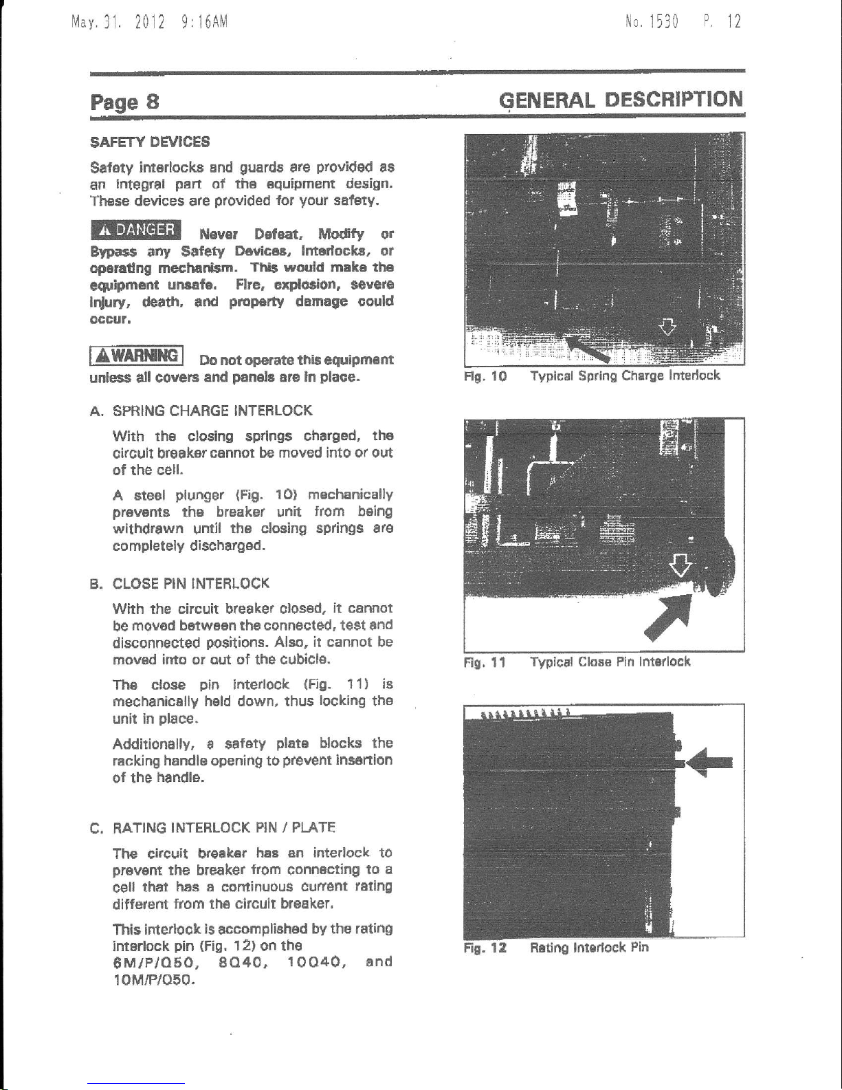
A. SPRING CHARGE INTEFLOCK
With the clesing springs
charged,
tha
circuft break€r
cannot be moved into or out
of the cell.
A steel
plunger
{Fig.
10} mechanically
prawms
th€
breakel unit
from being
withdrawn
until
thB
closing
sp ngs 8re
completely dischargod.
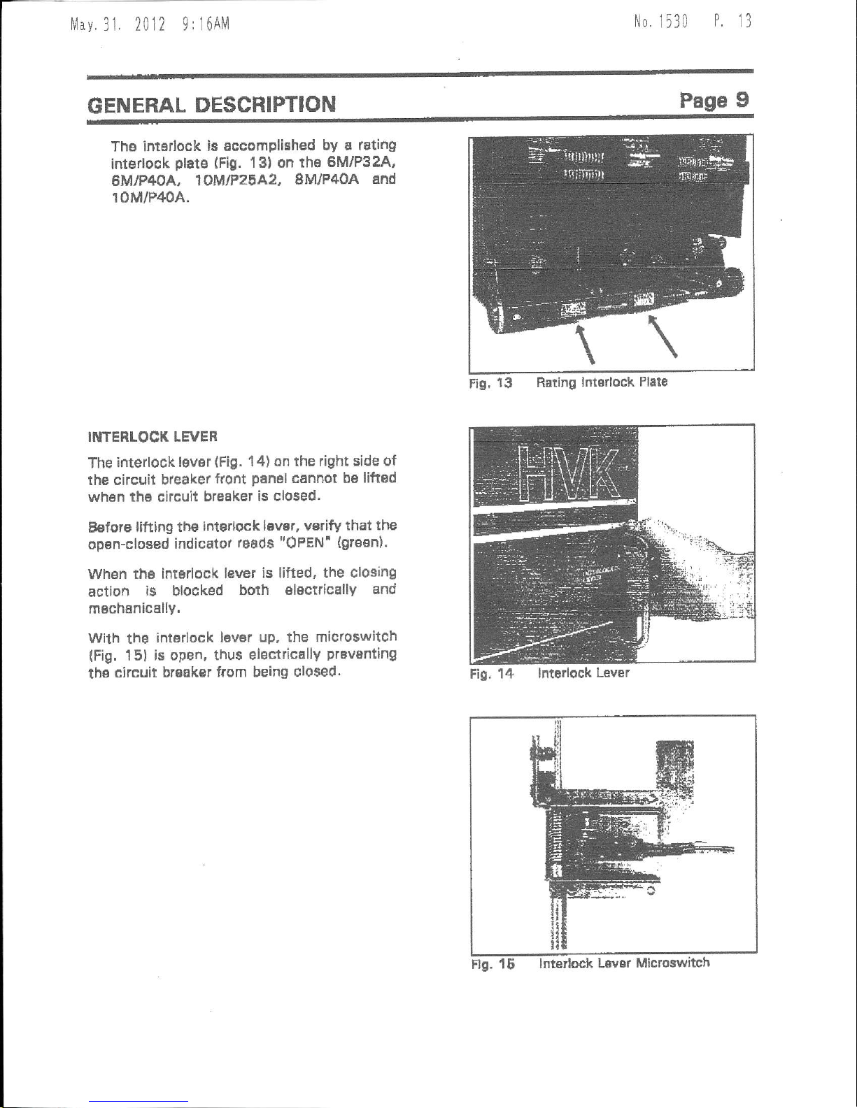
B. CLOSE
PIN INTERLOCK
With the circuit bteaker olosed,
it cannot
be
mov6d betwaen the connected, test and
disconnected
positiorc.
Alao, it cannot be
mov6d
into
or aut of the
cubicl6.
Th6 close
pin
ifiterlock
(Fig.
1 1
)
is
mechanically held down, thus
locking
the
unit in
place.
Addition€lly, a salety
plats
blocks the
racking handle opening to
prevent
insartion
0f
the
handle.
C. RATING
INTERLOCK PIN / PI-ATE
The citcuit H€ak€r
hsB sn interlock to
prevsnt
the breaker
fiom
conn6cting
to a
c€ll
that hae a cominuous
cufierrt
reling
difterent
from
the
circuit br6aker,
This intertock
is
accomplished
by the rating
intarlock
pin
(Fig,
l2) on the
8M/P/O50,
8O40.
1OO40, and
10M/P/O50.
ENERAL
DESCFIPTION
Rs, 11
Typical Close Pin lntorlock
Flg. 10 TypicNl Spring
Charge
lntedock
Mav.31,
2012
9:i6AM
No,
1530
P
t3
GENERAL
DESCRIPTION
Page
9
Ths intddock
ie accomplished
by a rating
interlook
plats
(Fig.
1 3) on the
6MlP32A,
eMlP4OA,
19MtP2gA2,
8M/P40A
and
10M/P40A.
INTENLOCK LEVER
The
interlock
lever
(Fig.
'14)
on the right side
of
the circuit
bleaker
front
panal
cannot be liftad
wh6n
thB circuit breaket
is clo$ed.
Belore
lifting th€
interlock lBvsr, vsrify
that the
opan-closed
indicator
reads
"OPEN'
(grosn).
when
tho interlock lever
is lifted, the
closing
action
is
blocked
boih
electrically
and
rnsch6nically.
wilh
the
interlock
lever up. the micloswitch
(Fig,
151 is
open, thus electricallY
prevsnting
the
circuit brsak€r from
being closed.
Fig,
13 Rating
lntorlock Plate
Fig,
14 lnterlock
Lever
f/av
31. 2012 9:17Ah1
No,
1530
P.
14
Page
1O
GENERAL
DESCRIPTION
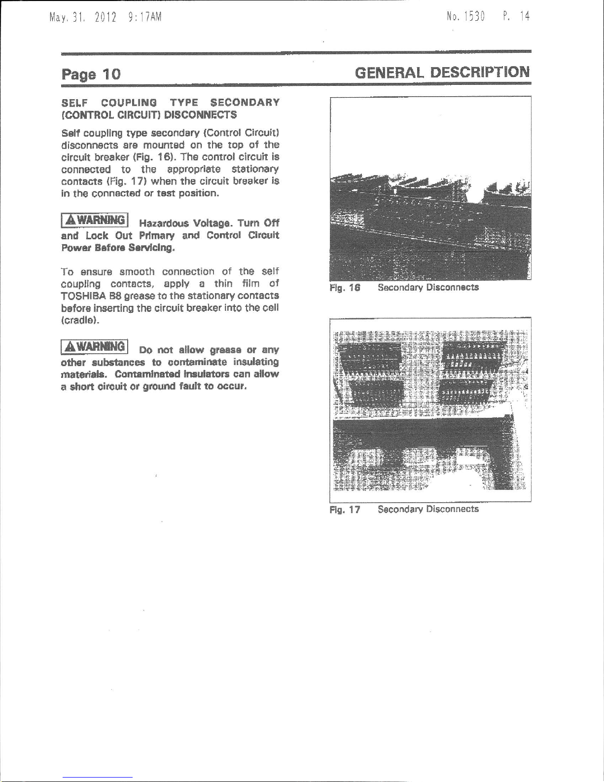
SELF COUPLINE
TYPE
$ECONDAEY
(col{TRor
crRcurr) DrscoililEcT$
Sslt coupllng
rype
secondary
(Control
Cl.cult)
disconnects
Er6 mountsd on the top of the
circuit breaker
(Fig.
16).
The comrol circuh ia
connected to the approp/idte $t8tionary
contacts
{Fig.
17} when the citcuit breake.
is
ln
tbe
connestsd
or t6st
position.
fA-l
Hazardorr6 votraga,
Turn otf
and Lock Out Pdmary and Control Circuit
Power B6for€ Sarvlclqg.
To snsur€ smooth connection
of the self
coupllng
contact8, apply a thin film ol
TOSHIBA
B8
grease
to
th€ stationary
cornacts
before insening the
circuit breaker
irto
the cell
(cradle).
nWAf,rcl
Do mt alow
greese
or any
od|3r aubstanccs to cortamid
te
insulating
mNtcriab. Colrtrmlnat
d ln ulatots can allow
a shon
circuit or
ground
fadt to occur.
Fr0.
17
Secondary
Disconnecis
Flg. 16 Secondary
Di8conn€ct8
lvlay.
31, 2012
9:lTAlVl
No
1530
P.
1t
INSTALLATION
Page
11
SERVICE
CONDITTOilS
EWAEtlilG-l
Do nqt ini1pll
rhis
aquipm.m
in areas
where unurual
serviae condition$
erist.
Using thiE €quipm€nt
ln othsr than uaual
aervlce
condffod$ can
relult in squipm€nt
fallura,
Toshibs
VK
&
HVK
$eri€s
Circuit Brsak€rt ara
intended
for
use
in u6ual servioe
conditions as
dellndd
by ANSI. The
temperatule of the air
(arfibient
air temp6raturs)
surrounding
the
Ewitchgear
should be
between the
limits of
-3OoC
l.22oF)
snd +4OoC
(104oF),
The
altitude of the equipffient
instsllation should
nor exceed
3300 ft
{100o
m},
IUOTE;
Temperature,
ehitutle ot othar
conditions outside
of the usual
limitt
may raquire derating
or other special
equiPment.
Contact ToEhiba
lntsrnational CorPoration
for
additional lntormstion.
RATIIVG
Prior
to
ln$tallation:
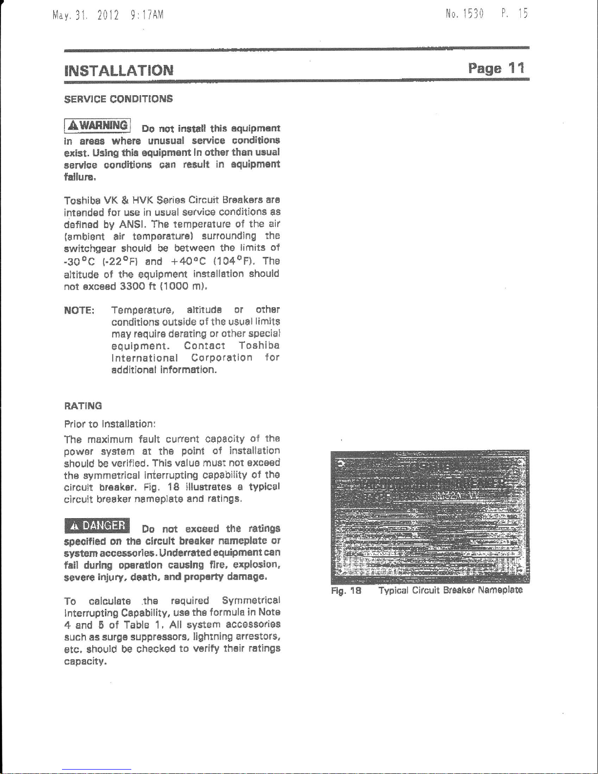
The
maximum fault curredt
capaoily
ol tho
powsr
sy3t6m
at thB
point
of
installstion
should be
verified. This
valug must not exceed
ths symmetrical
interruptino eapability
ot the
circult
bteaker.
Fig. 18 illuetrEtes
a typical
circuit breaket
nameplatg
and
ratings.
Do not exceed
the
tati
ga
$pecified
on
fi6 circult
braak€r nameplate
ot
aystem acces5orie5.
undefrated
equipment
can
fail
durlng oparallon caudng
flre, erploaion,
sgvgrg
inju
. d6rth,
ind
proP.dy
damagc,
To calculat€ .th€
required Symmetrical
lnterrupti
g
Capability.
usatheformula
in Note
4 and 5
of Table 1, All system
accss9origs
Buch as surge supprasaors,
lightning arlestols,
etc, should
be checked
to
varify thsir ratingi
capacity.
Flg. 18 Typical
Ciacuit Br3aker
Nsmsplac
1,,1av.31.
2012 9:17AM
N0.
1530
P
16
Idofiificdidr
RddVdlr
::;..itH6l
it:iji6flil;&l
i"i;6,1.{iri:
|-., i..i i:lc
.3frNt
ltl.i irE8li.i
"t:i
'.
Er!
r!t5! r
+.r'ri ,
r}'
H
f,..!H
V*{t
0t
!.Yl
tldt
3tln
{xv t
r4ahg
tffi)
r#*
r,iri{
Dty, V
!E
6a.d
Htr-
E
{rYl
t2f
Y*rt
nrrF
t
cat'
ht
\'hrg
tsr
lhr
rl
€oll
{At
ESA
Atrr
*sln
ht}rg
la
lls.
rvt
lrat
t4)'
F4ruy
VB
lvl
AIE2A
6Fil2A
4.16
!t.16
2SO
150
1,76
4.78
't.24
1,21
l9
to
60
m
1200
zxxt
29
za
I
3 2
E.a6
s,gt
3lt
3A
a0 6E
5A
al,tloA {rf
6goa
of
4.lE
!t.t6
s60
950
\7d
d76
t-d
I
O
te
IE
60
@
l roo
zu)
,t1
3
2
2
4.78
1.',1c
4t
4l
41
+1
SB
6E
Etfio
6F60
6(rc
4,16
4.16
ILI
E
Ito
360
361)
47',
+76
4.ta
l-lr
t.t3
t0
19
19
60
60
c0
t tod
20@
3000
tll
4t
4t
I
I
s
,
z
2
lto
a.o
40
43
att
49
49
a0
4S
7t
7t
7e
Ar,lbA
I'IIOA
80,to
tlf
7,4
7.2
300
6('0
500
d.:5
a.r3
a,z5
l.r5
LB
t.lE
36
3t
IE
95
tt
SE
I400
20s
gooo
33
t3
3
a
s
2
2
2
4.6
6,6
6,8
41
4i
a1
41
d6
66
6A
I6MfiA'
tot:lt l 13.4
500
5m
t6
l5
t
-30
tJo
36
t!
gE
s
I uao
zn
16
IE
3
s 7
I t.5
l t,3
,3
23
tt
t3
a7
t7
toM{an
't{tFttoa
roq40
tll'
1C.E
I
s.a
l3.a
750
7A
7
IE
ll
IE
t.ao
1.30
t
-so
a8
36
3t
6
t5
t6
1200
:000
3000
2A
28
2E
3
3
2 11.5
36
t6
86
3g
36
36
5S
EA
6E
roP4oA fil
lmto fl r
l!-6
13.8
1066
100(l
t3
IE
t.0
t-0
3C
36
t5
s
2o0o
3000
B7
37
a 2
1E
15
37
g7
l7
6A
F9
lotFo
totto
iooEo
19.t
13,t
t3,8
t 000
looo
1000
16
t5
l5
!
-lo
l,$
1.30
36
3!
36
s
E6
1206
2l'qt
30m
s7
g7
3
I
3
2
2
i t,5
I 1,5
116
49
.t6
4E
4{
*0
46
't7
77
17
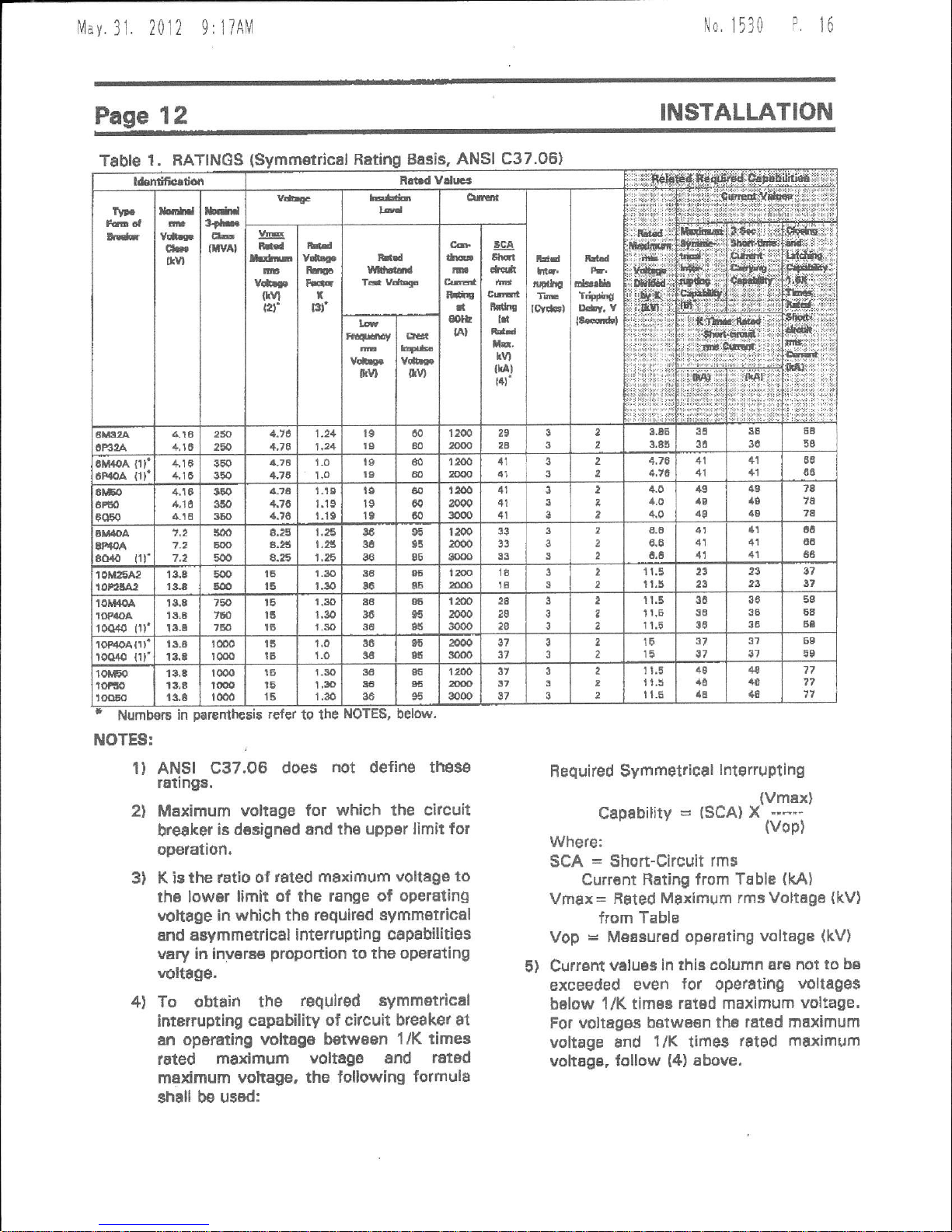
Table
1 . RATINGS
Numbol6
ITIOTES:
Basis,
ANSI C37.06)
r€fer
to the
r)
2l
3)
ANSI C37.OB
does
not
define
thes€
r6tings.
MEximum voltage
for which lhe circuit
breaker
i6 d€signed and th6
upper limit for
operation.
K ic
the
latio
of
rSted maximum
vollage to
th6 lowar limit
of the range ot
opetating
vohage
in which tha roguir€d
symm€trical
and asymmefiical
interrupting cap8bilitiss
vary in inv€rs€
proportion
to the oper€ting
voltSge.
To obtain the
requked symmetrical
interrupting capability
of citcuit breaker
at
an
operEting voltsga betwsBn
1/K times
Irted
m€ximum
voltage
snd
ratad
maximum vohage,
the tollowing formulS
shall be
usBd:
Required Symmetrical
lfierruptlng
(vmex)
Capability=(SCA)X*-*
(vop)
where:
SCA = Short-Circuit
rms
Currant
Rating from
Table
(kAl
Vmax=
Faled
Maximum rms Voltega
{kV}
from Table
Vop
=
Measured
operating
voltage
(kV)
5) Crlrrsnt
veluas in thb column
are not to
be
excEeded even
{or
operatihg
voltages
below
1/K tim6s
rated maximum voltage'
For voltages bstwBsn
the ratad maximum
voltage
8nd
l/K
times
rated maximum
voltage, lollow
{4)
above,
4)
Nlav
31. 2012 9:liAM
No.
1530
P
17
INSTALLATION
Page 13
LIFTING FOF INSTALLATIOil
lJnlika the
lifting
procedures
recommended
in
the
FECEIVING,
STORAGE AND HANDLING
section,
Lifting
for lnstallation
pulposas
raquires a different technique,
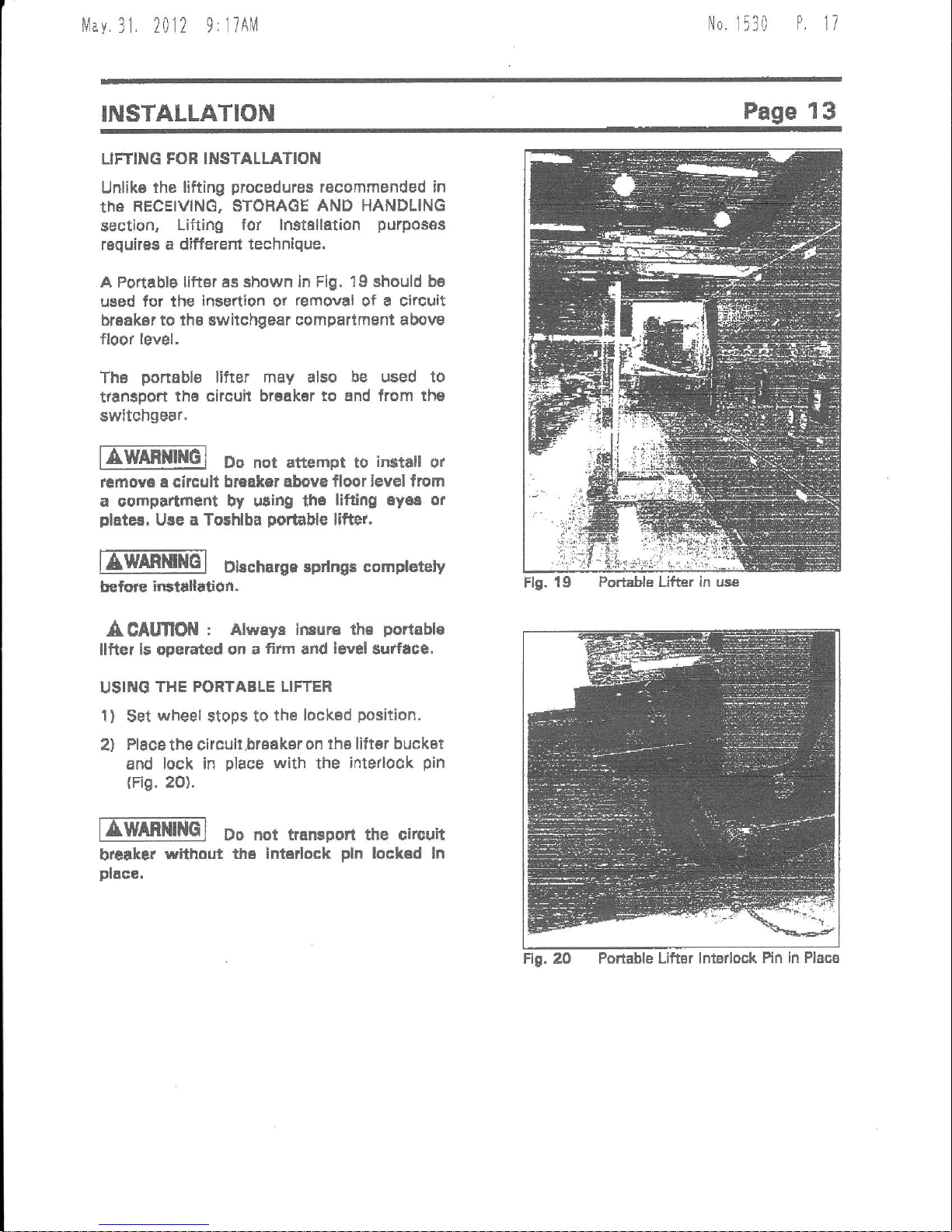
A Portablg
liftdr ss shown ln Fig. 19 should ba
used
for lhe insettion ot
removal
of a clrcuit
br€ak6r to th6 switchgear
compartment above
floor level,
Ths
ponable
lifter may also
be used to
trtnsport
ths circuit brsakar to 6nd
from th€
switchgear.
EWffiMt{6]
Do not
attempt to
irstar
ot
remova
a circult
breaker abova floor level
from
a
compartmefit by uting th6
lifting 6y68 or
plater,
Ure a To5hlba
portable
lifter,
lIffiEl
Dbcharge sprtngs
compt€rcly
ffilre
irHtallution.
A CAtmOil
: Alwaya lnsurs the
portibl€
llfter ls operated
on a
fififi
and
l€vel
Surface.
USIilO
THE PORTABLE LIFTER
1)
$et
wheel
stops to
the
lock€d
position.
2) Place the circult,brsaksr
on lhs liltBr buckat
and
lock in
place
with
the
inte,look
pin
(Fig.
2o).
EEm[im]
Do nor traffipon
the circuit
breraker
without
th€ intsrlock
pln
lockad
ln
place,
Flg. 19
Po*able Lifter in use
ng.2O
Portable Lifter lntsrlock Pin
in Placg
klay
31. 2012
9:18AM
No.
1530
P
18
Page 14
INSTALLATION
lIffil
Do nar rrrEport the vac.um
Clrcuh
Ercaker in dle dc{iNted
pocition
whila
udru
por$lc
llfter,
3l Unlock
the
wheel
stops and
move the lifter
into
position
in front of
the
oell.
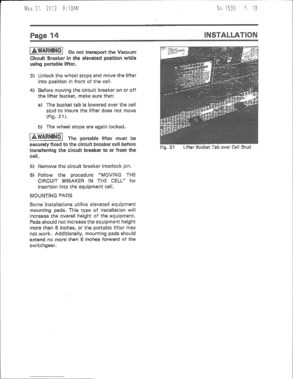
4l Before moving the citouit hreaket on or off
th6 liftor bucket, make sure that:
al The buckst tab is lowered over the sell
stud to
lnsure
the
lifter does not movs
(Fig,
21).
b)
Ths wheel stops Ere again locked.
nmmG]
The
porrdue
riftGr must b6
s€cu]€ly flx6d to ths clrcult breaket cell befu|e
traGfcrdng the cirllir't
k..ler lo or from lha
cell.
5) Ramove
the circuit bteaker
ifiterlock
pin.
6) Follow the
procedure
"MOVING
THE
CIRCUIT
EREAKER
lN
THE
GELL" for
insertion
into
the equlpment
cell.
MOUNTING
PADS
Some installations
utilize
elevated equipment
mounting
pads.
This ryp€ of irEtallation
will
increa$e
ths
ovorell heigtrt of thB Bquipment,
Pads should not increa$e the equlpmsnt
height
more
than 6 inches, or tho
ponable
lifter ftay
not work.
Addltlonally,
mounting
pads
should
ext€dd
no moru than 6
inches lorward of the
switchgBar.
Lifar Buckat Tab
over
Cell Stud
Eq,
2l
|!lav
3l.
20l2 9
r
lBAM
No,
1530
P
19
INSTALLATION
Page
15
MOVING
THE CIRCUIT
BREAKER
IN THE
CELL
lilE@
Ftre and exptoiion
harard.
Trip
clrcuit
ba€ekar
opan and dlecharoa
sptlng$
b€lore
attempting
lemoyil
or
instellation.
ITMRNINGI
unh
conratns
powerrut
sprlngr.
Discturge ep,ingc
completely befora
rswlclng,
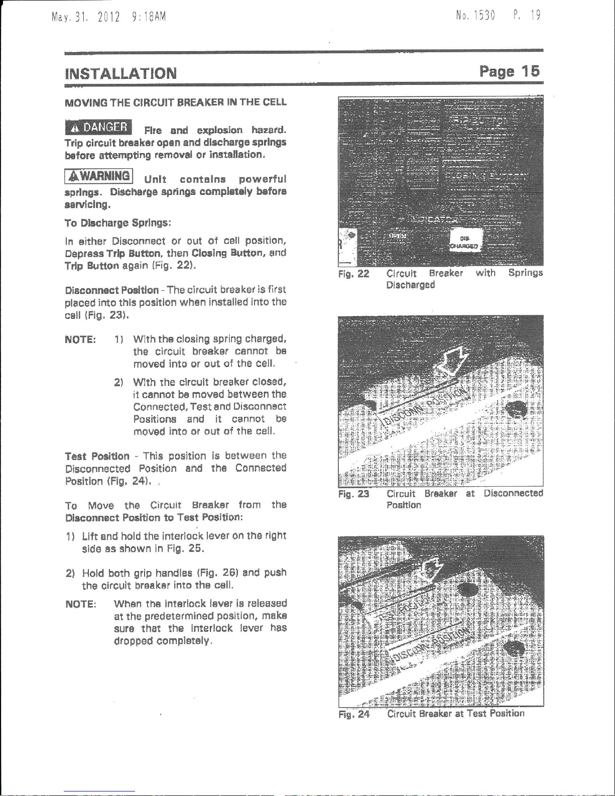
To Dkcharse
$prlngs;
ln either
Disconnect ot out
of
cell
position,
Dep.ess
Trlp Bjtton, then Clo3ing
Button,
and
Trlp
Eutton
again
(Fig.
22).
Disconnact
posltlon
-
The circuit
breaker
is first
placed
into
thlr
posilion
whsn installed
into the
cBll
(Fig.
231.
Fic. 22
Clrcult
Breaket
with
Dlscharged
Springs
NOTE:
2t
1)
T6Bt Poiiffon
Disconnected
Position
(Fig,
Wlth th€ closing spring charged,
the circuit
brgdker
cannot
bB
moved into or out
of the cell'
With rhe circuit
breaker closed.
it cannot
be moved between
the
Connected,
Test
snd
Disconnact
Positions and
it cannot
be
moved into ol oui
of the cell,
-
This
position
is between
the
Position and th6 Connected
24t,
,
Dbconnected
1)
To
Move the
circuir
Br€akEr trom
the
Dbconnact
Fosltlon to
Te3t
Position:
Lift and
hold the inlerlook lever
on ths
rlght
sid€
as shown in
Fig. 25.
Hold
both
grip
handles
Fig,
26]
and
push
the circuil
breaker
into the cell.
2l
Whsn
th6 interlock laver
is released
at the
predetermined
position,
mak€
sUrS that the
interlock lever
has
dropped
compl€t€ly.
 Loading...