


 Loading...
TOSHIBA
Digital Solutions Division
Digital Business Telephone Systems
CTX28, CTX100-S, CTX100 and CTX670
Installation and Maintenance
Manual
June 2004

Strata CTX28, CTX100 and CTX670
General End User Information
The Strata CTX28, CTX100 or CTX670 Digital Business Telephone System is registered in accordance with the provisions of Part 68 of the Federal Communications Commission’s Rules and Regulations.
FCC Requirements
Means of Connection: The Federal Communications Commission (FCC) has established rules which permit the Strata CTX28, CTX100 or CTX670 system to be connected directly to the telephone network. Connection points are provided by the telephone company—connections for this type of customer-provided equipment will not be provided on coin lines. Connections to party lines are subject to state tariffs.
Incidence of Harm: If the system is malfunctioning, it may also be disrupting the telephone network. The system should be disconnected until the problem can be determined and repaired. If this is not done, the telephone company may temporarily disconnect service. If possible, they will notify you in advance, but, if advance notice is not practical, you will be notified as soon as possible. You will be informed of your right to file a complaint with the FCC.
Service or Repair: For service or repair, contact your local Toshiba telecommunications distributor. To obtain the nearest Toshiba telecommunications distributor in your area, log onto www.toshiba.com/taistsd/locator.htm or call (800) 222-5805 and ask for a Toshiba Telecom Dealer.
Telephone Network Compatibility: The telephone company may make changes in its facilities, equipment, operations, and procedures. If such changes affect the compatibility or use of the Strata CTX28, CTX100 or CTX670 system, the telephone company will notify you in advance to give you an opportunity to maintain uninterrupted service.
Notification of Telephone Company: Before connecting a Strata CTX28, CTX100 or CTX670 system to the telephone network, the telephone company may request the following:
1.Your telephone number.
2.FCC registration number:
•Strata CTX28, CTX100 or CTX670 may be configured as a Key, Hybrid or PBX telephone system. The appropriate configuration for your system is dependent upon your operation of the system.
•If the operation of your system is only manual selection of outgoing lines, it may be registered as a Key telephone system.
•If your operation requires automatic selection of outgoing lines, such as dial access, Least Cost Routing, Pooled Line Buttons, etc., the system must be registered as a Hybrid telephone system. In addition to the above, certain features (tie Lines, Off-premises Stations, etc.) may also require Hybrid telephone system registration in some areas.
•If you are unsure of your type of operation and/or the appropriate FCC registration number, contact your local Toshiba telecommunications distributor for assistance.
•CTX28 FCC/ACTA Registration Numbers
Hybrid: CJ6MF03BDTCHS28, fully-protected multifunction systems Key: CJ6KD03BDTCHS28, key systems for analog applications
•CTX100 Registration Numbers
PBX: CJ6MUL-35931-PF-E, fully-protected PBXs
Hybrid: CJ6MUL-35930-MF-E, fully-protected multifunction systems Key: CJ6MUL-35929-KF-E, fully-protected telephone key systems
•CTX670 Registration Numbers
PBX: CJ6MUL-35934-PF-E, fully-protected PBXs
Hybrid: CJ6MUL-35933-MF-E, fully-protected multifunction systems Key: CJ6MUL-35932-KF-E, fully-protected telephone key systems
•Ringer equivalence number: 0.3B. The ringer equivalence number (REN) is useful to determine the quantity of devices which you may connect to your telephone line and still have all of those devices ring when your number is called. In most areas, but not all, the sum of the RENs of all devices connected to
one line should not exceed five (5.0B). To be certain of the number of devices you may connect to your line, as determined by the REN, you should contact your local telephone company to ascertain the maximum REN for your calling area.
3.Network connection information USOC jack required: RJ11/14C, RJ21/2E/2F/2G/2HX/RJ49C (see Network Requirements in this document). Items 2, 3 and 4 are also indicated on the equipment label.
4.Authorized Network Parts: 02LS2/GS2, 02RV2-T/O, OL13C/B, T11/12/31/32M, 04DU9-BN/DN/1SN, 02IS5, 04DU9-BN/DN/1SN1ZN
Radio Frequency Interference
Warning: This equipment generates, uses, and can radiate radio frequency energy and if not installed and used in accordance with the manufacturer’s instruction manual, may cause interference to radio communications. It has been tested and found to comply with the limits for a Class A computing device pursuant to Subpart J of Part 15 of FCC Rules, which are designed to provide reasonable protection against such interference when operated in a commercial environment. Operation of this equipment in a residential area is likely to cause interference, in which case, the user, at his/her own expense, will be required to take whatever measures may be required to correct the interference.
This system is listed with Underwriters Laboratory. |
|
|
|
|
UL Requirement: If wiring from any telephone exits the building or is |
U |
|
||
subject to lightning or other electrical surges, then secondary protection |
L |
|||
is required. Secondary protection is also required on DID, OPS, and Tie |
¨ |
|||
lines. (Additional information is provided in this manual.) |
|
|
|
|
Important Notice — Music-On-Hold
In accordance with U.S. Copyright Law, a license may be required from
the American Society of Composers, Authors and Publishers, or other similar organization, if radio or TV broadcasts are transmitted through the music-on-hold feature of this telecommunication system. Toshiba America Information Systems, Inc., hereby disclaims any liability arising out of the failure to obtain such a license.
CP01, Issue 8, Part I Section 14.1
Notice: The Industry Canada label identifies certified equipment. This certification means that the equipment meets certain telecommunications network protective, operational and safety requirements as prescribed in the appropriate Terminal Equipment Technical Requirements document(s). The Department does not guarantee the Equipment will operate to the user’s satisfaction.
Before installing this equipment, users should ensure that it is permissible to be connected to the facilities of the local telecommunications company. The equipment must also be installed using an acceptable method of connection. The customer should be aware that compliance with the above conditions may not prevent degradation of service in some situations.
Repairs to certified equipment should be coordinated by a representative designated by the supplier. Any repairs or alterations made by the user to this equipment, or equipment malfunctions, may give the telecommunications company cause to request the user to disconnect the equipment.
Users should ensure for their own protection that the electrical ground connections of the power utility, telephone lines and internal metallic water pipe system, if present, are connected together. This precaution may be particularly important in rural areas.
CAUTION! Users should not attempt to make such connections themselves, but should contact the appropriate electric inspection authority, or electrician, as appropriate.
CP01, Issue 8, Part I Section 14.2
Notice: The Ringer Equivalence Number (REN) assigned to each terminal device provides an indication of the maximum number of terminals allowed to be connected to a telephone interface. The terminal on an interface may consist of any combination of devices subject only to the requirement that the sum of the Ringer Equivalence Numbers of all the Devices does not exceed 5.
Publication Information
Toshiba America Information Systems, Inc., Digital Solutions Division, reserves the right, without prior notice, to revise this information publication for any reason, including, but not limited to, utilization of new advances in the state of technical arts or to simply change the design of this document.
Further, Toshiba America Information Systems, Inc., Digital Solutions Division, also reserves the right, without prior notice, to make such changes in equipment design or components as engineering or manufacturing methods may warrant.
CTX-MA-IM/MT-VE
© Copyright 2004
Toshiba America Information Systems, Inc.
Digital Solutions Division
All rights reserved. No part of this manual, covered by the copyrights hereon, may be reproduced in any form or by any means—graphic, electronic, or mechanical, including recording, taping, photocopying, or information retrieval systems—without express written permission of the publisher of this material.
Strata and SmartMedia are registered trademarks of Toshiba Corporation.
Stratagy is a registered trademark of Toshiba America Information Systems, Inc.
Trademarks, registered trademarks, and service marks are the property of their respective owners.
Version E, June 2004
TOSHIBA AMERICA INFORMATION SYSTEMS, INC. (“TAIS”)
Digital Solutions Division License Agreement
IMPORTANT: THIS LICENSE AGREEMENT (“AGREEMENT”) IS A LEGAL AGREEMENT BETWEEN YOU (“YOU”) AND TAIS. CAREFULLY READ THIS LICENSE AGREEMENT. USE OF ANY SOFTWARE OR ANY RELATED INFORMATION (COLLECTIVELY, “SOFTWARE”) INSTALLED ON OR SHIPPED WITH A TAIS DIGITAL SOLUTIONS PRODUCT OR OTHERWISE MADE AVAILABLE TO YOU BY TAIS IN WHATEVER FORM OR MEDIA, WILL CONSTITUTE YOUR ACCEPTANCE OF THESE TERMS, UNLESS SEPARATE TERMS ARE PROVIDED BY THE SOFTWARE SUPPLIER. IF YOU DO NOT AGREE WITH THE TERMS OF THIS LICENSE AGREEMENT, DO NOT INSTALL, COPY OR USE THE SOFTWARE AND PROMPTLY RETURN IT TO THE LOCATION FROM WHICH YOU OBTAINED IT IN ACCORDANCE WITH APPLICABLE RETURN POLICIES. EXCEPT AS OTHERWISE AUTHORIZED IN WRITING BY TAIS, THIS SOFTWARE IS LICENSED FOR DISTRIBUTION ONLY TO END-USERS PURSUANT TO THIS LICENSE AGREEMENT.
1.License Grant. The Software is not sold; it is licensed upon payment of applicable charges. TAIS grants to you a personal, non-transferable and non-exclusive right to use the copy of the Software provided under this License Agreement. You agree you will not copy the Software except as necessary to use it on one TAIS system at a time at one location. Modifying, translating, renting, copying, distributing, transferring or assigning all or part of the Software, or any rights granted hereunder, to any other persons and removing any proprietary notices, labels or marks from the Software is strictly prohibited; You agree violation of such restrictions will cause irreparable harm to TAIS and provide grounds for injunctive relief, without notice, against You or any other person in possession of the Software. You and any other person whose possession of the software violates this License Agreement shall promptly surrender possession of the Software to TAIS, upon demand. Furthermore, you hereby agree not to create derivative works based on the Software. TAIS reserves the right to terminate this license and to immediately repossess the software in the event that You or any other person violates this License Agreement.
2.Intellectual Property. You acknowledge that no title to the intellectual property in the Software is transferred to you. You further acknowledge that title and full ownership rights to the Software will remain the exclusive property of TAIS and/or its suppliers, and you will not acquire any rights to the Software, except the license expressly set forth above. You will not remove or change any proprietary notices contained in or on the Software. The Software is protected under US patent, copyright, trade secret, and/or other proprietary laws, as well as international treaties. Any transfer, use, or copying of the software in violation of the License Agreement constitutes copyright infringement. You are hereby on notice that any transfer, use, or copying of the Software in violation of this License Agreement constitutes a willful infringement of copyright.
3.No Reverse Engineering. You agree that you will not attempt, and if you employ employees or engage contractors, you will use your best efforts to prevent your employees and contractors from attempting to reverse compile, reverse engineer, modify, translate or disassemble the Software in whole or in part. Any failure to comply with the above or any other terms and conditions contained herein will result in the automatic termination of this license and the reversion of the rights granted hereunder back to TAIS.
4.Limited Warranty. THE SOFTWARE IS PROVIDED “AS IS” WITHOUT WARRANTY OF ANY KIND. TO THE MAXIMUM EXTENT PERMITTED BY APPLICABLE LAW, TAIS AND ITS SUPPLIERS DISCLAIM ALL WARRANTIES WITH REGARD TO THE SOFTWARE, EITHER EXPRESS OR IMPLIED, INCLUDING, BUT NOT LIMITED TO, THE WARRANTY OF NON-INFRINGEMENT OF THIRD PARTY RIGHTS, THE WARRANTY OF YEAR 2000 COMPLIANCE, AND THE IMPLIED WARRANTIES OF MERCHANTABILITY AND FITNESS FOR A PARTICULAR PURPOSE. THE ENTIRE RISK AS TO THE QUALITY AND PERFORMANCE OF THE SOFTWARE IS WITH YOU. NEITHER TAIS NOR ITS SUPPLIERS WARRANT THAT THE FUNCTIONS CONTAINED IN THE SOFTWARE WILL MEET YOUR REQUIREMENTS OR THAT THE OPERATION OF THE SOFTWARE WILL BE UNINTERRUPTED OR ERROR-FREE. HOWEVER, TAIS WARRANTS THAT ANY MEDIA ON WHICH THE SOFTWARE IS FURNISHED IS FREE FROM DEFECTS IN MATERIAL AND WORKMANSHIP UNDER NORMAL USE FOR A PERIOD OF NINETY (90) DAYS FROM THE DATE OF DELIVERY TO YOU.
5.Limitation Of Liability. TAIS’ ENTIRE LIABILITY AND YOUR SOLE AND EXCLUSIVE REMEDY UNDER THIS LICENSE AGREEMENT SHALL BE AT TAIS’ OPTION REPLACEMENT OF THE MEDIA OR REFUND OF THE PRICE PAID. TO THE MAXIMUM EXTENT PERMITTED BY APPLICABLE LAW, IN NO EVENT SHALL TAIS OR ITS SUPPLIERS BE LIABLE TO YOU FOR ANY CONSEQUENTIAL, SPECIAL, INCIDENTAL OR INDIRECT DAMAGES FOR PERSONAL INJURY, LOSS OF BUSINESS PROFITS, BUSINESS INTERRUPTION, LOSS OF BUSINESS INFORMATION/DATA, OR ANY OTHER PECUNIARY LOSS OF ANY KIND ARISING OUT OF THE USE OR INABILITY TO USE THE SOFTWARE, EVEN IF TAIS OR ITS SUPPLIER HAS BEEN ADVISED OF THE POSSIBILITY OF SUCH DAMAGES. IN NO EVENT SHALL TAIS OR ITS SUPPLIERS BE LIABLE FOR ANY CLAIM BY A THIRD PARTY.
6.State/Jurisdiction Laws. SOME STATES/JURISDICTIONS DO NOT ALLOW THE EXCLUSION OF IMPLIED WARRANTIES OR LIMITATIONS ON HOW LONG AN IMPLIED WARRANTY MAY LAST, OR THE EXCLUSION OR LIMITATION OF INCIDENTAL OR CONSEQUENTIAL DAMAGES, SO SUCH LIMITATIONS OR EXCLUSIONS MAY NOT APPLY TO YOU. THIS LIMITED WARRANTY GIVES YOU SPECIFIC RIGHTS AND YOU MAY ALSO HAVE OTHER RIGHTS WHICH VARY FROM STATE/JURISDICTION TO STATE/JURISDICTION.
7.Export Laws. This License Agreement involves products and/or technical data that may be controlled under the United States Export Administration Regulations and may be subject to the approval of the United States Department of Commerce prior to export. Any export, directly or indirectly, in contravention of the United States Export Administration Regulations, or any other applicable law, regulation or order, is prohibited.
8.Governing Law. This License Agreement will be governed by the laws of the State of California, United States of America, excluding its conflict of law provisions.
9.United States Government Restricted Rights. The Software is provided with Restricted Rights. Use, duplication, or disclosure by the United States Government, its agencies and/or instrumentalities is subject to restrictions as set forth in subparagraph (c)(1)(ii) of The Rights in Technical Data and Computer Software Clause at DFARS 252.227-7013 (October 1988) or subparagraphs (c)(1) and (2) of the Commercial Computer Software - Restricted Rights at 48 CFR 52.227-19, as applicable.
10.Severability. If any provision of this License Agreement shall be held to be invalid, illegal or unenforceable, the validity, legality and enforceability of the remaining provisions hereof shall not in any way be affected or impaired.
11.No Waiver. No waiver of any breach of any provision of this License Agreement shall constitute a waiver of any prior, concurrent or subsequent breach of the same or any other provisions hereof, and no waiver shall be effective unless made in writing and signed by an authorized representative of the waiving party.
YOU ACKNOWLEDGE THAT YOU HAVE READ THIS LICENSE AGREEMENT AND THAT YOU UNDERSTAND ITS PROVISIONS. YOU AGREE TO BE BOUND BY ITS TERMS AND CONDITIONS. YOU FURTHER AGREE THAT THIS LICENSE AGREEMENT CONTAINS THE COMPLETE AND EXCLUSIVE AGREEMENT BETWEEN YOU AND TAIS AND SUPERSEDES ANY PROPOSAL OR PRIOR AGREEMENT, ORAL OR WRITTEN, OR ANY OTHER COMMUNICATION RELATING TO THE SUBJECT MATTER OF THIS LICENSE AGREEMENT.
Toshiba America Information Systems, Inc.
Digital Solutions Division
9740 Irvine Boulevard
Irvine, California 92618-1697
United States of America
5932
DSD 060204
Toshiba America Information Systems, Inc.
Digital Solutions Division
Limited Warranty
Toshiba America Information Systems, Inc., (“TAIS”) warrants that this telephone equipment (except for fuses, lamps, and other consumables) will, upon delivery by TAIS or an authorized TAIS dealer to a retail customer in new condition, be free from defects in material and workmanship for twenty-four (24) months after delivery. This warranty is void (a) if the equipment is used under other than normal use and maintenance conditions, (b) if the equipment is modified or altered, unless the modification or alteration is expressly authorized by TAIS, (c) if the equipment is subject to abuse, neglect, lightning, electrical fault, or accident, (d) if the equipment is repaired by someone other than TAIS or an authorized TAIS dealer, (e) if the equipment’s serial number is defaced or missing, or
(f) if the equipment is installed or used in combination or in assembly with products not supplied by TAIS and which are not compatible or are of inferior quality, design, or performance.
The sole obligation of TAIS or Toshiba Corporation under this warranty, or under any other legal obligation with respect to the equipment, is the repair or replacement by TAIS or its authorized dealer of such defective or missing parts as are causing the malfunction with new or refurbished parts (at their option). If TAIS or one of its authorized dealers does not replace or repair such parts, the retail customer’s sole remedy will be a refund of the price charged by TAIS to its dealers for such parts as are proven to be defective, and which are returned to TAIS through one of its authorized dealers within the warranty period and no later than thirty (30) days after such malfunction, whichever first occurs.
Under no circumstances will the retail customer or any user or dealer or other person be entitled to any direct, special, indirect, consequential, or exemplary damages, for breach of contract, tort, or otherwise. Under no circumstances will any such person be entitled to any sum greater than the purchase price paid for the item of equipment that is malfunctioning.
To obtain service under this warranty, the retail customer must bring the malfunction of the machine to the attention of one of TAIS’ authorized dealers within the twenty-four (24) month period and no later than thirty (30) days after such malfunction, whichever first occurs. Failure to bring the malfunction to the attention of an authorized TAIS dealer within the prescribed time results in the customer being not entitled to warranty service.
THERE ARE NO OTHER WARRANTIES FROM EITHER TOSHIBA AMERICA INFORMATION SYSTEMS, INC., OR TOSHIBA CORPORATION WHICH EXTEND BEYOND THE FACE OF THIS WARRANTY. ALL OTHER WARRANTIES, EXPRESS OR IMPLIED, INCLUDING THE WARRANTIES OF MERCHANTABILITY, FITNESS FOR A PARTICULAR PURPOSE, AND FITNESS FOR USE, ARE EXCLUDED.
No TAIS dealer and no person other than an officer of TAIS may extend or modify this warranty. No such modification or extension is effective unless it is in writing and signed by the vice president and general manager, Digital Solutions Division.

Contents
Introduction
Organization ........................................................................................................................................ |
xiii |
Conventions ......................................................................................................................................... |
xiv |
Related Documents/Media ................................................................................................................... |
xv |
General Description ....................................................................................................................... |
xv |
Programming Manual .................................................................................................................... |
xv |
User Guides ................................................................................................................................... |
xv |
Quick Reference Guides ................................................................................................................ |
xv |
CD-ROMs ...................................................................................................................................... |
xv |
Chapter 1 – CTX28 Installation
Inspection ............................................................................................................................................ |
1-1 |
Packaging and Storage ........................................................................................................................ |
1-1 |
CTX28 FCC/ACTA Registration Numbers ........................................................................................ |
1-1 |
Site Requirements ............................................................................................................................... |
1-2 |
Input Power ................................................................................................................................... |
1-2 |
Clearance and Location ................................................................................................................ |
1-2 |
AC Power and Grounding Requirements ............................................................................................ |
1-4 |
AC Power Ground Test ................................................................................................................ |
1-5 |
Installing the CTX28 Cabinet ............................................................................................................. |
1-6 |
Step 1: Mount the Cabinet on the Wall ......................................................................................... |
1-6 |
PCB Installation ............................................................................................................................ |
1-8 |
Step 2: Set Jumpers on the GMAU1A (Motherboard) ............................................................... |
1-10 |
Step 3: Install the GVMU1A Voice Mail PCB (optional) .......................................................... |
1-12 |
Step 4: Install the GCTU1A (Processor) .................................................................................... |
1-14 |
Step 5: Install the GCDU1A (DKT and Loop Start Interface) ................................................... |
1-16 |
Step 6: Install the GSTU1A ........................................................................................................ |
1-17 |
Step 7: Install the GETS1A ........................................................................................................ |
1-17 |
Step 8: Install the BSIS1A (optional) ......................................................................................... |
1-18 |
Step 9: Install the HPFB-6 (Reserve Power Battery/Charger) ................................................... |
1-18 |
Step 10: Install Wiring ................................................................................................................ |
1-19 |
Digital Telephone Connection .......................................................................................................... |
1-21 |
Loop Limits ...................................................................................................................................... |
1-22 |
CTX28 Secondary Protection ........................................................................................................... |
1-23 |
MDF Wiring ...................................................................................................................................... |
1-24 |
GVMU Administration PC Connections .......................................................................................... |
1-25 |
Strata CTX I&M 06/04 |
i |

Contents
Chapter 2 Ð Strata CTX Configuration
Chapter 2 – Strata CTX Configuration
Strata CTX100-S/CTX100 Overview ................................................................................................. |
2-1 |
CTX100-S and CTX100 Processors ................................................................................................... |
2-2 |
CPU/Memory ................................................................................................................................ |
2-2 |
Large Scale Integrated (LSI) Circuits ........................................................................................... |
2-2 |
Memory Protection Battery .......................................................................................................... |
2-2 |
Relay Control Interface ................................................................................................................ |
2-2 |
External Page Interface ................................................................................................................. |
2-2 |
Music-on-hold/Background Music Interface ................................................................................ |
2-3 |
SmartMedia Memory ................................................................................................................... |
2-3 |
CTX100 Processor Optional Subassemblies ................................................................................ |
2-3 |
CTX100 Cabinet Slots ........................................................................................................................ |
2-3 |
Base Cabinet ................................................................................................................................. |
2-3 |
Expansion Cabinets ...................................................................................................................... |
2-3 |
CTX100-S/CTX100 License Control ................................................................................................. |
2-4 |
Licensed Software Options ........................................................................................................... |
2-4 |
Strata CTX670 Overview .................................................................................................................... |
2-5 |
CTX670 Processor PCBs .................................................................................................................... |
2-5 |
CPU/Memory ................................................................................................................................ |
2-5 |
Large-scale Integrated (LSI) circuits ............................................................................................ |
2-6 |
Memory Protection Battery .......................................................................................................... |
2-6 |
Music-on-hold/Background Music Interface ................................................................................ |
2-6 |
SmartMedia Memory .................................................................................................................... |
2-6 |
Network Interface ......................................................................................................................... |
2-6 |
CTX670 Processor PCB Subassemblies ....................................................................................... |
2-7 |
CTX670 License Control .................................................................................................................... |
2-7 |
Licensed Software Options ........................................................................................................... |
2-7 |
CTX670 Cabinet Slots ........................................................................................................................ |
2-8 |
Base Cabinet ................................................................................................................................. |
2-8 |
Expansion Cabinets ...................................................................................................................... |
2-8 |
CTX670 Remote Expansion Cabinet .................................................................................................. |
2-9 |
System Capacities ............................................................................................................................... |
2-9 |
Universal Slot PCBs .......................................................................................................................... |
2-14 |
Station, Line and Option PCBs ................................................................................................... |
2-14 |
Functional Block Diagrams ............................................................................................................... |
2-18 |
Worksheet Description ...................................................................................................................... |
2-22 |
CTX670 Remote Cabinet Configuration Considerations ................................................................. |
2-22 |
Component Worksheets .............................................................................................................. |
2-22 |
Worksheet 1: Toshiba DKT and IP Telephones .............................................................................. |
2-23 |
Worksheet 2: Standard Telephone, Stratagy DK, IVP8 ................................................................... |
2-24 |
Worksheet 3: CO Line .................................................................................................................... |
2-25 |
Worksheet 4: Page/MOH/Control Relay .......................................................................................... |
2-26 |
Worksheet 5: Strata CTX100 Cabinet Slots ...................................................................................... |
2-26 |
CTX100 Max. Capacity Configuration Examples ............................................................................ |
2-28 |
Digital Telephones and Loop Start Lines With or Without Caller ID ........................................ |
2-28 |
Analog Loop Start Lines with or without Caller ID ................................................................... |
2-29 |
CTX100 Base Only: Digital Telephones and T1 and/or PRI lines ............................................. |
2-32 |
CTX100 Base & Expansion: Digital Telephones and T1 and/or PRI lines ................................ |
2-33 |
CTX100 Base Only: Digital Telephones and Analog Tie, DID, and/or Ground Start Lines ..... |
2-34 |
ii
Strata CTX I&M 06/04

|
Contents |
Chapter 3 Ð Strata CTX100-S/CTX100 Installation |
|
CTX100: Analog Tie, DID and/or Ground Start Lines .............................................................. |
2-35 |
Worksheet 6: Strata CTX670 Cabinet Slots ...................................................................................... |
2-37 |
PCB Placement Guidelines ......................................................................................................... |
2-38 |
Worksheet 7 – System Power Factor Check ..................................................................................... |
2-42 |
Telephone/Device Power Factors ............................................................................................... |
2-44 |
Cabinet Power Factor Check ............................................................................................................. |
2-45 |
CTX100 ...................................................................................................................................... |
2-45 |
CTX670 ...................................................................................................................................... |
2-46 |
Worksheet 8 – CTX Primary AC and Reserve Power ...................................................................... |
2-47 |
CTX100 AC Power Considerations ........................................................................................... |
2-47 |
CTX670 AC Power Considerations ........................................................................................... |
2-47 |
Reserve Power (CTX100 and CTX670) ........................................................................................... |
2-48 |
Primary/Reserve Power Cabinet Hardware ...................................................................................... |
2-49 |
CTX670 Cabinet AC Power Component Requirements for Wall Mounted Systems ................ |
2-52 |
Worksheet 9 – Software Licenses ..................................................................................................... |
2-54 |
Hardware Compatibility .................................................................................................................... |
2-55 |
Chapter 3 – Strata CTX100-S/CTX100 Installation |
|
Inspection ............................................................................................................................................ |
3-1 |
Packaging and Storage ........................................................................................................................ |
3-1 |
Site Requirements ............................................................................................................................... |
3-1 |
Input Power ................................................................................................................................... |
3-1 |
Cabinet Size and Weight .............................................................................................................. |
3-2 |
Clearance and Location ................................................................................................................ |
3-2 |
Environmental Considerations ..................................................................................................... |
3-4 |
AC Power and Grounding Requirements ............................................................................................ |
3-4 |
Power Considerations ................................................................................................................... |
3-4 |
AC Power and Third-wire Ground Test ....................................................................................... |
3-5 |
Alternate or Additional Ground .................................................................................................... |
3-5 |
Installing the CTX100 Cabinet ........................................................................................................... |
3-6 |
Step 1: Remove Cabinet Covers ................................................................................................... |
3-6 |
Step 2: Remove the Back Cover from the Cabinet(s) .................................................................. |
3-6 |
Step 3: Check the Base/Expansion Power Supply Jumper Plug .................................................. |
3-7 |
Step 4: Mount the Base Cabinet ................................................................................................... |
3-7 |
Step 5: Mount the Expansion Cabinet (if required) ...................................................................... |
3-9 |
Step 6: Install Reserve Power ..................................................................................................... |
3-10 |
Step 7: Check Power Supply Circuit Breakers and Fuses .......................................................... |
3-15 |
Step 8: Set Jumpers and Install Option PCBs onto the ACTU ................................................... |
3-19 |
Step 9: Install the Main Processor (ACTU) PCB ....................................................................... |
3-21 |
Step 10: Install Other PCBs into the Cabinet(s) ......................................................................... |
3-22 |
Step 11: Attach and Route PCB Cables ...................................................................................... |
3-23 |
Chapter 4 – Strata CTX670 Installation |
|
Inspection ............................................................................................................................................ |
4-1 |
Packaging and Storage ........................................................................................................................ |
4-1 |
Site Requirements ............................................................................................................................... |
4-2 |
Input Power ................................................................................................................................... |
4-2 |
Clearance and Location ................................................................................................................ |
4-2 |
Power Considerations .......................................................................................................................... |
4-4 |
Reserve Power .............................................................................................................................. |
4-4 |
Strata CTX I&M 06/04 |
iii |

Contents
Chapter 5 Ð Rack Mount Cabinets
FCC Registration Information ............................................................................................................. |
4-5 |
Cabinet Installation Considerations .................................................................................................... |
4-6 |
Recommended Installation Sequence ........................................................................................... |
4-6 |
Step 1: Install Power Supply ............................................................................................................... |
4-6 |
Check the -24 Volt Circuit Breakers ............................................................................................ |
4-7 |
Check the Power Factor Indicator and Reset Button .................................................................... |
4-8 |
Power Supply (BPSU672) Removal ............................................................................................. |
4-8 |
Power Supply Replacement .......................................................................................................... |
4-8 |
Step 2: Mount Cabinets...................................................................................................................... |
4-10 |
Wall Mounting the Base (Top) Cabinet ..................................................................................... |
4-10 |
Wall Mounting Expansion Cabinets ........................................................................................... |
4-11 |
Step 3: Install Data Cables ................................................................................................................. |
4-16 |
Step 4: Ground the System................................................................................................................. |
4-18 |
Step 5: Install AC Power Components............................................................................................... |
4-20 |
AC Power Requirements ............................................................................................................ |
4-20 |
Cabinet AC Power Component Description ............................................................................... |
4-21 |
AC/Reserve Power and Data Cabling Overview ........................................................................ |
4-22 |
Cabinet AC Power Considerations ............................................................................................. |
4-24 |
Cabinet AC Power Component Requirements for Wall Mounted Systems ............................... |
4-24 |
Step 6: Install Reserve Power ............................................................................................................ |
4-29 |
Reserve Battery Cabinet Components/Cables ............................................................................ |
4-30 |
Reserve Power for One or Two Cabinets (Wall Mount) ............................................................ |
4-30 |
Reserve Power for Three or More Cabinets (Wall Mount) ........................................................ |
4-31 |
Cabinet Floor Mounting ............................................................................................................. |
4-33 |
Reserve Power/AC Wiring for Three or More Cabinets (Floor Mount) .................................... |
4-42 |
Step 7: Install Processor and Universal PCBs.................................................................................... |
4-43 |
PCB Installation Considerations ................................................................................................. |
4-43 |
PCB Option Considerations ........................................................................................................ |
4-43 |
BCTU1A/BEXU1A Installation ................................................................................................. |
4-44 |
BECU/BBCU Installation ........................................................................................................... |
4-50 |
Remote Expansion Cabinet Unit ....................................................................................................... |
4-55 |
Remote Cabinet Installation Instructions ................................................................................... |
4-56 |
Status Indicators ......................................................................................................................... |
4-60 |
Monitor Port Communication Parameters .................................................................................. |
4-61 |
Monitor Port Pin Assignments ................................................................................................... |
4-61 |
Chapter 5 – Rack Mount Cabinets
Basic Specifications ............................................................................................................................ |
5-1 |
Inspection ............................................................................................................................................ |
5-2 |
Site Requirements ............................................................................................................................... |
5-2 |
Space ............................................................................................................................................. |
5-2 |
Ventilation .................................................................................................................................... |
5-2 |
Input Power ................................................................................................................................... |
5-3 |
Environmental Conditions ............................................................................................................ |
5-3 |
Location ........................................................................................................................................ |
5-3 |
Power Considerations .......................................................................................................................... |
5-3 |
Reserve Power .............................................................................................................................. |
5-3 |
FCC Registration Information ............................................................................................................. |
5-4 |
Step 1: Prior to Cabinet Installation .................................................................................................... |
5-5 |
Step 1A:Assemble Rack ............................................................................................................... |
5-5 |
iv
Strata CTX I&M 06/04

|
Contents |
|
Chapter 6 Ð PCB Installation |
Step 1B:Move Flange Position (Optional) ................................................................................... |
5-5 |
Step 2: Install First Cabinet.................................................................................................................. |
5-5 |
Step 2A:Take Off Front and Back Covers.................................................................................... |
5-6 |
Step 2B:Take Off Base of Cabinet ............................................................................................... |
5-6 |
Step 2C:Attach Cabinet to Rack................................................................................................... |
5-6 |
Step 2D:Reattach Cabinet to Base................................................................................................ |
5-8 |
Step 3: Install Remaining Cabinet(s) ................................................................................................... |
5-8 |
Step 3A:Take Off Front and Back Covers.................................................................................... |
5-8 |
Step 3B:Install and Attach Cabinet(s) to Rack............................................................................. |
5-8 |
Step 4: Attach Amphenol Cable........................................................................................................... |
5-9 |
Step 5: Attach the AC Cable .............................................................................................................. |
5-10 |
Step 6: Connect Data and Ground Cables.......................................................................................... |
5-11 |
Step 7: Verify Power Supply Settings................................................................................................ |
5-12 |
Step 8: Fill Out Slot Assignments...................................................................................................... |
5-12 |
Step 9: Attach Mesh Tie (B50MT) .................................................................................................... |
5-12 |
Step 10: Install Power Strip (BRPSB120A)....................................................................................... |
5-13 |
Step 11: (Optional) Install Power Strip (BRPSB240A)..................................................................... |
5-13 |
Step 12: (Optional) Install Reserve Power......................................................................................... |
5-14 |
Reserve Battery Cabinet Components/Cables ............................................................................ |
5-15 |
Install Reserve Power for One or Two Cabinets ........................................................................ |
5-16 |
Install Reserve Power for Three or More Cabinets .................................................................... |
5-16 |
Install Reserve Power Battery Distribution Box (if required) .................................................... |
5-17 |
Step 13: Ground the System............................................................................................................... |
5-18 |
Step 14: Install Processor and Universal PCBs.................................................................................. |
5-18 |
Step 15: Attach Front and Back Covers............................................................................................. |
5-18 |
Wiring for 7 Cabinet Configuration .................................................................................................. |
5-20 |
Primary Power Cabinet Hardware .................................................................................................... |
5-24 |
AC/Reserve Power and Data Cabling Overview .............................................................................. |
5-25 |
Cabinet AC Power Considerations .................................................................................................... |
5-27 |
AC Power Component Requirements ............................................................................................... |
5-27 |
Power Supply Unit (BRPSU672A) ................................................................................................... |
5-28 |
Check the Power Factor Indicator and Reset Button .................................................................. |
5-28 |
Check the -24 Volt Circuit Breakers .......................................................................................... |
5-29 |
Changing Plug for Power Strip BRPSB240A ................................................................................... |
5-30 |
Step 1: Remove NEMA 6-20P from Power Strip........................................................................ |
5-30 |
Step 2: Attach NEMA L6-20P Plug to Power Strip ................................................................... |
5-31 |
AC Cabling ........................................................................................................................................ |
5-33 |
Remote Expansion Cabinet Unit ....................................................................................................... |
5-35 |
Remote Cabinet Installation Instructions ................................................................................... |
5-35 |
Chapter 6 – PCB Installation |
|
PCB Chapter Layout ........................................................................................................................... |
6-1 |
PCB Hardware/Software Options ....................................................................................................... |
6-2 |
CTX100 ACTU Processor PCBs ........................................................................................................ |
6-2 |
CTX670 BCTU/BEXU Processor PCBs ............................................................................................ |
6-2 |
CTX670 BECU/BBCU Processor PCBs ............................................................................................ |
6-2 |
PCB Installation Power Supply Considerations .................................................................................. |
6-2 |
ADKU – Digital Telephone Interface Unit ......................................................................................... |
6-3 |
ADKU Hardware Options ............................................................................................................ |
6-3 |
ADKU Installation ........................................................................................................................ |
6-3 |
Strata CTX I&M 06/04 |
v |

Contents
Chapter 7 Ð ISDN Interfaces
ASTU – Standard Telephone Interface Unit (CTX100 only) ............................................................. |
6-4 |
ASTU Installation ......................................................................................................................... |
6-4 |
ASTU1 Wiring ............................................................................................................................. |
6-4 |
BDKU/BDKS – Digital Telephone Interface Unit ............................................................................. |
6-7 |
BDKU Hardware Options ............................................................................................................ |
6-7 |
BDKS ............................................................................................................................................ |
6-7 |
BDKU Installation ........................................................................................................................ |
6-7 |
BIOU – Option Interface Units ........................................................................................................... |
6-9 |
BIOU Installation ......................................................................................................................... |
6-9 |
BSTU/RSTU – Standard Telephone Interface Unit .......................................................................... |
6-11 |
R48S -48 Volt Supply Subassembly Installation ....................................................................... |
6-11 |
BSTU/RSTU Installation ............................................................................................................ |
6-11 |
BVPU – Internet Protocol (IP) Interface Unit ................................................................................... |
6-15 |
BVPU Configuration .................................................................................................................. |
6-15 |
BVPU Installation ....................................................................................................................... |
6-15 |
BWDKU1A – Digital Telephone Interface Unit .............................................................................. |
6-17 |
BWDKU1A Installation ............................................................................................................. |
6-17 |
Programming ..................................................................................................................................... |
6-18 |
PDKU2 – Digital Telephone Interface Unit ...................................................................................... |
6-19 |
PDKU2 Hardware Options ......................................................................................................... |
6-19 |
PDKU2 Installation .................................................................................................................... |
6-19 |
RCIU1, RCIU2, RCIS – Caller ID Interface ..................................................................................... |
6-20 |
RCIS PCB ................................................................................................................................... |
6-20 |
RCIU1/RCIS or RCIU2/RCIS Installation ................................................................................. |
6-20 |
RCOU3A, RCOS3A – Four-Circuit Loop Start CO Line Interface Unit ......................................... |
6-22 |
RCOS Installation (Internal Option) ........................................................................................... |
6-22 |
RCOU Installation ...................................................................................................................... |
6-25 |
RDDU – Direct Inward Dialing Line Interface Unit ........................................................................ |
6-28 |
RDDU Installation ...................................................................................................................... |
6-28 |
RDSU – Digital/Standard Telephone Interface Unit ........................................................................ |
6-30 |
Installing R48S Ring Generator (Internal Option) ..................................................................... |
6-30 |
Installing RSTS (Internal Option) .............................................................................................. |
6-30 |
RDSU Installation ....................................................................................................................... |
6-30 |
RDTU2 – T1 Interface Unit .............................................................................................................. |
6-32 |
REMU2A – Tie Line Unit ................................................................................................................. |
6-32 |
REMU2A and REMU Installation ............................................................................................. |
6-32 |
PEMU Installation ...................................................................................................................... |
6-32 |
RGLU2 – Loop/Ground Start CO Line Interface Unit ..................................................................... |
6-36 |
RGLU2 Installation .................................................................................................................... |
6-36 |
RMCU/RCMS – E911 CAMA Trunk Direct Interface .................................................................... |
6-38 |
RCMS Subassemblies Installation .............................................................................................. |
6-38 |
RMCU Installation ..................................................................................................................... |
6-39 |
Network Requirements ...................................................................................................................... |
6-42 |
Chapter 7 – ISDN Interfaces
PRI Overview ...................................................................................................................................... |
7-1 |
BRI S/T Overview ............................................................................................................................... |
7-1 |
BRI U Overview ................................................................................................................................. |
7-1 |
Strata CTX ISDN Reference Model ............................................................................................. |
7-2 |
vi
Strata CTX I&M 06/04
|
Contents |
|
Chapter 8 Ð T1 |
BPTU/RPTU Overview ...................................................................................................................... |
7-3 |
CSU Requirements ....................................................................................................................... |
7-3 |
Slot Assignments .......................................................................................................................... |
7-3 |
BPTU Interface Unit ........................................................................................................................... |
7-4 |
BPTU Installation ................................................................................................................................ |
7-4 |
Power Factor ................................................................................................................................. |
7-4 |
BPTU Self Test ............................................................................................................................. |
7-6 |
BPTU Cable Length Equalizer Switches ..................................................................................... |
7-6 |
BPTU Loop Back Jumper Plugs ................................................................................................... |
7-7 |
BPTU Front Panel Indicators ....................................................................................................... |
7-7 |
Ferrite Core ................................................................................................................................... |
7-7 |
BPTU Cabling .............................................................................................................................. |
7-7 |
RPTU Interface Unit ........................................................................................................................... |
7-8 |
RPTU Installation ................................................................................................................................ |
7-8 |
BPTU and RPTU Cabling ................................................................................................................. |
7-11 |
RBSU/RBSS Interface Units ............................................................................................................. |
7-14 |
Overview .................................................................................................................................... |
7-14 |
RBSU Connection Options ......................................................................................................... |
7-14 |
Capacity and Cabinet Slot Information ...................................................................................... |
7-15 |
PS-1 Backup Power Option ........................................................................................................ |
7-16 |
RBSU/RBSS Installation ............................................................................................................ |
7-16 |
Modular Jack Pin Configurations ............................................................................................... |
7-19 |
RBSU/RBSS Premise Wiring Guidelines .................................................................................. |
7-21 |
Connecting RBSU to Network Side (TE-Mode) ........................................................................ |
7-23 |
Connecting RBSU/RBSS Station Devices (NT-Mode) .............................................................. |
7-24 |
RBSU/RBSS Passive Bus Configurations .................................................................................. |
7-26 |
RBUU/RBUS Interface Unit ............................................................................................................. |
7-27 |
RBUU Installation ...................................................................................................................... |
7-27 |
RBUU/RBUS Wiring Guidelines ............................................................................................... |
7-30 |
ISDN Testing and Troubleshooting .................................................................................................. |
7-33 |
BRI-U, LT Interface Terminal Loop Back Test ......................................................................... |
7-33 |
Loop-back Test ........................................................................................................................... |
7-34 |
Timing and Synchronization ............................................................................................................. |
7-35 |
PRI/BRI Call Monitoring .................................................................................................................. |
7-37 |
Call Monitor Output for ISDN .......................................................................................................... |
7-37 |
BRI Call Monitor ........................................................................................................................ |
7-40 |
Chapter 8 – T1 |
|
Program Channels ............................................................................................................................... |
8-1 |
Select Slot Assignments ...................................................................................................................... |
8-1 |
RDTU3 - T1 Interface Unit ................................................................................................................. |
8-2 |
RDTU Installation ............................................................................................................................... |
8-4 |
Power Factor ................................................................................................................................. |
8-4 |
RDTU3 Cabling ............................................................................................................................ |
8-5 |
RDTU3 Self Test and CSU Test Switch ...................................................................................... |
8-8 |
RDTU3 Equalizer Switches .......................................................................................................... |
8-8 |
RDTU3 Loop Back Jumper Plugs ................................................................................................ |
8-8 |
RDTU3 Front Panel Indicators ..................................................................................................... |
8-8 |
Call Data Monitor Jack ................................................................................................................. |
8-9 |
Loop Back .................................................................................................................................... |
8-9 |
Strata CTX I&M 06/04 |
vii |

Contents
Chapter 9 Ð IP Telephony and QSIG Over IP
RDTU3A Call Data Information ....................................................................................................... |
8-10 |
Commands .................................................................................................................................. |
8-10 |
Indicators .................................................................................................................................... |
8-11 |
RDTU1 & 2 - T1 Interface Unit ........................................................................................................ |
8-15 |
RDTU1 and 2 Cable Installation ................................................................................................ |
8-18 |
CSU Installation ................................................................................................................................ |
8-19 |
Loop Back Testing ............................................................................................................................ |
8-19 |
RDTU Self Test .......................................................................................................................... |
8-19 |
Network/CSU T1 Span Test ....................................................................................................... |
8-20 |
Network/CSU/RDTU Span Test ................................................................................................ |
8-20 |
Test RDTU Lines ........................................................................................................................ |
8-21 |
Chapter 9 – IP Telephony and QSIG Over IP
Pre-installation Guidelines .................................................................................................................. |
9-1 |
Client Firewall Considerations ..................................................................................................... |
9-2 |
Dos and Don’ts for Setting Up the System ................................................................................... |
9-2 |
Step 1: Perform a LAN Voice Readiness Assessment ........................................................................ |
9-3 |
Methods of Estimating Bandwidth Requirements ........................................................................ |
9-3 |
Step 2: Install BIPU-M2A ................................................................................................................... |
9-6 |
Connect BIPU-M2A to LAN or VPN Server ............................................................................... |
9-6 |
BIPU-M2A Interface Unit ............................................................................................................ |
9-7 |
Step 3: Install IP Telephones ............................................................................................................... |
9-8 |
IPT Operation Notes ..................................................................................................................... |
9-9 |
IPT Telephone Options ............................................................................................................... |
9-10 |
IP Telephone Add-on Modules ................................................................................................... |
9-10 |
Tilt Stand Installation ................................................................................................................. |
9-10 |
External Speaker Unit (HESB) Option ....................................................................................... |
9-10 |
Handset/Headset Option Straps .................................................................................................. |
9-11 |
Step 4: Connect IPTs to Network ...................................................................................................... |
9-13 |
IPT Connections ......................................................................................................................... |
9-13 |
IPT Anywhere ............................................................................................................................. |
9-13 |
Security Requirements ................................................................................................................ |
9-15 |
Addressing .................................................................................................................................. |
9-16 |
Power over LAN ............................................................................................................................... |
9-16 |
Installing and Operating the SoftIPT ................................................................................................ |
9-18 |
Hardware/Software Required ..................................................................................................... |
9-19 |
Before You Begin ....................................................................................................................... |
9-19 |
Step 1: Install SoftIPT ................................................................................................................ |
9-20 |
Upgrading the SoftIPT ................................................................................................................ |
9-21 |
Step 2: Start the SoftIPT ............................................................................................................. |
9-21 |
Making a Call ............................................................................................................................. |
9-22 |
Switching a Call to Your Headset .............................................................................................. |
9-22 |
Creating a Directory ................................................................................................................... |
9-23 |
Using the Directory to Call ......................................................................................................... |
9-23 |
Labeling Feature Buttons ............................................................................................................ |
9-24 |
Using the Call Log ...................................................................................................................... |
9-25 |
Uninstalling the SoftIPT ............................................................................................................. |
9-25 |
Application Notes for Wireless 802.11 Networks ...................................................................... |
9-26 |
Tested Platforms ......................................................................................................................... |
9-28 |
CTX IP Troubleshooting ................................................................................................................... |
9-29 |
viii
Strata CTX I&M 06/04

|
Contents |
Chapter 10 Ð MDF PCB Wiring |
|
IP Telephone Ping Test ............................................................................................................... |
9-29 |
LCD Network Failure Displays .................................................................................................. |
9-30 |
Collect CTX Trace Data on CTX SmartMedia Card ................................................................. |
9-30 |
Collect BIPU Logs ...................................................................................................................... |
9-30 |
Check Log0.log/Log0.err for Error Message Output ................................................................. |
9-31 |
Check Whether Message Associated Warnings/Errors Were Printed ........................................ |
9-31 |
Verify CTX/BIPU/IPT Hardware, Software and Firmware Version ......................................... |
9-32 |
CTX System Configuration ........................................................................................................ |
9-32 |
Network Information .................................................................................................................. |
9-33 |
Capture Points ............................................................................................................................. |
9-35 |
How To Capture Packets ............................................................................................................ |
9-35 |
Requirement for Capture Tool .................................................................................................... |
9-36 |
IP Troubleshooting Resolutions ................................................................................................. |
9-36 |
Private Networking Over Internet Protocol ...................................................................................... |
9-40 |
BIPU-Q1A - Strata Net QSIG over IP Interface Unit ................................................................ |
9-40 |
Strata Net QSIG Over IP and IPT Bandwidth Requirements ..................................................... |
9-41 |
BIPU-Q1A Installation ............................................................................................................... |
9-42 |
Connect BIPU-Q1A to LAN, Server or Router .......................................................................... |
9-42 |
Chapter 10 – MDF PCB Wiring |
|
Station Loop Lengths ........................................................................................................................ |
10-2 |
Station Wiring Diagrams ................................................................................................................... |
10-4 |
ADKU and BDKU/BDKS Digital Station Wiring ..................................................................... |
10-5 |
PDKU Digital Station Wiring ..................................................................................................... |
10-8 |
Digital Telephone DSS and DDCB External Power Connection ............................................... |
10-9 |
RDSU Wiring ........................................................................................................................... |
10-11 |
RSTU or PSTU Analog Devices Wiring .................................................................................. |
10-13 |
Power Failure Cut Through (DPFT) Wiring Pin-outs .............................................................. |
10-15 |
CO Line Wiring Diagrams ....................................................................................................... |
10-17 |
RGLU2, RCOU or PCOU Wiring ............................................................................................ |
10-17 |
RCOU/RCOS Wiring ............................................................................................................... |
10-19 |
RMCU/RMCS Wiring Diagram ............................................................................................... |
10-20 |
RCIU1/RCIS or RCIU2/RCIS Wiring ..................................................................................... |
10-21 |
DID and Tie Line Wiring ......................................................................................................... |
10-22 |
PEMU Wiring ........................................................................................................................... |
10-24 |
Option Interface PCB Wiring Diagram ........................................................................................... |
10-26 |
Chapter 11 – Station Apparatus |
|
3000-series Digital Telephones Telephone ....................................................................................... |
11-1 |
3000-series Telephone Installation ................................................................................................... |
11-2 |
Digital Telephone System Connection ....................................................................................... |
11-2 |
3000-series Telephone Option PCBs ................................................................................................ |
11-3 |
Telephone Speaker Off-hook Call Announce Upgrade (BVSU) ............................................... |
11-5 |
Telephone Headset (BHEU) Upgrade ........................................................................................ |
11-7 |
Telephone Option Straps ............................................................................................................ |
11-9 |
TAPI and Simultaneous Voice and Data Upgrades for 3000-series Telephones (BPCI) ........ |
11-11 |
Install TAPI Service Provider ......................................................................................................... |
11-12 |
Add/Edit TSP Configuration Information ....................................................................................... |
11-13 |
Test/Use TAPI Service Provider ..................................................................................................... |
11-13 |
IPT Telephone ................................................................................................................................. |
11-13 |
Strata CTX I&M 06/04 |
ix |

Contents
Chapter 11 Ð Station Apparatus
3000-series, IPT1020-SD Button Layouts ...................................................................................... |
11-14 |
Telephone Settings .......................................................................................................................... |
11-17 |
3000-Series/IPT Telephones ..................................................................................................... |
11-17 |
3000-Series Telephones ............................................................................................................ |
11-19 |
Digital Add-on Module Installation ................................................................................................ |
11-21 |
Tilt Stands ....................................................................................................................................... |
11-23 |
Tilt Stand Installation with Add-on Modules ........................................................................... |
11-24 |
Tilt Stand for DKT/IPT + Two ADMs ..................................................................................... |
11-26 |
Telephone Wall Mounting .............................................................................................................. |
11-27 |
Direct Station Selection (DSS) Console/System Connection ......................................................... |
11-29 |
DSS Console Connections ........................................................................................................ |
11-29 |
Standard Telephones ....................................................................................................................... |
11-29 |
Cordless Digital Telephones ........................................................................................................... |
11-30 |
Cordless Telephone Installation ...................................................................................................... |
11-31 |
Step 1: Review Safety Instructions............................................................................................ |
11-31 |
Step 2: Select Location ............................................................................................................. |
11-33 |
Step 3: Place DKT3000-series Telephones into 2000-Mode ................................................... |
11-33 |
Step 4: Connect Telephone Cables ........................................................................................... |
11-34 |
Step 5: Connect and Apply Power ............................................................................................ |
11-35 |
Step 6: Wall Installation (Optional) .......................................................................................... |
11-36 |
Step 7: Raise the Base Unit Antenna ........................................................................................ |
11-39 |
Step 8: Install Handset Battery Pack ........................................................................................ |
11-39 |
Step 9: Charge Batteries for First Time .................................................................................... |
11-39 |
Step 10: Install Headset (Optional) .......................................................................................... |
11-40 |
Step 11: Attach Belt Clip (Optional) ........................................................................................ |
11-40 |
Cordless Telephone Troubleshooting and Specifications ............................................................... |
11-41 |
Troubleshooting .............................................................................................................................. |
11-41 |
Low Battery .............................................................................................................................. |
11-42 |
Cleaning Charging Unit Contacts ............................................................................................. |
11-42 |
Charging Spare Battery Packs (DKT2204-CT only) ................................................................ |
11-43 |
Simultaneous Conversation Channels ............................................................................................. |
11-43 |
DKT2204-CT ............................................................................................................................ |
11-43 |
DKT2304-CT ............................................................................................................................ |
11-43 |
Range and Performance .................................................................................................................. |
11-44 |
Radio Interference ........................................................................................................................... |
11-44 |
Telephone Line Problems ............................................................................................................... |
11-44 |
Privacy ............................................................................................................................................. |
11-44 |
Specifications .................................................................................................................................. |
11-45 |
2000-series Telephones ................................................................................................................... |
11-46 |
2000-series Telephone Option PCBs ........................................................................................ |
11-46 |
Telephone Speaker Off-hook Call Announce Upgrade (DVSU/BVSU) ................................. |
11-46 |
HHEU Installation .................................................................................................................... |
11-48 |
Carbon Headset/Handset Straps ............................................................................................... |
11-50 |
Beep Strap ................................................................................................................................. |
11-50 |
Microphone/Speaker Sensitivity Adjustment (Speakerphones Only) ...................................... |
11-50 |
Busy Override and Camp-on Ring Tone Over Handset/Headset Option ................................. |
11-51 |
External Power Straps .............................................................................................................. |
11-51 |
DIP Switches ............................................................................................................................ |
11-52 |
DKT2020-FDSP Full-Duplex Speakerphone with External Microphone ................................ |
11-53 |
Digital Single Line Telephone (DKT2001 only) ...................................................................... |
11-57 |
x
Strata CTX I&M 06/04

|
Contents |
|
Chapter 12 Ð Peripheral Installation |
Chapter 12 – Peripheral Installation |
|
Application PC and Server Interfaces ............................................................................................... |
12-1 |
Network Interface Connections .................................................................................................. |
12-2 |
Music-On-Hold/Background Music Interfaces ................................................................................. |
12-8 |
External Page with BIOU Interface ................................................................................................ |
12-10 |
Control Relays with BIOU Interface ........................................................................................ |
12-13 |
Door Phone/Door Lock with DDCB Interface ................................................................................ |
12-14 |
DDCB and MDFB Cabling ...................................................................................................... |
12-14 |
DDCB Wall Mounting .............................................................................................................. |
12-14 |
Door Phone Wire Connections ................................................................................................. |
12-14 |
Calling from a Door Phone ....................................................................................................... |
12-15 |
Calling a Door Phone ............................................................................................................... |
12-15 |
Door Lock Control .................................................................................................................... |
12-15 |
Door Phone/Lock Programming ............................................................................................... |
12-15 |
MDFB Wall Mounting ............................................................................................................. |
12-15 |
External Speaker Unit (HESB) Options .......................................................................................... |
12-17 |
Telephone External Ringer ....................................................................................................... |
12-17 |
Telephone (BHEU) to External Speaker (HESB) Cable Connection ....................................... |
12-18 |
Amplified Page Speaker Option ............................................................................................... |
12-21 |
Talkback Amplified Page Speaker with Talkback Option ....................................................... |
12-23 |
HESB Wall Mounting .............................................................................................................. |
12-24 |
Power Failure Options ..................................................................................................................... |
12-25 |
Reserve Power .......................................................................................................................... |
12-25 |
Power Failure Transfer Unit ..................................................................................................... |
12-25 |
Power Failure Emergency Transfer (DPFT) Installation ......................................................... |
12-26 |
Station Message Detail Recording (SMDR) ................................................................................... |
12-27 |
SMDR Record Types ................................................................................................................ |
12-27 |
Index....................................................................................................................................................... |
IN-1 |
Strata CTX I&M 06/04 |
xi |

Contents
Chapter 12 Ð Peripheral Installation
xii
Strata CTX I&M 06/04

Introduction
This manual provides detailed step-by-step instructions for installing and maintaining the Strata CTX100-S, CTX100 and CTX670 digital business telephone systems. It is intended for qualified service technicians and system programmers.
Use this manual in conjunction with the Strata CTX Programming Manual which covers the programs related to the Strata CTX28, CTX100-S, CTX100 and CTX670 systems discussed in this book.
Organization
This manual is organized into these sections/chapters for your convenience:
•Chapter 1 – Strata CTX Configuration explains how to configure a Strata CTX28, CTX100- S, CTX100 or CTX670 system. It also provides worksheets for determining hardware and station equipment placement and requirements.
•Chapter 2 – CTX28 Installation covers site requirements, input power requirements, cable lengths/network requirements, and grounding requirements for the CTX28.
•Chapter 3 – CTX100-S/CTX100 Installation covers site requirements and Base and Expansion cabinet installation for the CTX100-S and CTX100. Also includes input power requirements, cable lengths/network requirements, and grounding requirements.
•Chapter 4 – Strata CTX670 Installation covers site requirements and Base and Expansion cabinet installation for the Strata CTX670. Explains how to remove and replace cabinets on installed systems. Also includes input power requirements, cable lengths/network requirements, and grounding requirements.
•Chapter 5 – Rack Mount Installation provides installation instructions for the rackmountable Strata CTX670 Base and Expansion cabinets.
•Chapter 6 – PCB Installation provides procedures for Strata CTX system Printed Circuit Boards (PCBs) for installation into universal slots. Includes installation instructions, optional configuration information, and wiring and programming considerations for each PCB.
•Chapter 7 – ISDN Interfaces contains an overview of the ISDN hardware with specific information on the ISDN Primary Rate Interface (PRI) and Basic Rate Interfaces (BRI). It includes instructions for installation, hardware requirements, wiring requirements, and some programming considerations.
•Chapter 8 – T1 provides information on T1/DS-1 interfacing for the Strata CTX.
•Chapter 9 – IPT provides installation and hardware information for the IP telephone interface PCB (BIPU-Mxx), the IP telephone (IPT1020-SD) and the add-on module (DADM3120).
Strata CTX I&M 06/04 |
xiii |

Introduction
Conventions
•Chapter 10 – MDF PCB Wiring contains point-to-point wiring diagrams for connection of telephones, lines, peripheral equipment, and power supplies to the Strata CTX systems.
•Chapter 11 – Station Apparatus provides instructions on how to connect telephones to the Strata CTX systems and how to configure and upgrade them for optional features. Procedures for installing direct station selection consoles, PC and conventional attendant consoles, and door phones also appear.
•Chapter 12 – Peripheral Installation provides connection procedures for optional peripheral equipment to Strata CTX systems. The instructions include hardware requirements, PCB configuration, interconnection/wiring requirements, and programming considerations.
•Index
Conventions
Conventions |
Description |
|
|
|
|
|
Elaborates specific items or references other information. Within |
|
Note |
some tables, general notes apply to the entire table and numbered |
|
|
notes apply to specific items. |
|
|
|
|
Important! |
Calls attention to important instructions or information. |
|
|
|
|
CAUTION! |
Advises you that hardware, software applications, or data |
|
could be damaged if the instructions are not followed closely. |
||
|
||
|
|
|
WARNING! |
Alerts you when the given task could cause personal injury or |
|
death. |
||
|
||
|
|
|
[DN] |
Represents any Directory Number button, also known as an |
|
extension or intercom number. |
||
|
||
|
|
|
[PDN] |
Represents any Primary Directory Number button (the extension |
|
number for the telephone). |
||
|
||
|
|
|
[SDN] |
Represents any Secondary appearance of a PDN. A PDN which |
|
appears on another telephone is considered an SDN. |
||
|
||
|
|
|
[PhDN] |
Represents any Phantom Directory Number button (an additional |
|
DN). |
||
|
||
|
|
|
Arial Bold |
Represents telephone buttons. |
|
|
|
|
Courier |
Shows a computer keyboard entry or screen display. |
|
|
|
|
“Type” |
Indicates entry of a string of text. |
|
|
|
|
“Press” |
Indicates entry of a single key. For example: Type prog then |
|
press Enter. |
||
|
||
|
|
|
|
Shows a multiple PC keyboard or phone button entry. Entries |
|
Plus (+) |
without spaces between them show a simultaneous entry. |
|
Example: Esc+Enter. Entries with spaces between them show a |
||
|
||
|
sequential entry. Example: # + 5. |
|
|
|
xiv
Strata CTX I&M 06/04

|
Introduction |
|
|
Related Documents/Media |
|
|
|
|
Conventions |
Description |
|
|
|
|
Tilde (~) |
Means “through.” Example: 350 ~ 640 Hz frequency range. |
|
|
|
|
|
Denotes the step in a one-step procedure. |
|
|
|
|
|
Denotes a procedure. |
|
|
|
|
Start > Settings > Printers |
Denotes a progression of buttons and/or menu options on the |
|
|
screen you should select. |
|
|
|
|
|
Grey words within the printed text denote cross-references. In the |
|
See Figure 10 |
electronic version of this document (Library CD-ROM or FYI |
|
|
Internet download), cross-references appear in blue hypertext. |
|
|
|
|
Related Documents/Media
Note Some documents listed here may appear in different versions on the CD-ROM or in print. To find the most current version, check the version/date in the Publication Information on the back of the document’s title page.
General Description
• Strata CTX General Description
Programming Manual
• Strata CTX Programming Manual
User Guides
•Strata CTX DKT/IPT Telephone
•Strata CTX DKT3001/2001 Digital Single Line Telephone
•Strata CTX Standard Telephone
•Strata CTX DKT2204-CT/DKT2304-CT Cordless Telephone
Quick Reference Guides
• Strata CTX DKT/IPT Telephone
CD-ROMs
•Strata CTX WinAdmin Application Software and CTX/DK/Partner Products Documentation Library
•Strata CTX Call Center Solutions Application Software and Documentation Library (includes Strata CTX ACD software and documentation, Net Server software and documentation, and Voice Assistant software and documentation)
•OAISYS (includes software and documentation for OAISYS Chat, Call Router, and Net Phone)
For authorized users, Internet site FYI (http://fyi.tsd.toshiba.com) contains all current Strata CTX documentation and enables you to view, print and download current publications.
Strata CTX I&M 06/04 |
xv |

Introduction
Related Documents/Media
xvi
Strata CTX I&M 06/04
CTX28 Installation |
1 |
Installation CTX28
This chapter explains how to install the Strata CTX28 system. It includes information on site requirements, wiring diagrams, and step-by-step instructions on how to install the unit(s), the ground wiring, AC power cabling, reserve power (battery backup) cabling, and Printed Circuit Board (PCB) cabling.
Inspection
1.When the system is received, examine all packages carefully and note any visible damage. If any damage is found, do not open the packages. Contact the delivery carrier immediately and make the proper claims.
2.After unpacking (and before installing), check the system against the packing list and inspect all equipment for damage. If equipment is missing or damaged, contact your supplier immediately.
3.Be sure to retain original packaging materials for re-use when storing or transporting system hardware.
Packaging and Storage
CAUTION! When handling (installing, removing, examining) PCBs, do not touch the back (soldered) side or edge connector. Always hold the PCB by its edges.
When packaging and storing the system, remove PCBs from the system cabinet. PCBs should be packaged in their original antistatic bags for protection against electrostatic discharge. Be sure to package equipment in its original shipping containers.
CTX28 FCC/ACTA Registration Numbers
•ACTA/FCC Part 68 Registration for Key System Code (KD): CJ6KD03BDTCHS28
•ACTA/FCC Part 68 Registration for Multifunction Code (MF): CJ6MF03BDTCHS28
Strata CTX I&M 06/04 |
1-1 |
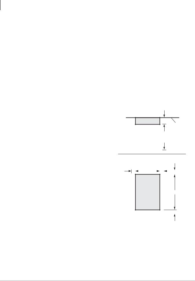
CTX28 Installation
Site Requirements
Site Requirements
This section defines the installation site requirements necessary to ensure a proper operating environment for the CTX28. Also included are grounding requirements.
Input Power
The system requires an input power source of 115VAC ± 10VAC, 50/60 Hz, 1.5 amps. The AC outlet is recommended to be dedicated and unswitched. (See “AC Power and Grounding Requirements” on page 1-4.)
This eliminates interference from branch circuit motor noise or the like, and to prevent accidental power-off. To avoid accidental power turn-off, Toshiba recommends that you do not use an On/Off wall switch on this dedicated AC circuit.
For the Strata CTX28, a reserve power source (HPFB-6) may be connected to the system to serve as a power failure backup (See Step 8 on page 1-18).
Clearance and Location
The minimum clearance requirements for the Strata CTX28 Base cabinet is shown in Figure 1-1. Refer to Figure 1-5 on page 1-7 for CTX28 KSU mounting instructions.
Consider the following conditions when selecting a location for the KSU(s):
The location must be:
•Dry and clean
•Well ventilated
•Well illuminated
•Easily accessible
The location must not be:
•Subject to extreme heat or cold
•Subject to corrosive fumes, dust, or other airborne contaminants
•Subject to excessive vibration
•Next to television, radio, office automation, or high frequency equipment
If reserve power (HPFB-6) is to be installed for the Strata CTX28, the batteries will require a well-ventilated location close to the CHSU28A.
Top View
3.5" Wall
3 Feet
Front View
2" |
|
|
12.25" |
|
2" |
|
|
|
|
|
|
|
|
|
|||||
|
|
|
|
|
|
2" |
|||
CTX28
Base KSU
18"
7062 |
2" |
|
|
Figure 1-1 CTX28 Base KSU Clearance
Requirements
1-2 |
Strata CTX I&M 06/04 |

CTX28 Installation
Site Requirements
Table 1-1 provides a summary of the electrical and environmental characteristics.
Table 1-1 Summary of Electrical/Environmental Characteristics
|
CTX28 Primary Power |
|
Input AC (Power Supply Specification) |
|
100~240VAC |
AC frequency |
|
50/60 Hz |
Power |
|
CTX28 - 100 watts maximum |
AC input current |
|
1.5A maximum |
|
|
|
Environmental Specifications |
||
Operating temperature |
|
32~104¡ F (0 ~40¡ C) |
Operating humidity |
|
20~80% relative humidity without condensation |
Storage temperature |
|
-4~140¡ F (-20~60¡ C) |
|
|
|
|
|
Power |
Input DC |
|
15V to use the factory-shipped AC adapter |
|
|
|
|
Power Converter |
|
DC voltage output specification |
|
-24VDC (-26.3~-28.3VDC) |
|
+5VDC (+4.5~+5.5VDC) |
|
|
|
|
|
|
|
Standard Telephone Ring Circuit (GMAU and GSTU) |
||
Ring Voltage |
|
180V p-p square wave |
|
|
|
Ringing capability |
|
1 REN, 1 circuit - one telephone per circuit |
|
|
|
Installation CTX28
Strata CTX I&M 06/04 |
1-3 |

CTX28 Installation
AC Power and Grounding Requirements
AC Power and Grounding Requirements
The CTX28 requires a solid earth ground for proper operation. The AC power cord connects to a standard AC power outlet. The ground for the CTX28 must originate at the building’s main power distribution panel and have a solid connection to earth ground. (See Figure 1-2.)
P10 Wire Connector
to HPFBG Battery Connector
TB1 to HPFB6 FG (#10 AWG Wire)
AC Adapter Cord plugs into GMAS
CTX28 Cabinet
TB2
TB3  on GMAU
Dealer-supplied wire (#10 AWG gauge or larger to pass ground specification test)
Grounding Rod
or
Electrical Building
Ground (Main Power
Distribution Box)
7126
AC Voltage 90VAC ± 264VAC
AC Current 1.5 amps max.
Figure 1-2 Ground to AC Power Cord
CAUTION! Lack of proper ground may cause improper operation and, in extreme cases, system failure.
WARNING! Failure to provide a proper ground may be a safety hazard to service personnel or lead to confusing trouble symptoms, such as noise on the talk path including GVMU greetings and messages. In extreme cases, system failure may result because the system is not properly protected from lightning or power transients.
1-4 |
Strata CTX I&M 06/04 |

CTX28 Installation
AC Power and Grounding Requirements
AC Power Ground Test
Test the “wire ground” for continuity by either measuring the resistance between the TB3 terminal (earth ground) on the GMAU and a metal cold water pipe (maximum: 1 ohm), or by using a commercially available earth ground indicator. If neither procedure is possible, perform the following earth ground test procedure.
WARNING! Hazardous voltages that may cause death or injury are exposed during the following test. Use great care when working with AC power line voltage.
To perform the earth ground test procedure
1.Obtain a suitable voltmeter, and set it for a possible reading of up to 250VAC.
2.Connect the meter probes between the two main AC voltage terminals (white and black wires) on the wall outlet. The reading obtained should be between 100~125VAC.
3.Move one of the meter probes to TB3 terminal (green wire ground). Either the same reading or a reading of zero volts should be obtained.
4.If the reading is zero volts, leave one probe on the ground terminal and move the other probe to the second voltage terminal.
CAUTION! If a reading of zero volts is obtained on both voltage terminals (white wire to TB3 wire, black wire to TB3 wire), the outlet is not properly grounded. Omit Steps 5 and 6, and see following CAUTION!
5.If a reading of zero volts on one terminal, and a reading of 100~125VAC on the other terminal is obtained, remove both probes from the outlet.
6.Set the meter to the “OHMS/Rx1” scale. Place one probe on the TB3 ground terminal, and the other probe on the terminal that produced a reading of zero volts. The reading should be less than one ohm.
CAUTION! If the reading is more than one ohm, then the outlet is not adequately grounded. If the above tests show the outlet AC voltage is not in range or is not properly grounded, the condition should be corrected (per Article 250 of the National Electrical Code) by a qualified electrician before the system is connected.
Installation CTX28
Table 1-2 Grounding Wiring Summary
Grounding Requirement |
From |
To |
Description |
System connects to earth ground |
Earth ground |
TB3 on GMAU |
|
|
|
|
|
FG of HPFB-6 connect to GMAU |
HPFB-6 FG Screw |
TB1 on GMAU |
|
|
|
|
Less than 1 ohm |
HPFB-6 Ground Feed |
TB1 on GMAU |
TB3 on GMAU |
|
|
|
|
|
GETS connects green ground wire to |
GETS ground wire |
TB2 on GMAU |
|
GMAU |
|
||
|
|
|
|
|
|
|
|
Strata CTX I&M 06/04 |
1-5 |
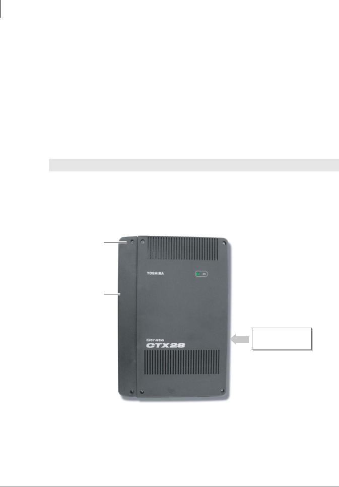
CTX28 Installation
Installing the CTX28 Cabinet
Installing the CTX28 Cabinet
Check the items shipped.
•CHSU28A cabinet
•GCTU1A processor PCB
•AC adapter
•Tie wrap for cable clamp
•Tie wrap for AC adapter
•Velcro strap for AC adapter cord
Step 1: Mount the Cabinet on the Wall
The Base cabinet is designed to be mounted on a wall or other vertical surface.
WARNING! To prevent electrical shock, make sure the power supply switch is turned Off.
To mount the Base KSU
1.Make sure the location for the CTX28 meets the minimum clearance requirements specified in Figure 1-1 on page 1-2.
2.Loosen the screws on the front cover and the side cover of the Base KSU, remove the covers (see Figure 1-3).
Cover
Screws (6)
Side Cover
 = Six cover screws to be removed before mounting KSU
 DC Power LED
 Base Cover
Model: CHSU28A
Strata CTX28
Label on edge of
Base KSU
7125a
Figure 1-3 CTX28 Cabinet Exterior
1-6 |
Strata CTX I&M 06/04 |
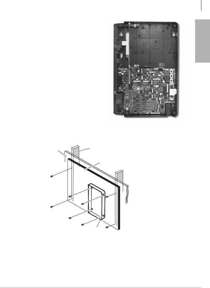
3.Place the Base KSU on the desired location on the mounting surface and mark the location of the four screw holes. See Figures 1-4 and 1-5.
4.Using a hard board between the KSU and the wall, secure the hard board to the wall first, making certain that screws are aligned with studs. See Figure 1-5.
5.Drill holes on these marks and secure screws approximately two thirds of the way into the top two holes on the mounting surface.
6.Hang the unit from the top two screws and then secure the top screws completely into the mounting surface.
7.Finish securing the unit to the mounting surface by completely screwing the bottom two screws into the wall.
CTX28 Installation
Installing the CTX28 Cabinet
Installation CTX28
7104
Figure 1-4 CTX28 Base KSU Interior
Plaster |
Method 2 |
Stud |
|
Board |
|
Hard Board
(1/2 Inch Plywood)
Base KSU
7114
Figure 1-5 KSU Wall Mounting
8. Ground system according to “AC Power and Grounding Requirements” on page 1-4.
Strata CTX I&M 06/04 |
1-7 |

CTX28 Installation
Installing the CTX28 Cabinet
PCB Installation
Overview Instructions
The following is an overview for installing the Printed Circuit Boards (PCBs) into the Strata CTX28. After reading this section, proceed to the step-by-step instructions for each PCB.
1.Apply proper settings on the GMAU1A (motherboard Figure 1-7).
2.If applicable, set SW6 battery jumper to ON and install the GVMU1A Voice Mail card (Figures 1-8 and 1-9).
3.Set P601 battery jumper to ON and install the GCTU1A (processor Figures 1-6 and 1-10).
4.If applicable, install the GCDU1A (3 CO, 3 CLID and 8 DKT circuits Figure 1-11).
5.If applicable, install GSTU1A (standard telephone interface Figure 1-12).
6.If applicable, install the GETS1A 100Base-TX I/F PCB (Figure 1-13).
7.If applicable, install the BSIS1A for SMDR (Figure 1-6).
8.If applicable, install HPFB-6 battery/charger (Figure 1-14).
9.Connect wiring (Table 1-14).
10.Connect AC Adaptor to P2 of the CTX28 sub-motherboard (GMAS, Figures 1-15 and 1-16) and plug the AC Adaptor into AC power.
11.Turn the System ON by sliding the SW1 ON/OFF switch down. The ON/OFF LED located by STANDBY will turn on (Figure 1-15).
PCB Descriptions
This describes the CTX28 cabinet PCBs (see Table 1-3 and Figure 1-6.)
Table 1-3 CTX28 (CHSU28) Cabinet circuit cards
Part |
Title |
Description |
|
GMAU1A |
Main Motherboard |
The GMAU motherboard supports 3 CO lines, 3 CLIDs, |
|
|
|
8 Digital Telephones, 1 Standard Telephone. The |
|
|
|
||
GMAS1A |
Sub-motherboard |
GCTU, GVMU, and AC power adaptor plugs into the |
|
|
|
GMAS sub-motherboard dedicated slots. |
|
|
|
|
|
GCTU1A |
Processor |
Shipped with cabinet. |
|
|
|
|
|
GVMU1A |
Voice Mail Circuit Card |
(Optional) Voice Mail. |
|
|
|
|
|
GCDU1A |
CO, CLID, DKT circuit |
(Optional) Supports 3 CO lines, 3 CLIDs, 8 Digital |
|
card |
Telephones. The GCDU1A plugs onto the motherboard. |
||
|
|||
|
|
|
|
GSTU1A |
Standard Telephone |
(Optional) Provides 1 Standard Telephone port. |
|
Circuit Card |
|||
|
|
||
|
|
|
|
GETS1A |
100BaseT I/F |
(Optional) Ethernet 100Base T cable.(optional) |
|
|
|
|
|
BSIS1A |
RS232C |
(Optional) RS232-C. Provides 4 serial I/O ports. |
|
|
|
|
|
HPFB6 |
External Battery |
(Optional) Provides backup Reserve power. |
|
|
|
|
1-8 |
Strata CTX I&M 06/04 |

CTX28 Installation
Installing the CTX28 Cabinet
BSIS (RS232-C)
SmartMedia Card
GCTU (Processor)
GVMU (Voice Mail) installs beneath the GCTU
GETS (100Base TX)
GSTU (Standard Telephone)
GMAU (Main Motherboard)
GCDU
(CO, CLID, DKT)
Installation CTX28
7108
Figure 1-6 CTX28 Interior with PCBs
Strata CTX I&M 06/04 |
1-9 |

CTX28 Installation
Installing the CTX28 Cabinet
Step 1: Set Jumpers on the GMAU1A (Motherboard)
The GMAU1A (shown in Figure 1-7) supports up to 6 CO lines with Caller ID (CLID).
|
SW1 |
SW1 |
||||
|
|
|
|
|
ON/OFF |
|
ON |
|
|
|
STANDBY |
||
|
|
|
|
|
|
(Standby) |
|
|
|
|
|
|
|
P5
P6
P8
P7
P4
TB2
CO1
TB3
CO2
CO3
SW400 (3db/0DB)
SW500 (3db/0DB)
SW600 (3db/0DB)
|
|
7113 |
|
|
|
|
|
|
|
|
|
|
|
|
|
||
|
|
|
|
|
|
|
||
|
|
|
|
|
|
|
||
Figure 1-7 GMAU PCB |
|
|
|
|
|
|
|
|
Table 1-4 GMAU Controls, Switches and Indicators |
|
|
|
|
|
|
||
|
|
|
|
|
|
|
|
|
Control/Indicator/Connector |
Type of Component |
Description |
||||||
|
|
Power Switch: |
||||||
SW1 |
2-position slide switch |
[STANDBY] = no DC power supply. |
||||||
[ON] = DC voltage supplied. [ON] activates the |
||||||||
|
|
|||||||
|
|
reserve power from HPFB-6 battery pack. |
||||||
|
|
|
|
|
|
|
|
|
SW400 |
|
|
|
|
|
|
|
|
|
|
|
|
|
|
|
|
|
SW500 |
2-position slide switch |
3dB Pad switch |
||||||
|
|
|
|
|
|
|
|
|
SW600 |
|
|
|
|
|
|
|
|
|
|
|
|
|
|
|
|
|
|
|
Power indicator; when SW1 is [ON], turned on. |
||||||
CD6 |
LED |
Red both AC power and 3Reserve power. SW1 |
||||||
|
|
is [STANDBY], turned off. |
||||||
|
|
|
|
|
|
|
|
|
TB1 |
Plate with screw |
Grounding for HPFB-6 external battery |
||||||
|
|
|
|
|
|
|
|
|
TB2 |
Plate with screw |
Grounding for GETS Ethernet card |
||||||
|
|
|
|
|
|
|
|
|
TB3 |
Plate with screw |
Grounding for CTX28 system, connect to earth |
||||||
ground |
||||||||
|
|
|||||||
|
|
|
|
|
|
|
|
|
P1 |
50-pin Amphenol |
DKT, SLT and Power Failure Transfer interface |
||||||
connector |
||||||||
|
|
|
|
|
|
|
||
|
|
|
|
|
|
|
|
|
P3 |
44-pin DIN connector |
GMAS interface |
||||||
|
|
|
|
|
|
|
|
|
1-10 |
Strata CTX I&M 06/04 |
Loading...