


 Loading...
USB Protocol Suite
User Manual
Software Version 4.75
Document Version 4.75
September 2013
Trademarks and Servicemarks
CATC, Teledyne LeCroy Voyager, Voyager ReadyLink, USB Protocol Suite, USB Advisor, Advisor T3, Mercury T2, USB Chief, USB Inspector, USB Detective, USB Tracer/Trainer, and BusEngine are trademarks of Teledyne LeCroy.
Microsoft and Windows are registered trademarks of Microsoft Corporation. Intel and Pentium are registered trademarks of Intel Corporation.
All other trademarks and registered trademarks are property of their respective owners.
THE SPECIFICATIONS AND INFORMATION REGARDING THE PRODUCTS IN THIS MANUAL ARE SUBJECT TO CHANGE WITHOUT NOTICE. ALL INFORMATION, EXAMPLES AND RECOMMENDATIONS IN THIS MANUAL ARE BELIEVED TO BE ACCURATE BUT ARE REPRESENTED WITHOUT WARRANTY OF ANY KIND, EXPRESS OR IMPLIED. USERS ARE FULLY RESPONSIBLE FOR THEIR APPLICATION OF ANY PRODUCTS.
THE SOFTWARE LICENSE AND LIMITED WARRANTY FOR THE ACCOMPANYING PRODUCT ARE SET FORTH IN INFORMATION THAT SHIPPED WITH THE PRODUCT AND ARE INCORPORATED HEREIN BY THIS REFERENCE. IF YOU ARE UNABLE TO LOCATE THE SOFTWARE LICENSE OR LIMITED WARRANTY, CONTACT Teledyne LeCroy FOR A COPY.
© 2008 Teledyne LeCroy, Inc; All rights reserved.
This document may be printed and reproduced without additional permission, but all copies should contain this copyright notice.
WEEE Program
Teledyne LeCroy
3385 Scott Blvd.
Santa Clara, CA 95054
TEL: 800 909 7112 (USA and Canada)
TEL: 408 653 1260 (worldwide)
USB Protocol Suite User Manual |
2 |

Contents
Chapter 1: Overview............................................................................................... |
17 |
1.1 Common Features .................................................................................................................. |
17 |
1.1.1 Graphical Bus Traffic Display ..................................................................................................................... |
17 |
1.1.2 Accurate Time Measurement (Voyager, Advisor T3) ................................................................................ |
18 |
1.1.3 CrossSync Control Panel (Voyager, Advisor T3)...................................................................................... |
18 |
1.1.4 Comprehensive Error Detection and Analysis.......................................................................................... |
18 |
1.1.5 Real-Time Event Triggering and Capture Filtering ................................................................................... |
19 |
1.1.6 BusEngine Technology ............................................................................................................................... |
19 |
1.2 Voyager M3/M3i Analyzer....................................................................................................... |
20 |
1.2.1 USB 2.0 and USB 3.0 Features.................................................................................................................... |
20 |
1.2.2 General Description ..................................................................................................................................... |
21 |
1.2.3 Features ........................................................................................................................................................ |
22 |
General ........................................................................................................................................................................... |
22 |
Flexible 3.0 Calibration.................................................................................................................................................. |
23 |
Physical Components ................................................................................................................................................... |
23 |
Recording Options ........................................................................................................................................................ |
23 |
Display Options ............................................................................................................................................................. |
23 |
1.2.4 Hi-Speed Slow Clock ................................................................................................................................... |
24 |
1.2.5 Traffic Generation ........................................................................................................................................ |
24 |
ReadyLink™ Emulation................................................................................................................................................. |
25 |
1.2.6 Notes on LFPS Signals................................................................................................................................ |
25 |
1.3 Advisor T3 ............................................................................................................................... |
26 |
1.3.1 General Description ..................................................................................................................................... |
26 |
1.3.2 Features ........................................................................................................................................................ |
27 |
General ........................................................................................................................................................................... |
27 |
Flexible 3.0 Calibration.................................................................................................................................................. |
27 |
Physical Components ................................................................................................................................................... |
27 |
Recording Options ........................................................................................................................................................ |
28 |
Display Options ............................................................................................................................................................. |
28 |
1.4 Mercury T2............................................................................................................................... |
30 |
1.4.1 General Description ..................................................................................................................................... |
30 |
1.4.2 Features ........................................................................................................................................................ |
31 |
General ........................................................................................................................................................................... |
31 |
Physical Components ................................................................................................................................................... |
31 |
Recording Options ........................................................................................................................................................ |
31 |
Display Options ............................................................................................................................................................. |
32 |
USB Protocol Suite User Manual |
3 |

Teledyne LeCroy Corporation |
Contents |
1.5 Voyager M3x Analyzer............................................................................................................ |
33 |
1.5.1 USB 2.0 and USB 3.0 Features ................................................................................................................... |
33 |
1.5.2 General Description..................................................................................................................................... |
34 |
1.5.3 Features ........................................................................................................................................................ |
35 |
General ........................................................................................................................................................................... |
35 |
Flexible 3.0 Calibration.................................................................................................................................................. |
35 |
Physical Components ................................................................................................................................................... |
35 |
Recording Options ........................................................................................................................................................ |
35 |
Display Options ............................................................................................................................................................. |
36 |
1.5.4 Traffic Generation ........................................................................................................................................ |
37 |
ReadyLink™ Emulation................................................................................................................................................. |
37 |
1.5.5 Notes on LFPS Signals................................................................................................................................ |
38 |
1.6 USBTracer/Trainer, USB Advisor, USBMobile HS and USBMobile T2 ............................... |
38 |
Chapter 2: General Description ............................................................................ |
39 |
2.1 Voyager M3/M3i Analyzer....................................................................................................... |
39 |
2.1.1 System Components and Packing List...................................................................................................... |
39 |
2.1.2 Host Machine Requirements....................................................................................................................... |
39 |
2.1.3 Analyzer ........................................................................................................................................................ |
39 |
2.1.4 Specifications............................................................................................................................................... |
42 |
Power Requirements..................................................................................................................................................... |
42 |
Environmental Conditions ............................................................................................................................................ |
42 |
Probing Characteristics ................................................................................................................................................ |
42 |
Switches ......................................................................................................................................................................... |
42 |
Recording Memory Size................................................................................................................................................ |
42 |
2.2 Advisor T3 ............................................................................................................................... |
43 |
2.2.1 Components ................................................................................................................................................. |
43 |
2.2.2 Front Panel ................................................................................................................................................... |
43 |
2.2.3 Rear Panel .................................................................................................................................................... |
44 |
2.2.4 Advisor T3 System Setup............................................................................................................................ |
45 |
2.3 Mercury T2............................................................................................................................... |
46 |
2.3.1 Components ................................................................................................................................................. |
46 |
2.3.2 Front Panel ................................................................................................................................................... |
46 |
2.3.3 Rear Panel .................................................................................................................................................... |
47 |
2.3.4 Mercury T2 System Setup ........................................................................................................................... |
48 |
2.4 Voyager M3x Analyzer............................................................................................................ |
49 |
2.4.1 System Components and Packing List...................................................................................................... |
49 |
2.4.2 Host Machine Requirements....................................................................................................................... |
49 |
2.4.3 Analyzer ........................................................................................................................................................ |
49 |
2.4.4 Specifications............................................................................................................................................... |
51 |
Power Requirements..................................................................................................................................................... |
51 |
Environmental Conditions ............................................................................................................................................ |
52 |
Probing Characteristics ................................................................................................................................................ |
52 |
Switches ......................................................................................................................................................................... |
52 |
Recording Memory Size................................................................................................................................................ |
52 |
2.5 USBTracer/Trainer, USB Advisor, USBMobile HS and USBMobile T2 ............................... |
53 |
4 |
USB Protocol Suite User Manual |

Contents |
Teledyne LeCroy Corporation |
||
Chapter 3: Installation............................................................................................ |
|
55 |
|
3.1 |
Installing the Analyzer Software on the Host Machine ....................................................... |
|
55 |
3.2 |
Setting Up the Analyzer - USB Connection.......................................................................... |
|
55 |
3.3 |
Setting Up the Analyzer - Ethernet Connection................................................................... |
|
56 |
3.4 Cascading with CATC SYNC Expansion Card ..................................................................... |
|
57 |
|
|
3.4.1 Capturing USB 2.0 traffic with CATC Sync or Cross Sync ...................................................................... |
|
57 |
|
3.4.2 Removing Expansion Cards ....................................................................................................................... |
|
58 |
3.5 |
Application Startup................................................................................................................. |
|
60 |
|
3.5.1 Confirm Proper Hardware Installation and USB or Ethernet Connection .............................................. |
|
61 |
|
USB Connection ............................................................................................................................................................ |
|
61 |
|
Ethernet Connection (Voyager only) ........................................................................................................................... |
|
61 |
|
3.5.2 Analyzer Devices ......................................................................................................................................... |
|
62 |
|
3.5.3 IP Settings (Voyager only) .......................................................................................................................... |
|
63 |
|
3.5.4 Analyzer Network......................................................................................................................................... |
|
64 |
|
3.5.5 USB 3.0 Device/Host Signal Parameters (Voyager M3, M3i, Advisor T3 and M3x) |
................................ 65 |
|
|
Input Equalization.......................................................................................................................................................... |
|
67 |
|
3.5.6 USB 3.0 Cabling and Signal Integrity......................................................................................................... |
|
68 |
3.6 |
Your First USB Recording...................................................................................................... |
|
68 |
|
3.6.1 Trace View Features .................................................................................................................................... |
|
70 |
3.7 |
Notes on Windows 7 and Windows 8 Directory Protections.............................................. |
|
71 |
|
3.7.1 User Data File Paths .................................................................................................................................... |
|
71 |
3.8 |
Notes on Windows Sleep and Hibernation Features........................................................... |
|
71 |
Chapter 4: Software Overview................................................................................ |
|
73 |
|
4.1 |
Starting the Program .............................................................................................................. |
|
73 |
4.2 The Main Display Window...................................................................................................... |
|
74 |
|
|
4.2.1 Exports to .CSV............................................................................................................................................ |
|
81 |
|
Export Packets to .CSV................................................................................................................................................. |
|
81 |
|
Export Transactions to .CSV ........................................................................................................................................ |
|
81 |
|
Export Spreadsheet View to .CSV................................................................................................................................ |
|
81 |
|
4.2.2 Exporting Packets to USB 2.0 Host Traffic Generator Text File (.utg files)............................................ |
|
81 |
4.3 |
Tool Bar ................................................................................................................................... |
|
83 |
|
4.3.1 Files, Searches, and Options...................................................................................................................... |
|
83 |
|
4.3.2 Zoom and Wrap............................................................................................................................................ |
|
84 |
|
4.3.3 Miscellaneous .............................................................................................................................................. |
|
84 |
|
4.3.4 Analysis (Reports) ...................................................................................................................................... |
|
84 |
|
4.3.5 Recording ..................................................................................................................................................... |
|
86 |
|
4.3.6 Generator (Traffic Generation for USB 3) .................................................................................................. |
|
86 |
|
4.3.7 Generator (Traffic Generation for USB 2) .................................................................................................. |
|
87 |
|
4.3.8 View Level..................................................................................................................................................... |
|
87 |
|
4.3.9 Trace Views .................................................................................................................................................. |
|
87 |
|
USB 2.0 USB 3.0 Show ................................................................................................................................................. |
|
88 |
|
Hiding Traffic (2.0 & 3.0)................................................................................................................................................ |
|
88 |
USB Protocol Suite User Manual |
5 |

Teledyne LeCroy Corporation Contents
4.4 |
Tooltips .................................................................................................................................... |
91 |
4.5 |
View Options ........................................................................................................................... |
92 |
|
4.5.1 Resetting the Toolbar .................................................................................................................................. |
92 |
4.6 |
Status Bar................................................................................................................................ |
93 |
|
4.6.1 Recording Progress..................................................................................................................................... |
93 |
|
4.6.2 Recording Status ......................................................................................................................................... |
94 |
|
4.6.3 Recording Activity ....................................................................................................................................... |
96 |
|
4.6.4 Search Status ............................................................................................................................................... |
96 |
|
4.6.5 SuperSpeed Termination Status ................................................................................................................ |
96 |
|
4.6.6 Link Status.................................................................................................................................................... |
97 |
4.7 |
Navigation Tools ..................................................................................................................... |
98 |
|
4.7.1 Zoom In ......................................................................................................................................................... |
98 |
|
4.7.2 Zoom Out ...................................................................................................................................................... |
98 |
|
4.7.3 Wrap .............................................................................................................................................................. |
98 |
4.8 |
CrossSync Control Panel....................................................................................................... |
98 |
|
4.8.1 Launching the CrossSync Control Panel .................................................................................................. |
98 |
4.9 |
Analyzer Keyboard Shortcuts ............................................................................................. |
100 |
Chapter 5: Reading a Trace................................................................................. |
103 |
5.1 Trace View Features ............................................................................................................. |
103 |
5.1.1 Anchor Points - Synchronized Views....................................................................................................... |
104 |
5.1.2 USB 3.0 Packets......................................................................................................................................... |
105 |
5.1.3 Packet Direction......................................................................................................................................... |
106 |
5.2 Markers.................................................................................................................................. |
106 |
5.2.1 Markers Overview ...................................................................................................................................... |
106 |
5.2.2 Functionality of Markers ........................................................................................................................... |
106 |
5.2.3 Attaching Markers...................................................................................................................................... |
108 |
5.2.4 Adding an Attachment............................................................................................................................... |
108 |
5.2.5 Recording an Audio File............................................................................................................................ |
109 |
5.2.6 Video Files supported ............................................................................................................................... |
109 |
5.2.7 Attachment Types and Visualization........................................................................................................ |
110 |
5.2.8 Embedded Attachments to a Marker........................................................................................................ |
110 |
5.2.9 Viewing Attachments of a Marker ............................................................................................................ |
110 |
Text ............................................................................................................................................................................... |
111 |
Audio............................................................................................................................................................................. |
112 |
Video............................................................................................................................................................................. |
113 |
File Attachment............................................................................................................................................................ |
113 |
URL Link....................................................................................................................................................................... |
113 |
YouTube Video............................................................................................................................................................. |
114 |
Images .......................................................................................................................................................................... |
114 |
Other Attachments ...................................................................................................................................................... |
114 |
5.2.10 Edit Marker ............................................................................................................................................... |
115 |
5.2.11 All Markers Window................................................................................................................................. |
116 |
5.3 CATC Walk Playlist ............................................................................................................... |
117 |
5.3.1 Playlist Functionality ................................................................................................................................. |
118 |
6 |
USB Protocol Suite User Manual |

Contents |
Teledyne LeCroy Corporation |
|
5.3.2 Playback Window....................................................................................................................................... |
119 |
|
|
Playlist Playback Controls.......................................................................................................................................... |
120 |
5.4 Time Stamp............................................................................................................................ |
121 |
|
5.5 View Raw Bits (2.0) ............................................................................................................... |
122 |
|
5.6 Expanding and Collapsing Data Fields............................................................................... |
123 |
|
5.6.1 Using the Expand/Collapse Data Field Arrows ....................................................................................... |
123 |
|
5.6.2 Double-Clicking to Expand/Collapse Data Fields ................................................................................... |
123 |
|
5.6.3 Expanding or Collapsing All Data Fields................................................................................................. |
124 |
|
5.6.4 Using the Data Field Pop-up Menus......................................................................................................... |
124 |
|
|
Expand or Collapse All Data Fields ........................................................................................................................... |
125 |
5.7 Format/Color/Hide Fields..................................................................................................... |
125 |
|
5.7.1 Hide/Show Field when Packet Section is Collapsed .............................................................................. |
125 |
|
5.8 View Data Block .................................................................................................................... |
126 |
|
5.9 Pop-up Tool-tips ................................................................................................................... |
127 |
|
5.10 |
Stacking............................................................................................................................... |
127 |
5.11 Display 2 Only ..................................................................................................................... |
128 |
|
5.12 |
Display 3 Only..................................................................................................................... |
129 |
5.13 |
Hiding Items Indicators...................................................................................................... |
129 |
5.14 |
Hide Devices ....................................................................................................................... |
129 |
5.15 |
Hide All Packets Except Transfers Packets. .................................................................... |
129 |
5.16 Hide NAKs ........................................................................................................................... |
129 |
|
5.17 |
Hide SOF Packets (2.0)....................................................................................................... |
130 |
5.18 |
Hide Chirps (2.0) ................................................................................................................. |
130 |
5.19 |
Hide Upstream Packets (3.0).............................................................................................. |
130 |
5.20 |
Hide Downstream Packets (3.0) ........................................................................................ |
130 |
5.21 |
Hide Link Training Sequences (3.0) .................................................................................. |
130 |
5.22 |
Hide Link Commands (Flow Control) (3.0) ....................................................................... |
130 |
5.23 |
Hide Bus Events (3.0) ......................................................................................................... |
131 |
5.24 |
Hide Miscellaneous Packets (3.0) ..................................................................................... |
131 |
5.25 |
Hide All Transactions Except Stream Id Numbers .......................................................... |
131 |
5.26 |
Switch to Transactions View ............................................................................................. |
133 |
5.27 |
View Decoded Transactions .............................................................................................. |
134 |
5.27.1 Expanded and Collapsed Transactions................................................................................................. |
135 |
|
5.28 |
Switch to Split Transaction View....................................................................................... |
136 |
5.29 |
Switch to Transfer View ..................................................................................................... |
136 |
5.30 |
View Decoded Transfers .................................................................................................... |
137 |
5.30.1 Expanded and Collapsed Transfers....................................................................................................... |
138 |
|
5.31 |
Decoding Protocol-Specific Fields in Transactions and Transfers ............................... |
139 |
5.32 |
Switch to PTP Transactions............................................................................................... |
139 |
5.33 |
Switch to PTP Object Transfers ........................................................................................ |
139 |
5.34 |
Switch to PTP Sessions..................................................................................................... |
140 |
USB Protocol Suite User Manual |
7 |

Teledyne LeCroy Corporation |
Contents |
5.35 Switch to SCSI Operations ................................................................................................ |
141 |
5.35.1 SCSI Metrics ............................................................................................................................................. |
141 |
5.36 Compressed CATC Trace View.......................................................................................... |
141 |
5.37 Spreadsheet View ............................................................................................................... |
142 |
5.37.1 Columns.................................................................................................................................................... |
144 |
5.37.2 Rows ......................................................................................................................................................... |
144 |
5.37.3 Detail View and Spreadsheet View......................................................................................................... |
146 |
5.38 Edit Comment ..................................................................................................................... |
147 |
Chapter 6: Searching Traces............................................................................... |
149 |
6.1 Go to Trigger ......................................................................................................................... |
149 |
6.2 Go to Selected Packet.......................................................................................................... |
150 |
6.3 Go to Packet/Transaction/Transfer ..................................................................................... |
150 |
6.4 Go to Marker.......................................................................................................................... |
150 |
6.5 Go To USB 2.0 ....................................................................................................................... |
151 |
6.5.1 Packet IDs (PIDs) ....................................................................................................................................... |
152 |
6.5.2 ANY Error.................................................................................................................................................... |
152 |
6.5.3 Errors .......................................................................................................................................................... |
152 |
6.5.4 Data Length ................................................................................................................................................ |
153 |
6.5.5 Addr & Endp ............................................................................................................................................... |
154 |
6.5.6 Bus Conditions .......................................................................................................................................... |
154 |
6.5.7 Split HubAddr & Port ................................................................................................................................. |
155 |
6.5.8 On-the-Go ................................................................................................................................................... |
155 |
6.5.9 Transfer Standard Request Type ............................................................................................................. |
156 |
6.5.10 Transfer Type ........................................................................................................................................... |
157 |
6.6 Go To USB3.0 ........................................................................................................................ |
158 |
6.6.1 Packet Type ................................................................................................................................................ |
159 |
6.6.2 LFPS Type .................................................................................................................................................. |
160 |
6.6.3 Deferred Packet.......................................................................................................................................... |
161 |
6.6.4 ANY Error161 |
|
6.6.5 Specific Errors ........................................................................................................................................... |
162 |
6.6.6 Data Length ................................................................................................................................................ |
163 |
6.6.7 Address and Endpoint............................................................................................................................... |
164 |
6.6.8 Header Packet Type................................................................................................................................... |
164 |
6.6.9 Link Command ........................................................................................................................................... |
165 |
6.6.10 LMP Subtype ............................................................................................................................................ |
166 |
6.6.11 Transaction Packet Type......................................................................................................................... |
167 |
6.6.12 Transfer Standard Request Type ........................................................................................................... |
168 |
6.6.13 Transfer Type ........................................................................................................................................... |
169 |
6.6.14 Go To Channel ......................................................................................................................................... |
170 |
6.7 Go To SCSI ............................................................................................................................ |
170 |
6.7.1 Error ............................................................................................................................................................ |
170 |
8 |
USB Protocol Suite User Manual |

Contents |
Teledyne LeCroy Corporation |
|
6.8 |
Find ........................................................................................................................................ |
171 |
|
6.8.1 Data Pattern Mask and Match ................................................................................................................... |
173 |
6.9 |
Find Next ............................................................................................................................... |
174 |
6.10 Search Direction ................................................................................................................. |
174 |
|
6.11 Protocol ............................................................................................................................... |
174 |
|
Chapter 7: Display Options ................................................................................. |
175 |
|
7.1 |
General Display Options...................................................................................................... |
176 |
7.2 |
Color/Format/Hiding Display Options................................................................................. |
177 |
|
7.2.1 Color Display Options ............................................................................................................................... |
177 |
|
7.2.2 Formats Display Options .......................................................................................................................... |
179 |
|
7.2.3 Hiding Display Options ............................................................................................................................. |
180 |
7.3 |
USB 2.0 Packet Hiding Options........................................................................................... |
180 |
7.4 |
USB 3.0 Packet Hiding Options........................................................................................... |
181 |
7.5 |
Level Hiding Options............................................................................................................ |
182 |
7.6 |
Saving/Loading Display Options......................................................................................... |
183 |
7.7 |
Restore Factory Setting ....................................................................................................... |
184 |
Chapter 8: Decode Requests .............................................................................. |
185 |
|
8.1 |
Class and Vendor Definition Files....................................................................................... |
185 |
8.2 |
Class/Vendor Decoding Options......................................................................................... |
191 |
|
8.2.1 Mapping Request Recipient to Class/Vendor Decoding ........................................................................ |
191 |
|
8.2.2 Mapping Endpoint to Class/Vendor Decoding........................................................................................ |
193 |
8.3 |
General Options.................................................................................................................... |
199 |
|
8.3.1 Decoding USB Device Requests .............................................................................................................. |
199 |
|
8.3.2 Decoding Standard Requests................................................................................................................... |
200 |
|
8.3.3 Decoding Class Requests......................................................................................................................... |
201 |
|
8.3.4 Decoding Vendor Requests ...................................................................................................................... |
201 |
|
8.3.5 Decoding Undefined USB/WUSB Device Requests................................................................................ |
202 |
|
8.3.6 Decoding using Endpoint Information..................................................................................................... |
202 |
|
8.3.7 Changing the Layout of Decode Requests.............................................................................................. |
203 |
|
8.3.8 Decoded Fields View ................................................................................................................................. |
204 |
Chapter 9: Reports ............................................................................................... |
207 |
|
9.1 |
View Docking and Floating Windows. ................................................................................ |
208 |
9.2 |
Trace Information.................................................................................................................. |
210 |
9.3 Error Summary...................................................................................................................... |
214 |
|
|
9.3.1 USB 2.0 Errors............................................................................................................................................ |
214 |
|
9.3.2 USB 3.0 Errors............................................................................................................................................ |
216 |
9.4 |
Timing Calculations.............................................................................................................. |
218 |
USB Protocol Suite User Manual |
9 |

Teledyne LeCroy Corporation |
Contents |
9.5 Data View............................................................................................................................... |
221 |
9.6 Traffic Summary Report....................................................................................................... |
222 |
9.6.1 SCSI Metrics ............................................................................................................................................... |
223 |
9.7 Bus Utilization....................................................................................................................... |
224 |
9.7.1 Bus Utilization Buttons ............................................................................................................................. |
225 |
9.7.2 View Settings Menu ................................................................................................................................... |
226 |
9.7.3 Graph Areas Menu ..................................................................................................................................... |
228 |
Change the Properties in the Bus Utilization Graph ................................................................................................ |
229 |
Creating a New Bus Utilization Graph ....................................................................................................................... |
230 |
9.8 Link Tracker (3.0) .................................................................................................................. |
231 |
9.8.1 Using the Link Tracker Window ............................................................................................................... |
232 |
Zooming In and Out..................................................................................................................................................... |
232 |
Collapsing Idle Time, Enabling Tool tips, and Resetting Column Widths ............................................................. |
232 |
Docking and Undocking the Window ........................................................................................................................ |
233 |
Setting Markers............................................................................................................................................................ |
233 |
Hiding Traffic................................................................................................................................................................ |
233 |
9.8.2 Link Tracker Buttons ................................................................................................................................. |
234 |
9.9 Using the Navigator.............................................................................................................. |
235 |
9.9.1 Displaying the Navigator........................................................................................................................... |
236 |
9.9.2 Navigator Toolbar ...................................................................................................................................... |
237 |
9.9.3 Navigator Ranges ...................................................................................................................................... |
237 |
To Determine Current Position................................................................................................................................... |
238 |
To Reset Navigator Range.......................................................................................................................................... |
238 |
9.9.4 Navigator Panes......................................................................................................................................... |
239 |
To Show/Hide Navigator Panes.................................................................................................................................. |
239 |
Navigator Slider ........................................................................................................................................................... |
240 |
Navigator Legend ........................................................................................................................................................ |
240 |
Using the Legend to Show/Hide Navigator Panes.................................................................................................... |
241 |
Using the Legend to Set the Priority of Information Display................................................................................... |
241 |
9.10 Detail View........................................................................................................................... |
242 |
9.10.1 Detail View and Spreadsheet View......................................................................................................... |
242 |
9.11 Spec View (3.0).................................................................................................................... |
243 |
9.12 USB 3.0 Link State Timing View ........................................................................................ |
244 |
9.12.1 USB 3.0 Link State Timing View Toolbar ............................................................................................... |
244 |
9.12.2 USB 3.0 LTSSM View ............................................................................................................................... |
246 |
9.13 Power Tracker ..................................................................................................................... |
247 |
9.13.1 Power Tracker Toolbar ............................................................................................................................ |
248 |
9.13.2 Decoded Fields view................................................................................................................................ |
249 |
9.13.3 Running Verification Scripts................................................................................................................... |
249 |
9.14 Real Time Monitoring ......................................................................................................... |
253 |
9.14.1 Real-Time Statistics Buttons .................................................................................................................. |
254 |
9.14.2 Real-Time Statistical Monitor Pop-up Menu.......................................................................................... |
255 |
9.14.3 Displaying Multiple Graphs..................................................................................................................... |
256 |
10 |
USB Protocol Suite User Manual |
Contents |
Teledyne LeCroy Corporation |
Chapter 10: Recording Options .......................................................................... |
257 |
10.1 Recording Options Modes................................................................................................. |
258 |
10.2 General Recording Options............................................................................................... |
265 |
10.2.1 Product ..................................................................................................................................................... |
266 |
10.2.2 Trigger Mode ............................................................................................................................................ |
266 |
Snapshot ...................................................................................................................................................................... |
266 |
Manual Trigger............................................................................................................................................................. |
266 |
Event Trigger................................................................................................................................................................ |
267 |
10.2.3 Recording Channels (Voyager and Advisor T3).................................................................................... |
267 |
10.2.4 Recording Scope (Voyager, Advisor T3 and Mercury T2).................................................................... |
267 |
10.2.5 Buffer Size ................................................................................................................................................ |
268 |
10.2.6 Trigger Position ....................................................................................................................................... |
268 |
10.2.7 Options Name........................................................................................................................................... |
268 |
10.2.8 Trace File Name & Path ........................................................................................................................... |
269 |
10.2.9 VBus Power .............................................................................................................................................. |
270 |
10.2.10 CATC Sync (Voyager and AdvisorT3 only).......................................................................................... |
270 |
10.3 Recording Options-Misc. USB 2.0..................................................................................... |
270 |
10.3.1 Analyzer Trace Speed.............................................................................................................................. |
272 |
Notes on Hi Speed Recordings .................................................................................................................................. |
272 |
10.3.2 Generator/Analyzer Clocking Overrides................................................................................................ |
273 |
10.3.3 USB On-The-Go........................................................................................................................................ |
273 |
10.3.4 Generator-related Parameters ................................................................................................................ |
273 |
10.3.5 Data Truncation Option ........................................................................................................................... |
273 |
10.4 Recording Options - Misc. USB 3.0 for Voyager.............................................................. |
274 |
10.4.1 Very Slow Clock Usage (Voyager M3/M3i ONLY).................................................................................. |
277 |
External Clock Input Specifications........................................................................................................................... |
279 |
10.5 Recording Options - Misc. USB 3.0 for Advisor T3 ......................................................... |
280 |
10.6 Recording Rules Actions and Action Properties............................................................. |
281 |
10.7 Recording Rules - USB 2.0 ................................................................................................ |
283 |
10.7.1 Recording Rules Toolbar ........................................................................................................................ |
284 |
10.7.2 Recording Rules Page: How It Works.................................................................................................... |
286 |
10.7.3 Creating Event Buttons ........................................................................................................................... |
287 |
10.7.4 Dragging a Button to the Main Display Area......................................................................................... |
288 |
10.7.5 Assigning an Action ................................................................................................................................ |
289 |
10.7.6 Recording Rules Pop-Up Menus ............................................................................................................ |
290 |
Cell Pop-up Menu ........................................................................................................................................................ |
290 |
Action Pop-up Menu.................................................................................................................................................... |
290 |
Event Pop-up Menu ..................................................................................................................................................... |
291 |
10.7.7 Events and Event Properties for USB 2.0.............................................................................................. |
292 |
Event Properties (of the Error Event) ........................................................................................................................ |
293 |
Data Pattern Mask and Match..................................................................................................................................... |
294 |
10.7.8 Counters and Timers for USB 2.0........................................................................................................... |
296 |
Events and Actions ..................................................................................................................................................... |
296 |
Number of Analyzer Counters and Timers................................................................................................................ |
297 |
Packets ......................................................................................................................................................................... |
297 |
USB Protocol Suite User Manual |
11 |
Teledyne LeCroy Corporation |
Contents |
|
|
Using a Counter........................................................................................................................................................... |
297 |
Setting a Counter......................................................................................................................................................... |
298 |
Changing a Counter Value.......................................................................................................................................... |
298 |
10.7.9 Using a Single-State Sequence .............................................................................................................. |
298 |
10.7.10 Using a Multi-State Sequences............................................................................................................. |
298 |
10.7.11 Using Independent Sequences............................................................................................................. |
298 |
10.8 Recording Rules - USB 3.0 (Voyager/Advisor T3 only) ................................................... |
299 |
10.8.1 Recording Rules Toolbar ........................................................................................................................ |
300 |
10.8.2 Recording Rules Page: How It Works.................................................................................................... |
300 |
10.8.3 Creating Event Buttons ........................................................................................................................... |
300 |
10.8.4 Dragging a Button to the Main Display Area......................................................................................... |
302 |
10.8.5 Assigning an Action ................................................................................................................................ |
303 |
10.8.6 Recording Rules Pop-Up Menus ............................................................................................................ |
303 |
Cell Pop-up Menu ........................................................................................................................................................ |
303 |
Event Pop-up Menu ..................................................................................................................................................... |
303 |
Action Pop-up Menu.................................................................................................................................................... |
303 |
10.8.7 Actions and Action Properties ............................................................................................................... |
303 |
Action Properties......................................................................................................................................................... |
303 |
10.8.8 Events and Event Properties for USB 3.0.............................................................................................. |
304 |
10.8.9 Counters and Timers for USB 3.0........................................................................................................... |
308 |
10.8.10 Configuration Validity............................................................................................................................ |
310 |
10.9 Saving Recording Options................................................................................................. |
310 |
10.10 Recording Bus Data ......................................................................................................... |
310 |
10.11 Merging Trace Files .......................................................................................................... |
311 |
10.12 Recording Option Summary Tab..................................................................................... |
314 |
Chapter 11: Traffic Generation 2.0...................................................................... |
315 |
11.1 Connecting to Voyager M3/M3i.......................................................................................... |
315 |
Hi/Full/Low Speed Host Emulation ............................................................................................................................ |
315 |
Hi/Full/Low Speed Device Emulation......................................................................................................................... |
316 |
11.2 Connecting to Voyager M3x............................................................................................... |
317 |
Hi/Full/Low Speed Host Emulation ............................................................................................................................ |
317 |
Hi/Full/Low Speed Device Emulation......................................................................................................................... |
317 |
11.3 Traffic Generation Files...................................................................................................... |
318 |
11.4 Creating Traffic Generation Files ...................................................................................... |
318 |
11.4.1 Creating a Traffic Generation File with the Export Command............................................................. |
319 |
11.5 Editing a Generation File.................................................................................................... |
320 |
11.5.1 Toolbar...................................................................................................................................................... |
322 |
11.5.2 View Options Menu.................................................................................................................................. |
323 |
11.5.3 Pop-up Menu ............................................................................................................................................ |
323 |
11.5.4 File Tabs ................................................................................................................................................... |
324 |
11.5.5 Error Log................................................................................................................................................... |
324 |
11.5.6 Tooltips ..................................................................................................................................................... |
324 |
11.6 Loading the Generation File .............................................................................................. |
324 |
11.6.1 Traffic Generation Modes: Bitstream vs. Intelliframe........................................................................... |
327 |
12 |
USB Protocol Suite User Manual |
Contents |
Teledyne LeCroy Corporation |
|
|
|
|
11.7 Starting Traffic Generation................................................................................................. |
327 |
11.8 Repeating a Generation Session....................................................................................... |
327 |
11.9 Stop Traffic Generation ...................................................................................................... |
328 |
11.10 Device Emulation.............................................................................................................. |
328 |
11.10.1 Creating a Generation File .................................................................................................................... |
328 |
11.10.2 Setting Generation Options .................................................................................................................. |
328 |
11.10.3 Run the Traffic Generation Script File ................................................................................................. |
329 |
11.11 Voyager M3x USB 2.0 Script Limitations ........................................................................ |
329 |
11.12 Format of Traffic Generation Files .................................................................................. |
330 |
11.12.1 Script Control of Intelliframe vs Bitstream modes ............................................................................. |
331 |
Chapter 12: Traffic Generation 3.0 Exerciser .................................................... |
349 |
12.1 Connecting to Voyager M3/M3i.......................................................................................... |
349 |
12.1.1 Host Emulation......................................................................................................................................... |
349 |
12.1.2 Device Emulation ..................................................................................................................................... |
350 |
12.2 Connecting to Voyager M3x............................................................................................... |
350 |
12.2.1 Host Emulation......................................................................................................................................... |
350 |
12.2.2 Device Emulation ..................................................................................................................................... |
351 |
12.3 Transaction Engine............................................................................................................. |
351 |
12.4 Transaction Engine............................................................................................................. |
351 |
12.5 Exerciser Files .................................................................................................................... |
352 |
12.6 Creating Exerciser Files..................................................................................................... |
352 |
12.7 Exerciser Window............................................................................................................... |
352 |
12.7.1 Exerciser Menus ...................................................................................................................................... |
353 |
12.7.2 Main Exerciser Toolbar ........................................................................................................................... |
355 |
12.8 Script Editor ........................................................................................................................ |
355 |
12.8.1 Highlighting .............................................................................................................................................. |
356 |
12.8.2 Text Editing Commands.......................................................................................................................... |
356 |
12.8.3 Help ........................................................................................................................................................... |
356 |
12.8.4 Properties Window .................................................................................................................................. |
356 |
12.8.5 File Tabs ................................................................................................................................................... |
356 |
12.8.6 Errors ........................................................................................................................................................ |
356 |
12.8.7 Output ....................................................................................................................................................... |
357 |
12.8.8 Options Menu ........................................................................................................................................... |
357 |
12.8.9 Outlining ................................................................................................................................................... |
357 |
12.8.10 Line Numbers ......................................................................................................................................... |
357 |
12.8.11 Tooltips ................................................................................................................................................... |
357 |
12.8.12 Text Snippets ......................................................................................................................................... |
357 |
12.8.13 Views Toolbar......................................................................................................................................... |
359 |
12.8.14 Script Toolbar......................................................................................................................................... |
359 |
12.8.15 Pop-up Menu .......................................................................................................................................... |
360 |
12.8.16 Error Log................................................................................................................................................. |
360 |
12.8.17 Tooltips ................................................................................................................................................... |
360 |
USB Protocol Suite User Manual |
13 |

Teledyne LeCroy Corporation |
Contents |
12.9 Creating a Script using the Script Editor ......................................................................... |
361 |
12.10 Graphical Scenario Editor................................................................................................ |
363 |
12.10.1 Graphical Scenario Window ................................................................................................................. |
364 |
12.10.2 Initiator Setting....................................................................................................................................... |
367 |
Device Information ...................................................................................................................................................... |
367 |
SCSI Command Settings............................................................................................................................................. |
368 |
General Settings .......................................................................................................................................................... |
368 |
Link Delay Settings...................................................................................................................................................... |
368 |
Link Power Management Settings ............................................................................................................................. |
368 |
LFPS Settings .............................................................................................................................................................. |
368 |
Link Configuration Settings........................................................................................................................................ |
368 |
12.10.3 Option Button......................................................................................................................................... |
369 |
Script Scenarios .......................................................................................................................................................... |
369 |
Save .............................................................................................................................................................................. |
370 |
12.10.4 Copy SCSI Operation from Trace File and Paste to Exerciser Scenario .......................................... |
370 |
12.10.5 Graphical Toolbar .................................................................................................................................. |
370 |
12.11 Loading and Running the Generation File ..................................................................... |
371 |
12.11.1 Starting Traffic Generation ................................................................................................................... |
371 |
12.11.2 Stop Traffic Generation ......................................................................................................................... |
371 |
12.12 Exporting a Trace to a Traffic Generation File ............................................................... |
371 |
12.13 USB 3.0 Electrical Test Modes......................................................................................... |
373 |
12.13.1 Loopback Mode...................................................................................................................................... |
373 |
12.13.2 Compliance Mode .................................................................................................................................. |
376 |
Compliance Mode test procedure .............................................................................................................................. |
377 |
Chapter 13: Updates ............................................................................................ |
387 |
13.1 Software, Firmware, and BusEngine Revisions .............................................................. |
387 |
13.2 Software Updates................................................................................................................ |
388 |
13.2.1 Manual Check for Software Updates...................................................................................................... |
388 |
13.2.2 Automatic Check for Software Updates................................................................................................. |
389 |
During Software Installation ....................................................................................................................................... |
390 |
In the Application......................................................................................................................................................... |
391 |
13.3 BusEngine and Firmware Updates ................................................................................... |
392 |
13.3.1 Updating the BusEngines ....................................................................................................................... |
392 |
13.3.2 Updating the Firmware ............................................................................................................................ |
392 |
13.3.3 Automatic Updates .................................................................................................................................. |
392 |
13.3.4 Manual Updates to Firmware, BusEngine, and Serdes BusEngine .................................................... |
392 |
13.4 License Information............................................................................................................ |
393 |
13.5 Updating the Software License ......................................................................................... |
394 |
13.6 Registering Online.............................................................................................................. |
395 |
13.7 Shortcut List........................................................................................................................ |
396 |
13.8 Video Tutorials .................................................................................................................... |
398 |
14 |
USB Protocol Suite User Manual |

Contents |
Teledyne LeCroy Corporation |
|
Appendix A: China Restriction of Hazardous Substances Table |
....................399 |
|
Appendix B: Contacting Teledyne LeCroy |
......................................................... |
401 |
Index:.................................................................................................................. |
|
403 |
USB Protocol Suite User Manual |
15 |
Teledyne LeCroy Corporation |
Contents |
|
|
16 |
USB Protocol Suite User Manual |

Chapter 1
Overview
1.1Common Features
1.1.1Graphical Bus Traffic Display
Bus traffic displays use color and graphics to show captured transactions.
Packets are on separate rows. Packets receive time stamps and sequential numbers as the system records them. Fields have labels and color codes. The system automatically detects protocol errors and highlights them in red.
You can customize the display color scheme and field formats. You can use the hide feature to suppress SOF packets and uninteresting user defined packets or fields in different contexts. You can name and save display formats for later use. Pop up tooltips annotate packet fields.
The display software operates independently of the hardware, allowing it to function as a stand alone “trace viewer” that you can freely distribute.
Figure 1.1: Trace Viewer |
|
USB Protocol Suite User Manual |
17 |
Teledyne LeCroy Corporation |
Common Features |
|
|
1.1.2Accurate Time Measurement (Voyager, Advisor T3)
The internal counter/timer circuitry enables reliable, accurate (2 ns resolution)
time stamping of recorded bus traffic. Traces and measurement and analysis functions display this timing information. Time fields are time stamps, idle times, bit times, or time deltas, in either decimal or hexadecimal format. You can add any number of markers to denote specific packets, you can make further timing measurements from one marker to another or from marker to trigger.
An essential feature of time management is that idle traffic does not consume Analyzer memory. Because of this unique technology, the system can make accurate timing calculations while still preserving valuable recording memory for important bus traffic.
The oscillator has 2.5 ppm accuracy.
1.1.3CrossSync Control Panel (Voyager, Advisor T3)
The CrossSync Control Panel allows you to select analyzers for synchronization and manage the recording process. It supports a wide combination of Teledyne LeCroy’s flagship analyzers including PCI Express Gen 1, Gen 2 and Gen 3; USB 2.0 and 3.0; Serial ATA (SATA) 1.5, 3 and 6Gbps; Serial Attached SCSI (SAS) 6Gbps and Fibre Channel 1. 2, 4 and 8Gbps systems.
CrossSync is Teledyne LeCroy’s analyzer synchronization solution that enables time aligned display of protocol traffic from multiple daisy chained analyzers showing packet traffic from multiple high speed serial busses. A lightweight software control panel allows users to select analyzers for synchronization and manage the recording process. Captured traffic is displayed using the latest analyzer software (in separate windows) with all the protocol specific search and reporting features.
Captured packets are displayed in separate windows that share a common time scale. Navigating the traffic in either direction will scroll to the same timestamp in a synchronized window. When using the CrossSync option, users can access the full complement of analysis capabilities available within the individual Teledyne LeCroy software. Search, reporting, and decoding all operate normally (see “CrossSync Control Panel” on page 98).
This feature is available with the Teledyne LeCroy USB Protocol Suite application.
1.1.4Comprehensive Error Detection and Analysis
The system detects, and alerts you to, every potential bus error and protocol violation, and their combinations. The Analyzer BusEngine™ circuitry performs real time triggering on multiple error conditions, such as PID bad, bit stuffing bad, header or data CRC bad, end of packet bad, babble, activity loss, frame length violation, time out or turn around violation, and data toggle violation. The Analyzer program highlights all hardware detected errors and further examines the trace file for additional protocol errors, including wrong packet length, data payload violation, and packet termination not on a byte boundary.
18 |
USB Protocol Suite User Manual |
Common Features |
Teledyne LeCroy Corporation |
|
|
|
|
1.1.5Real-Time Event Triggering and Capture Filtering
The Analyzer can accurately identify and selectively record transactions of interest from the crowded stream of bus traffic. The system uses more than a dozen configurable hardware building blocks that you can optimize to perform particular activities. Such “recording resources” can independently await an initialization signal, monitor its external environment (external signals or other resources) in search of a particular event, and take a subsequent action, such as triggering, inclusive or exclusive filtering, and counting. In the user interface, you can select, configure, and combine these resources to search for complex trigger conditions and selectively capture associated transactions.
The system can trigger on basic events, such as specific bus conditions and
packet identifiers (PID). It can also trigger on complex events, such as “trigger on the fifth occurrence of a SETUP Token device number nine” or “trigger on a SET INTERFACE request, following a specified eight byte bulk data pattern match from this scanner, and do not capture any start of frame (SOF) packets.”
You can set the size of the recording memory, specify the pre trigger to post trigger capture ratio, and truncate large data packets up to 256 bytes.
Advanced Event Counting and Sequencing
The count and sequence options define rules for data recording sessions. These options configure and control the order of events selected for triggering or filtering.
Using this feature, you can specify a sequence of up to seven events that must occur before the Analyzer triggers and finishes capturing data, allowing you to specify event types for recording. Without this feature, you may have to scroll through megabytes of recorded data to locate an occurrence of a sequence.
1.1.6BusEngine Technology
The Analyzer uses Teledyne LeCroy BusEngine Technology. The BusEngine core uses Electrically Programmable Logic Device (EPLD) technology and incorporates both a real time recording engine and configurable building blocks that implement data/state/error detection, triggering, capture filtering, external signal monitoring, and event counting and sequencing. Like the flash memory based firmware that controls its operation, all BusEngine logic is fully field upgradeable, using configuration files.
USB Protocol Suite User Manual |
19 |
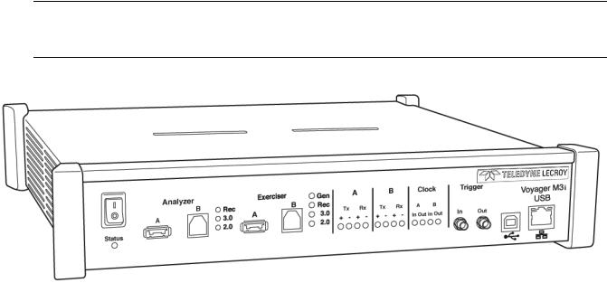
Teledyne LeCroy Corporation |
Voyager M3/M3i Analyzer |
|
|
1.2Voyager M3/M3i Analyzer
The Teledyne LeCroy Voyager™ M3/M3i Analyzer and Exerciser system is a multifunction verification system for USB 2.0 and USB 3.0 development and testing. It can record traffic and graphically present logical USB transactions and events. It can also generate USB traffic. The system is connected to a laptop or desktop via its USB or Gigabit Ethernet port (see Figure 1.2 on page 20).
Note:The Voyager M3 and Voyager M3i Analyzer and Exerciser are identical in most respects. The major difference is that Voyager M3i can capture VBus Power information. Otherwise, all mentions of Voyager M3 in this manual also apply to Voyager M3i.
Figure 1.2: Voyager M3/M3i Analyzer Exerciser System
Please see the Readme file on the installation CD for the latest information on host machine requirements and supported operating systems.
1.2.1USB 2.0 and USB 3.0 Features
The system can monitor traffic between USB 2.0 links using standard high speed compliant cables.
If configured for USB 3.0 testing, the system supports monitoring between SuperSpeed links using USB 3.0 cables (see Figure 1.3 on page 21)
20 |
USB Protocol Suite User Manual |
Voyager M3/M3i Analyzer |
Teledyne LeCroy Corporation |
|
|
|
|
Figure 1.3: Direct Connection using USB 3.0 Cables
or through direct connection via MMCX to SMA coaxial cables (see Figure 1.4).
Figure 1.4: Direct Connection using SMA Differential Tap
1.2.2General Description
The Analyzer connects to a portable or desktop host machine through the USB port. The host machine configures and controls the Analyzer. The “CATC Trace™” user interface is an industry standard for documenting the performance of high speed serial protocols.
The USB protocol Analyzer provides traffic capture and analysis. Hardware triggering allows capture of real time events. Hardware filtering allows filtering different packet types in or out of the recording. Filtering also allows you to preserve recording memory, for extended recording time.
USB Protocol Suite User Manual |
21 |
Teledyne LeCroy Corporation |
Voyager M3/M3i Analyzer |
|
|
The trace viewer application displays recorded data in colored graphics. The application has advanced search and viewing capabilities that allow you to quickly locate specific data, errors, and other conditions.
The system functions with any personal host machine having the Microsoft®
Windows® XP, Windows 8, or Windows 7 (32 or 64) operating system and a functional USB interface or Ethernet port.
The system provides on the fly detection of, and triggering on, such events as Tokens and Errors. Whether recording manually or with a specified trigger condition, the system continuously records the link data, in a wrap around fashion, until manually stopped or until the system detects the Trigger Event and records the specified post trigger amount of link data.
Upon detection of a triggering event, the Analyzer continues to record data up to a point specified by you. You can individually enable or disable real time event detection to allow triggering on events as they happen, including predefined exception or error conditions and user defined sets of trigger events. An externally supplied signal can trigger the Analyzer.
You can use search functions to investigate particular events. In addition to immediate analysis, you can print any part of the data. You can save the data on disk for later viewing. You can generate timing information and data analysis reports.
Please refer to the Universal Serial Bus Specification for details on the protocol. The USB specification is available from the USB Implementers Forum (USB IF) at:
USB Implementers Forum |
Tel: +1/503.296.9892 |
1730 SW Skyline Blvd. |
Fax: +1/503.297.1090 |
Suite 203 |
Web: http://www.usb.org/ |
Portland, OR 97221 |
|
|
|
1.2.3Features
General
Fully complies with USB specification revisions.
Supports the Link Power Management extension.
Uses field upgradeable firmware and recording engine.
Supports all USB speeds (5 Gb/s, 480 Mb/s, 12 Mb/s, and 1.5 Mb/s).
Displays bus traffic using color and graphics in the user friendly CATC Trace inter face.
Has free non recording, view only Trace Viewer software.
Comes with online manual.
Self diagnoses at power on.
Uses software upgradable Exerciser function.
Allows remote control of USB analyzers in a network.
22 |
USB Protocol Suite User Manual |
Voyager M3/M3i Analyzer |
Teledyne LeCroy Corporation |
|
|
|
|
Flexible 3.0 Calibration
Each link can be calibrated with respect to received equalization and gain.
Physical Components
Desktop or portable Microsoft Windows XP, Windows 8, or Windows 7 (32 or 64) host machine with USB or Ethernet capability
Plug and Play USB installation
1 GB or 4 GB of physical data recording memory
USB 2.0 Hi Speed connection to desktop or portable host machine
Internal wide range AC power supply
Expansion port for future enhancements
SMA connectors and USB 3.0 connectors for SuperSpeed capture and generation
External clock inputs and outputs
Recording Options
Versatile triggering: bit wise value and mask data patterns up to sixteen bytes wide for Setup transactions and data packets
Triggering on new High Speed PIDs and split transaction special tokens (ERR, SPLIT, PING, NYET, DATA2, and MDATA) (2.0)
CATC Trace display and enumeration of High Speed Micro Frames (2.0)
Three forms of triggering: Snapshot, Manual, and Event
Transaction sequencer: Allows triggering on a token qualified by a data pattern and/or specific handshake, or can filter transactions (for example, NAK’d transac tions) (2.0)
Advanced triggering with event counting and sequencing
Dedicated trigger for recording input and output used to interface to external test equipment
Triggering on multiple error conditions: PID bad, bit stuffing bad, CRC bad, end of packet bad, babble, activity loss, frame length violation, time out or turn around violation, data toggle violation, Token, Bus Conditions, Data Length, and excessive empty frames (2.0)
Real time traffic capture filtering and data packet truncation variable up to 256 bytes (2.0)
Adjustable buffer size from 0.4 MB to 1 GB or 4 GB
Idle filtering (3.0)
Display Options
Utilizes the CATC Trace graphical display of bus packets, transactions, split transactions, and transfers.
Groups numerous packets and transactions under a single transfer while quickly decoding all essential information.
Decodes split transactions upstream and downstream of a transaction translator with a special hierarchical view.
Has reports summarizing key statistics and conditions of interest, with the ability to jump to the selected item in the trace display.
Uses a Trace Viewer that is backward compatible with USB Advisor™,
USB Chief™, USB Inspector™, and USB Detective™ trace files, which are con verted upon loading.
USB Protocol Suite User Manual |
23 |
Teledyne LeCroy Corporation |
Voyager M3/M3i Analyzer |
|
|
Indicates trigger position by different pre trigger and post trigger packet colors.
Sets markers to assist with navigation and time calculations. Each marker can contain unique comments.
Hides start of frame (SOF) packets, as well as any packet or transaction from a device address and endpoint.
Searches for a specific PID.
Detects and alerts you to every potential bus error and protocol violation, and their combinations.
Has high resolution, accurate time stamping of bus packets and timing measure ment and analysis functions.
Allows search and packet hiding.
Allows device class decoding and user defined protocol decoding.
Has a Data View (2.0 and 3.0).
Uses Link Tracker to view symbols of traffic (3.0).
Uses a Spec View to show packets in the same format as the USB 3.0 specifica tion (3.0).
Has Quick Timing Markers to immediately show time deltas and bandwidth use.
1.2.4Hi-Speed Slow Clock
Trace and generate High Speed traffic at fractional (slow) clock rate capability (2.0)
1.2.5Traffic Generation
USB 2.0 and 3.0 traffic generation options allow you to transmit custom packets over standard USB cables with low level control of headers, payloads, timing, and link states. The Exerciser can play back trace files bit for bit, allowing validation engineers to recreate problems reported in the field or test specific functionality.
To build generation script files, you can edit example test scenarios or export any traffic stream from a previously recorded trace. The Voyager Exerciser includes a
Generation Script Editor.
A script pre processor allows you to organize script code and create reusable generation blocks.
For USB 3.0 applications, test scenarios can contain multi stage traffic generation blocks that include Boolean expressions, LOOP, DO CASE, and IF THEN logical branching.
The Voyager USB 2.0 Exerciser can transmit low, full, or high speed traffic and supports both host and device emulation. It is backward compatible with existing USBTrainer traffic generation scripts.
For USB 2.0 applications, the Exerciser supports both bitstream mode or Intelliframe mode. In Intelliframe mode, the Exerciser can wait for the appropriate response from the DUT before transmitting the next packet. For example, after issuing an IN, the generator waits for the DATAx packet returned by the device to finish, and then issues an ACK. When NAKs are received, the Exerciser can automatically resend the previous packet.
24 |
USB Protocol Suite User Manual |
Voyager M3/M3i Analyzer |
Teledyne LeCroy Corporation |
|
|
|
|
ReadyLink™ Emulation
The Teledyne LeCroy Voyager USB 3.0 Exerciser features ReadyLink Emulation Mode. The ReadyLink feature handles all USB 3.0 link training and link flow control, allowing the emulator to operate at full line rate and respond to the DUT as defined by the specification. The ReadyLink Emulation Mode helps simplify development of USB 3.0 test scenarios.
By default, ReadyLink Emulation Mode automatically manages:
Header Packet Acknowledgements (L_GOOD_n)
Buffer Credit (L_CRD_x)
SKIPs at required intervals (SKP)
Link Synchronization
Responds to LFPS (Polling.LFPS)
Responds to polling sequence (Polling.RxEQ)
Responds to TS1 / TS2 handshaking sequence
Responds to SS.Inactive (with RX.Detect)
Power Management Link Commands
Responds to LGO_Un (with LAU)
Responds to LAU (with LMPA)
Test scripts can customize ReadyLink Emulation Mode to include error scenarios, such as:
Header LBADs
Invalid link commands
8B10B / CRC Error
Running Disparity Error
Corrupt Link Commands
Corrupt Flow Control (Wrong L_CRD_x, Wrong L_GOOD_n, Drop L_Good_n)
Corrupt Header Packet acknowledgement (Send LBAD, LRTY)
Corrupt Packet Framing (SHP, SDP, END)
At the packet level, you can send customized data payloads anywhere within the stream to insert logic errors, perform corner case, or do stress testing. Commands, such as the Set ErrWrongLCRD command, allow link layer error injection anywhere within the script.
1.2.6Notes on LFPS Signals
Voyager Exerciser requires received “Ping” LFPS signals to be a minimum of 150 nanoseconds to be reliably recognized.
Voyager Analyzer can recognize “Ping” LFPS signals above 60 nanoseconds and report their durations to ±15 nanoseconds of accuracy.
USB Protocol Suite User Manual |
25 |
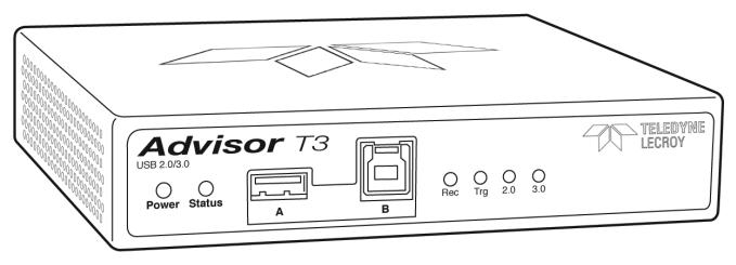
Teledyne LeCroy Corporation |
Advisor T3 |
|
|
1.3Advisor T3
The Teledyne LeCroy USB Advisor T3™ USB 3.0 Protocol Analyzer is a verification system for USB development and testing. It supports both USB 2.0 and USB 3.0. It can record USB traffic and graphically present the logical transactions and events. It connects to a laptop or desktop host machine through its USB port.
Figure 1.5: Advisor T3
The system can monitor traffic between USB 2.0 links using standard high speed compliant cables.
If configured for USB 3.0 testing, the system supports monitoring between SuperSpeed links using USB 3.0 cables.
Please see the Readme file on the installation CD for the latest information on host machine requirements and supported operating systems.
1.3.1General Description
The Analyzer connects to a portable or desktop host machine through its USB port. The host machine configures and controls the Analyzer. The “CATC Trace™” user interface is an industry standard for documenting the performance of high speed serial protocols.
The USB protocol Analyzer provides traffic capture and analysis. Hardware triggering allows capture of real time events. Hardware filtering allows filtering different packet types in or out of the recording. Filtering also allows you to preserve recording memory, for extended recording time.
The trace viewer application displays recorded data in colored graphics. The application has advanced search and viewing capabilities that allow you to quickly locate specific data, errors, and other conditions.
The system functions with any host machine having the Microsoft® Windows® XP, Windows 8, or Windows 7 (32 or 64) operating system and a functional USB interface.
26 |
USB Protocol Suite User Manual |
Advisor T3 |
Teledyne LeCroy Corporation |
|
|
|
|
The system provides on the fly detection of, and triggering on, such events as Tokens and Errors. Whether recording manually or with a specified trigger condition, the system continuously records the link data, in a wrap around fashion, until manually stopped or until the system detects the Trigger Event and records the specified post trigger amount of link data.
Upon detection of a triggering event, the Analyzer continues to record data up to a point specified by you. You can individually enable or disable real time event detection to allow triggering on events as they happen, including predefined exception or error conditions and user defined sets of trigger events. An externally supplied signal can trigger the Analyzer.
You can use search functions to investigate particular events. In addition to immediate analysis, you can print any part of the data. You can save the data on disk for later viewing. You can generate timing information and data analysis reports.
Please refer to the Universal Serial Bus Specification for details on the protocol. The USB specification is available from the USB Implementers Forum (USB IF) at:
USB Implementers Forum |
Tel: +1/503.296.9892 |
1730 SW Skyline Blvd. |
Fax: +1/503.297.1090 |
Suite 203 |
Web: http://www.usb.org/ |
Portland, OR 97221 |
|
1.3.2Features
General
Fully complies with USB specification revisions.
Has field upgradeable firmware.
Supports all USB speeds (5 GB/s, 480 MB/s, 12 MB/s, and 1.5 MB/s).
Displays bus traffic using color and graphics in the CATC Trace interface.
Has free non recording, view only Trace Viewer software.
Comes with online manual.
Self diagnoses at power on.
Allows remote control of USB analyzers in a network.
Flexible 3.0 Calibration
Each link can be calibrated with respect to received equalization and gain.
Physical Components
Desktop or portable Microsoft Windows XP, Windows 8, or Windows 7 (32 or 64) host machine with USB capability
Plug and Play USB installation
2 GB of physical data recording memory
USB 2.0 Hi Speed connection to desktop or portable host machine
DC power supply
Expansion port for optional External Trigger In/Out cable, as well as multi box synchronized recording
USB 3.0 connectors for SuperSpeed capture and generation
USB Protocol Suite User Manual |
27 |
Teledyne LeCroy Corporation |
Advisor T3 |
|
|
Recording Options
Versatile triggering: bit wise value and mask data patterns up to sixteen bytes wide for Setup transactions and data packets
Triggering on new High speed PIDs and split transaction special tokens (ERR, SPLIT, PING, NYET, DATA2, and MDATA) (2.0)
CATC Trace display and enumeration of High Speed Micro Frames (2.0)
Three forms of triggering: Snapshot, Manual, and Event
Transaction sequencer: Allows triggering on a token qualified by a data pattern and/or specific handshake, or can filter transactions (for example, NAK’d trans actions) (2.0)
Advanced triggering with event counting and sequencing
Dedicated trigger for recording input and output used to interface to external test equipment
Triggering on multiple error conditions: PID bad, bit stuffing bad, CRC bad, end of packet bad, babble, activity loss, frame length violation, time out or turn around violation, data toggle violation, Token, Bus Conditions, Data Length, and excessive empty frames (2.0)
Real time traffic capture filtering and data packet truncation variable up to 256 bytes (2.0)
Adjustable buffer size from 0.4 MB to 2 GB
Idle filtering (3.0)
Display Options
Uses the CATC Trace graphical display of bus packets, transactions, split transactions, and transfers.
Groups numerous packets and transactions under a single transfer while quickly decoding all essential information.
Decodes split transactions upstream and downstream of a transaction trans lator with a special hierarchical view.
Has reports summarizing key statistics and conditions of interest, with the ability to jump to the selected item in the trace display.
Has a Trace Viewer backward compatible with USB Advisor™, USB Chief™, USB Inspector™, and USB Detective™ trace files, which are converted upon loading.
Indicates trigger position by different pre trigger and post trigger colors.
Sets markers to assist with navigation and time calculations.
Hides start of frame (SOF) packets and any packet or transaction from a device address and endpoint.
Searches for a specific PID.
Detects, and alerts you to, every potential bus error and protocol violation, and their combinations.
Has high resolution, accurate time stamping of bus packets and timing mea surement and analysis functions.
Has search and packet hiding capabilities.
Allows comprehensive device class decoding and user defined protocol decoding.
Has a Data View (2.0 and 3.0).
Uses Link Tracker to view symbols of traffic (3.0).
28 |
USB Protocol Suite User Manual |
Advisor T3 |
Teledyne LeCroy Corporation |
|
|
|
|
Has a Spec View to show packets in the same format as the USB 3.0 specifica tion (3.0).
Uses Quick Timing Markers to immediately show time deltas and bandwidth use.
USB Protocol Suite User Manual |
29 |
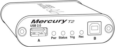
Teledyne LeCroy Corporation |
Mercury T2 |
|
|
1.4Mercury T2
The Teledyne LeCroy Mercury T2™ USB 2.0 Protocol Analyzer is a verification system for USB development and testing. It supports USB 2.0. It is designed to record USB traffic and graphically present the logical transactions and events. It connects to a laptop or desktop host machine via USB 2.0. The Mercury T2 is powered by the USB cable, so no additional power cord is needed.
Figure 1.6: Mercury T2
The system can monitor traffic between USB 2.0 links using standard high speed compliant cables.
The total length of the cables between the Host Under Test and the Device Under Test should be kept to < 4 feet.
Please see the Readme file on the installation CD for the latest information on host machine requirements and supported operating systems.
1.4.1General Description
The Analyzer connects to a portable or desktop host machine through its USB port. The host machine configures and controls the Analyzer. The “CATC Trace™” user interface is an industry standard for documenting the performance of high speed serial protocols.
The USB protocol Analyzer provides traffic capture and analysis. Hardware triggering allows capture of real time events. Hardware filtering allows filtering different packet types in or out of the recording. Filtering also allows you to preserve recording memory, for extended recording time.
The trace viewer application displays recorded data in colored graphics. The application has advanced search and viewing capabilities that allow you to quickly locate specific data, errors, and other conditions.
The system functions with any host machine having the Microsoft® Windows® XP, Windows 8, or Windows 7 (32 or 64) operating system and a functional USB interface.
The system provides on the fly detection of, and triggering on, such events as Tokens and Errors. Whether recording manually or with a specified trigger condition, the system continuously records the link data, in a wrap around fashion, until manually stopped or until the system detects the Trigger Event and records the specified post trigger amount of link data.
30 |
USB Protocol Suite User Manual |
Loading...