


OPERATING INSTRUCTIONS FOR
Model 2120XL
Trace Nitrogen in Argon Analyzer
P/N M84744 11-27-13
DANGER
This instrument is for analyzing nitrogen in argon only.
Do not introduce any flammable or toxic gases into this instrument.
Hazardous voltages exist on certain components internally which may be lethal. Disconnect power before servicing.
Only authorized personnel should conduct maintenance and/or servicing. Before conducting any maintenance or servicing, consult with authorized supervisor/manager.
Teledyne Analytical Instruments

Model 2120XL
Copyright © 2013 Teledyne Analytical Instruments
All Rights Reserved. No part of this manual may be reproduced, transmitted, transcribed, stored in a retrieval system, or translated into any other language or computer language in whole or in part, in any form or by any means, whether it be electronic, mechanical, magnetic, optical, manual, or otherwise, without the prior written consent of Teledyne Analytical Instruments, 16830 Chestnut Street, City of Industry, CA 91748.
Warranty
This equipment is sold subject to the mutual agreement that it is warranted by us free from defects of material and of construction, and that our liability shall be limited to replacing or repairing at our factory (without charge, except for transportation), or at customer plant at our option, any material or construction in which defects become apparent within one year from the date of shipment, except in cases where quotations or acknowledgements provide for a shorter period. Components manufactured by others bear the warranty of their manufacturer. This warranty does not cover defects caused by wear, accident, misuse, neglect or repairs other than those performed by Teledyne or an authorized service center. We assume no liability for direct or indirect damages of any kind and the purchaser by the acceptance of the equipment will assume all liability for any damage which may result from its use or misuse.
We reserve the right to employ any suitable material in the manufacture of our apparatus, and to make any alterations in the dimensions, shape or weight of any parts, in so far as such alterations do not adversely affect our warranty.
Important Notice
This instrument provides measurement readings to its user, and serves as a tool by which valuable data can be gathered. The information provided by the instrument may assist the user in eliminating potential hazards caused by his process; however, it is essential that all personnel involved in the use of the instrument or its interface, with the process being measured, be properly trained in the process itself, as well as all instrumentation related to it.
The safety of personnel is ultimately the responsibility of those who control process conditions. While this instrument may be able to provide early warning of imminent danger, it has no control over process conditions, and it can be misused. In particular, any alarm or control systems installed must be tested and understood, both as to how they operate and as to how they can be defeated. Any safeguards required such as locks, labels, or redundancy, must be provided by the user or specifically requested of Teledyne at the time the order is placed.
Therefore, the purchaser must be aware of the hazardous process conditions. The purchaser is responsible for the training of personnel, for providing hazard warning methods and instrumentation per the appropriate standards, and for ensuring that hazard warning devices and instrumentation are maintained and operated properly.
Teledyne Analytical Instruments, the manufacturer of this instrument, cannot accept responsibility for conditions beyond its knowledge and control. No statement expressed or implied by this document or any information disseminated by the manufacturer or its agents, is to be construed as a warranty of adequate safety control under the user’s process conditions.
Teledyne Analytical Instruments |
ii |

Trace Nitrogen in Argon Analyzer
Specific Model Information
This instrument relies on the known spectrum emitted from a plasma discharge from a distinct gas mixture of variable composition at or near atmospheric pressure. This instrument cannot be used for analysis on any gas or gas mixture other than nitrogen in argon or a mixture specified at the time of purchase. Specific filters carefully chosen and tested at the factory have been installed for the particular gas mixture. Using this instrument to analyze any other gas mixture will result in serious error. Consult the factory for additional information for gas analysis not specified at the time of purchase.
Instrument Serial Number: _______________________
Instrument Range: _______________
Calibrated for: _______________
Background Gas: _______________
|
Zero Gas: |
_______________ |
|
Span Gas: |
_______________ |
Teledyne Analytical Instruments |
iii |
Model 2120XL
Safety Messages
Your safety and the safety of others is very important. We have provided many important safety messages in this manual. Please read these messages carefully.
A safety message alerts you to potential hazards that could hurt you or others. Each safety message is associated with a safety alert symbol. These symbols are found in the manual and inside the instrument. The definition of these symbols is described below:
GENERAL WARNING/CAUTION: Refer to the instructions for details on the specific danger. These cautions warn of specific procedures which if not followed could cause bodily Injury and/or damage the instrument.
CAUTION: HOT SURFACE WARNING: This warning is specific to heated components within the instrument. Failure to heed the warning could result in serious burns to skin and underlying tissue.
WARNING: ELECTRICAL SHOCK HAZARD: Dangerous voltages appear within this instrument. This warning is specific to an electrical hazard existing at or nearby the component or procedure under discussion. Failure to heed this warning could result in injury and/or death from electrocution.
Technician Symbol: All operations marked with this symbol are to be  performed by qualified maintenance personnel only.
NOTE: Additional information and comments regarding a specific component or procedure are highlighted in
No the form of a note.
Symbol
Teledyne Analytical Instruments |
iv |
Trace Nitrogen in Argon Analyzer
CAUTION: THE ANALYZER SHOULD ONLY BE USED ONLY FOR THE PURPOSE AND IN THE MANNER DESCRIBED IN THIS MANUAL.
IF YOU USE THE ANALYZER IN A MANNER OTHER THAN THAT FOR WHICH IT WAS INTENDED, UNPREDICTABLE BEHAVIOR COULD RESULT POSSIBLY ACCOMPANIED WITH HAZARDOUS CONSEQUENCES.
This manual provides information designed to guide you through the installation, calibration operation and maintenance of your new analyzer. Please read this manual and keep it available.
Occasionally, some instruments are customized for a particular application or features and/or options added per customer requests. Please check the front of this manual for any additional information in the form of an Addendum which discusses specific information, procedures, cautions and warnings that may be peculiar to your instrument.
Manuals do get lost. Additional manuals can be obtained from Teledyne at the address given in the Appendix. Some of our manuals are available in electronic form via the internet. Please visit our website at: www.teledyne-ai.com.
Teledyne Analytical Instruments |
v |

Model 2120XL
Table of Contents |
|
|
List of Figures................................................................ |
ix |
|
List of Tables .................................................................. |
x |
|
Introduction..................................................................... |
1 |
|
1.1 |
Overview |
1 |
1.2 |
Typical Applications |
1 |
1.3 |
Features |
2 |
1.4 |
Front Panel |
3 |
1.5 |
Rear Panel |
5 |
1.6 |
Internal Components |
6 |
1.7 |
Additional Safety Information |
7 |
1.7.1 Detector Cautions |
8 |
|
1.7.2 Basic Safety Requirements |
9 |
|
1.7.3 Precautionary Labels |
9 |
|
1.7.4 Summary of Known Hazards |
10 |
|
|
1.7.4.1 Electrocution |
10 |
|
1.7.4.2 Pressure |
10 |
|
1.7.4.3 Purging |
11 |
|
1.7.4.4 Safe Repair Procedures |
11 |
|
1.7.4.5 General Precautions for Handling and Storing |
|
|
High Pressure Gas Cylinders |
11 |
Operational Theory....................................................... |
13 |
|
2.1 |
The Analyzer |
13 |
2.2 |
Sample System |
14 |
Installation..................................................................... |
17 |
|
3.1 |
Unpacking the Instrument |
17 |
|
Teledyne Analytical Instruments |
vi |
Trace Nitrogen in Argon Analyzer
3.2 |
Choosing a Location |
18 |
3.3 |
Mounting |
18 |
3.4 |
Rear Panel Connections |
19 |
3.5 |
Electrical Connections |
20 |
3.5.1 Primary Input Power |
20 |
|
3.5.2 50-Pin Equipment Interface Connector |
20 |
|
3.5.3 RS-232 Port |
26 |
|
3.6 |
Gas Connections |
27 |
3.6.1 Typical Sample System |
29 |
|
3.6.2 Gas Connections to the Instrument |
31 |
|
3.7 |
Purging |
31 |
3.8 |
Calibration |
33 |
3.9 |
Installation Checklist |
33 |
Operation.......................................................................35
4.1 |
Powering Up the Analyzer |
36 |
4.2 |
Zero and Span Calibration |
36 |
4.3 |
Setup and Operation General Information |
37 |
4.4 |
Using the Data Entry and Function Buttons |
37 |
4.5 |
Analyzer Functions |
38 |
4.5.1 System Menu |
39 |
|
|
4.5.1.1 Digital Filter |
40 |
|
4.5.1.2 Self-Test |
41 |
|
4.5.1.3 Password Protection |
42 |
|
4.5.1.4 Logout |
46 |
|
4.5.1.5 ERR |
46 |
|
4.5.1.6 Auto Calibration (Auto Cal) |
47 |
|
4.5.1.7 Flow |
49 |
|
4.5.1.8 Tracking During Calibration |
49 |
|
4.5.1.9 Calibration Hold Timer (Calholdtimer) |
50 |
|
4.5.1.10 The Model Screen |
50 |
|
4.5.1.11 Analog Output Calibration (Out_Cal) |
51 |
|
4.5.1.12 Linearize (Lin) |
52 |
Teledyne Analytical Instruments |
vii |
Model 2120XL
4.5.2 The Zero and Span Functions |
54 |
|
|
4.5.2.1 Before Calibration |
54 |
|
4.5.2.2 Recommended Calibration Gases |
55 |
|
4.5.2.3 Zero Cal |
55 |
|
4.5.2.4 Span Calibration |
57 |
4.5.3 The Range Function |
59 |
|
4.5.4 The Alarms Function |
60 |
|
4.6 |
The Analyze Function |
62 |
4.7 |
Signal Output |
62 |
Maintenance.................................................................. |
65 |
|
5.1 |
Routine Maintenance |
65 |
5.2 Routine Maintenance Schedule |
65 |
|
5.3 |
Fuse Replacement |
66 |
5.4 |
System Self Diagnostic Test |
67 |
5.5 |
Error Screens |
68 |
5.6 |
Sensor Replacement |
69 |
Appendix ....................................................................... |
71 |
|
A.1 Specifications |
71 |
|
A.2 Recommended Replacement Parts List |
72 |
|
A.3 Drawing List |
73 |
|
Teledyne Analytical Instruments |
viii |
Trace Nitrogen in Argon Analyzer
List of Figures
Figure 1-1 Model 2120XL Front Panel |
3 |
Figure 1-2: Model 2120XL Rear Panel |
6 |
Figure 1-3: Internal Component Identification |
7 |
Figure 3-1: Required Front Door Clearance |
19 |
Figure 3-2: Rear Panel of the Model 2120XL |
19 |
Figure 3-3: Equipment Interface Connector Pin Arrangement |
21 |
Figure 3-4: Remote Valve Connections |
25 |
Figure 3-5: FET Series Resistance |
26 |
Figure 3-6: Suggested Sample System |
29 |
Figure 4-1: Hierarchy of Functions and Sub Functions |
39 |
Figure 5-1: Removing Fuse Block from Housing |
66 |
Figure 5-2: Installing Fuses |
67 |
Teledyne Analytical Instruments |
ix |

Model 2120XL
List of Tables
Table 3-1: Analog Output Connections |
21 |
Table 3-2: Alarm Relay Contact Pins |
22 |
Table 3-3: Remote Calibration Connections |
23 |
Table 3-4: Range ID Relay Connections |
24 |
Table 3-5: Commands via RS-232 Input |
26 |
Table 3-6: Required RS-232 Options |
27 |
Table 5-1: Routine Maintenance Schedule |
66 |
Teledyne Analytical Instruments |
x |
Trace Nitrogen in Argon Analyzer
DANGER
COMBUSTIBLE GAS USAGE
WARNING
This is a general purpose instrument designed for use in a non-hazardous area. It is the customer's responsibility to ensure safety especially when combustible gases are present since the potential of gas leaks always exist.
Never introduce gases other than argon into the analyzer. If explosive, flammable or corrosive gases or gas mixtures are allowed to flow into the analyzer, fire or explosion can result.
Sample gas introduced must be at or very close to atmospheric pressure or damage to the detector will result.
To avoid serious injury, read all precautionary labels attached to equipment, cylinders, containers, and boxes prior to start-up.
Labels attached in appropriate areas of the analyzer warn you of inherent hazards associated with the system. For personal safety, read the labels and perform directed precautions before handling the equipment.
The customer should ensure that the principles of operating this equipment are well understood by the user. Misuse of this product in any manner, tampering with its components, or unauthorized substitution of any component may adversely affect the safety of this instrument.
Since the use of this instrument is beyond the control of Teledyne Analytical Instruments, referred as TAI, no responsibility by TAI, its affiliates, and agents for damage or injury from misuse or neglect of this equipment is implied or assumed.
Teledyne Analytical Instruments |
xi |

Model 2120XL
Teledyne Analytical Instruments |
xii |

Trace Nitrogen in Argon Analyzer |
Introduction |
|
|
|
|
|
|
|
Introduction
1.1 Overview
This manual describes installation, operation and maintenance for the Model 2120XL Trace Nitrogen in Argon Gas Analyzer. Section 1 describes the analyzer in general terms and provides additional safety information pertinent to the proper operation of the instrument.
The Teledyne Model 2120XL Trace Nitrogen in Argon Gas Analyzer is a robust analytical tool for measuring trace amounts of nitrogen in argon. Using precise optical filtering, single line emission characteristic of nitrogen is produced with an intensity proportional to the nitrogen concentration.
The Model 2120XL has three user programmable analysis ranges extending from 0-1 ppm to 0-100 ppm with corresponding analog output signals that are proportional to the concentration on the selected range. The nitrogen concentration is displayed on the front panel and the analog output signals are available at the rear panel. Digital communication is achieved with a standard RS-232 serial port.
The system is easy to operate with all controls and indicators accessible from the front panel. Digital flow control, two adjustable concentration alarms, system alarm, self-diagnostics are just a few of the many features included on the standard Model 2120XL instrument.
1.2 Typical Applications
The Model 2120XL Trace Nitrogen in Argon Gas Analyzer is used in a wide range of applications including:
Air separation plants
Argon Purification Plants
Specialty Gas Laboratories
Specialty Steel Manufacturing
Gas Management/Monitoring Systems
|
|
|
Teledyne Analytical Instruments |
1 |
|

Introduction |
Model 2120XL |
|
|
|
|
|
|
|
Quality Control for Truck Fills & Gas Cylinders
Process Control
New Line Certification
Chemical Plants
Welding Gas Management
Semiconductor Manufacturing
1.3Features
The Model 2120XL comes equipped with the following standard features:
A 2-line alphanumeric vacuum fluorescent display (VFD) screen, driven by microprocessor electronics that continuously prompts and informs the operator.
High resolution, accurate readings of nitrogen content from low ppm levels through 100 ppm in argon. Large, bright, meter readout.
Advanced high frequency plasma generator produces stable electroluminescent discharge with minimal heating yielding a spectral emission characteristic of the gas mixture.
Custom low-noise optical filter for precise narrow band selection and low optical interference.
Amplified optics circuit for stable nitrogen detection at low ppb level.
Microprocessor based electronics: 8-bit CMOS microprocessor with 32 kB RAM and 128 kB ROM.
Three user definable output ranges (from 0-1 ppm through 0- 100 ppm) allow best match to users process and equipment.
Auto Ranging allows analyzer to automatically select the proper preset range for a given measurement. Manual override allows the user to lock onto a specific range of interest.
Two adjustable concentration alarms and a system failure alarm.
Teledyne Analytical Instruments |
2 |
Trace Nitrogen in Argon Analyzer |
Introduction |
|
|
|
|
|
|
|
Extensive self-diagnostic testing, at startup and on demand, with continuous power-supply monitoring.
Two way RFI protection.
RS-232 serial digital port for use with a computer or other digital communication device.
Four analog outputs: two for measurement (0–1 VDC and isolated 4–20 mA DC) and two for range identification.
Convenient and versatile, steel, flush-panel or rackmountable case with slide-out electronics drawer.
1.4Front Panel
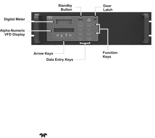
Operator controls and displays are located on the front panel as shown in Figure 1-1.
Figure 1-1 Model 2120XL Front Panel
The standard 2120XL Nitrogen in Argon Analyzer is panel mounted designed for easy installation in a standard 19” instrument rack. All user controls and displays accessible from the front panel.
The front panel has thirteen buttons for operating the analyzer, a digital meter, and an alphanumeric vacuum fluorescent (VFD) display.
|
|
|
Teledyne Analytical Instruments |
3 |
|

Introduction |
Model 2120XL |
|
|
|
|
|
|
|
Function Keys:
Six touch-sensitive membrane switches are used to change the specific function performed by the analyzer:
Analyze |
Perform analysis for nitrogen content in an argon |
|
gas mixture. |
System |
Perform system-related tasks (described in detail |
|
in Chapter 4, Operation.). |
Span |
Span calibrate the analyzer. |
Zero |
Zero calibrate the analyzer. |
Alarms |
Set the alarm setpoints and attributes. |
Range |
Set up the 3 user definable ranges for the |
|
instrument. |
Data Entry Keys:
Six touch-sensitive membrane switches are used to input data to the instrument via the alphanumeric VFD display:
◄► |
Select between functions currently displayed on |
|
the VFD screen. |
▲▼ |
Increment or decrement values of functions |
|
currently displayed. |
Enter |
Advances VFD display to the next screen in a |
|
series or returns to the Analyze screen if none |
|
remain. |
Escape |
Backs VFD display to the previous screen in a |
|
series or returns to the Analyze screen if none |
|
remain also used to abort an entry. |
Digital Meter Display:
The meter display is a Light Emitting Diode (LED) device that produces large, bright, 7-segment numbers that are legible in any lighting. It produces a continuous readout from 0-10,000 ppm. It is accurate across all analysis ranges without the discontinuity inherent in analog range switching.
Alphanumeric Interface Screen:
The VFD screen is an easy-to-use interface from operator to analyzer. It displays values, options, and messages that give the operator immediate feedback.
Teledyne Analytical Instruments |
4 |
Trace Nitrogen in Argon Analyzer |
Introduction |
|
|
|
|
|
|
|
Standby Button:
The Standby turns off the display and outputs, but circuitry is still operating.
CAUTION: THE POWER CABLE MUST BE UNPLUGGED TO FULLY DISCONNECT POWER FROM THE INSTRUMENT. WHEN CHASSIS IS EXPOSED OR WHEN ACCESS DOOR IS OPEN AND POWER CABLE IS CONNECTED, USE EXTRA CARE TO AVOID CONTACT WITH LIVE ELECTRICAL CIRCUITS
.
Access Door:
For access to internal components of the analyzer, the front panel swings open when the latch in the upper right corner of the panel is pressed all the way in with a narrow gauge tool. Accessing the main circuit board requires unfastening rear panel screws and sliding the unit out of the case.
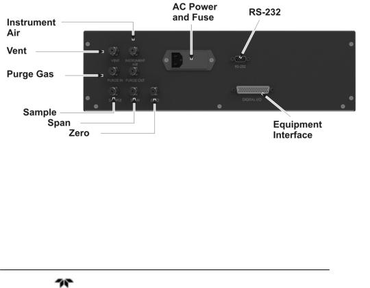
1.5 Rear Panel
The rear panel, shown in Figure 1-2, contains the gas and electrical connectors for external inlets and outlets. Some of those depicted are optional and may not appear on your instrument. The connectors are described briefly here and in detail in Chapter 3 Installation.
Power Connection Universal AC power source.
Digital I/O |
Analog Outputs: |
|
|
|
0–1 VDC nitrogen concentration |
|
|
|
plus 0-1 VDC range ID, and |
|
|
|
isolated 4–20 mA DC nitrogen |
|
|
|
concentration plus 4-20 mA DC |
|
|
|
range ID. |
|
|
|
Alarm Signals: |
|
|
|
2 concentration alarms and 1 |
|
|
|
system alarm. |
|
|
|
Remote Span/Zero |
|
|
|
Digital inputs allow external |
|
|
|
control of analyzer calibration. |
|
|
|
|
|
|
Teledyne Analytical Instruments |
5 |
||
Introduction |
Model 2120XL |
|
|
|
|
|
|
|
|
Calibration Contact |
|
Notifies external equipment that |
|
instrument is being calibrated and |
|
readings are not monitoring |
|
sample. |
|
Range ID Contacts |
|
Four separate, dedicated, range |
|
relay contacts. Low, Medium, |
|
High, Cal (not used). |
RS-232 Port |
Serial digital concentration signal |
|
output and control input. |
Gas Inlet and Outlet |
One inlet and one vent. |
Purge Connections |
Inlet and outlet connections for |
|
purging the analyzer. |
Instrument Air |
Used for driving optional auto |
|
calibration valves. |
Figure 1-2: Model 2120XL Rear Panel
1.6 Internal Components
The internal components can be accessed by removing the top cover of the analyzer. Figure 1-3 shows an inside view of the analyzer
Teledyne Analytical Instruments |
6 |

Trace Nitrogen in Argon Analyzer |
Introduction |
|
|
|
|
|
|
|
and identifies specific components of the analyzer. See also Figure 1-4 for internal components inside the card cage.
Figure 1-3: Internal Component Identification
WARNING: HIGH VOLTAGE. ELECTROCUTION HAZARD. UNPLUG THE ANALYZER BEFORE REMOVING THE COVER. THE OUTPUT OF THE HIGH-VOLTAGE TRANSFORMER AND THE ANALYTICAL CELL ELECTRODES CAN APPROACH VOLTAGES OF 10,000 VAC. THE ANALYZER SHOULD BE SERVICED ONLY BY A QUALIFIED SERVICE TECHNICIAN.
1.7 Additional Safety Information
Note: The material provided in this section contains information to promote safety in the operation and maintenance of this equipment. It is not intended to supersede, replicate, or replace any safety documentation or procedures provided
from or established by official safety sources.
Teledyne Analytical Instruments |
7 |
Introduction |
Model 2120XL |
|
|
|
|
|
|
|
Do NOT operate the Model 2120XL Trace Nitrogen in Argon Gas Analyzer until you read and understand the operating, maintenance, and safety instructions included in this manual.
Anyone involved with the operation of this equipment including plant engineering, operations, and management, must understand the potential hazards involved, and know and observe all required safety precautions.
Your safety and the safety of equipment, nearby facilities, and personnel require a proper safety attitude and emphasis on safe work procedures. This is the essence of any good safety program. If at any time you identify safety deficiencies, immediately correct them and bring them to the attention of management.
Before an accident can be prevented, it must be anticipated. Use pre-job discussions with your coworkers and supervisors to identify hazards and the means to avoid them. At your facility, various gases may exist in liquid and/or gaseous states. Familiarize yourself with the hazards associated with each gas found at your facility.
Read and understand the Material Safety Data Sheets (MSDS) for the materials used with this equipment. All personnel who work in the vicinity of this equipment should read, understand, and follow all safety information contained in the MSDSs, in addition to following all government and facility safety regulations.
CAUTION: NEVER INTRODUCE GASES OTHER THAN ARGON INTO THE ANALYZER. IF EXPLOSIVE, FLAMMABLE, OR CORROSIVE GASES OR GAS MIXTURES ARE ALLOWED TO FLOW INTO THE ANALYZER, FIRE OR EXPLOSION CAN RESULT. THIS ANALYZER IS NOT DESIGNED TO BE USED IN HAZARDOUS AREAS.
1.7.1 Detector Cautions
The Model 2120XL uses a detection technique based on spectroscopic emission. The detector is a thin-walled pure quartz cell located in an electromagnetic field created by a specific high intensity plasma generator. This electromagnetic field creates a plasma that emits light at different wavelengths. A filter for the nitrogen is used to avoid any interference and get the best performance.
Teledyne Analytical Instruments |
8 |
Trace Nitrogen in Argon Analyzer |
Introduction |
|
|
|
|
|
|
|
Since the cell is made of thin quartz, this analyzer must be used at atmospheric pressure to avoid cell damage. Any back pressure in the detector will cause damage and require replacement of the module. Make sure the vent is at atmospheric pressure and without restrictions or blockage.
1.7.2 Basic Safety Requirements
The following safety guidelines apply at all times when working with the Model 2120XL analyzer:
Prevent electrical shock — Unplug and remove the AC power cord from the rear panel before opening and working on the analyzer. Use tools designed for work on electrical equipment.
Prevent injury — Always wear safety glasses and appropriate safety protection. Ensure that all tools and instruments used during installation and maintenance are in good condition. Be aware that high-velocity gas may be released at vents and safety relief valves.
Follow posted precautions — Read all precautionary labels attached to the equipment. Be sure to read all cylinder labels and warnings. Comply with all precautions before handling the equipment.
Situations may develop for which no written procedures exist. Think carefully before acting. Know the function of each valve and switch, and its effect on the equipment. Carefully review all operating procedures before starting up this equipment to ensure knowledge and understanding.
1.7.3 Precautionary Labels
WARNING: TO AVOID SERIOUS INJURY, READ ALL CAUTION LABELS ATTACHED TO EQUIPMENT, CYLINDERS, CONTAINERS, AND BOXES PRIOR TO START-UP.
Labels attached in appropriate areas of the analyzer warn you of inherent hazards associated with the system. For personal safety, read the labels and perform directed instructions before handling the equipment.
Teledyne Analytical Instruments |
9 |

Introduction |
Model 2120XL |
|
|
|
|
|
|
|
1.7.4 Summary of Known Hazards
This equipment is designed to minimize your exposure to the process gases and other known hazards. Read and thoroughly understand all safety aspects of this system and its operation before operating or maintaining the equipment.
1.7.4.1 ELECTROCUTION
WARNING: DO NOT OPERATE THE ANALYZER WITHOUT THE COVER SECURED IN PLACE. THE OUTPUT OF THE HIGH-VOLTAGE TRANSFORMER AND THE ANALYTICAL CELL ELECTRODES CAN APPROACH VOLTAGES OF 6,000 VAC OR HIGHER. TO GUARD AGAINST ELECTRICAL SHOCK AND POSSIBLE ELECTROCUTION, THE ANALYZER SHOULD BE SERVICED ONLY BY A QUALIFIED SERVICE TECHNICIAN.
Adherence to the following guidelines helps guard against electrical shock:
For safety and proper performance, this analyzer must be connected to a properly grounded three-wire source of electrical power.
Tampering or unauthorized substitution of components may adversely affect the safety of this instrument. Use only factory-approved components for repair.
Before checking or replacing any chassis component, turn off the power and remove the AC power cord from the rear panel.
1.7.4.2PRESSURE
WARNING: MISHANDLING OF GAS CYLINDERS COULD RESULT IN DEATH, SERIOUS INJURY, OR PROPERTY DAMAGE. HANDLE AND STORE GAS CYLINDERS WITH EXTREME CARE AND IN ACCORDANCE WITH MANUFACTURER'S INSTRUCTIONS.
Sudden or uncontrolled release of pressurized gas can cause serious injury. The hazards of high pressure can be avoided through careful inspection and handling of cylinders and equipment with proper
Teledyne Analytical Instruments |
10 |

Trace Nitrogen in Argon Analyzer |
Introduction |
|
|
|
|
|
|
|
regulation. Read and understand the MSDSs for the process gases used before operating this analyzer. More detailed information on the precautions and safe practices to follow when handling cylinders can be found in the CGA pamphlet P-1, Safe Handling of Compressed Gases in Cylinders.
1.7.4.3 PURGING
CAUTION: EQUIPMENT DAMAGE MAY RESULT IF THE ANALYTICAL CELL IN THIS UNIT IS EXPOSED TO PRESSURE ABOVE ATMOSPHERIC PRESSURE. THE CELL MAY BREAK OR SHATTER. TO PREVENT THIS, ALWAYS KEEP THE VENT AT ATMOSPHERIC PRESSURE.
DO NOT EXCEED 20 PSIG (138 KPA) AT THE
SAMPLE INLET.
DO NOT BLOCK THE VENT.
Follow applicable safety precautions to ensure that an oxygendeficient atmosphere is not created in the work area. Use low parts per million (ppm) nitrogen in argon gas with proper regulation to avoid contaminating the sampling system.
1.7.4.4 SAFE REPAIR PROCEDURES
Any repair work must be performed by a qualified service technician. Use only factory-approved components for repair.
Analyzer manifold purging as well as subsequent repair work must be performed by experienced personnel.
Ventilate working area to prevent any leaking supply gas from accumulating. Vent all gases to the outside.
Vent all pressure relief valves out of enclosed areas. Piping must be properly sized to allow safety devices to operate according to specifications.
De-pressurize supply gas piping before working on it.
1.7.4.5 GENERAL PRECAUTIONS FOR HANDLING AND STORING HIGH PRESSURE GAS CYLINDERS
Compressed gases have properties that can cause serious accidents, injuries, and even death if proper precautions and safety practices are
Teledyne Analytical Instruments |
11 |

Introduction |
Model 2120XL |
|
|
|
|
|
|
|
not followed. Therefore, during handling and use of these gases, be certain to use applicable safety precautions described by your local compressed gas supplier, the Compressed Gas Association, and/or OSHA regulations.
1.Read the label on all cylinders BEFORE using to identify the cylinder contents. If the label is illegible, return the cylinder to the supplier. DO NOT ASSUME THE CONTENTS.
2.Secure cylinders in storage and in use to an immovable structure to prevent accidental falling or movement. Read the relevant safety codes.
3.Store or move cylinders ONLY in the vertical position. DO NOT move or transport cylinders with regulators attached.
4.Store cylinders in a well ventilated area away from heat or ignition sources.
5.When installing tubing, provide ONLY approved, adequate pressure reducing regulators and pressure relief devices to prevent over-pressurizing of tubing and equipment.
6.Never drop cylinders or permit them to strike each other violently.
7.Cylinders may be stored in the open but, in such cases, should be protected against extremes of weather and from damp ground (to prevent rusting) in areas where extreme temperatures are prevalent, store cylinders in the shade.
8.The valve protection cap should be left on each cylinder until cylinder has been secured against a wall or bench, or placed in a cylinder stand and is ready for use.
9.Avoid dragging, rolling or sliding cylinders even for a short distance. Move cylinders by using a suitable hand truck.
10.Never tamper with safety devices in valves or cylinders.
11.Do not store full and empty cylinders together. Serious suck-back can occur when an empty cylinder is attached to a pressurized system.
12.No part of a cylinder should be subjected to a temperature higher than 52°C (125°F). Do not permit flame to come in contact with any part of a compressed gas cylinder.
Teledyne Analytical Instruments |
12 |
Trace Nitrogen in Argon Analyzer |
Operational Theory |
|
|
|
|
|
|
|
Operational Theory
2.1 The Analyzer
The Model 2120XL Trace Nitrogen in Argon Gas Analyzer is a rack mounting self-contained unit for measuring trace amounts of nitrogen in an argon gas stream.
A customer supplied sample system directs a stream of refined argon to the instrument at a pressure between 4 and 20 psig (14-138 kPa). The process stream enters at a constant flow rate and passes through a flow module containing a flow control valve and a mass flow transducer. A gas conditioning unit is installed to remove particulates from the incoming gas sample.
The gas is then fed to a quartz analytical cell where it is ionized in a plasma discharge. The high energy within the plasma results in constant collisions of ions and electrons and yields a characteristic emission spectra intimately associated with the gas comprising the plasma.
The specific line energy is identified for nitrogen and a custom blocking filter is selectively chosen and installed at the factory which is tuned to remove all but the narrow energy associated with the nitrogen emission peak. The light energy passing through the filter is focused on a photon detector also tuned to respond to that wavelength. This instrument can only be used for analyzing nitrogen in argon.
The photodetector produces a signal which is integrated and then amplified. The resulting signal is digitized and processed by a microprocessor and signal processing circuit. The results are displayed on the instrument display as parts per million (ppm). An additional digital to analog circuit transforms the signal back to analog form and produces an output signal, typically 4-20 mA DC that is proportional to the nitrogen concentration on the selected range.
The microprocessor circuit accepts input from the mass flow transducer as well as the user interface. The analyzer software interprets operator key presses and initiates the appropriate action as well as sending signals to the displays for prompting the user for input or data display.
Teledyne Analytical Instruments |
13 |

Operational Theory |
Model 2120XL |
|
|
|
|
|
|
|
After analysis, the gas is returned to the gas flow module. A signal is produced in the flow transducer that is used by the microprocessor to control the flow control valve. From the flow control module, the gas exits the analyzer at atmospheric pressure.
The superior accuracy of the Model 2120XL is achieved through enhanced coupling of the plasma to the process and an advanced plasma generator design. Through proper frequency and intensity control a uniform, precisely located, and highly stable plasma discharge is produced with minimum heat generation. The resulting emission spectra is clear and distinct.
The Model 2120XL is fitted with custom optical filtering and an optics system that is specifically designed to reduce interference. The desired spectral line used for analysis is sharp and focused on the detector.
The detector lifetime is enhanced using a “Duty Cycle Controlled System” by reducing the coating inside the cell. This also results in an increase in sensitivity.
2.2 Sample System
A suitable external sample system must be provided by the customer. The external sample system delivers calibration or sample gas to the analyzer at a suitable pressure.
The sample system may contain a molecular sieve type trap to reduce moisture levels in the sample gas. Moisture produces a wellknown interference line in the spectrum close to that of nitrogen. It is necessary to use moisture-free sample gas or install an efficient moisture trap on the inlet.
Internally the Model 2120XL employs a flow control valve which provides proper flow through the analyzer when the inlet pressure is maintained between 4 to 20 psig. The proper flow rate should be maintained around 100 ccm.
Teledyne Analytical Instruments |
14 |
 Loading...