


 Loading...
Summit T24
PCI Express
Multi-Lane Protocol Analyzer
User Manual
Software Version 7.xx
January 2014

Teledyne LeCroy Protocol Solutions Group
Trademarks and Servicemarks
Teledyne LeCroy, CATC Trace, PCI Express, PETracer, PETracer Summit, Summit T28, Summit T24, Universal Protocol Ana lyzer System, UPAS, and BusEngine are trademarks of Teledyne LeCroy.
Microsoft and Windows are registered trademarks of Microsoft Corporation. Intel and Pentium are registered trademarks of Intel Corporation.
All other trademarks and registered trademarks are property of their respective owners.
THE SPECIFICATIONS AND INFORMATION REGARDING THE PRODUCTS IN THIS MANUAL ARE SUBJECT TO CHANGE WITHOUT NOTICE. ALL INFORMATION, EXAMPLES AND RECOMMENDATIONS IN THIS MANUAL ARE BELIEVED TO BE ACCURATE BUT ARE REPRESENTED WITHOUT WARRANTY OF ANY KIND, EXPRESS OR IMPLIED. USERS ARE FULLY RESPONSIBLE FOR THEIR APPLICATION OF ANY PRODUCTS.
THE SOFTWARE LICENSE AND LIMITED WARRANTY FOR THE ACCOMPANYING PRODUCT ARE SET FORTH IN INFORMATION THAT SHIPPED WITH THE PRODUCT AND ARE INCORPORATED HEREIN BY THIS REFERENCE. IF YOU ARE UNABLE TO LOCATE THE SOFTWARE LICENSE OR LIMITED WARRANTY, CONTACT Teledyne LeCroy FOR A COPY.
© 2013 Teledyne LeCroy, Inc. All rights reserved.
This document may be printed and reproduced without additional permission, but all copies should contain this copyright notice.
WEEE Program
Teledyne LeCroy
3385 Scott Blvd.
Santa Clara, CA 95054
TEL: 800-909-7112 (USA and Canada)
TEL: 408-653-1260 (worldwide)
Summit T24 PCI Express Multi Lane Protocol Analyzer User Manual |
ii |

Contents
Chapter 1: Overview................................................................................................ |
1 |
|
1.1 |
PETracer Analyzer Hardware and Software ......................................................................... |
1 |
|
1.1.1 CATC Trace Software............................................................................................................................. |
2 |
|
1.1.2 Summit T24 Analyzer ............................................................................................................................. |
2 |
|
1.1.3 Other Documents ................................................................................................................................... |
4 |
Chapter 2: Hardware Description .......................................................................... |
5 |
|
2.1 System Components .............................................................................................................. |
5 |
|
2.2 |
Host Machine Requirements ................................................................................................. |
5 |
2.3 |
Summit T24 Front Panel Description.................................................................................... |
6 |
2.4 |
Summit T24 Rear Panel Description ..................................................................................... |
6 |
Chapter 3: Installation and Setup .......................................................................... |
7 |
|
3.1 |
Installing the PETracer Software........................................................................................... |
7 |
3.2 |
Setting Up the Summit T24 Analyzer using a USB Connection ......................................... |
9 |
3.3 |
Networking an Analyzer ......................................................................................................... |
9 |
|
3.3.1 Setup for IP LAN Use ............................................................................................................................. |
9 |
3.4 |
Analyzer Network.................................................................................................................. |
10 |
3.5 |
Interposers and Probes........................................................................................................ |
11 |
3.6 |
Using Interposers ................................................................................................................. |
11 |
|
3.6.1 Gen2 Passive Interposer...................................................................................................................... |
11 |
|
Summit T24 Components................................................................................................................... |
12 |
|
Installing the Gen2 Passive Interposer ............................................................................................. |
12 |
|
Power On Analyzer and then DUT ..................................................................................................... |
12 |
3.7 |
Using Probes......................................................................................................................... |
13 |
|
3.7.1 Example: Connecting the Summit T24 Analyzer to the Device Under Test Using a Gen2 MidBus Probe......... |
13 |
|
Connections Overview for Gen2 MidBus Probe .............................................................................. |
14 |
Summit T24 PCI Express Multi Lane Protocol Analyzer User Manual |
iii |

Teledyne LeCroy |
Contents |
|
|
Connection Procedure........................................................................................................................ |
14 |
|
3.7.2 Example: Connecting the Summit T24 Analyzer to the Device Under Test Using a Gen2 Multi-lead Probe for x1 and x4......15 |
|
|
Components ........................................................................................................................................ |
15 |
|
Connections for Gen2 Multi-lead Probe............................................................................................ |
15 |
|
Connection Procedure........................................................................................................................ |
16 |
|
3.7.3 Example: Connecting the Summit T24 Analyzer to the Device Under Test Using a Gen2 Multi-lead Probe for x4 |
.......16 |
|
Components ........................................................................................................................................ |
16 |
|
Connections Overview for Gen2 Multi-lead Probe........................................................................... |
16 |
|
Connection Procedure........................................................................................................................ |
16 |
|
MicroD to CATC Sync Cable .............................................................................................................. |
17 |
Chapter 4: Software Overview ............................................................................. |
19 |
|
4.1 |
The PETracer Software ........................................................................................................ |
19 |
4.2 |
Application Layout ............................................................................................................... |
20 |
4.3 |
Using the Toolbar ................................................................................................................. |
21 |
4.4 |
Multi-Segment Toolbar......................................................................................................... |
24 |
|
4.4.1 Toolbar Hide Buttons ........................................................................................................................... |
24 |
4.5 |
Using the Menus................................................................................................................... |
26 |
|
4.5.1 File Menu .............................................................................................................................................. |
26 |
|
4.5.2 Setup Menu ........................................................................................................................................... |
27 |
|
4.5.3 Record Menu......................................................................................................................................... |
27 |
|
4.5.4 Report Menu.......................................................................................................................................... |
28 |
|
4.5.5 Search Menu ......................................................................................................................................... |
29 |
|
4.5.6 View Menu ............................................................................................................................................. |
30 |
|
4.5.7 Tools Menu............................................................................................................................................ |
31 |
|
4.5.8 Window Menu ....................................................................................................................................... |
31 |
|
4.5.9 Help Menu ............................................................................................................................................. |
32 |
4.6 |
Dashboard View.................................................................................................................... |
32 |
|
Launching and Setting Recording Option from Dashboard View .................................................. |
34 |
4.7 |
Tool Tips................................................................................................................................ |
34 |
4.8 |
Keyboard Shortcuts ............................................................................................................. |
34 |
4.9 |
Status Bar.............................................................................................................................. |
35 |
|
4.9.1 Recording Progress Bar ...................................................................................................................... |
35 |
|
4.9.2 Recording Status.................................................................................................................................. |
36 |
|
4.9.3 Recording Activity................................................................................................................................ |
36 |
|
4.9.4 Search Direction Indicator................................................................................................................... |
37 |
4.10 Making a PCI Express Recording...................................................................................... |
37 |
|
|
4.10.1 Stopping a Recording ........................................................................................................................ |
38 |
|
4.10.2 Saving a Recording ............................................................................................................................ |
39 |
iv |
Summit T24 PCI Express Multi Lane Protocol Analyzer User Manual |
Contents |
Teledyne LeCroy |
|
|
|
|
4.11 Recording Multi-Segmented CATC Traces ...................................................................... |
39 |
|
|
4.11.1 How to Create a Multisegment Recording ....................................................................................... |
39 |
|
4.11.2 What Gets Created ............................................................................................................................. |
39 |
4.12 PETracer Files..................................................................................................................... |
40 |
|
|
4.12.1 CATC Trace Files................................................................................................................................ |
40 |
|
4.12.2 Recording Options Files .................................................................................................................... |
40 |
|
4.12.3 Display Options Files ......................................................................................................................... |
41 |
4.13 Saving CATC Trace Files ................................................................................................... |
41 |
|
|
4.13.1 Using the Save As Function .............................................................................................................. |
41 |
|
4.13.2 Saving a Portion of a CATC Trace .................................................................................................... |
42 |
4.14 Exporting a CATC Trace File ............................................................................................. |
43 |
|
4.15 Printing Data Files .............................................................................................................. |
43 |
|
4.16 Analyzer Chat Window....................................................................................................... |
44 |
|
|
4.16.1 CrossSync Control Panel .................................................................................................................. |
45 |
|
Launching the CrossSync Control Panel ......................................................................................... |
46 |
Chapter 5: Recording Options ............................................................................. |
47 |
|
5.1 |
Recording Overview............................................................................................................. |
47 |
5.2 |
General Tab........................................................................................................................... |
47 |
5.3 |
Recording Options-General Tab ......................................................................................... |
48 |
5.4 Simple and Advanced Mode................................................................................................ |
49 |
|
5.5 |
Trace Filename and Path ..................................................................................................... |
49 |
5.6 |
Saving and Loading Previously Saved Recording Options ............................................. |
50 |
|
5.6.1 Setting Default Recording Options..................................................................................................... |
50 |
|
5.6.2 Loading Recording Options ................................................................................................................ |
50 |
|
5.6.3 Saving Recording Options .................................................................................................................. |
51 |
5.7 |
Recording Type..................................................................................................................... |
51 |
|
5.7.1 Snapshot ............................................................................................................................................... |
52 |
|
5.7.2 Manual Trigger...................................................................................................................................... |
52 |
|
5.7.3 Event Trigger ........................................................................................................................................ |
52 |
5.8 |
Buffer Size............................................................................................................................. |
52 |
5.9 |
Upload Size ........................................................................................................................... |
53 |
5.10 Misc...................................................................................................................................... |
53 |
|
5.11 Recording Mode.................................................................................................................. |
54 |
|
|
5.11.1 BitTracer Recording ........................................................................................................................... |
54 |
5.12 Trigger Position .................................................................................................................. |
54 |
|
5.13 Save As MultiSegment Trace............................................................................................. |
54 |
|
|
5.13.1 Viewing Multisegmented Files .......................................................................................................... |
55 |
Summit T24 PCI Express Multi Lane Protocol Analyzer User Manual |
v |
|

Teledyne LeCroy |
Contents |
5.14 Link Settings ....................................................................................................................... |
56 |
5.14.1 Speed................................................................................................................................................... |
56 |
5.14.2 Link Width ........................................................................................................................................... |
57 |
5.14.3 Upstream and Downstream ............................................................................................................... |
57 |
5.14.4 Reference Clock ................................................................................................................................. |
57 |
5.14.5 Disable Descrambling ........................................................................................................................ |
57 |
5.14.6 Auto-Configure Lane Polarity............................................................................................................ |
57 |
5.14.7 Ignore Idle Errors................................................................................................................................ |
57 |
5.14.8 Swizzling Config... .............................................................................................................................. |
58 |
5.15 Triggering............................................................................................................................ |
59 |
5.15.1 Triggering On (Simple Mode) ............................................................................................................ |
59 |
5.15.2 Triggering On (Advanced Mode)....................................................................................................... |
60 |
5.16 Recording Rules Overview ................................................................................................ |
61 |
5.16.1 Defining Recording Rules.................................................................................................................. |
61 |
5.17 Resources ........................................................................................................................... |
64 |
5.17.1 Packet Match Resource ..................................................................................................................... |
64 |
5.17.2 Basic Resource................................................................................................................................... |
66 |
5.18 Global State and Sequence States.................................................................................... |
67 |
5.18.1 Global State......................................................................................................................................... |
68 |
5.18.2 Sequence State................................................................................................................................... |
69 |
5.19 Navigating Recording Rules.............................................................................................. |
70 |
5.19.1 Toolbar ................................................................................................................................................ |
70 |
5.19.2 Available Events Area ........................................................................................................................ |
71 |
5.19.3 Main Display Area............................................................................................................................... |
71 |
5.19.4 Recording Rules Buttons .................................................................................................................. |
71 |
5.20 Recording Rules Events .................................................................................................... |
71 |
5.21 Properties Dialog Boxes for Events.................................................................................. |
73 |
5.21.1 Accessing the Properties Dialog ...................................................................................................... |
73 |
5.21.2 Event Properties Dialog Box Features ............................................................................................. |
73 |
5.21.3 Link State Dialog ................................................................................................................................ |
74 |
5.21.4 Ordered Set Properties Dialog .......................................................................................................... |
75 |
5.21.5 Error Properties Dialog ...................................................................................................................... |
75 |
5.21.6 DLLP Packet Properties Dialog......................................................................................................... |
76 |
5.21.7 TLP Header Properties Dialog........................................................................................................... |
77 |
5.21.8 TLP Prefix Properties Dialog ............................................................................................................. |
77 |
5.21.9 AHCI Register Properties Dialog....................................................................................................... |
78 |
5.21.10 ATA Command Properties Dialog................................................................................................... |
78 |
5.21.11 NVME Register Properties Dialog ................................................................................................... |
79 |
5.21.12 NVME Command Submission Properties Dialog .......................................................................... |
79 |
5.21.13 NVME Command Completion Properties Dialog ........................................................................... |
80 |
5.21.14 Actions Properties Dialog................................................................................................................ |
80 |
vi |
Summit T24 PCI Express Multi Lane Protocol Analyzer User Manual |
Contents |
Teledyne LeCroy |
|
|
|
|
5.22 Counter................................................................................................................................ |
81 |
5.22.1 How to Set a Counter ......................................................................................................................... |
82 |
5.22.2 How to Increment or Reset a Counter .............................................................................................. |
83 |
5.22.3 Changing the Value of the Counter .................................................................................................. |
84 |
5.22.4 Deleting a Counter.............................................................................................................................. |
84 |
5.23 Timer.................................................................................................................................... |
85 |
5.23.1 How to Set a Timer ............................................................................................................................. |
87 |
5.23.2 How to Start or Reset a Timer ........................................................................................................... |
87 |
5.23.3 Changing the Value of the Timer ...................................................................................................... |
88 |
5.23.4 Deleting a Timer.................................................................................................................................. |
89 |
5.24 Channel................................................................................................................................ |
89 |
5.25 Filter Out.............................................................................................................................. |
90 |
5.26 Probe Settings .................................................................................................................... |
91 |
Setting Auto Calibration ..................................................................................................................... |
91 |
5.26.1 Save ..................................................................................................................................................... |
95 |
5.26.2 Load ..................................................................................................................................................... |
96 |
Chapter 6: Reading CATC Traces........................................................................ |
97 |
6.1 Viewing PCI Express CATC Traces..................................................................................... |
97 |
6.2 Expand and Collapse Data Fields ....................................................................................... |
97 |
6.3 Resizing Cells ....................................................................................................................... |
98 |
6.4 Pop-up Menus....................................................................................................................... |
98 |
6.5 View Data Block.................................................................................................................... |
98 |
6.6 Show Raw 10b Codes........................................................................................................... |
99 |
6.7 Show Header Fields............................................................................................................ |
100 |
6.8 Packet Cell Popup Menus.................................................................................................. |
101 |
6.8.1 Set Start Quick Timing Marker .......................................................................................................... |
101 |
6.8.2 Set End Quick Timing Marker............................................................................................................ |
101 |
6.8.3 Delete All Quick Timing Marker......................................................................................................... |
101 |
6.8.4 Packet Header R-> Cell Popup Menu................................................................................................ |
102 |
6.8.5 Packet Header G1 Cell Popup Menu................................................................................................. |
102 |
6.9 Set Marker ........................................................................................................................... |
103 |
6.10 Edit or Clear Marker.......................................................................................................... |
104 |
6.11 Compressed CATC Trace View ....................................................................................... |
105 |
6.12 Spreadsheet View............................................................................................................. |
106 |
6.12.1 Columns ............................................................................................................................................ |
108 |
Restore Factory Default Settings .................................................................................................... |
108 |
6.12.2 Rows .................................................................................................................................................. |
110 |
6.12.3 Detail View and Spreadsheet View ................................................................................................. |
110 |
Summit T24 PCI Express Multi Lane Protocol Analyzer User Manual |
vii |

Teledyne LeCroy |
Contents |
6.13 Decoding Traffic ............................................................................................................... |
111 |
6.13.1 Packet ................................................................................................................................................ |
111 |
6.13.2 Link .................................................................................................................................................... |
112 |
6.13.3 Split.................................................................................................................................................... |
112 |
6.13.4 NVM.................................................................................................................................................... |
113 |
6.13.5 PQI ..................................................................................................................................................... |
113 |
6.13.6 AHCI................................................................................................................................................... |
114 |
6.13.7 ATA .................................................................................................................................................... |
114 |
Chapter 7: Searching CATC Traces .................................................................. |
115 |
7.1 CATC Trace Search Overview ........................................................................................... |
115 |
7.2 Go to Trigger....................................................................................................................... |
115 |
7.3 Go to Packet........................................................................................................................ |
116 |
7.4 Go to Packet........................................................................................................................ |
116 |
7.5 Go to Time........................................................................................................................... |
116 |
7.6 Go To Marker....................................................................................................................... |
117 |
7.6.1 Markers................................................................................................................................................ |
117 |
Markers Overview ............................................................................................................................. |
118 |
Functionality of Markers................................................................................................................... |
118 |
Set New Marker ................................................................................................................................. |
118 |
7.6.2 Attaching Markers .............................................................................................................................. |
120 |
7.6.3 Adding an Attachment ....................................................................................................................... |
120 |
7.6.4 Recording an Audio File .................................................................................................................... |
121 |
7.6.5 Video Files Supported........................................................................................................................ |
121 |
7.6.6 Attachment Types and Visualization ................................................................................................ |
121 |
7.6.7 Embedded Attachments to a Marker ................................................................................................ |
121 |
7.6.8 Viewing Attachments of a Marker ..................................................................................................... |
122 |
Text..................................................................................................................................................... |
122 |
Audio.................................................................................................................................................. |
124 |
Video .................................................................................................................................................. |
124 |
File Attachment ................................................................................................................................. |
124 |
URL Link ............................................................................................................................................ |
125 |
YouTube Video.................................................................................................................................. |
125 |
Images................................................................................................................................................ |
126 |
Other Attachments............................................................................................................................ |
126 |
7.6.9 Edit Marker .......................................................................................................................................... |
126 |
7.6.10 All Markers Window ......................................................................................................................... |
127 |
7.7 CATC Walk Playlist............................................................................................................. |
129 |
7.7.1 Playlist Functionality.......................................................................................................................... |
129 |
7.7.2 Playback Window ............................................................................................................................... |
130 |
Playlist Playback Controls ............................................................................................................... |
131 |
viii |
Summit T24 PCI Express Multi Lane Protocol Analyzer User Manual |

Contents Teledyne LeCroy
7.8 Go To Menu......................................................................................................................... |
132 |
|
7.9 Search Direction ................................................................................................................. |
132 |
|
7.10 |
Find .................................................................................................................................... |
133 |
|
7.10.1 Event Groups .................................................................................................................................... |
135 |
|
TS1 and TS2 Event Groups.............................................................................................................. |
137 |
7.11 |
Search for the Next Packet Type..................................................................................... |
138 |
Chapter 8: Display Options ................................................................................ |
139 |
|
8.1 |
Setting Display Options ..................................................................................................... |
139 |
8.2 |
Specifying General Display Options................................................................................. |
140 |
|
8.2.1 .................................................................................................................................................... |
Fonts140 |
|
8.2.2 Configuration Name ........................................................................................................................... |
140 |
|
8.2.3 Color, Format, and Hiding Options................................................................................................... |
140 |
|
8.2.4 Setting Field Colors............................................................................................................................ |
141 |
|
8.2.5 Changing Field Formats .................................................................................................................... |
143 |
|
8.2.6 Hiding Fields ....................................................................................................................................... |
144 |
|
8.2.7 Hiding Levels ...................................................................................................................................... |
144 |
8.3 |
Load a Previously Saved Display Options File................................................................ |
146 |
8.4 |
Saving Display Options...................................................................................................... |
146 |
Chapter 9: BitTracer Recording......................................................................... |
147 |
||
9.1 |
Enabling BitTracer Recording........................................................................................... |
147 |
|
9.2 |
Views Available for Captured Data ................................................................................... |
148 |
|
9.3 |
De-skewing Data................................................................................................................. |
148 |
|
9.4 |
Data Display Formats......................................................................................................... |
149 |
|
9.5 |
Color-Coding of BitTracer Contents................................................................................. |
149 |
|
9.6 |
Report and Analysis Windows .......................................................................................... |
150 |
|
9.7 Timing Measurements Bar................................................................................................. |
150 |
||
|
|
9.7.1 Markers Bar......................................................................................................................................... |
151 |
9.8 |
Errors Bar............................................................................................................................ |
152 |
|
9.9 Symbols Bar........................................................................................................................ |
153 |
||
9.10 |
Events Bar......................................................................................................................... |
154 |
|
9.11 |
Packets Bar ....................................................................................................................... |
154 |
|
9.12 |
Decoding Bar .................................................................................................................... |
155 |
|
9.13 |
Search................................................................................................................................ |
156 |
|
9.14 |
Link Configuration............................................................................................................ |
157 |
|
Summit T24 PCI Express Multi Lane Protocol Analyzer User Manual |
ix |

Teledyne LeCroy |
Contents |
9.15 Export of BitTracer Capture to CATC Trace Format ..................................................... |
159 |
9.15.1 Exports Involving Multiple Logical Links on One Physical Link ................................................. |
159 |
9.15.2 Export To CSV Text .......................................................................................................................... |
159 |
9.16 Compressing and Expanding the Data View.................................................................. |
160 |
9.17 Opening and Saving BitTracer Captures........................................................................ |
160 |
Chapter 10: Reports and Tools.......................................................................... |
161 |
10.1 File Information................................................................................................................. |
162 |
10.2 Error Summary.................................................................................................................. |
163 |
10.2.1 AHCI Error Summary........................................................................................................................ |
164 |
10.3 Traffic Summary ............................................................................................................... |
166 |
10.3.1 AHCI Traffic Summary ..................................................................................................................... |
167 |
10.3.2 Using the Traffic Summary Window to Search the CATC Trace.................................................. |
168 |
10.3.3 Traffic Summary Buttons................................................................................................................. |
168 |
10.4 Bus Utilization................................................................................................................... |
169 |
10.4.1 Bus Utilization Pop-up Menu........................................................................................................... |
170 |
10.4.2 Bus Utilization Buttons .................................................................................................................... |
172 |
10.5 Link Tracker ...................................................................................................................... |
174 |
10.5.1 Using the Link Tracker Window ...................................................................................................... |
175 |
10.5.2 Zooming In and Out.......................................................................................................................... |
175 |
10.5.3 Collapsing Idle Time, Enabling Tool tips, and Resetting Column Widths .................................. |
176 |
10.5.4 Docking and Undocking the Window ............................................................................................. |
177 |
10.5.5 Setting Markers................................................................................................................................. |
177 |
10.5.6 Calculating Time between DWORDs .............................................................................................. |
177 |
10.5.7 Hiding Traffic .................................................................................................................................... |
178 |
10.5.8 Link Tracker Buttons........................................................................................................................ |
178 |
10.6 Data Flow Window............................................................................................................ |
179 |
10.7 Flow Control Tracking...................................................................................................... |
180 |
10.8 Using the CATC Trace Navigator .................................................................................... |
182 |
10.8.1 Displaying the Navigator ................................................................................................................. |
182 |
10.8.2 Navigator Toolbar............................................................................................................................. |
182 |
10.8.3 Navigator Ranges ............................................................................................................................. |
183 |
10.8.4 To Determine Current Position ....................................................................................................... |
183 |
10.8.5 To Reset Navigator Range............................................................................................................... |
183 |
10.8.6 Navigator Panes ............................................................................................................................... |
184 |
10.8.7 To Show/Hide Navigator Panes....................................................................................................... |
185 |
10.8.8 Navigator Slider ................................................................................................................................ |
185 |
10.8.9 CATC Trace Navigator Legend........................................................................................................ |
185 |
10.8.10 Using the Legend to Show/Hide Navigator Panes ...................................................................... |
186 |
10.8.11 Using the Legend to Set the Priority of Information Display ..................................................... |
186 |
x |
Summit T24 PCI Express Multi Lane Protocol Analyzer User Manual |
Contents |
Teledyne LeCroy |
|
10.9 Detail View......................................................................................................................... |
187 |
|
10.10 LTSSM Flow Graph......................................................................................................... |
188 |
|
10.11 |
Packet Header Bar.......................................................................................................... |
189 |
10.12 |
Packet Data Window....................................................................................................... |
190 |
10.13 |
Configuration Space View ............................................................................................. |
191 |
10.14 |
Using Unit Metrics .......................................................................................................... |
192 |
10.15 |
Metrics Defined for Link Transactions ......................................................................... |
193 |
|
10.15.1 Metrics Defined for Split Transactions......................................................................................... |
193 |
10.16 |
Show Metrics in the CATC Trace Display..................................................................... |
193 |
|
10.16.1 Collapsed Metrics Header Display................................................................................................ |
193 |
|
10.16.2 Metrics Tool Tip Display ................................................................................................................ |
194 |
|
10.16.3 Expanded Metrics Header Display................................................................................................ |
194 |
10.17 |
Show Metrics in the Traffic Summary Window............................................................ |
195 |
|
10.17.1 Reports at Split Transaction Level ............................................................................................... |
195 |
|
10.17.2 Reports at the Link Transaction Level ......................................................................................... |
196 |
10.18 |
Show Metrics in the Bus Utilization Window ............................................................... |
197 |
|
10.18.1 Unit-Based Averaging .................................................................................................................... |
198 |
|
10.18.2 Bus Utilization Window Features.................................................................................................. |
198 |
|
10.18.3 Split Transaction Level Graphs..................................................................................................... |
198 |
|
10.18.4 Link Transaction Level Graphs ..................................................................................................... |
199 |
10.19 |
Memory I/O Space Editor ............................................................................................... |
200 |
10.20 TC to VC Mapping........................................................................................................... |
201 |
|
10.21 |
Timing and Bus Usage Calculations............................................................................. |
201 |
|
10.21.1 Bus Utilization................................................................................................................................. |
202 |
|
10.21.2 Split Transaction Performance ..................................................................................................... |
203 |
|
10.21.3 Memory Writes Performance......................................................................................................... |
203 |
10.22 PCIe SSD Base Address Mapping................................................................................. |
203 |
|
|
10.22.1 NVMe PCIe SSD Device Configuration ......................................................................................... |
204 |
|
10.22.2 PQI PCIe SSD Device Configuration............................................................................................. |
207 |
10.23 |
Running Verification Scripts ......................................................................................... |
210 |
Chapter 11: Updates and Licensing .................................................................. |
213 |
|
11.1 Updating the Analyzer...................................................................................................... |
213 |
|
11.2 License Keys..................................................................................................................... |
213 |
|
11.3 License Information.......................................................................................................... |
213 |
|
Summit T24 PCI Express Multi Lane Protocol Analyzer User Manual |
xi |

Teledyne LeCroy |
Contents |
|
Appendix A: Configuration Space Decoding ................................................... |
215 |
|
12.1 |
Mandatory Definitions...................................................................................................... |
215 |
12.2 |
Mandatory Module Functions.......................................................................................... |
215 |
|
12.2.1 DecodeRegister().............................................................................................................................. |
216 |
|
12.2.2 GetSize() ............................................................................................................................................ |
216 |
12.3 |
Configuration Register Types ......................................................................................... |
216 |
12.4 |
Primitives........................................................................................................................... |
216 |
|
12.4.1 GetRegisterField() ............................................................................................................................ |
216 |
|
12.4.2 AddField().......................................................................................................................................... |
217 |
|
12.4.3 AddSubField() ................................................................................................................................... |
217 |
12.5 |
Helper File ......................................................................................................................... |
218 |
Appendix B: Example of XML File Format for SSD Decodes.......................... |
219 |
|
Appendix C: China Restriction of Hazardous Substances Table................... |
221 |
|
Appendix D: How to Contact Teledyne LeCroy................................................ |
223 |
|
xii |
Summit T24 PCI Express Multi Lane Protocol Analyzer User Manual |

Chapter 1
Overview
Designed for developers and validators, the Teledyne LeCroy Summit T24™ is a Gen1/ Gen2 PCI Express advanced verification system.
By leveraging years of experience in protocol analysis tools for emerging markets, Summit T24 blends sophisticated functionality with practical features to speed the development of PCI Express™ IP cores, semiconductors, bridges, switches, add in boards, and systems.
1.1PETracer Analyzer Hardware and Software
Features and Benefits
Summit T24 Analyzer has these features and benefits:
Features |
Benefits |
|
|
Powerful and Intuitive |
Faster interpretation and debug of PCI Express traffic |
CATC Trace™ Analysis |
with color coded, clearly labeled protocol elements in |
Software |
a graphical display. |
|
|
Extensive Decoding |
Complete, accurate and reliable decoding of TLPs |
|
(Transaction Layer Packets), DLLPs (Data Link Layer |
|
Packets), NVMe, PQI, AHCI and ATA command |
|
transactions and all PCI Express Primitives. |
|
|
Intelligent Reporting |
Quickly identify and track error rates and abnormal |
|
link or timing conditions. Display configuration space |
|
and protocol specification details. |
|
|
Sophisticated Viewing |
View Packet, Link, Split, NVMe, PQI, AHCI protocol |
|
and ATA command transaction levels of the |
|
PCI Express protocol. Collapsible/expandable headers |
|
with Tool tip explanations make it easy to navigate |
|
and interpret packet contents, headers, and |
|
commands. View packets, transactions of TLPs and |
|
DLLPs in classic CATC Trace™ format or in raw |
|
bit stream for deeper analysis. |
|
|
2 GB Recording Capacity, |
Capture long recording sessions for analysis and |
1 GB in each direction |
problem solving. |
|
|
Summit T24 PCI Express Multi Lane Protocol Analyzer User Manual |
1 |
Teledyne LeCroy |
PETracer Analyzer Hardware and Software |
|
|
|
|
|
|
|
|
Flexible Host Interface |
USB 2.0 |
|
|
|
|
Downloadable CATC Trace |
Share and annotate CATC Trace recordings within a |
|
Viewer |
development team. Freely distributable PETracer |
|
|
software enables collaborative analysis across sites |
|
|
and time zones. |
|
|
|
|
Bidirectional x1 x4, |
Accurate and non intrusive collection of PCI Express |
|
2.5 GBps to 5.0 GBps |
CATC Trace data. |
|
recording support |
|
|
|
|
|
Field upgradeable firmware |
Upgrades available for download direct from the |
|
and recording engine |
Teledyne LeCroy website. |
|
|
|
|
Flexible probing options |
Supports a variety of probing options including slot |
|
|
interposers, MidBus probes and speciality probes. |
|
|
Gen2 MidBus probe |
|
|
Gen2 multi lead probe |
|
|
Gen2 passive interposer |
|
|
Gen2 active interposer |
|
|
|
|
External interface for probing |
Enables cross triggering between other test |
|
and monitoring auxiliary |
instruments. |
|
digital signals |
|
|
|
|
|
Dword to Transaction Level |
View Dwords, Packet, Link and Split Transaction levels |
|
Viewer |
of the PCI Express protocol. |
|
|
|
1.1.1CATC Trace Software
Summit T24 utilizes the CATC Trace™ to assist users in analyzing how PCI Express components work together, diagnose problems, and test for interoperability and standards compliance.
The CATC Trace is a powerful and intuitive expert software system embedding detailed knowledge of the protocol hierarchy and intricacies, as defined in the protocol specification. The software allows the user to control the Analyzer and set specific real time triggering and filtering conditions. The CATC Trace utilizes a Windows based graphical display that has been optimized for fast and easy navigation through a captured traffic session. Users are alerted as violations are detected at all levels of the protocol layering and can easily drill down on areas of interest or collapse and hide fields that are not relevant.
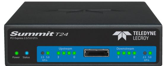
1.1.2Summit T24 Analyzer
The Teledyne LeCroy Summit T24 is Teledyne LeCroy’s high performance PCI Express analyzer for customers in server, workstation, desktop, graphics, storage and network card markets (see Figure 1.1 on page 3).
2 |
Summit T24 PCI Express Multi Lane Protocol Analyzer User Manual |
PETracer Analyzer Hardware and Software |
Teledyne LeCroy |
|
|
|
|
Figure 1.1: Summit T24 Analyzer
With advanced features such as data rates from 2.5 to 5.0 GBps, lane widths from x1 to x4, and 2 GB of memory, the Summit T24 provides unmatched capability and flexibility for developers and users of advanced PCI Express products.
As with other Teledyne LeCroy PCI Express analyzers, the Summit T24 leverages the intuitive and powerful CATC Trace analysis software system, embedding a deep understanding of the PCI Express protocol hierarchy and intricacies. The colorful, intuitive and easy to use graphical display allows you to quickly capture and validate PCI Express product designs.
An optional BitTracer™ mode allows bytes to be recorded as they come across the link, allowing debugging of PHY layer problems and combining the features of a logic analyzer format with a protocol analyzer format.
Features
Powerful and Intuitive CATC Trace Analysis Software System: The CATC Trace embeds deep understanding of the PCI Express protocol hierarchy and intricacies. This knowledge is presented in a colorful, intuitive and easy to use graphical display, allowing you to quickly capture and validate PCI Express product designs.
Protocol Hierarchical Viewing: Displays Packet, Transaction, Split, NVMe, PQI, AHCI and ATA command transactions levels of the PCI Express protocol, with increased drill down detail for PCI Express primitives, errors, payloads or individ ual packets.
Lane Reversal Compatible: Triggers, records, and displays PCI Express traffic log ically, regardless of the physical configuration of the lanes.
Statistical and Error Reporting: Provides a quick summary of the CATC Trace file to identify and track error rates and abnormal link or timing conditions.
BitTracer Recording Mode (optional): Records the bytes exactly as they come across the link, allowing debugging of PHY layer problems.
Auto Speed detection: Follows link transitions through speed changes.
Field upgradeable Firmware and Engine: Positions you to receive the latest PETracer enhancements and future additional capabilities. Allows field upgrades
Summit T24 PCI Express Multi Lane Protocol Analyzer User Manual |
3 |
Teledyne LeCroy |
PETracer Analyzer Hardware and Software |
|
|
of all system types.
2 GB Data Buffer: Capture long time windows for in depth analysis and identification of erratic problems.
USB connectivity: Allows connection by USB cable.
CrossSync Application: The CrossSync application allows you to select analyzers for synchronization and manage the recording process.
1.1.3Other Documents
For more information, refer to the following documents:
Teledyne LeCroy Analyzers File based Decoding Manual
PETracer/Trainer Automation Manual
PETracer VSE Manual
CrossSync Control Panel User Manual
4 |
Summit T24 PCI Express Multi Lane Protocol Analyzer User Manual |

Chapter 2
Hardware Description
The PCI Express™ system features Summit Analyzers.
2.1System Components
Summit T24™ analyzer system
DC Power Adaptor, 12 volts, and AC power cable
USB cable
PETracer Software program CD ROM
(optional) probes and interposers (see “Interposers and Probes” on page 11)
2.2Host Machine Requirements
The Summit T24 connects to a host machine. Please consult the readme file on the installation CD for the latest host machine requirements.
Summit T24 PCI Express Multi Lane Protocol Analyzer User Manual |
5 |

Teledyne LeCroy |
Summit T24 Front Panel Description |
|
|
2.3Summit T24 Front Panel Description
When powered on, the Summit T24 activates the user accessible controls and LEDs on the front panel.
WARNING: Do not open the enclosure. There are no operator serviceable parts inside. Refer servicing to Teledyne LeCroy.
The controls and LEDs are:
Power LED: Lights when power is On.
Status LED: Displays the connection status of the link.
Red Error condition. Try using the PETracer application to clear the error. Please contact the factory if this does not work.
Green Configuring system.
Purple Waiting for connection.
Blue - Unit ready/connected.
Speed LEDs: Indicates current speed the analyzer is using for the Upstream direction.
Upstream [3:0] LEDs: Indicates which Upstream Lanes are currently showing activity.
Upstream [3:0] and Downstream [3:0] connector: Connection to the probe for the capture of both upstream and downstream directions of the link.
Downstream [3:0] LEDs: Indicates which Downstream Lanes are currently show ing activity.
Speed LEDs: Indicates current speed the analyzer is using for the Downstream direction.
2.4Summit T24 Rear Panel Description
The Summit T24 rear panel contains:
USB Type B Host Machine Connector: To connect the Analyzer to the host machine using a USB connection.
Sync /Data: Allows multiple Teledyne LeCroy analyzers to send synchronization and control messages to one another. This is also used for Trigger in and Trigger Out. The minimal pulse width for Trigger In is 20ns.
DC IN: 12 V, 3 A
Power Switch (black): 1 = On and 0 = Off.
6 |
Summit T24 PCI Express Multi Lane Protocol Analyzer User Manual |

Chapter 3
Installation and Setup
The Summit T24™ is a standalone system.
You can begin PCI Express™ recordings after following the steps in this chapter.
3.1Installing the PETracer Software
PETracer software operates all of Teledyne LeCroy’s PCI Express protocol Analyzer and Exerciser products:
The PETracer software is installed on a Microsoft® Windows® based host machine and serves as the interface for the Exerciser and/or Analyzer.
To install the PETracer software on the host machine:
1.Insert the CD into the CD ROM drive of the host machine that controls the Analyzer. The installation window opens and displays links to the PETracer software, user manuals, a readme file, and Acrobat Reader.
2.Select Install Software and follow the onscreen instructions.
The PETracer software installs automatically on the host machine’s hard disk. During installation, all necessary drivers are loaded automatically.
3.To start the application, launch the PETracer program from the Start menu:
Start > Programs > LeCroy > PETracer > LeCroy PETracer
Summit T24 PCI Express Multi Lane Protocol Analyzer User Manual |
7 |

Teledyne LeCroy |
Installing the PETracer Software |
|
|
The PETracer program displays.
Figure 3.2: Teledyne LeCroy PETracer Application
Note:The software may be used with or without the Analyzer. When used without an Analyzer attached to the computer, the program functions as a CATC Trace Viewer to view, analyze, and print captured traffic.
8 |
Summit T24 PCI Express Multi Lane Protocol Analyzer User Manual |
Setting Up the Summit T24 Analyzer using a USB Connection |
Teledyne LeCroy |
|
|
|
|
3.2Setting Up the Summit T24 Analyzer using a USB Connection
To set up the Analyzer using a USB connection:
1.Connect the Analyzer to a 100 volt to 240 volt, 50 Hz to 60 Hz, 120 W power outlet using the provided power cord.
2.Connect the USB port to a USB port on the host machine using a USB cable.
3.Turn on the front power switch.
Note:At power on, the Analyzer initializes and performs a self diagnosis. The results are reflected by the Status LED.
4.Follow the Microsoft® Windows® on screen Plug and Play instructions for the automatic installation of the Analyzer as a USB device on your analyzing host machine. (The required USB drivers are installed on your system by the PETracer software installation.)
Click Finish when you see the message that says “Windows has finished installing the software that your new hardware requires” and the file has been installed in your host machine.
3.3Networking an Analyzer
PETracer™ has a networking capability that allows users to run an Analyzer remotely over an IP based LAN. Using the Network browse dialog, you can locate and connect to other host machines on the LAN, which, in turn, are connected to Analyzers. Through this connection, you can remotely control an Analyzer.
3.3.1Setup for IP LAN Use
In order to connect to a remote Analyzer, the Analyzer must be attached to a host machine that is on the LAN. This host machine must have PETracer installed.
Figure 3.3: Analyzer Attached to a host machine on the LAN
Summit T24 PCI Express Multi Lane Protocol Analyzer User Manual |
9 |
Teledyne LeCroy |
Analyzer Network |
|
|
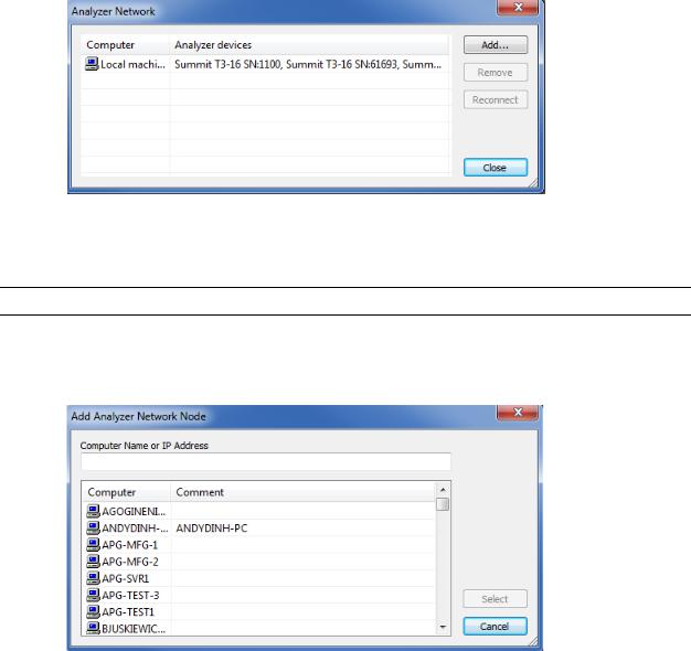
3.4Analyzer Network
For Ethernet, to display the host machines and analyzers on the local network, select Setup > Analyzer Network to display the Analyzer Network dialog.
Figure 3.4: Analyzer Network Dialog
The dialog displays the host machines on the network and the Analyzer devices connected to the host machines.
Note:The Analyzer must be turned on before it appears in the list.
You can click Add to display the Add Analyzer Network Node dialog, in which you can select a host machine on the network.
Figure 3.5: Add Analyzer Network Node Dialog
You can also Remove a selected host machine or Reconnect a selected host machine.
10 |
Summit T24 PCI Express Multi Lane Protocol Analyzer User Manual |
Interposers and Probes |
Teledyne LeCroy |
|
|
|
|
3.5Interposers and Probes
The Summit T24 works with Interposers and Probes. Some of them are listed below.
Gen2 MidBus Probe: The Gen2 MidBus Probe is designed for use with the Summit T24 Analyzer and supports lane widths from x1 to x4 at data rates of 2.5 GT/s (Gen1) or 5.0 GT/s (Gen2).
Gen2 Multi lead Probe: The Gen2 Multi lead Probe is designed for use with the Summit T24 Protocol Analyzer. The probe consists of 1 to 2 probe pods, which are connected to the analyzer using straight x4 iPass cables (for x4). Each probe pod supports up to 8 Flex Tips, with each Flex Tip connected via two coax cables.
Gen2 Passive Slot Interposer: The Gen2 passive Slot Interposer is designed for use with the Summit T24 Analyzer and supports lane widths from x1 to x4 at data rates of 2.5 GT/s (Gen1) or 5.0 GT/s (Gen2). For lane widths up to x4, one iPass straight cable is required.
Gen2 Active Slot Interposer: The Gen2 Active Slot Interposer when used on the Summit T24 will support lane widths from x1 to x4 at data rates of 2.5 GT/s (Gen1) or 5.0 GT/s (Gen2).
Please refer to the Interposers and Probes for Teledyne LeCroy PCI Express Systems datasheet at teledynelecroy.com for a comprehensive list.
The following sections describe how to set up probe systems.
3.6Using Interposers
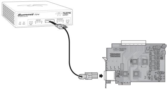
3.6.1Gen2 Passive Interposer
Figure 3.6: Connecting the Summit T24 Analyzer to the Device Under Test Using a
Gen2 Active Interposer
Summit T24 PCI Express Multi Lane Protocol Analyzer User Manual |
11 |

Teledyne LeCroy |
Using Interposers |
|
|
Summit T24 Components
Summit T24 components used in the installation are:
iPass x4 to x8 Straight cable: The cable supports four lanes from two directions but allows connection to x8 iPass connectors. The smaller x4 end plugs into the Summit T24 and the larger end plugs into the interposer
Summit T24 x4 Slot Gen2 Passive Interposer: The slot Interposer provides the point of attachment for the Analyzer to the Device Under Test (DUT). The Inter poser is designed to fit between a motherboard and one of its device cards for example, a LAN card. The Interposer has three sets of connectors: a gold male connector that fits into a standard x4 up to x16 PCI Express slot on a mother board, a PCIe female connector that accepts any PCI Express add in card. Although the PCIe female connector will accept up to x16 male connectors, only four lanes will be passed through the x4 interposer.
Note:If using X8 or X16 interposers, lane width reducers may be needed to analyze the link.
Installing the Gen2 Passive Interposer
To install the Interposer, perform the following steps.
1.Insert the gold male connector on the Interposer probe into a x4, x8 or
x16 PCI Express slot in the motherboard. If a X1 link is required, use edge adaptor for x1.
2.Insert the PCI Express DUT into the Interposer’s PCIe female device connector.
3.The slot Interposer is shipped from Teledyne LeCroy with a metal face plate for attachment to a PC case. If you are working with a motherboard that is not in a PC case, you may prefer to remove the metal face plate so the Interposer can sit flat with the motherboard. To remove the face plate, unscrew the two screws that hold it onto the Interposer
Power On Analyzer and then DUT
1.Power on the Summit T24 Analyzer.
2.Power on the DUT.
3.Open the PETracer software on the host machine. The Analyzer is now ready for PCI Express traffic recording.
12 |
Summit T24 PCI Express Multi Lane Protocol Analyzer User Manual |
Using Probes |
Teledyne LeCroy |
|
|
|
|
3.7Using Probes
3.7.1Example: Connecting the Summit T24 Analyzer to the Device Under Test Using a Gen2 MidBus Probe
Note:Mid bus probes require attachment pad and reference clock connections. For information about how to connect the attachment pad, reference clock, and cables in your system, see the
MidBus Probe Manual.
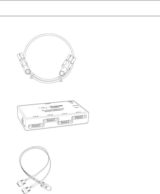
Components
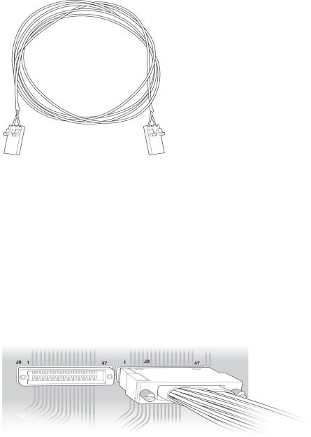
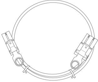
Figure 3.7: iPass x4 to x8 Straight Cable
Figure 3.8: Gen2 Mid-bus Probe Pod for Summit T24
Figure 3.9: Half-size Gen2 Mid-bus Probe Cable and Header Assembly |
|
Summit T24 PCI Express Multi Lane Protocol Analyzer User Manual |
13 |
Teledyne LeCroy |
Using Probes |
|
|
Figure 3.10: Clock Cable
Connections Overview for Gen2 MidBus Probe
Use a 1 pod setup.
Use the iPass x4 to x8 Straight cable to connect the probe data connectors on the Analyzer to the MidBus pod(s).
On the other side of the pod, connect the MidBus probe assembly.
Connect the header on the MidBus probe assembly to the MidBus footprint on the System Under Test (host platform/root complex). The following picture shows two midbus footprints, with one connected to the MidBus probe assembly.
Figure 3.11: Connect MidBus Probe to MidBus Footprint
Connection Procedure
To connect the Summit T24 to the System Under Test (host platform/root complex):
1.Connect the MidBus pods to the Analyzer using the iPass x4 to x8 Straight cable.
2.Connect the MidBus probe assemblies to the MidBus pods.
3.Connect the MidBus probe assemblies to the MidBus footprints on the system under test.
4.Connect external reference clock signal to Mid Bus External Clock In on Mid Bus probe pod, using external reference clock cable.
14 |
Summit T24 PCI Express Multi Lane Protocol Analyzer User Manual |
Using Probes |
Teledyne LeCroy |
|
|
|
|
3.7.2Example: Connecting the Summit T24 Analyzer to the Device Under Test Using a Gen2 Multi-lead Probe for x1 and x4
Components
iPass x4 to x8 Straight cable for x1 and x4 (see “iPass x4 to x8 Straight Cable” on page 13).
1 Multi lead Probe Pod for x1 and x4
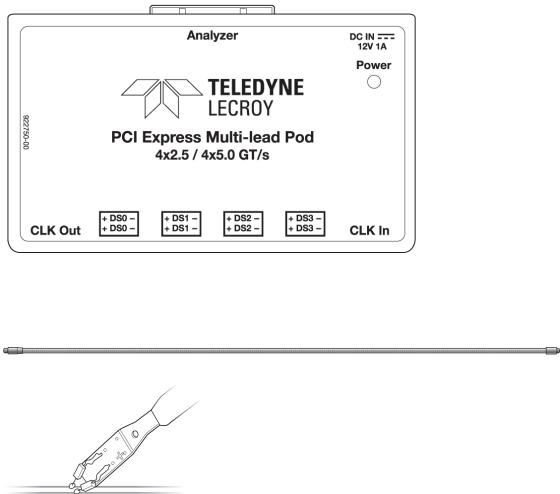
Figure 3.12: Multi-Lead Probe Pod
Up to 16 MidBus Probe SSMP Cables, and up to 8 Flexible Leads, per pod
Figure 3.13: Midbus Probe SSMP Cables
1 Clock Cable (see Figure 3.10 on page 14).
Connections for Gen2 Multi-lead Probe
Overview
Use a 1 pod setup.
For x1 or x4, use the iPass x4 to x8 Straight cable to connect the probe data connectors on the Analyzer to the pod(s).
On the other side of the pod, connect the flexible lead tips.
Summit T24 PCI Express Multi Lane Protocol Analyzer User Manual |
15 |
Teledyne LeCroy |
Using Probes |
|
|
Connection Procedure
To connect Summit T24 to the System Under Test (host platform/root complex):
1.Connect the pods to the Analyzer using the iPass x4 to x8 Straight cable.
2.Connect the flexible lead tips to the pods using the SSMP cables.
3.Connect the lead tips to the system under test by soldering to the trace.
3.7.3Example: Connecting the Summit T24 Analyzer to the Device Under Test Using a Gen2 Multi-lead Probe for x4
Components
1 iPass x4 to x8 Straight cable for x4
Figure 3.14: iPass x4 to x8 Straight cable
2 Multi lead Probe pods for x4
(See “1 Multi lead Probe Pod for x1 and x4” on page 15).
Up to 16 MidBus Probe SSMP Cables, and up to 8 Flexible Leads, per pod. (See Figure 3.12 on page 15).
1 Clock Cable (see Figure 3.9 on page 13).
Connections Overview for Gen2 Multi-lead Probe
Use a 1 pod setup.
For x4, use the straight iPass cable to connect the probe data connectors on the Analyzer to the pod(s).
On the other side of the pod, connect the flexible lead tips.
Connection Procedure
To connect Summit T24 to the system under test (host platform/root complex): 1. Connect the pods to the Analyzer using the straight iPass cables.
16 |
Summit T24 PCI Express Multi Lane Protocol Analyzer User Manual |
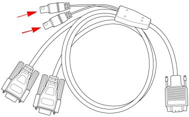
Using Probes |
Teledyne LeCroy |
|
|
|
|
2.Connect the flexible lead tips to the pods using the SSMP cables.
3.Connect the lead tips to the system under test by soldering to the trace.
MicroD to CATC Sync Cable
The cable is used to synchronize the T24 with other Teledyne Lecroy systems. It also provides a way to supply input and output triggers. Use the two connectors shown below.
Figure 3.15: MicroD to CATC Sync Cable
Summit T24 PCI Express Multi Lane Protocol Analyzer User Manual |
17 |
Teledyne LeCroy |
Using Probes |
|
|
18 |
Summit T24 PCI Express Multi Lane Protocol Analyzer User Manual |
Loading...