


 Loading...
Operation Manual
Model 100E
UV Fluorescence SO2 Analyzer
Also supports operation of: |
when used in conjunction with: |
M100EU Analyzer |
M100EU Addendum, PN05831 |
M100EH Analyzer |
M100EH Addendum, PN 04621 |
M108E Analyzer |
M108E Addendum, PN 03940 |
M108EU Analyzer |
M108E Addendum, PN03949 and |
|
M100EU Addendum, PN 04621 |
© TELEDYNE ADVANCED POLLUTION INSTRUMENTATION
9480 CARROLL PARK DRIVE
SAN DIEGO, CA 92121-5201
USA
Toll-free Phone: 800-324-5190
Phone: 858-657-9800
Fax: 858-657-9816
Email: api-sales@teledyne.com
Website: http://www.teledyne-api.com/
Copyright 2008 - 2011 |
04515F DCN6048 |
Teledyne Advanced Pollution Instrumentation |
06 April 2011 |

ABOUT THIS MANUAL
This M100E manual, PN 04515, is comprised of the following documents:
Part No. |
Rev |
Name/Description |
04515 |
F |
M100E Operation Manual (main content) |
05036 |
E |
Appendix A, Menu Trees and related software documentation, Rev G.4. |
05360 |
Q |
Spare Parts List (in Appendix B of this manual) |
04526 |
S |
Recommended Spare Parts Stocking Levels (in Appendix B of this manual) |
04728 |
A |
AKIT, Spares (in Appendix B of this manual) |
04357 |
A |
AKIT, Expendables (in Appendix B of this manual) |
01475 |
A |
AKIT, Expendables for IZS option (in Appendix B of this manual) |
04796 |
E |
Appendix C, Test Funct & Repair Qstnr |
0401101 |
A |
Interconnect List, M100E (in Appendix D of this manual) |
04011 |
A |
Interconnect Diagram, M100E (in Appendix D of this manual) |
04354 |
D |
PCA, 04003, Pressure Flow Sensor Board (in Appendix D of this manual) |
04524 |
D |
Schematic, Relay PCB (in Appendix D of this manual) |
05703 |
A |
PCA, 05702, Motherboard, E-Series Gen 4 (in Appendix D of this manual) |
04181 |
H |
PCA, 04180, PMT Preamp (in Appendix D of this manual) |
04259 |
A |
PCA, 04258, Keyboard Display Interface (in Appendix D of this manual) |
05064 |
C |
PCA, 05063, Dual UV Detector (in Appendix D of this manual) |
04693 |
E |
PCA, 04692, UV Lamp Driver (in Appendix D of this manual) |
|
|
|
04932 |
C |
PCA, Thermo-Electric Cooler Board (in Appendix D of this manual) |
04468 |
B |
PCA, 04467, Analog Output Series Res (in Appendix D of this manual) |
NOTE
Please read this manual in its entirety before operating the instrument.
04515F DCN6048 |
i |

Table of Contents Teledyne API M100E Analyzer Operation Manual
REVISION HISTORY
M100E Operation Manual, PN04515
Document |
PN |
Rev |
DCN |
Change Summary |
2011 April 06, Rev F, DCN6048 |
|
|
|
|
M100E Operation |
04515 |
F |
6048 |
Administrative corrections in Revision History |
Manual |
|
|
|
section: typos. |
2011 March 11, Rev E, DCN6019 |
|
|
||
M100E Operation |
04515 |
E |
6019 |
Combine with M100E “Text” (PN05138) for single |
Manual |
|
|
|
document/PN; obsolete 05138. |
|
|
|
|
Change Disk-on-Module replacement procedure |
|
|
|
|
from A-Crosser to ICOP CPU (Mntnc section) |
|
|
|
|
Add MODBUS quick setup to Remote Op section |
|
|
|
|
Add desiccant bag change to maintenance sched. |
2009 Dec 15, M100E Manual, PN045150100 Rev D, DCN5637 |
||||
Top Assy Manual |
045150100 |
D |
5637 |
Initial development of this manual’s top assy |
|
|
|
|
construct, which is the fully assembled manual |
|
|
|
|
comprised of the PDF conversions of all documents |
|
|
|
|
listed in the About This Manual section. Revision |
|
|
|
|
starts at “D” to be in step with Rev History of original |
|
|
|
|
manual. |
Title/front matter |
04515 |
D |
5637 |
Show current Rev letter of all documents comprising |
|
|
|
|
the top assy of this manual (in About This Manual). |
|
|
|
|
Initiate Revision History |
Text |
05138 |
C |
5637 |
Insert new CPU information in place of old, Sections |
|
|
|
|
11.4.1 11.4.1.1 and 11.4.1.2 and new Fig 11-11. |
|
|
|
|
Replace all occurrences of disk-on-chip (DOC) with |
|
|
|
|
disk-on-module (DOM). |
|
|
|
|
Replace illustrations Fig 5-2, 5-6, 5-7, 5-8, 7-5. 7-12, |
|
|
|
|
for greater detail and/or clarity. |
|
|
|
|
Revise RS-485 configuration instructions, Sec. 7.1.4, |
|
|
|
|
to reflect new CPU. |
|
|
|
|
Revise Multidrop RS-232 Set-up Instructions, Sec |
|
|
|
|
7.1.7, to reflect E-series parameters. |
|
|
|
|
Add desiccant bag replacement to maintenance |
|
|
|
|
requirements (per DCR 6559) |
For the purpose of capturing this manual’s construct with its initial Revision History implementation, the following list documents the current Rev of each part comprising this manual at Rev D; any future changes to these documents will be recorded in the Revision History section and their Rev letters updated in the About This Manual section:
Title |
04515 |
D |
|
|
|
|
|
|
|
Text |
05138 |
C |
|
|
Relay PCA Addend. |
05118 |
B3 |
|
|
S/W (Rev G.3) (AppxA) |
05036 |
D |
|
|
ii |
04515F DCN6048 |

Teledyne API M100E Analyzer Operation Manual Table of Contents
Document |
PN |
Rev |
DCN |
Change Summary |
SPL |
05360 |
Q |
|
|
RSSL |
04526 |
S |
|
|
|
|
|
|
|
AKIT, Spares |
04728 |
A |
|
|
|
|
|
|
|
AKIT, Expendables |
04357 |
A |
|
|
AKIT, Expendables, IZS |
01475 |
A |
|
|
Repair Request (AppxC) |
04796 |
D |
|
|
Interconnect List |
0401101 |
A |
|
|
|
|
|
|
|
Interconnect Diagram |
04011 |
A |
|
|
|
|
|
|
|
PCA04003PressFlwSnsr |
04354 |
D |
|
|
PCB,Relay |
04524 |
D |
|
|
PCA05702MoBrd |
05703 |
A |
|
|
PCA04180PMT Preamp |
04181 |
H |
|
|
|
|
|
|
|
PCA04258Kybrd Int |
04259 |
A |
|
|
|
|
|
|
|
PCA05063 UVDetect |
05064 |
C |
|
|
PCA04692 LmpDrvr |
04693 |
E |
|
|
PCA ThermCooler |
04932 |
C |
|
|
PCA Analog Outpt |
04468 |
B |
|
|
|
|
|
|
|
04515F DCN6048 |
iii |

Table of Contents |
Teledyne API M100E Analyzer Operation Manual |
This page intentionally left blank.
iv |
04515F DCN6048 |

TABLE OF CONTENTS |
|
SECTION I GENERAL INFORMATION .................................................................................. |
13 |
1. INTRODUCTION ................................................................................................................ |
15 |
1.1. Safety Messages........................................................................................................................................... |
15 |
1.2. M100E Overview........................................................................................................................................... |
16 |
1.3. M100E Documentation.................................................................................................................................. |
16 |
1.3.1. Using This Manual ................................................................................................................................. |
17 |
2. SPECIFICATIONS, APPROVALS AND WARRANTY ....................................................... |
19 |
2.1. Specifications ................................................................................................................................................ |
19 |
2.2. EPA Equivalency Designation ...................................................................................................................... |
20 |
2.3. CE Mark Compliance .................................................................................................................................... |
21 |
2.3.1. Emissions Compliance........................................................................................................................... |
21 |
2.3.2. Safety Compliance................................................................................................................................. |
21 |
2.4. Warranty........................................................................................................................................................ |
21 |
3. GETTING STARTED .......................................................................................................... |
23 |
3.1. M100E Analyzer Layout ................................................................................................................................ |
23 |
3.2. Unpacking the M100E Analyzer.................................................................................................................... |
27 |
3.3. Electrical Connections................................................................................................................................... |
28 |
3.3.1. Power Connection.................................................................................................................................. |
28 |
3.3.2. Analog Output Connections.................................................................................................................. |
29 |
3.3.3. Connecting the Status Outputs.............................................................................................................. |
29 |
3.3.4. Connecting the Control Inputs ............................................................................................................... |
31 |
3.3.5. Connecting the Serial Ports ................................................................................................................... |
32 |
3.3.6. Connecting to a LAN or the Internet ...................................................................................................... |
32 |
3.3.7. Connecting to a Multidrop Network........................................................................................................ |
32 |
3.4. Pneumatic Connections ................................................................................................................................ |
32 |
3.4.1. Calibration Gases .................................................................................................................................. |
32 |
3.5. Initial Operation ............................................................................................................................................. |
36 |
3.6. Initial Calibration of the M100E ..................................................................................................................... |
42 |
3.6.1. Interferents for Measurements............................................................................................................... |
42 |
3.6.2. Initial Calibration Procedure for M100E Analyzers without Options ...................................................... |
43 |
3.6.3. O2 Sensor Calibration Procedure........................................................................................................... |
47 |
3.6.4. CO2 Sensor Calibration Procedure ........................................................................................................ |
47 |
4. FREQUENTLY ASKED QUESTIONS & GLOSSARY ....................................................... |
49 |
4.1. FAQ’s ............................................................................................................................................................ |
49 |
4.2. Glossary ........................................................................................................................................................ |
51 |
5. OPTIONAL HARDWARE AND SOFTWARE ..................................................................... |
53 |
5.1. Optional Pumps (OPT 10 to OPT 13) ........................................................................................................... |
53 |
5.2. Rack Mount Kits (OPT 20A, OPT 20B, OPT 21, OPT 23)............................................................................ |
53 |
5.3. Carrying Strap/Handle (OPT 29)................................................................................................................... |
54 |
5.4. Current Loop Analog Outputs (Option 41) .................................................................................................... |
54 |
5.5. Optional Kits (OPT 42A, OPT 43, OPT 45)................................................................................................... |
56 |
5.6. NO Optical Filter (OPT 47B) ......................................................................................................................... |
56 |
5.7. Calibration Valves Options............................................................................................................................ |
56 |
5.8. Communication Options................................................................................................................................ |
60 |
5.8.1. RS-232 Modem Cable (OPT 60A, OPT 60B, OPT 60C) ....................................................................... |
60 |
5.8.2. Concentration Alarm Relay (Option 61)................................................................................................. |
60 |
5.8.3. RS-232 Multidrop (Option 62)................................................................................................................ |
61 |
5.8.4. Ethernet (Option 63A) ............................................................................................................................ |
62 |
5.8.5. Ethernet + Multidrop (OPT 63C) ............................................................................................................ |
63 |
5.9. Second Gas Sensors .................................................................................................................................... |
63 |
5.9.1. Oxygen Sensor (Option 65A)................................................................................................................. |
63 |
5.9.2. Carbon Dioxide Sensor (Option 67A) .................................................................................................... |
65 |
5.10. Additional Manuals...................................................................................................................................... |
68 |
5.11. Extended Warranty (OPT 92B and OPT 93C)............................................................................................ |
68 |
04515F DCN6048 |
v |

Table of Contents |
Teledyne API M100E Analyzer Operation Manual |
|
5.12. Special Features ......................................................................................................................................... |
|
69 |
SECTION II OPERATING INSTRUCTIONS............................................................................ |
|
71 |
6. OPERATING INSTRUCTIONS........................................................................................... |
|
73 |
6.1. Overview of Operating Modes ...................................................................................................................... |
|
73 |
6.2. Sample Mode ................................................................................................................................................ |
|
74 |
6.3. Calibration Mode ........................................................................................................................................... |
|
78 |
6.4. Setup Mode................................................................................................................................................... |
|
80 |
6.5. SETUP – CFG: Viewing the Analyzer’s Configuration Information .............................................................. |
82 |
|
6.6. SETUP – CLK: Setting the Internal Time-of-Day Clock................................................................................ |
|
83 |
6.7. SETUP – RNGE: Analog Output Reporting Range Configuration................................................................ |
85 |
|
6.8. SETUP – VARS: Using the Internal Variables.............................................................................................. |
|
93 |
6.9. SETUP – DIAG: Using the Diagnostics Functions........................................................................................ |
|
95 |
7. REMOTE OPERATION AND ADVANCED FEATURES .................................................. |
119 |
|
7.1. SETUP – COMM: Setting Up the Analyzer’s Communication Ports.......................................................... |
119 |
|
7.1.3. RS-232 COM Port Cable Connections ............................................................................................... |
|
121 |
7.1.4. RS-485 Configuration of COM2.......................................................................................................... |
|
122 |
7.1.6. Ethernet Card Configuration ............................................................................................................... |
|
124 |
7.1.7. MODBUS Setup.................................................................................................................................. |
|
131 |
7.1.8. Multidrop RS-232 Set Up .................................................................................................................... |
|
133 |
7.2. Using the Internal Data Acquisition System (iDAS) ................................................................................... |
|
139 |
7.3. Remote Operation...................................................................................................................................... |
|
158 |
8. CALIBRATION PROCEDURES ....................................................................................... |
|
175 |
8.1. Calibration Preparations............................................................................................................................. |
|
175 |
8.2. Manual Calibration ..................................................................................................................................... |
|
177 |
8.3. Manual Calibration Checks ........................................................................................................................ |
|
179 |
8.4. Manual Calibration with Zero/Span Valves ................................................................................................ |
|
180 |
8.5. Manual Calibration with IZS Option ........................................................................................................... |
|
182 |
8.6. Manual Calibration Checks with IZS or Zero/Span Valves ........................................................................ |
|
183 |
8.7. Manual Calibration in DUAL or AUTO Reporting Range Modes ............................................................... |
185 |
|
8.8. Automatic Calibration (AutoCal)................................................................................................................. |
|
186 |
8.9. Calibration Quality...................................................................................................................................... |
|
189 |
8.10. Calibration of Optional Sensors ............................................................................................................... |
|
189 |
8.10.1. O2 Sensor Calibration Procedure...................................................................................................... |
|
189 |
8.10.2. CO2 Sensor Calibration Procedure................................................................................................... |
|
193 |
9. EPA PROTOCOL CALIBRATION.................................................................................... |
|
197 |
9.1. Calibration Requirements........................................................................................................................... |
|
197 |
9.2. Level 1 Calibrations versus Level 2 Checks .............................................................................................. |
|
201 |
9.3. ZERO and SPAN Checks .......................................................................................................................... |
|
202 |
9.4. Precisions Calibration Procedures and Checks......................................................................................... |
|
202 |
9.5. Dynamic Multipoint Span Calibration ......................................................................................................... |
|
203 |
9.6. Special Calibration Requirements for Dual Range or Auto Range............................................................ |
204 |
|
9.7. References................................................................................................................................................. |
|
204 |
SECTION III TECHNICAL INFORMATION........................................................................... |
|
205 |
10. INSTRUMENT MAINTENANCE .................................................................................... |
|
207 |
10.1. Maintenance Schedule............................................................................................................................. |
|
209 |
10.2. Predictive Diagnostics.............................................................................................................................. |
|
211 |
10.3. Maintenance Procedures ......................................................................................................................... |
|
212 |
10.3.7. Performing a Sample Flow Check .................................................................................................... |
|
216 |
10.3.8. Hydrocarbon Scrubber (Kicker) ........................................................................................................ |
|
216 |
11. THEORY OF OPERATION ............................................................................................ |
|
219 |
11.1. Measurement Principle ............................................................................................................................ |
|
219 |
11.1.1. SO2 Ultraviolet Fluorescence............................................................................................................ |
|
219 |
11.2. The UV Light Path.................................................................................................................................... |
|
222 |
11.2.1. UV Source Lamp............................................................................................................................... |
|
223 |
11.2.2. The Reference Detector.................................................................................................................... |
|
223 |
11.2.3. The PMT ........................................................................................................................................... |
|
223 |
vi |
04515F DCN6048 |

Teledyne API M100E Analyzer Operation Manual |
Table of Contents |
11.2.4. UV Lamp Shutter & PMT Offset........................................................................................................ |
223 |
11.2.5. Optical Filters .................................................................................................................................... |
224 |
11.3. Pneumatic Operation ............................................................................................................................... |
228 |
11.3.4. Hydrocarbon Scrubber (Kicker) ........................................................................................................ |
231 |
11.4. Electronic Operation................................................................................................................................. |
233 |
11.5. Power Supply and Circuit Breaker ........................................................................................................... |
247 |
11.6. Communications Interface ....................................................................................................................... |
248 |
11.7. Software Operation .................................................................................................................................. |
252 |
12. TROUBLESHOOTING & REPAIR................................................................................. |
255 |
12.1. General Troubleshooting.......................................................................................................................... |
255 |
12.1.2. Fault Diagnosis with Test Functions ................................................................................................. |
258 |
12.2. Status LEDs ............................................................................................................................................. |
261 |
12.2.1. Motherboard Status Indicator (Watchdog)........................................................................................ |
261 |
12.2.2. CPU Status Indicators....................................................................................................................... |
261 |
12.2.3. Relay Board Status LEDs ................................................................................................................. |
262 |
12.3. Gas Flow Problems.................................................................................................................................. |
263 |
12.4. Calibration Problems................................................................................................................................ |
264 |
12.5. Other Performance Problems .................................................................................................................. |
267 |
12.6. Subsystem Checkout ............................................................................................................................... |
269 |
12.6.8. RS-232 Communication.................................................................................................................... |
274 |
12.7. Repair Procedures ................................................................................................................................... |
279 |
12.7.1. Disk-on-Module (DOM) Replacement............................................................................................... |
279 |
12.8. Technical Assistance ............................................................................................................................... |
293 |
13. A PRIMER ON ELECTRO-STATIC DISCHARGE......................................................... |
295 |
13.1. How Static Charges are Created ............................................................................................................. |
295 |
13.2. How Electro-Static Charges Cause Damage........................................................................................... |
296 |
13.3. Common Myths About ESD Damage ...................................................................................................... |
297 |
13.4. Basic Principles of Static Control ............................................................................................................. |
298 |
13.4.1. General Rules ................................................................................................................................... |
298 |
13.5. Basic anti-ESD Procedures for Analyzer Repair and Maintenance......................................................... |
299 |
13.5.1. Working at the Instrument Rack ....................................................................................................... |
299 |
13.5.2. Working at an Anti-ESD Work Bench ............................................................................................... |
299 |
13.5.3. Transferring Components from Rack to Bench and Back ................................................................ |
300 |
13.5.4. Opening Shipments from Teledyne API’s Customer Service........................................................... |
300 |
13.5.5. Packing Components for Return to Teledyne API’s Customer Service ........................................... |
301 |
INDEX ................................................................................................................................ |
303 |
APPENDIX A – MENU TREES and VERSION SPECIFIC SOFTWARE DOCUMENTATION APPENDIX B - SPARE PARTS, M100E
APPENDIX C - REPAIR QUESTIONNAIRE, M100E
APPENDIX D - ELECTRONIC SCHEMATICS, M100E
LIST OF FIGURES
Figure 3-1: |
Front Panel Layout....................................................................................................................... |
23 |
Figure 3-2: |
Rear Panel Layout ....................................................................................................................... |
24 |
Figure 3-3: |
M100E Layout (Basic Unit – No Valve Options).......................................................................... |
25 |
Figure 3-4: |
M100E Internal Gas Flow (Basic Configuration) ......................................................................... |
26 |
Figure 3-5: |
Analog Output Connector ............................................................................................................ |
29 |
Figure 3-6: |
Status Output Connector ............................................................................................................. |
30 |
Figure 3-7: |
Control Input Connector............................................................................................................... |
31 |
Figure 3-8: |
Pneumatic Connections–Basic Configuration–Using Bottled Span Gas..................................... |
34 |
Figure 3-9: |
Pneumatic Connections–Basic Configuration–Using Gas Dilution Calibrator............................. |
35 |
Figure 3-10: |
Startup – Front Panel Display...................................................................................................... |
37 |
Figure 3-11: |
Warning Messages ...................................................................................................................... |
38 |
04515F DCN6048 |
|
vii |

Table of Contents |
Teledyne API M100E Analyzer Operation Manual |
|
Figure 3-12: |
Functional Check ......................................................................................................................... |
41 |
Figure 3-13: |
Reporting Range Verification....................................................................................................... |
43 |
Figure 3-14: |
Dilution Ratio Setup ..................................................................................................................... |
44 |
Figure 3-15: |
SO2 Span Gas Setting ................................................................................................................. |
45 |
Figure 3-16: |
Zero/Span Calibration Procedure ................................................................................................ |
46 |
Figure 5-1: |
Carrying Strap Handle and Rack Mount Brackets....................................................................... |
54 |
Figure 5-2: |
Current Loop Option Installed on the Motherboard ..................................................................... |
55 |
Figure 5-3: |
Pneumatic Diagram of the M100E with Z/S Option Installed....................................................... |
57 |
Figure 5-4: |
Pneumatic Diagram of the M100E with IZS Options Installed..................................................... |
58 |
Figure 5-5: |
Concentration Alarm Relay.......................................................................................................... |
60 |
Figure 5-6: |
Multidrop Card Seated on CPU above Disk on Module .............................................................. |
62 |
Figure 5-7: |
Ethernet Card............................................................................................................................... |
62 |
Figure 5-8: |
Rear Panel with Ethernet Installed .............................................................................................. |
63 |
Figure 5-9: |
Oxygen Sensor - Theory of Operation......................................................................................... |
64 |
Figure 5-10: |
Internal Pneumatics with O2 Sensor ............................................................................................ |
65 |
Figure 5-11: |
CO2 Sensor Theory of Operation................................................................................................. |
66 |
Figure 5-12: |
Internal Pneumatics with CO2 ...................................................................................................... |
67 |
Figure 5-13: |
CO2 Sensor Option PCA Layout and Electronic Connections..................................................... |
68 |
Figure 6-1: |
Front Panel Display...................................................................................................................... |
73 |
Figure 6-2: |
Viewing M100E TEST Functions ................................................................................................. |
76 |
Figure 6-3: |
Viewing and Clearing M100E WARNING Messages .................................................................. |
77 |
Figure 6-4: |
SETUP – Enable Calibration Password Security ........................................................................ |
79 |
Figure 6-5: |
SETUP – Enter Calibration Mode Using Password..................................................................... |
80 |
Figure 6-6: |
SETUP – Configuration Information ............................................................................................ |
82 |
Figure 6-7: |
SETUP – Clock ............................................................................................................................ |
83 |
Figure 6-8: |
SETUP – Clock Speed Variable .................................................................................................. |
84 |
Figure 6-9: |
SETUP – Analog Output Connector Key ..................................................................................... |
85 |
Figure 6-10: |
SETUP RNGE – Reporting Range Mode .................................................................................... |
87 |
Figure 6-11: |
SETUP RNGE – Single Range Mode.......................................................................................... |
88 |
Figure 6-12: |
SETUP RNGE – Dual Range Mode ............................................................................................ |
89 |
Figure 6-13: |
SETUP RNGE – Auto Range Mode ............................................................................................ |
90 |
Figure 6-14: |
SETUP RNGE – Concentration Units Selection.......................................................................... |
91 |
Figure 6-15: |
SETUP RNGE – Dilution Ratio .................................................................................................... |
92 |
Figure 6-16: |
SETUP – VARS Menu ................................................................................................................. |
94 |
Figure 6-17: |
DIAG Menu .................................................................................................................................. |
96 |
Figure 6-18: |
DIAG – Signal I/O Menu .............................................................................................................. |
97 |
Figure 6-19: |
DIAG – Analog Output Menu ....................................................................................................... |
98 |
Figure 6-20: |
DIAG – Analog I/O Configuration Menu.................................................................................... |
101 |
Figure 6-21: |
DIAG – Analog Output Calibration Mode.................................................................................. |
102 |
Figure 6-22: |
DIAG – Analog Output Calibration Mode – Single Analog Channel......................................... |
103 |
Figure 6-23: |
DIAG – Analog Output – Auto Cal or Manual Cal Selection for Channels ............................... |
104 |
Figure 6-24: |
Setup for Calibrating Analog Outputs ....................................................................................... |
105 |
Figure 6-25: |
Analog Output – Voltage Adjustment........................................................................................ |
106 |
Figure 6-26: |
Analog Output – Offset Adjustment .......................................................................................... |
107 |
Figure 6-27: |
Setup for Calibrating Current Outputs ...................................................................................... |
108 |
Figure 6-28: |
Analog Output – Zero and Span Value Adjustment for Current Outputs.................................. |
109 |
Figure 6-29: |
DIAG – Analog Output – AIN Calibration.................................................................................. |
110 |
Figure 6-30: |
DIAG – Optic Test..................................................................................................................... |
111 |
Figure 6-31: |
DIAG – Electrical Test............................................................................................................... |
112 |
Figure 6-32: |
DIAG – Lamp Calibration.......................................................................................................... |
113 |
Figure 6-33: |
DIAG – Pressure Calibration .................................................................................................... |
114 |
Figure 6-34: |
DIAG – Flow Calibration ........................................................................................................... |
115 |
Figure 6-35: |
DIAG – Test Channel Output.................................................................................................... |
116 |
Figure 7-1: |
SETUP – COMM Menu............................................................................................................. |
119 |
Figure 7-2: |
COMM – Analyzer ID ............................................................................................................... |
120 |
Figure 7-3: |
Back Panel Connector Pin-Outs for RS-232 and COM2 in RS-232 Mode............................... |
121 |
Figure 7-4: |
CPU Connector Pin-Outs for RS-232 and COM2 in RS-232 Mode.......................................... |
122 |
Figure 7-5: |
CPU RS-485 Setup................................................................................................................... |
123 |
viii |
04515F DCN6048 |
Teledyne API M100E Analyzer Operation Manual |
Table of Contents |
|||
Figure 7-6: |
Rear Panel Connector Pin-Outs for COM2 in RS-485 Mode ................................................... |
123 |
||
Figure 7-7: |
CPU Connector Pin-Outs for COM2 in RS-485 Mode.............................................................. |
124 |
||
Figure 7-8: |
COMM – LAN / Internet Configuration Properties .................................................................... |
127 |
||
Figure 7-9: |
COMM – Manually Configuring the Network IP Addresses (Step 1)........................................ |
128 |
||
Figure 7-10: |
COMM – Manually Configuring the Network IP Addresses (Step 2)........................................ |
129 |
||
Figure 7-11: |
COMM – Change Host Name.................................................................................................. |
130 |
||
Figure 7-12: |
Location of JP2 on RS232-Multidrop PCA (OPT 62)................................................................ |
133 |
||
Figure 7-13: |
RS232-Multidrop PCA Host/Analyzer Interconnect Diagram ................................................... |
134 |
||
Figure 7-14: |
COMM – Enable Hessen Protocol (Example) .......................................................................... |
136 |
||
Figure 7-15: |
COMM – COMM Port Baud Rate ............................................................................................. |
137 |
||
Figure 7-16: |
COMM – COMM Port Baud Rate ............................................................................................. |
138 |
||
Figure 7-17: |
Default iDAS Channels Setup................................................................................................... |
143 |
||
Figure 7-18: |
iDAS – Data Acquisition Menu................................................................................................. |
144 |
||
Figure 7-19: |
iDAS – Editing iDAS Data Channels........................................................................................ |
145 |
||
Figure 7-20: |
iDAS – Editing Data Channel Name ........................................................................................ |
146 |
||
Figure 7-21: |
iDAS |
– Trigger Events ............................................................................................................. |
147 |
|
Figure 7-22: |
iDAS – Editing iDAS Parameters............................................................................................. |
148 |
||
Figure 7-23: |
iDAS |
– Configuring Parameters for a Specific Data Parameter .............................................. |
149 |
|
Figure 7-24: |
iDAS |
– Define the Report Period ............................................................................................. |
151 |
|
Figure 7-25: |
iDAS |
– Define the Report Period ............................................................................................. |
152 |
|
Figure 7-26: |
iDAS – RS-232 Report Function.............................................................................................. |
153 |
||
Figure 7-27: |
iDAS |
– Disabling / Enabling Data Channels............................................................................ |
154 |
|
Figure 7-28: |
iDAS |
– Holdoff Feature............................................................................................................ |
155 |
|
Figure 7-29: |
Sample APICOM User Interface for Configuring the iDAS....................................................... |
156 |
||
Figure 7-30: |
iDAS Configuration Through a Terminal Emulation Program................................................... |
157 |
||
Figure 7-31: |
Status Output Connector .......................................................................................................... |
158 |
||
Figure 7-32: |
Control Inputs with Local 5 V Power Supply............................................................................. |
160 |
||
Figure 7-33: |
Control Inputs with External 5 V Power Supply ........................................................................ |
160 |
||
Figure 7-34: |
COMM – Remote Access by Modem ....................................................................................... |
164 |
||
Figure 7-35: |
COMM – Initialize the Modem .................................................................................................. |
165 |
||
Figure 7-36: |
APICOM Remote Control Program Interface............................................................................ |
167 |
||
Figure 7-37: |
COMM – Activating Hessen Protocol ....................................................................................... |
169 |
||
Figure 7-38: |
COMM – Select Hessen Protocol Type .................................................................................... |
170 |
||
Figure 7-39: |
COMM – Select Hessen Protocol Response Mode.................................................................. |
171 |
||
Figure 7-40: |
COMM – Status Flag Bit Assignment ....................................................................................... |
173 |
||
Figure 8-1: |
Setup for Manual Calibration without Z/S Valve or IZS Option (Step 1)................................... |
177 |
||
Figure 8-2: |
Setup for Manual Calibration without Z/S Valve or IZS Option (Step 2)................................... |
177 |
||
Figure 8-3: |
Setup for Manual Calibration without Z/S Valve or IZS Option (Step 3)................................... |
178 |
||
Figure 8-4: |
Setup for Manual Calibration Checks ....................................................................................... |
179 |
||
Figure 8-5: |
Setup for Manual Calibration with Z/S Valve Option Installed (Step 1) .................................... |
180 |
||
Figure 8-6: |
Setup for Manual Calibration with Z/S Valve Option Installed (Step 2) .................................... |
180 |
||
Figure 8-7: |
Setup for Manual Calibration with Z/S Valve Option Installed (Step 3) .................................... |
181 |
||
Figure 8-8: |
Manual Calibration with IZS Option .......................................................................................... |
182 |
||
Figure 8-9: |
Setup for Manual Calibration Check with Z/S Valve or IZS Option (Step 1) ............................ |
183 |
||
Figure 8-10: |
Setup for Manual Calibration Check with Z/S Valve or IZS Option (Step 2) ............................ |
184 |
||
Figure 8-11: |
Manual Calibration in Dual/Auto Reporting Range Modes....................................................... |
185 |
||
Figure 8-12: |
AUTO CAL – User Defined Sequence...................................................................................... |
188 |
||
Figure 8-13: |
O2 Sensor Calibration Set Up ................................................................................................... |
189 |
||
Figure 8-14: |
O2 Span Gas Concentration Set Up ......................................................................................... |
190 |
||
Figure 8-15: |
Activate O2 Sensor Stability Function ....................................................................................... |
191 |
||
Figure 8-16: |
O2 Zero/Span Calibration.......................................................................................................... |
192 |
||
Figure 8-17: |
CO2 |
Sensor Calibration Set Up................................................................................................. |
193 |
|
Figure 8-18: |
CO2 |
Span Gas Concentration Setup ........................................................................................ |
193 |
|
Figure 8-19: |
Activate CO2 Sensor Stability Function .................................................................................... |
194 |
||
Figure 8-20: |
CO2 Zero/Span Calibration ....................................................................................................... |
195 |
||
Figure 9-1: |
Dynamic Multipoint Span Calibration........................................................................................ |
204 |
||
Figure 10-1: |
Sample Particulate Filter Assembly .......................................................................................... |
212 |
||
Figure 10-2: |
Critical Flow Orifice Assembly .................................................................................................. |
214 |
||
04515F DCN6048 |
ix |

Table of Contents |
Teledyne API M100E Analyzer Operation Manual |
|
Figure 10-3: |
Simple Leak Check Fixture....................................................................................................... |
217 |
Figure 10-4: |
Hydrocarbon Scrubber Leak Check Setup ............................................................................... |
217 |
Figure 11-1: |
UV Absorption........................................................................................................................... |
220 |
Figure 11-2: |
UV Light Path............................................................................................................................ |
222 |
Figure 11-3: |
Source UV Lamp Construction ................................................................................................. |
223 |
Figure 11-4: |
Excitation Lamp UV Spectrum Before/After Filtration............................................................... |
224 |
Figure 11-5: |
PMT Optical Filter Bandwidth ................................................................................................... |
225 |
Figure 11-6: |
Effects of Focusing Source UV in Sample Chamber................................................................ |
226 |
Figure 11-7: |
Gas Flow and Location of Critical Flow Orifice......................................................................... |
229 |
Figure 11-8: |
Flow Control Assembly & Critical Flow Orifice.......................................................................... |
230 |
Figure 11-9: |
M100E Hydrocarbon Scrubber (Kicker).................................................................................... |
231 |
Figure 11-10: |
M100E Electronic Block Diagram ............................................................................................. |
233 |
Figure 11-11: |
CPU Board Annotated .............................................................................................................. |
235 |
Figure 11-12: |
M100E Sensor Module ............................................................................................................. |
236 |
Figure 11-13: |
M100E Sample Chamber.......................................................................................................... |
237 |
Figure 11-14: |
PMT Housing Assembly............................................................................................................ |
238 |
Figure 11-15: |
Basic PMT Design .................................................................................................................... |
239 |
Figure 11-16: |
PMT Cooling System ................................................................................................................ |
240 |
Figure 11-17: |
PMT Preamp Block Diagram .................................................................................................... |
241 |
Figure 11-18: |
Relay Board Status LED Locations .......................................................................................... |
243 |
Figure 11-19: |
Power Distribution Block Diagram ............................................................................................ |
247 |
Figure 11-20: |
Interface Block Diagram............................................................................................................ |
248 |
Figure 11-21: |
M100E Front Panel Layout ....................................................................................................... |
249 |
Figure 11-22: |
Keyboard and Display Interface Block Diagram ....................................................................... |
250 |
Figure 11-23: |
Basic Software Operation ......................................................................................................... |
252 |
Figure 11-24: |
Calibration Slope and Offset..................................................................................................... |
253 |
Figure 12-1: |
Viewing and Clearing Warning Messages ................................................................................ |
256 |
Figure 12-2: |
Example of Signal I/O Function ................................................................................................ |
260 |
Figure 12-3: |
CPU Status Indicator ................................................................................................................ |
261 |
Figure 12-4: |
Location of Relay Board Power Configuration Jumper............................................................. |
270 |
Figure 12-5: |
Manual Activation of the UV Light Shutter ................................................................................ |
275 |
Figure 12-6: |
Sensor Module Wiring and Pneumatic Fittings......................................................................... |
280 |
Figure 12-7: |
Sensor Module Mounting Screws ............................................................................................. |
281 |
Figure 12-8: |
Sample Chamber Mounting Bracket......................................................................................... |
282 |
Figure 12-9: |
Hex Screw Between Lens Housing and Sample chamber ....................................................... |
283 |
Figure 12-10: |
UV Lens Housing / Filter Housing............................................................................................. |
284 |
Figure 12-11: |
PMT UV Filter Housing Disassembled ..................................................................................... |
284 |
Figure 12-12: |
Disassembling the Shutter Assembly ....................................................................................... |
286 |
Figure 12-13: |
Shutter Assembly...................................................................................................................... |
287 |
Figure 12-14: |
Location of UV Reference Detector Potentiometer .................................................................. |
288 |
Figure 12-15: |
PMT Assembly - Exploded View............................................................................................... |
290 |
Figure 12-16: |
Pre-Amplifier Board Layout....................................................................................................... |
292 |
Figure 13-1: |
Triboelectric Charging............................................................................................................... |
295 |
Figure 13-2: |
Basic Anti-ESD Work Station.................................................................................................... |
298 |
LIST OF TABLES |
|
|
Table 3-1: |
Front Panel Description ............................................................................................................... |
23 |
Table 3-2: |
Inlet / Outlet Connector Description............................................................................................. |
24 |
Table 3-3: |
Ventilation Clearance................................................................................................................... |
28 |
Table 3-4: |
Analog Output Pin-Outs............................................................................................................... |
29 |
Table 3-5: |
Status Output Signals .................................................................................................................. |
30 |
Table 3-6: |
Control Input Signals.................................................................................................................... |
31 |
Table 3-7: |
NIST-SRM's Available for Traceability of SO2 Calibration Gases ............................................... |
33 |
Table 3-8: |
Front Panel Display during System Warm-Up............................................................................. |
38 |
Table 3-9: |
Possible Startup Warning Messages – M100E Analyzers w/o Options ...................................... |
39 |
Table 3-10: |
Possible Startup Warning Messages – M100E Analyzers with Options ..................................... |
40 |
Table 5-1: |
Optional Pumps ........................................................................................................................... |
53 |
x |
04515F DCN6048 |

Teledyne API M100E Analyzer Operation Manual |
Table of Contents |
|
Table 5-2: |
Optional Pumps ........................................................................................................................... |
53 |
Table 5-3: |
Optional Kits................................................................................................................................. |
56 |
Table 5-4: |
Zero/Span Valve Operating States .............................................................................................. |
57 |
Table 5-5: |
IZS Valve Operating States ......................................................................................................... |
58 |
Table 5-6: |
IZS Permeation Tubes for SO2 .................................................................................................... |
60 |
Table 5-7: |
Modem Cable Options ................................................................................................................. |
60 |
Table 5-8: |
CO2 Sensor Ranges .................................................................................................................... |
65 |
Table 5-9: |
CO2 Sensor Specifications........................................................................................................... |
66 |
Table 5-10: |
Extended Warranty Options......................................................................................................... |
69 |
Table 6-1: |
Analyzer Operating Modes .......................................................................................................... |
74 |
Table 6-2: |
Test Functions Defined................................................................................................................ |
75 |
Table 6-3: |
List of Warning Messages............................................................................................................ |
77 |
Table 6-4: |
Primary Setup Mode Features and Functions ............................................................................. |
80 |
Table 6-5: |
Secondary Setup Mode Features and Functions ........................................................................ |
81 |
Table 6-6: |
Password Levels.......................................................................................................................... |
81 |
Table 6-7: |
Variable Names (VARS) .............................................................................................................. |
93 |
Table 6-8: |
M100E Diagnostic (DIAG) Functions........................................................................................... |
95 |
Table 6-9: |
DIAG - Analog I/O Functions ....................................................................................................... |
99 |
Table 6-10: |
Analog Output Voltage Ranges ................................................................................................... |
99 |
Table 6-11: |
Analog Output Current Loop Range ......................................................................................... |
100 |
Table 6-12: |
Analog Output Pin Assignments ............................................................................................... |
100 |
Table 6-13: |
Voltage Tolerances for Analog Output Calibration ................................................................... |
105 |
Table 6-14: |
Current Loop Output Calibration with Resistor ......................................................................... |
109 |
Table 6-15: |
Test Parameters Available for Analog Output A4..................................................................... |
117 |
Table 7-1: |
Ethernet Status Indicators......................................................................................................... |
124 |
Table 7-2: |
LAN/Internet Configuration Properties...................................................................................... |
126 |
Table 7-3: |
Internet Configuration Keypad Functions ................................................................................. |
130 |
Table 7-4: |
COMM Port Communication modes ......................................................................................... |
135 |
Table 7-5: |
Front Panel LED Status Indicators for iDAS............................................................................. |
139 |
Table 7-6: |
iDAS Data Channel Properties ................................................................................................. |
140 |
Table 7-7: |
iDAS Data Parameter Functions............................................................................................... |
141 |
Table 7-8: |
Status Output Pin Assignments ................................................................................................ |
159 |
Table 7-9: |
Control Input Pin Assignments ................................................................................................. |
159 |
Table 7-10: |
Terminal Mode Software Commands ....................................................................................... |
161 |
Table 7-11: |
Command Types....................................................................................................................... |
162 |
Table 7-12: |
Serial Interface Documents....................................................................................................... |
167 |
Table 7-13: |
RS-232 Communication Parameters for Hessen Protocol ....................................................... |
168 |
Table 7-14: |
M100E Hessen Protocol Response Modes.............................................................................. |
170 |
Table 7-15: |
Default Hessen Status Bit Assignments ................................................................................... |
172 |
Table 8-1: |
NIST-SRM's Available for Traceability of SO2 Calibration Gases ............................................ |
176 |
Table 8-2: |
AutoCal Modes ......................................................................................................................... |
186 |
Table 8-3: |
AutoCal Attribute Setup Parameters......................................................................................... |
186 |
Table 8-4: |
Example Auto-Cal Sequence.................................................................................................... |
187 |
Table 8-5: |
Calibration Data Quality Evaluation .......................................................................................... |
189 |
Table 9-1: |
Activity Matrix for Calibration Equipment & Supplies................................................................ |
198 |
Table 9-2: |
Activity Matrix for Calibration Procedure................................................................................... |
198 |
Table 9-3: |
Activity Matrix for Quality Assurance Checks ........................................................................... |
200 |
Table 9-4: |
Definition of Level 1 and Level 2 Zero and Span Checks......................................................... |
201 |
Table 10-1: |
M100E Preventive Maintenance Schedule............................................................................... |
209 |
Table 10-2: |
Predictive Uses for Test Functions ........................................................................................... |
211 |
Table 11-1: |
Relay Board Status LED’s ........................................................................................................ |
243 |
Table 11-2: |
Front Panel Status LED’s.......................................................................................................... |
249 |
Table 12-1: |
Warning Messages - Indicated Failures ................................................................................... |
257 |
Table 12-2: |
Test Functions - Possible Causes for Out-Of-Range Values ................................................... |
259 |
Table 12-3: |
Relay Board Status LEDs ......................................................................................................... |
262 |
Table 12-4: |
DC Power Test Point and Wiring Color Code........................................................................... |
270 |
Table 12-5: |
DC Power Supply Acceptable Levels ....................................................................................... |
271 |
Table 12-6: |
Relay Board Control Devices.................................................................................................... |
272 |
04515F DCN6048 |
xi |

Table of Contents |
Teledyne API M100E Analyzer Operation Manual |
|
Table 12-7: |
Analog Output Test Function - Nominal Values ....................................................................... |
273 |
Table 12-8: |
Status Outputs Check Pin Out.................................................................................................. |
273 |
Table 12-9: |
Example of HVPS Power Supply Outputs ................................................................................ |
277 |
Table 12-10: |
Example of HVPS Power Supply Outputs ................................................................................ |
288 |
Table 13-1: |
Static Generation Voltages for Typical Activities ...................................................................... |
296 |
Table 13-2: |
Sensitivity of Electronic Devices to Damage by ESD ............................................................... |
296 |
xii |
04515F DCN6048 |
SECTION I
GENERAL INFORMATION
04515F DCN6048 |
13 |

This page intentionally left blank.
14 |
04515F DCN6048 |
1. INTRODUCTION
1.1. SAFETY MESSAGES
Your safety and the safety of others are very important. We have provided many important safety messages in this manual. Please read these messages carefully.
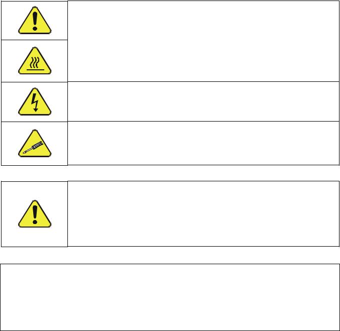
A safety message alerts you to potential hazards that could hurt you or others. Each safety message is associated with a safety alert symbol. These symbols are found in the manual and inside the instrument. The definition of these symbols is described below:
General Safety Hazard: Refer to the instructions for details on the specific hazard.
CAUTION: Hot Surface Hazard.
CAUTION: Electrical Shock Hazard.
TECHNICIAN SYMBOL: All operations marked with this symbol are to be performed by qualified maintenance personnel only.
CAUTION
General Safety Hazard
The M100E Analyzer should only be used for the purpose and in the manner described in this manual. If you use the M100E in a manner other than that for which it was intended, unpredictable behavior could ensue with possible hazardous consequences.
Technical Assistance regarding the use and maintenance of the M100E or any other Teledyne API product
can be obtained by contacting Teledyne API’s Customer Service Department by: Phone at 800-324-5190
Sending an email to api-customerservice@teledyne.com or
Accessing various service options on our website at http://www.teledyne-api.com/.
04515F DCN6048 |
15 |

Introduction |
Teledyne API M100E Analyzer Operation Manual |
1.2. M100E OVERVIEW
The Model 100E (also referred to as M100E) UV Fluorescence SO2 Analyzer is a microprocessor controlled analyzer that determines the concentration of sulfur dioxide (SO2), in a sample gas drawn through the instrument’s sample chamber where it is exposed to ultraviolet light causing any SO2 present to fluoresce. The instrument measures the amount of fluorescence to determine the amount of SO2 present in the sample gas.
The M100E’s exceptional stability is achieved with the use of an optical shutter to compensate for sensor drift and a reference detector to correct for changes in UV lamp intensity. Additionally, an advanced optical design combined with a special scrubber, called a "kicker" that removes hydrocarbons (which fluoresces similarly to SO2) prevents inaccuracies due to interferents.
Calibration of the instrument is performed in software that stores SO2 concentration measurements made when specific, known concentrations of SO2 are supplied to the analyzer. The microprocessor uses these calibration values along with other performance parameters such as the sensor offset, UV lamp intensity, the amount of stray light present, and measurements of the temperature and pressure of the sample gas to compute the final SO2 concentration.
Built-in data acquisition capability, using the analyzer's internal memory, allows the logging of multiple parameters including averaged or instantaneous concentration values, calibration data, and operating parameters such as pressure and flow rate. Stored data are easily retrieved through the serial port or optional Ethernet port via our APICOM software or from the front panel, allowing operators to perform predictive diagnostics and enhanced data analysis by tracking parameter trends. Multiple averaging periods of one minute to 365 days are available for over a period of one year.
Some of the features of your M100E UV Fluorescence Sulfur Dioxide Analyzer are:
Standard two year warranty
Ranges, 0-50 ppb to 0-20,000 ppb, user selectable
Dual ranges and auto ranging
Microprocessor controlled for versatility
Multi-tasking software to allow viewing test variables while operating
Continuous self checking with alarms
Dual bi-directional RS-232 ports for remote operation (optional RS-485 or Ethernet)
Digital status outputs indicate instrument operating condition
Adaptive signal filtering tp optimize response time
Temperature & Pressure compensation
Internal Zero & Span check (optional)
Internal data logging with 1 min to 365 day multiple averages
Critical flow orifices to provide flow stability
1.3. M100E DOCUMENTATION
The documentation (part number 04515) for this instrument is available in several different formats:
Printed format, or;
Electronic format on a CD-ROM.
The electronic manual is in Adobe® Systems Inc. “Portable Document Format”. The Adobe® Acrobat Reader® software, which is necessary to view these files, can be downloaded for free from the internet at http://www.adobe.com/.
16 |
04515F DCN6048 |

Teledyne API M100E Analyzer Operation Manual |
Introduction |
|
|
Additional documentation for the M100E SO2 Analyzer is available from Teledyne API’s website at http://www.teledyne-api.com/manuals/.
APICOM software manual, part number 03945.
Multidrop manual, part number 01842.
iDAS Manual, part number 02837.
1.3.1. USING THIS MANUAL
NOTE
Throughout this manual, words printed in capital, bold letters, such as SETUP or ENTR represent messages as they appear on the analyzer’s display.
This manual has the following structure:
TABLE OF CONTENTS
Outlines the contents of the manual in the order the information are presented. This is a good overview of the topics covered in the manual. There is also a list of appendices, figures and tables.
SECTION I – GENERAL INFORMATION
INTRODUCTION
A brief description of the M100E analyzer architecture as well as a description of the layout of the manual and what information is located in its various sections and chapters.
SPECIFICATIONS AND WARRANTY
A list of the analyzer’s performance specifications and if applicable a description of the conditions and configuration under which EPA equivalency was approved as well as the Teledyne API’s warranty statement.
GETTING STARTED
Instructions for setting up, installing and running your analyzer for the first time.
GLOSSARY
Answers to the most frequently asked questions about operating the analyzer and a glossary of acronyms and technical terms.
OPTIONAL HARDWARE & SOFTWARE
A description of optional equipment to add functionality to your analyzer.
04515F DCN6048 |
17 |

Introduction |
Teledyne API M100E Analyzer Operation Manual |
SECTION II – OPERATING INSTRUCTIONS
BASIC OPERATION OF THE M100E ANALYZER
Step-by-Step instructions for using the display/keyboard to set up and operate the M100E analyzer.
ADVANCED FEATURES OF THE M100E ANALYZER
Step-by-Step instructions for using the M100E analyzer’s more advanced features such as the iDAS system, the DIAG and VARS menus and the and the TEST channel analog output.
REMOTE OPERATION OF THE M100E Analyzer
Information and instructions for interacting with the M100E analyzer via its several remote interface options (e.g. via RS-232, Ethernet, its built in digital control inputs/outputs, etc.)
M100E VALIDATION AND VERIFICATION
Methods and procedures for verifying the correct operation of your M100E Analyzer as well as step by step instructions for calibrating it
EPA PROTOCOL CALIBRATION
Specific information regarding calibration requirements for analyzers used in EPA monitoring.
SECTION III – TECHNICAL INFORMATION
THEORY OF OPERATION
An in-depth look at the various principals by which your analyzer operates as well as a description of how the various electronic, mechanical and pneumatic components of the analyzer work and interact with each other. A close reading of this section is invaluable for understanding the analyzer’s operation.
MAINTENANCE SCHEDULE AND PROCEDURES
Description of preventative maintenance procedures that should be regularly performed on you analyzer to assure good operating condition.
GENERAL TROUBLESHOOTING & REPAIR OF THE M100E ANALYZER
This section includes pointers and instructions for diagnosing problems with the analyzer in general and the Terminus as well as instructions on performing repairs of on the Terminus.
A PRIMER ON ELECTRO-STATIC DISCHARGE
This section describes how static electricity occurs; why it is a significant concern and; how to avoid it and avoid allowing ESD to affect the reliable and accurate operation of your analyzer.
APPENDICES
For easier access and better updating, some information has been separated out of the manual and placed in a series of appendices at the end of this manual. These include version-specific software menu trees, warning messages, definitions Modbus registers and serial I/O variables as well as spare part listings, repair questionnaires, interconnect drawing, detailed pneumatic and electronic schematics.
NOTE
The flowcharts in this manual contain typical representations of the analyzer’s display during the various operations being described. These representations are not intended to be exact and may differ slightly from the actual display of your instrument.
18 |
04515F DCN6048 |
2. SPECIFICATIONS, APPROVALS AND WARRANTY
2.1. SPECIFICATIONS
|
Table 2-1: M100E Basic Unit Specifications |
|
|
|
|
Min/Max Range |
|
In 1ppb increments from 50 ppb to 20,000 ppb of Full Scale, dual ranges or auto ranging |
(Physical Analog Output) |
|
|
Measurement Units |
|
ppb, ppm, µg/m3, mg/m3 (user selectable) |
Zero Noise1 |
|
≤ 0.2 ppb RMS |
Span Noise1 |
|
≤ 0.5% of reading, above 50 ppb |
Lower Detectable Limit2 |
|
0.4 ppb |
Zero Drift (24 hours) |
|
≤ 0.5 ppb |
Zero Drift (7 days) |
|
≤ 1 ppb |
Span Drift (24 hours) |
|
≤ 0.5% of Full Scale |
Span Drift (7 days) |
|
≤ 1% of Full Scale |
Linearity |
|
≤ 1% of Full Scale |
Precision |
|
≤ 0.5% of reading1 above 50 ppb |
Lag Time1 |
|
20 seconds |
Rise/Fall Time1 |
|
95% in <100 sec |
Sample Flow Rate |
|
650 cm3/min. ±10% |
Temperature Range |
|
5-40 oC |
Humidity Range |
|
0 - 95% RH, non-condensing |
Dimensions H x W x D |
|
7" x 17" x 23.5" (178 mm x 432 mm x 597 mm) |
Weight, Analyzer |
|
41.45 lbs (18.80 kg) with internal pump |
(Basic Configuration) |
|
36.45 lbs (16.53 kg) without internal pump |
AC Power Rating |
|
100 V, 50/60 Hz, 2.50 A |
|
|
115 V, 50/60 Hz, 2.08 A |
|
|
220 V, 50/60 Hz, 1.14 A |
|
|
240 V, 50/60 Hz, 1.04 A |
Environmental |
|
Installation category (over-voltage category) II; Pollution degree 2 |
Recorder Offset |
|
± 10 % |
Analog Outputs (Optional |
|
Select up to 3 channels |
4-20 mA) |
|
|
Analog Output Ranges |
|
10 V, 5 V, 1 V, 0.1 V selectable |
Analog Output Resolution |
|
1 part in 4096 of selected full-scale voltage |
Status Outputs |
|
8 Status outputs from opto-isolators |
|
|
|
Control Inputs |
|
6 Control Inputs, 3 defined, 3 spare |
Serial I/O |
|
One (1) RS-232; One (1) RS-485 (2 connecters in parallel) |
|
|
Baud Rate : 300 – 115200: Optional Ethernet Interface |
Certifications |
|
EN61326 (1997 w/A1: 98) Class A, FCC Part 15 Subpart B Section 15.107 Class A, |
|
|
ICES-003 Class A (ANSI C63.4 1992) & AS/NZS 3548 (w/A1 & A2; 97) Class A. |
|
|
IEC 61010-1:90 + A1:92 + A2:95, |
Approvals |
|
USEPA EQSA-0495-100 |
|
|
MCERTS certified SIRA MC050067/00 |
|
|
EN14212, Approved, CE and Others. |
1 As defined by the USEPA.
2 Defined as twice the zero noise level by the USEPA.
04515F DCN6048 |
19 |

Specifications, Approvals and Warranty |
Teledyne API M100E Analyzer Operation Manual |
2.2. EPA EQUIVALENCY DESIGNATION
The M100E Analyzer is designated as Reference Method Number EQSA-0495-100 as per 40 CFR Part 53 when operated under the following conditions:
Range: Any range from 50 parts per billion (ppb) to 10 parts per million (ppm).
Ambient temperature range of 5 oC to 40 oC.
Line voltage range of 100-120 VAC or 220-240 VAC, at 50 or 60 Hz.
Sample filter: Equipped with PTFE filter element in the internal filter assembly.
Sample flow of 650 +/- 65 cm3/min.
Vacuum pump (internal) capable of 14"Hg Absolute pressure @ 1 slpm or better.
Software settings:
Dynamic span |
OFF |
|
|
Dynamic zero |
OFF |
|
|
Dilution factor |
OFF |
AutoCal |
ON or OFF |
Dual range |
ON or OFF |
Auto-range |
ON or OFF |
|
|
Temp/Pressure compensation |
ON |
|
|
Under the designation, the analyzer may be operated with or without the following optional equipment:
Rack mount with chassis slides.
Rack mount without slides, ears only.
Zero/span valve options.
Internal zero/span (IZS) option with either:
SO2 permeation tube - 0.4ppm at 0.7 liter per minute; certified/uncertified.
SO2 permeation tube - 0.8 ppm at 0.7 liter per minute; certified/uncertified. Under the designation, the IZS option cannot be used as the source of calibration.
4-20mA isolated analog outputs.
Status outputs.
Control inputs.
RS-232 output.
Ethernet output.
Zero air scrubber.
4-20mA, isolated output.
20 |
04515F DCN6048 |

Teledyne API M100E Analyzer Operation Manual |
Specifications, Approvals and Warranty |
|
|
2.3.CE MARK COMPLIANCE
2.3.1.EMISSIONS COMPLIANCE
The Teledyne-Advanced Pollution Instrumentation UV Fluorescence SO2 Analyzer M100E was tested and found to be fully compliant with:
EN61326 (1997 w/A1: 98) Class A, FCC Part 15 Subpart B Section 15.107 Class A, ICES-003 Class A (ANSI C63.4 1992) & AS/NZS 3548 (w/A1 & A2; 97) Class A.
Tested on 21 February 2003 - 08 March 2003 at CKC Laboratories, Inc., Report Number CE03-021A.
2.3.2. SAFETY COMPLIANCE
The Teledyne-Advanced Pollution Instrumentation UV Fluorescence SO2 Analyzer M100E was tested and found to be fully compliant with:
IEC 61010-1:90 + A1:92 + A2:95,
Issued by CKC Laboratories on 4 April 2003, Report Number WO-80146.
2.4. WARRANTY
WARRANTY POLICY (02024D)
Prior to shipment, Teledyne API equipment is thoroughly inspected and tested. Should equipment failure occur, Teledyne API assures its customers that prompt service and support will be available.
COVERAGE
After the warranty period and throughout the equipment lifetime, Teledyne API stands ready to provide on-site or in-plant service at reasonable rates similar to those of other manufacturers in the industry. All maintenance and the first level of field troubleshooting are to be performed by the customer.
NON-API MANUFACTURED EQUIPMENT
Equipment provided but not manufactured by Teledyne API is warranted and will be repaired to the extent and according to the current terms and conditions of the respective equipment manufacturer’s warranty.
GENERAL
During the warranty period, Teledyne API warrants each Product manufactured by Teledyne API to be free from defects in material and workmanship under normal use and service. Expendable parts are excluded.
If a Product fails to conform to its specifications within the warranty period, Teledyne API shall correct such defect by, at Teledyne API's discretion, repairing or replacing such defective Product or refunding the purchase price of such Product.
The warranties set forth in this section shall be of no force or effect with respect to any Product: (i) that has been altered or subjected to misuse, negligence or accident, or (ii) that has been used in any manner other than in accordance with the instruction provided by Teledyne API, or (iii) not properly maintained.
04515F DCN6048 |
21 |

Specifications, Approvals and Warranty |
Teledyne API M100E Analyzer Operation Manual |
THE WARRANTIES SET FORTH IN THIS SECTION AND THE REMEDIES THEREFORE ARE EXCLUSIVE AND IN LIEU OF ANY IMPLIED WARRANTIES OF MERCHANTABILITY, FITNESS FOR PARTICULAR PURPOSE OR OTHER WARRANTY OF QUALITY, WHETHER EXPRESSED OR IMPLIED. THE REMEDIES SET FORTH IN THIS SECTION ARE THE EXCLUSIVE REMEDIES FOR BREACH OF ANY WARRANTY CONTAINED HEREIN. API SHALL NOT BE LIABLE FOR ANY INCIDENTAL OR CONSEQUENTIAL DAMAGES ARISING OUT OF OR RELATED TO THIS AGREEMENT OF Teledyne API'S PERFORMANCE HEREUNDER, WHETHER FOR BREACH OF WARRANTY OR OTHERWISE
TERMS AND CONDITIONS
All units or components returned to Teledyne API should be properly packed for handling and returned freight prepaid to the nearest designated Service Center. After the repair, the equipment will be returned, freight prepaid.
22 |
04515F DCN6048 |
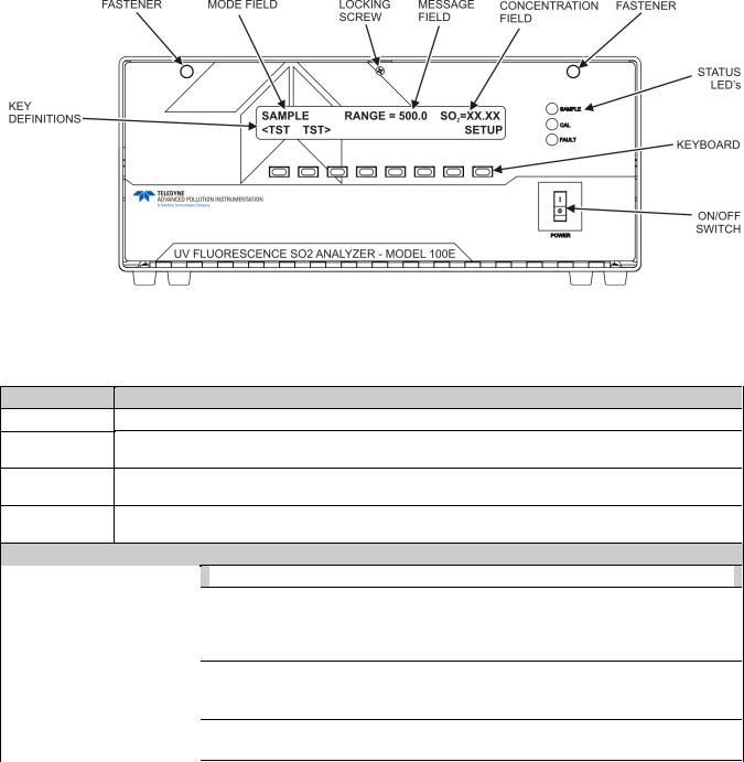
3. GETTING STARTED
3.1. M100E ANALYZER LAYOUT
Figure 3-1: Front Panel Layout
Table 3-1: Front Panel Description
Field
Mode
Message
Concentration
Keypad
Definition
STATUS LED’s
Significance
Displays the name of the analyzer’s current operating mode
Displays a variety of informational messages such as warning messages, operational data, test function values and response messages during interactive tasks.
Displays the actual concentration of the sample gas currently being measured by the analyzer in the currently selected units of measure
Displays dynamic, context sensitive definitions for the row of keys just below the display.
|
Name |
Color |
|
State |
|
Definition |
|
|
|
|
Off |
|
Unit is not operating in sample mode, iDAS is disabled. |
|
SAMPLE |
Green |
|
On |
|
Sample Mode active; Front Panel Display being updated; iDAS data being stored. |
|
|
Blinking |
|
Unit is operating in sample mode, front panel display being updated, iDAS hold-off mode |
||
|
|
|
|
|
||
|
|
|
|
|
|
is ON, iDAS disabled |
|
|
|
|
Off |
|
Auto Cal disabled |
|
CAL |
Yellow |
|
On |
|
Auto Cal enabled |
|
|
|
|
Blinking |
|
Unit is in calibration mode |
|
FAULT |
Red |
|
Off |
|
No warnings exist |
|
|
Blinking |
|
Warnings exist |
||
|
|
|
|
|
||
|
|
|
|
|
|
|
04515F DCN6048 |
23 |

Getting Started |
Teledyne API M100E Analyzer Operation Manual |
Figure 3-2: Rear Panel Layout
|
Table 3-2: Inlet / Outlet Connector Description |
|
|
rear panel Label |
Function |
|
|
SAMPLE |
Connect a gas line from the source of sample gas here. |
Calibration gasses are also inlet here on units without zero/span/shutoff valve options |
|
|
installed. |
EXHAUST |
Connect an exhaust gas line of not more than 10 meters long here that leads outside |
the shelter or immediate area surrounding the instrument. |
|
SPAN |
On units with zero/span/shutoff valve options installed, connect a gas line to the source |
of calibrated span gas here. |
|
ZERO AIR |
Internal Zero Air: On units with zero/span/shutoff valve options installed but no internal |
zero air scrubber attach a gas line to the source of zero air here. |
24 |
04515F DCN6048 |

Teledyne API M100E Analyzer Operation Manual |
Getting Started |
||
|
|
|
|
|
|
|
|
|
|
|
|
Figure 3-3: M100E Layout (Basic Unit – No Valve Options)
04515F DCN6048 |
25 |
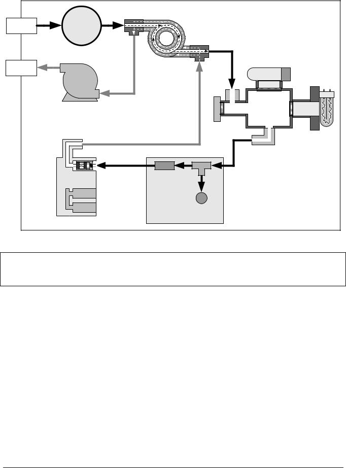
Getting Started |
Teledyne API M100E Analyzer Operation Manual |
(Kicker) |
Figure 3-4: M100E Internal Gas Flow (Basic Configuration)
NOTE
For pneumatic diagrams of M100E SO2 Analyzer’s with various calibration valve options refer to Section 5.7.
26 |
04515F DCN6048 |
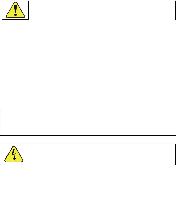
Teledyne API M100E Analyzer Operation Manual |
Getting Started |
|
|
3.2. UNPACKING THE M100E ANALYZER
CAUTION
GENERAL SAFETY HAZARD
To avoid personal injury, always use two persons to lift and carry the M100E.
1.Verify that there is no apparent external shipping damage. If damage has occurred, please advise the shipper first, then Teledyne API.
2.Included with your analyzer is a printed record of the final performance characterization performed on your instrument at the factory. It is titled Final Test and Validation Data Sheet (P/N 04551). This record is an important quality assurance and calibration record for this instrument. It should be placed in the quality records file for this instrument.
3.Carefully remove the top cover of the analyzer and check for internal shipping damage by:
Removing the locking screw located in the top, center of the Front panel;
Removing the two flat head, Phillips screws on the sides of the instrument;
Sliding the cover backwards until it clears the analyzer’s front bezel, and;
Lifting the cover straight up.
4.Inspect the interior of the instrument to ensure that all circuit boards and other components are in good shape and properly seated.
5.Check the connectors of the various internal wiring harnesses and pneumatic hoses to ensure that they are firmly and properly seated.
6.Verify that all of the optional hardware ordered with the unit has been installed. These are listed on the paperwork accompanying the analyzer.
NOTE
Printed Circuit Assemblies (PCAs) are sensitive to electro-static discharges too small to be felt by the human nervous system. Failure to use ESD protection when working with electronic assemblies will void the instrument warranty.
Refer to Chapter 13 for more information on preventing ESD damage.
CAUTION
ELECTRICAL SHOCK HAZARD
Never disconnect PCAs, wiring harnesses or electronic subassemblies while under power.
04515F DCN6048 |
27 |
Getting Started |
Teledyne API M100E Analyzer Operation Manual |
3.2.1. VENTILATION CLEARANCE
Whether the analyzer is set up on a bench or installed into an instrument rack, be sure to leave sufficient ventilation clearance.
Table 3-3: Ventilation Clearance
AREA |
MINIMUM REQUIRED |
|
CLEARANCE |
||
|
||
Back of the instrument |
4 in. |
|
Sides of the instrument |
1 in. |
|
Above and below the |
1 in. |
|
instrument |
||
|
Various rack mount kits are available for this analyzer. Refer to Section 5.2 of this manual for more information.
3.3.ELECTRICAL CONNECTIONS
3.3.1.POWER CONNECTION
Attach the power cord to the analyzer and plug it into a power outlet capable of carrying at least 10 Amps of current at your AC voltage and that it is equipped with a functioning earth ground.
CAUTION
ELECTRICAL SHOCK HAZARD
High Voltages are present inside the analyzers case. Power connection must have functioning ground connection.
Do not defeat the ground wire on power plug.
Turn off analyzer power before disconnecting or connecting electrical subassemblies.
Do not operate instrument with the cover off.
CAUTION
GENERAL SAFETY HAZARD
The M100E analyzer can be configured for both 100-120 V and 220-240 V at either 50 or 60 Hz.
To avoid damage to your analyzer, ensure that the AC power voltage matches the voltage indicated on the Analyzer’s serial number label tag (refer to Figure 3-2) before plugging the M100E into line power.
28 |
04515F DCN6048 |
Loading...