


OPERATING INSTRUCTIONS
Model 3010MA
Paramagnetic Oxygen Purity
Analyzer
P/N M3010MA 7/01/10
DANGER
Toxic gases and or flammable liquids may be present in this monitoring system. Personal protective equipment may be required when servicing this instrument.
Hazardous voltages exist on certain components internally which may persist for a time even after the power is turned off and disconnected.
Only authorized personnel should conduct maintenance and/or servicing. Before conducting any maintenance or servicing, consult with authorized supervisor/manager.
Teledyne Analytical Instruments |
i |

Model 3010MA
Copyright © 2010 TELEDYNE Analytical Instruments
All Rights Reserved. No part of this manual may be reproduced, transmitted, transcribed, stored in a retrieval system, or translated into any other language or computer language in whole or in part, in any form or by any means, whether it be electronic, mechanical, magnetic, optical, manual, or otherwise, without the prior written consent of Teledyne Analytical Instruments, 16830 Chestnut Street, City of Industry, CA 91749-1580.
Warranty
This equipment is sold subject to the mutual agreement that it is warranted by us free from defects of material and of construction, and that our liability shall be limited to replacing or repairing at our factory (without charge, except for transportation), or at customer plant at our option, any material or construction in which defects become apparent within one year from the date of shipment, except in cases where quotations or acknowledgments provide for a shorter period. Components manufactured by others bear the warranty of their manufacturer. This warranty does not cover defects caused by wear, accident, misuse, neglect or repairs other than those performed by Teledyne or an authorized service center. We assume no liability for direct or indirect damages of any kind and the purchaser by the acceptance of the equipment will assume all liability for any damage which may result from its use or misuse.
We reserve the right to employ any suitable material in the manufacture of our apparatus, and to make any alterations in the dimensions, shape or weight of any parts, in so far as such alterations do not adversely affect our warranty.
Important Notice
This instrument provides measurement readings to its user, and serves as a tool by which valuable data can be gathered. The information provided by the instrument may assist the user in eliminating potential hazards caused by his process; however, it is essential that all personnel involved in the use of the instrument or its interface, with the process being measured, be properly trained in the process itself, as well as all instrumentation related to it.
The safety of personnel is ultimately the responsibility of those who control process conditions. While this instrument may be able to provide early warning of imminent danger, it has no control over process conditions, and it can be misused. In particular, any alarm or control systems installed must be tested and understood, both as to how they operate and as to how they can be defeated. Any safeguards required such as locks, labels, or redundancy, must be provided by the user or specifically requested of Teledyne at the time the order is placed.
Therefore, the purchaser must be aware of the hazardous process conditions. The purchaser is responsible for the training of personnel, for providing hazard warning methods and instrumentation per the appropriate standards, and for ensuring that hazard warning devices and instrumentation are maintained and operated properly.
Teledyne Analytical Instruments (TAI) cannot accept responsibility for conditions beyond its knowledge and control. No statement expressed or implied by this document or any information disseminated by the manufacturer or its agents, is to be construed as a warranty of adequate safety control under the user’s process conditions.
ii |
Teledyne Analytical Instruments |
Paramagnetic O2 Purity Analyzer
Safety Messages
Your safety and the safety of others is very important. We have provided many important safety messages in this manual. Please read these messages carefully.
A safety message alerts you to potential hazards that could hurt you or others. Each safety message is associated with a safety alert symbol. These symbols are found in the manual and inside the instrument. The definition of these symbols is described below:
GENERAL WARNING/CAUTION: Refer to the instructions for details on the specific danger. These cautions warn of specific procedures which if not followed could cause bodily Injury and/or damage the instrument.
CAUTION: HOT SURFACE WARNING: This warning is specific to heated components within the instrument. Failure to heed the warning could result in serious burns to skin and underlying tissue.
WARNING: ELECTRICAL SHOCK HAZARD: Dangerous voltages
appear within this instrument. This warning is specific to an electrical hazard existing at or nearby the component or procedure under discussion. Failure to heed this warning could result in injury and/or death from electrocution.
Technician Symbol: All operations marked with this symbol are to be performed by qualified maintenance personnel only.
NOTE: Additional information and comments regarding a specific component or procedure are highlighted in the form of a note.
CAUTION: THE ANALYZER SHOULD ONLY BE USED FOR THE PURPOSE AND IN THE MANNER DESCRIBED IN THIS MANUAL.
IF YOU USE THE ANALYZER IN A MANNER OTHER THAN THAT FOR WHICH IT WAS INTENDED, UNPREDICTABLE BEHAVIOR COULD RESULT
Teledyne Analytical Instruments |
iii |

Model 3010MA
POSSIBLY ACCOMPANIED WITH HAZARDOUS
CONSEQUENCES.
This manual provides information designed to guide you through the installation, calibration and operation of your new analyzer. Please read this manual and keep it available.
Occasionally, some instruments are customized for a particular application or features and/or options added per customer requests. Please check the front of this manual for any additional information in the form of an Addendum which discusses specific information, procedures, cautions and warnings that may be peculiar to your instrument.
Manuals do get lost. Additional manuals can be obtained from Teledyne at the address given in the Appendix. Some of our manuals are available in electronic form via the internet. Please visit our website at: www.teledyne-ai.com.
iv |
Teledyne Analytical Instruments |

Paramagnetic O2 Purity Analyzer
Table of Contents
Safety Messages........................................................................... |
iii |
||
Tables .......................................................................................... |
|
viii |
|
Figures .......................................................................................... |
|
ix |
|
Preface ......................................................................................... |
|
11 |
|
Overview |
|
11 |
|
Introduction ................................................................................. |
|
15 |
|
1.1 |
Overview |
|
15 |
1.2 |
Front Panel (Operator Interface) |
15 |
|
1.3 |
Rear Panel (Equipment Interface) |
17 |
|
Operational Theory...................................................................... |
19 |
||
2.1 |
Introduction |
|
19 |
2.2 |
Electronics and Signal Processing |
21 |
|
2.5 |
Temperature Control |
22 |
|
Installation ................................................................................... |
|
25 |
|
3.1 |
Unpacking the Analyzer |
25 |
|
3.2 |
Mounting the Analyzer |
25 |
|
3.3 |
Rear Panel Connections—Control Unit |
28 |
|
|
3.3.1 Gas Connections—Control Unit |
28 |
|
|
3.3.2 Electrical Connections—Control Unit |
29 |
|
|
3.3.2.1 |
Primary Input Power |
29 |
|
3.3.2.2 |
Fuse Installation |
29 |
|
3.3.2.3 |
50-Pin D-Equipment Interface Connector |
29 |
|
3.3.2.4 |
RS-232 Port |
36 |
3.4 |
Installing the Analysis Unit |
37 |
|
3.5 |
Rear Panel Connections—Analysis Unit |
38 |
|
|
3.5.1 Gas Connections—Analysis Unit |
39 |
|
3.6 |
Testing the System |
39 |
|
Operation ..................................................................................... |
|
41 |
|
Teledyne Analytical Instruments |
v |

Model 3010MA
4.1 |
Introduction |
|
41 |
|
4.2 |
Using the Data Entry and Function Buttons |
41 |
||
4.3 |
The System Function |
43 |
||
|
4.3.1 |
Setting the Display |
44 |
|
|
4.3.2 |
Setting up an Auto-Cal |
44 |
|
|
4.3.3 |
Password Protection |
45 |
|
|
4.3.3.1 |
Entering the Password |
46 |
|
|
4.3.3.2 |
Installing or Changing the Password |
47 |
|
|
4.3.4 |
Logout |
48 |
|
|
4.3.5 |
System Self-Diagnostic Test |
49 |
|
|
4.3.6 |
Version Screen |
50 |
|
|
4.3.7 Display Sensor Output |
50 |
||
4.4 |
The Zero and Span Functions |
50 |
||
|
4.4.1 Span Cal |
51 |
||
|
4.4.1.1 Auto Mode Spanning |
51 |
||
|
4.4.1.2 Manual Mode Spanning |
52 |
||
4.5 |
The Alarms Function |
53 |
||
4.6 |
The Range Function |
55 |
||
|
4.6.1 |
Setting the Analog Output Ranges |
56 |
|
|
4.6.2 |
Autoranging Analysis |
56 |
|
|
4.6.3 |
Fixed Range Analysis |
56 |
|
4.7 |
The Analyze Function |
57 |
||
4.8 |
Signal Output |
57 |
||
Maintenance................................................................................. |
|
59 |
||
5.1 |
Routine Maintenance |
59 |
||
5.2 |
Fuse Replacement |
59 |
||
5.3 |
System Self Diagnostic Test |
60 |
||
5.4 |
Major Internal Components |
61 |
||
5.5 |
Cleaning |
|
63 |
|
Analysis Unit................................................................................ |
|
67 |
||
6.1 |
Overview |
|
67 |
|
6.2 |
Paramagnetic Sensor |
68 |
||
|
6.2.1 |
Principles of Operation |
68 |
|
vi |
Teledyne Analytical Instruments |

Paramagnetic O2 Purity Analyzer
|
6.2.2 Cross Interference |
71 |
6.3 |
Oven and Temperature Controller |
74 |
6.4 |
Sample System |
75 |
6.5 |
Leak Checking the Analysis Unit |
78 |
6.6 |
Initial Sensor Calibration |
78 |
Appendix ...................................................................................... |
81 |
|
A-1 Model 3010MA Specifications |
81 |
|
A-2 Recommended 2-Year Spare Parts List |
83 |
|
A-3 |
Drawing List |
84 |
A.4 Programmable Pressure Compensation Adjustment |
85 |
|
Teledyne Analytical Instruments |
vii |

Model 3010MA
Tables |
|
Table 3-1: Analog Output Connections.......................................... |
30 |
Table 3-2: Alarm Relay Contact Pins............................................. |
31 |
Table 3-3: Remote Calibration Connections.................................. |
32 |
Table 3-4: Range ID Relay Connections ....................................... |
33 |
Table 3-5: 50-Pin Equipment Interface Connector ........................ |
35 |
Table 3-6: Commands via RS-232 Input ....................................... |
37 |
Table 3-7: Required RS-232 Options ............................................ |
37 |
Table 4.1:Linear Analog Output..................................................... |
57 |
Table 4-2: Range ID Output .......................................................... |
58 |
Table 5-1: Self-Test Failure Codes................................................ |
60 |
Table 6-1: Sensor Cable Pin Configuration ................................... |
70 |
Table 6-2: Cross Sensitivity of Various Gases .............................. |
73 |
Table 6-3: Pressure Ranges of Available Restrictors .................... |
75 |
viii |
Teledyne Analytical Instruments |

Paramagnetic O2 Purity Analyzer
Figures |
|
Figure 1-1: Model 3010MA Control Unit Front Panel..................... |
16 |
Figure 1-2 Rear Panel of Model 3010MA Control Unit .................. |
18 |
Figure 2-1: Block Diagram for Model 3010MA Control Unit........... |
20 |
Figure 2-2: Block Diagram for Model 3010MA Analysis Unit ......... |
20 |
Figure 2-3: Location of Electronic Components in Control Unit ..... |
21 |
Figure 2-4: Block Diagram of the Model 3010MA Electronics ....... |
23 |
Figure 3-1: Rack Mountable Control and Analysis Units ............... |
26 |
Figure 3-2: Front Panel of the Model 3010MA.............................. |
27 |
Figure 3-3: Required Front Door Clearance .................................. |
27 |
Figure 3-4: Rear Panel of the Model 3010MA Control Unit ........... |
28 |
Figure 3-5: Equipment Interface Connector Pin Arrangement....... |
30 |
Figure 3-6: Remote Valve Connections......................................... |
34 |
Figure 3-7: FET Series Resistance................................................ |
35 |
Figure 3-8: Analysis Unit Rear Panel............................................. |
38 |
Figure 4-1: Hierarchy of Functions Available on the Model 3010MA42 |
|
Figure 5-1: Removing Fuse Block from Housing ........................... |
59 |
Figure 5-2: Installing Fuses ........................................................... |
60 |
Figure 5-3: Internal Components of the Control Unit ..................... |
61 |
Figure 5-4: Rear-Panel Screws ..................................................... |
63 |
Figure 6-1: Side view of Paramagnetic Sensor ............................. |
69 |
Figure 6-2: Front View of the Paramagnetic Sensor...................... |
69 |
Figure 6-3: Sensor and Trimpot Identification................................ |
70 |
Figure 6-4: 15-Pin Sensor Cable and Pin Identification................. |
72 |
Figure 6-5: Access to Temperature Controller in Control Unit ....... |
74 |
Figure 6-6: Piping Diagram for Model 3010MA ............................. |
77 |
Figure 6-7: Analysis Unit Front Panel............................................ |
77 |
Teledyne Analytical Instruments |
ix |

Model 3010MA
x |
Teledyne Analytical Instruments |
Paramagnetic O2 Purity Analyzer |
Introduction |
|
|
|
|
Preface
Overview
The Teledyne Analytical Instruments Model 3010MA Paramagnetic Oxygen Purity Analyzer is a versatile microprocessor-based instrument for analyzing the purity of an oxygen bearing gas stream. It is a “split architecture” instrument designed for indoor use in non-hazardous areas. The Control Unit contains the operator interface, electronics and display. The Analysis Unit is a separate insulated and temperature controlled enclosure which contains the oven, sensor, sample system and flowmeter. The analyzer has three user settable ranges that encompass the complete range of 0-100% oxygen. The ranges can be set to any convenient level between 0 and 100% in one percent increments.
Note: The upper value of every range is non-adjustable and is fixed at 100% . The lower value can be adjusted anywhere from 99% to 0%.
Part I of this manual covers the Model 3010MA flush-panel and/or rack-mount Control Unit. The Analysis Unit is covered in Part II of this manual.
Typical Applications
A few typical applications of the Model 3010MA are:
•Monitoring inert gas blanketing
•Air separation and liquefaction
•Chemical reaction monitoring
•Semiconductor manufacturing
•Petrochemical process control
•Quality assurance
•Gas analysis certification.
Teledyne Analytical Instruments |
11 |

Part 1 Control Unit |
Model 3010MA |
|
|
|
|
Main Features of the Analyzer
The Model 3010MA series Paramagnetic Oxygen Analyzers are sophisticated yet simple to use. The main features of these analyzers include:
•A 2-line alphanumeric display screen, driven by microprocessor electronics, that continuously prompts and informs the operator.
•High resolution, accurate readings of oxygen content
•Paramagnetic oxygen sensor
•Microprocessor based electronics: 8-bit CMOS microprocessor with 32 kB RAM and 128 kB ROM.
•Three user settable analysis ranges allow best match to users process and equipment. Default setting are: 0-100%, 95-100%, and 98-100% oxygen.
•Auto Ranging allows analyzer to automatically select the proper preset range within the 0-100% range of the sensor. Manual override allows the user to lock onto a specific range of interest.
•Two user-adjustable concentration alarms and a system failure alarm.
•Self-diagnostic testing, at startup and on demand, with continuous power-supply monitoring.
•Two way RFI protection.
•RS-232 serial digital port for use with a computer or other digital communications device.
•Analog outputs for Concentration and Analysis Range: 0–1VDC standard. Isolated 4–20 mA dc standard.
•Compact and versatile design—flush-panel, or rack-mountable
12 |
Teledyne Analytical Instruments |
Paramagnetic O2 Purity Analyzer |
Introduction |
|
|
|
|
OPERATING INSTRUCTIONS
Model 3010MA
Paramagnetic Oxygen Purity
Analyzer
Part I: Control Unit
Teledyne Analytical Instruments |
13 |

Part 1 Control Unit |
Model 3010MA |
|
|
|
|
14 |
Teledyne Analytical Instruments |

Paramagnetic O2 Purity Analyzer |
Introduction |
|
|
|
|
Introduction
1.1 Overview
The Teledyne Analytical Instruments Model 3010MA Paramagnetic Oxygen Purity Analyzer is a versatile microprocessor-based instrument for detecting the percentage of oxygen in a gas stream. This part of the manual covers the Model 3010MA flush-panel and/or rack-mount Control Unit. These units are for indoor use in a nonhazardous environment.
In addition to supplying the interface for operating and controlling the analyzer, the Control Unit also houses:
Main circuit board
PID temperature controller
Pressure compensation circuitry
24VDC power supply for driving the Analysis Unit
Digital meter readout and display circuit board
Interface screen and circuit board
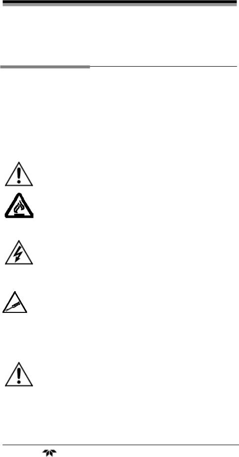
1.2Front Panel (Operator Interface)
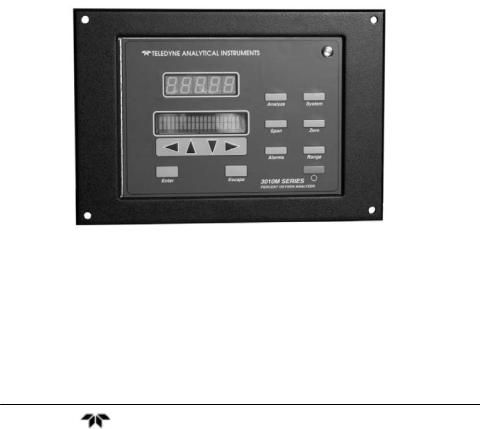
The standard 3010MA is housed in a rugged metal case with all controls and displays accessible from the front panel. See Figure 1-1. The front panel has thirteen buttons for operating the analyzer, a digital meter, and an alphanumeric display.
Function Keys:
Six touch-sensitive membrane switches are used to change the specific function performed by the analyzer:
•Analyze—Perform analysis for oxygen content of a sample gas.
•System—Perform system-related tasks (described in detail in chapter 4, Operation.).
•Span—Span calibrate the analyzer.
•Zero—Zero calibrate the analyzer.
Teledyne Analytical Instruments |
15 |
Part 1 Control Unit |
Model 3010MA |
|
|
|
|
•Alarms—Set the alarm setpoints and attributes.
•Range— Set up the 3 user definable ranges for the instrument.
Data Entry Keys:
Six touch-sensitive membrane switches are used to input data to the instrument via the alphanumeric VFD display:
•Left & Right Arrows—Select between functions currently displayed on the VFD screen.
•Up & Down Arrows—Increment or decrement values of functions currently displayed.
•Enter—Moves VFD display on to the next screen in a series. If none remains, returns to the Analyze screen.
•Escape—Moves VFD display back to the previous screen in a series. If none remains, returns to the Analyze screen.
Digital Meter Display:
The meter display is a LED device that produces large, bright, 7- segment numbers that are legible in any lighting environment. It produces a continuous readout of oxygen concentration. It is accurate across all ranges without the discontinuity inherent in analog range switching.
Alphanumeric Interface Screen:
The VFD screen is an easy-to-use interface from operator to analyzer. It displays values, options, and messages that give the operator immediate feedback.
Figure 1-1: Model 3010MA Control Unit Front Panel
16 |
Teledyne Analytical Instruments |

Paramagnetic O2 Purity Analyzer |
Introduction |
|
|
|
|
Standby Button:
The Standby feature turns off the display and outputs, but circuitry is still operating. It is useful for power saving as well as prolonging the life of the display elements.
WARNING: THE INSTRUMENT IS STILL ENERGIZED WHEN THE STANDBY BUTTON IS PRESSED.
THE POWER CABLE MUST BE UNPLUGGED TO DISCONNECT POWER FROM THE INSTRUMENT. WHEN CHASSIS IS EXPOSED OR WHEN ACCESS DOOR IS OPEN AND POWER CABLE IS CONNECTED, USE EXTRA CARE TO AVOID CONTACT WITH LIVE ELECTRICAL CIRCUITS.
Access Door:
To provide access to the display circuitry, the PID temperature controller or pressure compensation circuitry, the front panel swings open when the latch in the upper right corner of the panel is pressed all the way in with a narrow gauge tool. Accessing the main circuit board requires unfastening the rear panel screws and sliding the unit out of the case.
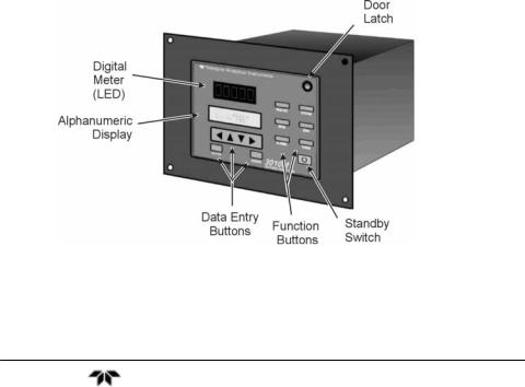
1.3 Rear Panel (Equipment Interface)
The rear panel of the Model 3010MA Control Unit is shown in Figure 1-2. Connections are made at this panel for power, RS-232 communication, equipment interfacing and connections to the Analysis Unit. The connectors are described briefly here and in detail in the Installation chapter of this manual.
•Power Connection— AC power source.
•Pressure In—1/8” Gas line input to pressure compensation circuit from Analysis Unit.
Line voltage—Selector switch for line voltage 115/230.
•RS-232 Port—Serial digital concentration signal output and control input.
•Sensor In Connector—15 pin D-connector sensor cable from Analysis Unit, (includes 24VDC power)
•Heater Out— 7 pin CPC connector, Power to heater in Analysis Unit
Teledyne Analytical Instruments |
17 |
Part 1 Control Unit |
Model 3010MA |
|
|
|
|
•Network—For future expansion. Not implemented at this printing.
50-Pin Equipment Interface Connector—provides access for:
Alarms—2 concentration and 1 system alarm
Analog Outputs—0-1VDC concentration and 0-1VDC range ID. 4-20 mA concentration and optional 4-20 mA range ID.
Remote Span/Zero—Digital inputs for external control of analyzer calibration
Calibration Contact—Special contacts to signal that the instrument is being calibrated and not monitoring sample
Range ID Contacts—Separate, dedicated range relay contacts for low medium and high ranges
Figure 1-2 Rear Panel of Model 3010MA Control Unit
18 |
Teledyne Analytical Instruments |

Paramagnetic O2 Purity Analyzer |
Operational Theory |
|
|
|
|
Operational Theory
2.1 Introduction
The analyzer is composed of three subsystems:
1.Paramagnetic Sensor
2.Sample System
3.Electronic Signal Processing, Display and Control
The paramagnetic sensor and the sample system are located in the Analysis Unit while the Electronic Signal Processing, Display and Control systems are housed in the Control Unit.
The sample system is designed to accept the sample gas and transport it through the analyzer without contaminating or altering the sample prior to analysis. It is described in detail in Part II Section 6.4 of this manual.
The Analysis Unit is separate from the Control Unit in order to provide critical temperature stability. The paramagnetic sensor is an electromechanical device that translates the amount of oxygen present in the sample into an electrical signal. It is a partial pressure device sensitive to both operating pressure (vent pressure) and temperature fluctuations. The output from the sensor is compensated for pressure variation using a baseline pressure initially set during calibration. Temperature at the sensor is held constant using an 80 Watt heater controlled by a PID temperature controller located in the Control Unit. Feedback from the sensor to the PID controller is supplied by an RTD installed in the Analysis Unit. The paramagnetic sensor is described in Part II Section 6.2.
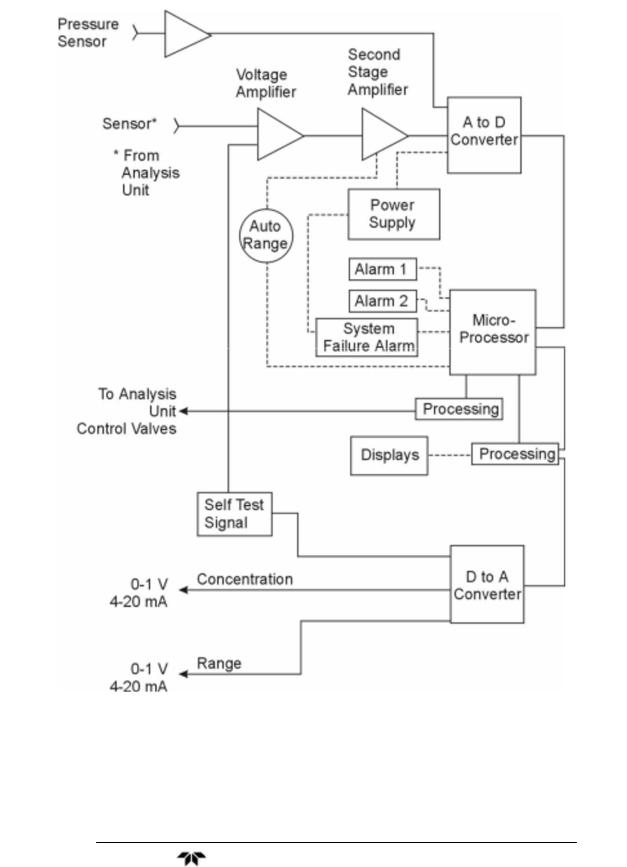
The electronic signal processing, display and control subsystem simplifies operation of the analyzer and accurately processes the sampled data. The microprocessor controls all signal processing, input/output and display functions for the analyzer. Figure 2-1 is a block diagram for the Control Unit and Figure 2-2 is a block diagram for the Analysis Unit. These diagrams indicate the functionality of each unit and the interaction between them.
Teledyne Analytical Instruments |
19 |

Part 1 Control Unit |
Model 3010MA |
|
|
|
|
Figure 2-1: Block Diagram for Model 3010MA Control Unit
Figure 2-2: Block Diagram for Model 3010MA Analysis Unit
20 |
Teledyne Analytical Instruments |
Paramagnetic O2 Purity Analyzer |
Operational Theory |
|
|
|
|
2.2 Electronics and Signal Processing
The Model 3010MAParamagnetic Oxygen Purity Analyzer uses an 8031 microcontroller with 32 kB of RAM and 128 kB of ROM to control all signal processing, input/output, and display functions for the analyzer. System power is supplied from a universal power supply module designed to be compatible with any international power source (Note: the heating system for the analysis must be set to 115V or 230V with the line voltage selector switch located on the rear Control unit). With the exception of the paramagnetic sensor, all of the system electronics are located in the Control Unit. Figure 2-3 shows the location of the temperature controller and the main electronic PC boards.
Figure 2-3: Location of Electronic Components in Control Unit
The universal power supply is located behind the temperature controller and is accessible after removing the rear panel.
The signal processing electronics including the microprocessor, analog to digital, and digital to analog converters are located on the motherboard at the bottom of the case. The preamplifier board is mounted on top of the motherboard as shown in the above figure. These boards are accessible after removing the rear panel. Figure 2-4 is a block diagram of the analyzer electronics.
Teledyne Analytical Instruments |
21 |

Part 1 Control Unit |
Model 3010MA |
|
|
|
|
When an oxygen level is present, the paramagnetic sensor in the Analysis Unit generates a voltage in the range of 0 to 1VDC. The voltage is passed to the Control Unit via the sensor cable between the Analysis Unit and the Control Unit. A voltage amplifier in the Control Unit conditions the signal and passes it to the 18-bit analog to digital (A/D) converter which is controlled by the microprocessor.
The sensor’s vent pressure from the Analysis unit is received via a 1/8 inch gas connection on the rear of the control unit. The vent pressure is then routed to the pressure transducer located on the pre-amp PCB. The output from the sensor is condition by a two-stage amplifier and passed to the A/D converter.
The concentration signal, pressure signal, and the input from the control panel are processed by the microprocessor, and appropriate control signals are directed to the display, alarms and communications port.
The same digital information is also sent to a 12 bit digital to analog converter that produces the 4-20 mA dc and the 0-1VDC analog concentration signal outputs, and the analog range ID outputs.
The microprocessor monitors the power supply, and activates the system failure alarm if a malfunction is detected.
2.5 Temperature Control
For accurate analysis this instrument is temperature controlled to provide a thermally stable environment. The analyzer must be brought to thermal equilibrium prior to analyzing any sample gas. The paramagnetic sensor is sensitive to operating temperature variations. The sensor module used in the Model 3010MA includes a pre-amp and an internal
temperature controller set to 55 C. The sensor module is also housed in an insulated temperature controlled oven within the Analysis Unit to improve thermal stability and isolate the system from any external temperature fluctuation. The oven temperature is maintained at a constant 40 C by the PID temperature controller located in the Control Unit (see Figure 2-3). Feedback to the temperature controller is by an RTD on the sensor mounting block. The oven is capable of providing a maximum of 80 Watts.
22 |
Teledyne Analytical Instruments |
Paramagnetic O2 Purity Analyzer |
Operational Theory |
|
|
|
|
Figure 2-4: Block Diagram of the Model 3010MA Electronics
Teledyne Analytical Instruments |
23 |

Part 1 Control Unit |
Model 3010MA |
|
|
|
|
24 |
Teledyne Analytical Instruments |

Paramagnetic O2 Purity Analyzer |
Installation |
|
|
|
|
Installation
Installation of the Model 3010MA Analyzer includes:
1.Unpacking
2.Mounting
3.Gas connections
4.Electrical connections
5.Testing the system.
6.Initial Sensor Calibration
This chapter covers installation of the Control Unit. The Analysis Unit installation is covered in Part II of this manual. Procedures for the Initial Sensor Calibration is given in Part II Section 6.6.
3.1 Unpacking the Analyzer
The analyzer is shipped with all the materials you need to install and prepare the system for operation. Carefully unpack the analyzer and inspect it for damage. Immediately report any damage to the shipping agent.
3.2 Mounting the Analyzer
The Model 3010MA is for indoor use in a general purpose area. It is NOT for use in hazardous environments of any type.
The standard model is designed for flush panel mounting. There are four mounting holes—one in each corner of the rigid frame. An outline drawing D73635, is included in the Drawings section in the rear of this manual which contains a panel cutout diagram.
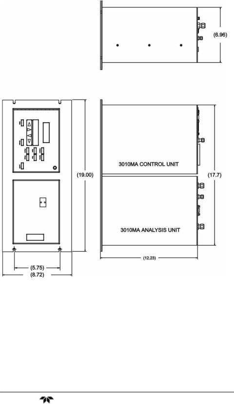
On special order, a 19" rack-mounting version can be provided. For rack mounting, the 3010MA Control Unit and Analysis Unit are flushpanel mounted side by side on the rack panel. Figure 3-1 is a drawing for a typical 19 inch rack mounted Model 3010 MA.
Teledyne Analytical Instruments |
25 |
Part 1 Control Unit |
Model 3010MA |
|
|
|
|
Figure 3-1: Rack Mountable Control and Analysis Units
26 |
Teledyne Analytical Instruments |

Paramagnetic O2 Purity Analyzer |
Installation |
|
|
|
|
All operator controls are mounted on the control panel which is shown in Figure 3-2. The panel is hinged on the left edge and doubles as a door to provides access to the display electronics, PCB’s and temperature controller inside the instrument. The door is spring loaded and will swing open when the button in the center of the latch (upper right corner) is pressed all the way in with a narrow gauge tool (less than 0.18 inch wide), such as a small hex wrench or screwdriver Allow clearance for the door to open in a 90-degree arc of radius 7.125 inches. See Figure 3-2.
Figure 3-2: Front Panel of the Model 3010MA
Figure 3-3: Required Front Door Clearance
Teledyne Analytical Instruments |
27 |
 Loading...