


Total Hydrocarbon Analyzer
INSTRUCTION, OPERATING, AND MAINTENANCE MANUAL FOR
MODEL 4020
Special Version with Modifications for
Automatic Background Gas Switching
P/N M81965
4/05/2010 Rev 6
DANGER
Toxic and/or flammable gases or liquids may be present in this monitoring system. Personal protective equipment may be required when servicing this instrument.
Hazardous voltages exist on certain components internally which may persist for a time even after the power is turned off and disconnected.
Only authorized personnel should conduct maintenance and/or servicing. Before conducting any maintenance or servicing, consult with authorized supervisor/manager.
Teledyne Analytical Instruments |
i |

Model 4020
Copyright © 2010 Teledyne Analytical Instruments
All Rights Reserved. No part of this manual may be reproduced, transmitted, transcribed, stored in a retrieval system, or translated into any other language or computer language in whole or in part, in any form or by any means, whether it be electronic, mechanical, magnetic, optical, manual, or otherwise, without the prior written consent of Teledyne Analytical Instruments, 16830 Chestnut Street, City of Industry, CA 91749-1580.
Warranty
This equipment is sold subject to the mutual agreement that it is warranted by us free from defects of material and of construction, and that our liability shall be limited to replacing or repairing at our factory (without charge, except for transportation), or at customer plant at our option, any material or construction in which defects become apparent within one year from the date of shipment, except in cases where quotations or acknowledgements provide for a shorter period. Components manufactured by others bear the warranty of their manufacturer. This warranty does not cover defects caused by wear, accident, misuse, neglect or repairs other than those performed by Teledyne or an authorized service center. We assume no liability for direct or indirect damages of any kind and the purchaser by the acceptance of the equipment will assume all liability for any damage which may result from its use or misuse.
We reserve the right to employ any suitable material in the manufacture of our apparatus, and to make any alterations in the dimensions, shape or weight of any parts, in so far as such alterations do not adversely affect our warranty.
Important Notice
This instrument provides measurement readings to its user, and serves as a tool by which valuable data can be gathered. The information provided by the instrument may assist the user in eliminating potential hazards caused by his process; however, it is essential that all personnel involved in the use of the instrument or its interface be properly trained in the process being measured, as well as all instrumentation related to it.
The safety of personnel is ultimately the responsibility of those who control process conditions. While this instrument may be able to provide early warning of imminent danger, it has no control over process conditions, and it can be misused. In particular, any alarm or control systems installed must be tested and understood, both as to how they operate and as to how they can be defeated. Any safeguards required such as locks, labels, or redundancy, must be provided by the user or specifically requested of Teledyne at the time the order is placed.
Therefore, the purchaser must be aware of the hazardous process conditions. The purchaser is responsible for the training of personnel, for providing hazard warning methods and instrumentation per the appropriate standards, and for ensuring that hazard warning devices and instrumentation are maintained and operated properly.
Teledyne Analytical Instruments, the manufacturer of this instrument, cannot accept responsibility for conditions beyond its knowledge and control. No statement expressed or implied by this document or any information disseminated by the manufacturer or its agents, is to be construed as a warranty of adequate safety control under the user’s process conditions.
|
|
|
Teledyne Analytical Instruments |
ii |
|

Total Hydrocarbon Analyzer
Specific Model Information
The instrument for which this manual was supplied may incorporate one or more options not supplied in the standard instrument. Commonly available options are listed below, with check boxes. Any that are incorporated in the instrument for which this manual is supplied are indicated by a check mark in the box.
Instrument Serial Number: _______________________
Options Included in the Instrument with the Above Serial Number:
Power Requirements: This instrument may be designed for operation using a power source other than 115 VAC @ 60 Hz. If so, one of the boxes below will be checked indicating the power requirements for your instrument.
110 VAC @ 50 Hz
115 VAC @ 50 Hz
220 VAC @ 50/60 Hz
Other: _______________
Using Hydrogen as Sample: For applications where the sample gas is hydrogen, the sample gas doubles as the fuel for combustion. The gas connections made at the back panel are slightly different for this configuration. Connect the hydrogen sample gas to the sample input as usual. Connect a nitrogen source at 40 psig to the fuel input. This is discussed in the manual in the Installation section.
Using Hydrogen as Fuel: For applications where the fuel is hydrogen, the gas connections made at the back panel are
Teledyne Analytical Instruments |
iii |

Model 4020
slightly different. At the “FUEL” inlet, replace the “40% H2/60% N2” with pure H2. This is discussed in the Installation section.
Special Analysis Ranges: this model 4020 has special analysis ranges:
Range 1: ___________
Range 2: ___________
Range 3: ___________
Auto-Calibration Module Option: This module consists of solenoid for automatically selecting calibration or sample flow to the analyzer and provides the user with the ability to calibrate the analyzer on a user-programmed schedule.
AP Options: Vented Sample System Covers; Perforated covers have been installed over the sample system compartment and analyzer top cover for venting purposes.
Recommended warm-up period: |
|
hours |
Other: |
|
|
|
|
|
Teledyne Analytical Instruments |
iv |
|
Total Hydrocarbon Analyzer
Safety Messages
Your safety and the safety of others is very important. We have provided many important safety messages in this manual. Please read these messages carefully.
A safety message alerts you to potential hazards that could hurt you or others. Each safety message is associated with a safety alert symbol. These symbols are found in the manual and inside the instrument. The definition of these symbols is described below:
No
Symbol
GENERAL WARNING/CAUTION: Refer to the instructions for details on the specific danger. These cautions warn of specific procedures which if not followed could cause bodily Injury and/or damage the instrument.
CAUTION: HOT SURFACE WARNING: This warning is
specific to heated components within the instrument. Failure to heed the warning could result in serious burns to skin and underlying tissue.
WARNING: ELECTRICAL SHOCK HAZARD: Dangerous
voltages appear within this instrument. This warning is specific to an electrical hazard existing at or nearby the component or procedure under discussion. Failure to heed this warning could result in injury and/or death from electrocution.
Technician Symbol: All operations marked with this symbol are to be performed by qualified maintenance personnel only.
NOTE: Additional information and comments regarding a specific component or procedure are highlighted in the form of a note.
STAND-BY: This symbol indicates that the instrument is on Stand-by but circuits are active.
Teledyne Analytical Instruments |
v |

Model 4020
CAUTION: THE ANALYZER SHOULD ONLY BE USED FOR THE PURPOSE AND IN THE MANNER DESCRIBED IN THIS MANUAL.
IF YOU USE THE ANALYZER IN A MANNER OTHER THAN THAT FOR WHICH IT WAS INTENDED, UNPREDICTABLE BEHAVIOR COULD RESULT POSSIBLY ACCOMPANIED WITH HAZARDOUS CONSEQUENCES.
This manual provides information designed to guide you through the installation, calibration and operation of your new analyzer. Please read this manual and keep it available.
Occasionally, some instruments are customized for a particular application or features and/or options added per customer requests. Please check the front of this manual for any additional information in the form of an Addendum which discusses specific information, procedures, cautions and warnings that may be specific to your instrument.
Manuals do get misplaced. Additional manuals can be obtained from Teledyne at the address given in the Appendix. Some of our manuals are available in electronic form via the internet. Please visit our website at: www.teledyne-ai.com.
|
|
|
Teledyne Analytical Instruments |
vi |
|

Total Hydrocarbon Analyzer
Table of Contents |
|
|
Safety Messages ........................................................................... |
v |
|
List of Figures.............................................................................. |
xii |
|
List of Tables .............................................................................. |
xiii |
|
Additional Safety Information .................................................. |
xiv |
|
Procedure for Removal of Internal Inaccessible Shock Hazards |
xvi |
|
Introduction ................................................................................... |
1 |
|
1.1 |
Main Features of the Analyzer |
1 |
1.2 |
Principle of Operation |
2 |
1.3 |
Analyzer Description |
2 |
1.4 |
Applications |
3 |
Operational Theory ....................................................................... |
7 |
|
2.1 |
Introduction |
7 |
2.2 |
Sample System |
7 |
|
2.2.1 Input Porting |
8 |
|
2.2.2 Sample Flow Control System |
8 |
|
2.2.3 Fuel and Blanket Air Systems |
9 |
|
2.2.4 Flame Ionization Detection Cell |
9 |
2.3 |
Detection Cell |
9 |
|
2.3.1 Electrometer-Amplifier |
11 |
|
2.3.2 Anode Power Supply |
11 |
|
2.3.3 Flame Guard Circuit |
12 |
|
2.3.4 Flame Ignition Circuit |
12 |
|
2.3.5 Proportional Temperature Control Circuit |
12 |
Installation ................................................................................... |
13 |
|
3.1 |
Unpacking the Analyzer |
13 |
|
Teledyne Analytical Instruments |
vii |

Model 4020
3.2 Mounting the Analyzer |
13 |
|
3.3 User Connections |
14 |
|
3.3.1 Electrical Power Connections |
14 |
|
3.3.2 Gas Connections |
14 |
|
3.3.2.1 Vent Connections |
16 |
|
3.3.3 Electrical Connections |
17 |
|
3.3.3.1 Primary Input Power |
17 |
|
3.3.3.2 Fuse Installation |
17 |
|
3.3.3.3 |
50-Pin Equipment Interface Connector |
17 |
3.3.3.4 |
Analog Output |
18 |
3.3.3.5 |
Alarm Relays |
20 |
3.3.3.6 Background Gas Selection and Digital Remote |
|
|
|
Cal Inputs |
21 |
3.3.3.7 Range ID Relays |
23 |
|
3.3.3.8 Network I/O |
23 |
|
3.3.3.9 Pin Out Table |
23 |
|
3.3.4 RS-232 Port |
25 |
|
3.3.5 Supporting Gases |
26 |
|
3.3.5.1 Sample Gas |
27 |
|
3.3.5.2 Effluent |
27 |
|
3.3.5.3 Sample Bypass Vent |
27 |
|
3.3.5.4 Fuel and Air Connections |
27 |
|
Operation ..................................................................................... 29 |
||
4.1 Equipment |
|
29 |
4.2 Preliminary Power-Off Check List |
30 |
|
4.3 Placing the System in Operation |
30 |
|
4.4 Activating the Support Gases |
31 |
|
4.4.1 Air |
|
31 |
4.4.2 Sample Gas |
31 |
|
4.4.3 Span Gas |
31 |
|
|
|
|
Teledyne Analytical Instruments |
viii |
|

Total Hydrocarbon Analyzer
4.4.4 Fuel |
31 |
4.5 Flame Ignition |
32 |
4.5.1 Verification of the Flame Guard Circuit |
32 |
4.5.2 Ignition and/or Flame Guard Circuit Failure |
33 |
4.6 Analyzer Operation |
33 |
4.6.1 Default Parameters |
34 |
4.6.2 Style Conventions |
35 |
4.6.3 Using the Controls |
35 |
4.6.4 Mode/Function Selection |
36 |
4.6.4.1 Analysis Mode |
36 |
4.6.4.2 Setup Mode |
37 |
4.6.5 Data Entry |
38 |
4.6.5.1 ENTER |
38 |
4.6.5.2 ESCAPE |
40 |
4.6.6 Setting up an AUTO-CAL |
40 |
4.6.7 Password Protection |
42 |
4.6.7.1 Entering the Password |
43 |
4.6.7.2 Installing or Changing the Password |
44 |
4.6.8 Logging Out |
45 |
4.6.9 System Self-Diagnostic Test |
45 |
4.6.10 The Model Screen |
46 |
4.6.11 Zero and Span Functions |
47 |
4.6.12 The Alarms Function |
50 |
4.6.13 The Range Function |
53 |
4.6.13.1 Manual (Select/Define Range) Screen |
53 |
4.6.13.2 Auto Range |
55 |
4.6.14 Digital Filter Setup |
56 |
4.6.15 Fuel Display |
57 |
4.6.16 Valve Selections |
57 |
4.6.16.1 Disabled |
58 |
Teledyne Analytical Instruments |
ix |

Model 4020
4.6.16.2 User Select |
|
58 |
4.6.16.3 Default (By Function) |
|
59 |
4.6.16.4 Observing the gas Stream Concentrations |
61 |
|
4.6.17 Standby |
|
62 |
4.7 Advanced User Functions |
|
62 |
4.7.1 Zero Offset Adjustment |
|
62 |
4.7.2 Background Gas Selection |
|
63 |
4.7.2.1 Manually Selecting a Background Gas |
64 |
|
4.7.2.2 Automatic Background Gas Selection |
65 |
|
4.7.2.3 Match/Invert |
|
65 |
Maintenance & Troubleshooting................................................ |
|
67 |
5.1 Measuring Circuit Electrical Checks |
68 |
|
5.1.1 Loss of Zero Control |
|
68 |
5.1.2 Anode Voltage Check |
|
69 |
5.1.3 Electronic Stability |
|
70 |
5.1.4 Printed Circuit Board Replacement |
70 |
|
5.1.5 Collector Cable |
|
70 |
5.2 Temperature Control Electronic Check |
71 |
|
5.3 Ignition and/or Flame Guard Circuit Checks |
72 |
|
5.4 Sampling System |
|
73 |
5.5 Printed Circuit Board Descriptions |
|
73 |
5.5.1 Flame Guard and Anode Power Supply PCB |
73 |
|
5.5.3 Proportional Temperature Controller PCB |
74 |
|
5.5.4 Electrometer-Amplifier PCB |
|
76 |
Appendix ...................................................................................... |
|
79 |
Specifications |
|
79 |
Application Data |
|
80 |
Recommended Spare Parts List |
|
81 |
Drawing List |
|
82 |
Index................................................... |
Error! Bookmark not defined. |
|
Teledyne Analytical Instruments |
x |
|
Total Hydrocarbon Analyzer
Teledyne Analytical Instruments |
xi |

Model 4020
List of Figures |
|
Figure 1-1: Gas Sample System with Optional AutoCal Valves |
...... 4 |
Figure 1-2: Gas Sample System Without Optional AutoCal Valves. 5 |
|
Figure 1-3: Flame Ionization Cell..................................................... |
6 |
Figure 2-1: View Inside Cabinet .................................................... |
11 |
Figure 3-1: Gas Connections......................................................... |
15 |
Figure 3-2: Equipment Interface Connector Pin Arrangement....... |
18 |
Figure 4-1: Front Panel View of Regulator and Gages.................. |
32 |
Figure 4-2: Typical VFD Screen Layout ........................................ |
35 |
Figure 4-3: Setup Mode Functions ................................................ |
39 |
Figure 4-4: AUTOCAL Screens ..................................................... |
42 |
|
|
|
Teledyne Analytical Instruments |
xii |
|

Total Hydrocarbon Analyzer
List of Tables |
|
Table 3-1: Analog Output Connections ......................................... |
18 |
Table 3-2: Analog Concentration Output—Example...................... |
19 |
Table 3-3: Analog Range ID Output—Example............................. |
20 |
Table 3-4: Alarm Relay Contact Pins ............................................ |
21 |
Table 3-5: Remote Calibration Connections.................................. |
22 |
Table 3-6: Range ID Relay Connections ....................................... |
23 |
Table 3-7: Pin out of 50 pin D-Sub Connector............................... |
23 |
Table 3-8: Commands via RS-232 Input ....................................... |
25 |
Table 3-9: Required RS-232 Options ............................................ |
26 |
Table 4-2: AL-2 Relay Status for MATCH and INVERT ................ |
66 |
Teledyne Analytical Instruments |
xiii |
Model 4020
Additional Safety Information
DANGER
COMBUSTIBLE GAS USAGE
WARNING
This is a general purpose instrument designed for usage in a non-hazardous area. It is the customer's responsibility to ensure safety especially when combustible gases are being analyzed since the potential of gas leaks always exist.
The customer should ensure that the principles of operating of this equipment are well understood by the user. Misuse of this product in any manner, tampering with its components, or unauthorized substitution of any component may adversely affect the safety of this instrument.
Since the use of this instrument is beyond the control of Teledyne, no responsibility by Teledyne, its affiliates, and agents for damage or injury from misuse or neglect of this equipment is implied or assumed.
WARNING: HYDROGEN GAS IS USED IN THIS INSTRUMENT AS A FUEL. HYDROGEN IS EXTREMELY FLAMMABLE. EXTREME CARE MUST BE USED WHEN WORKING AROUND GAS MIXTURES CONTAINING FLAMMABLE GASES.
A Successful leak check was performed at TI/AI on the sample system of this instrument prior to calibration, testing and shipping. Ensure that there are no leaks in the fuel supply lines before applying power to the system.
|
|
|
Teledyne Analytical Instruments |
xiv |
|
Total Hydrocarbon Analyzer
Always purge the entire system before performing any maintenance and always leak check the system after removing any tubing or fittings on the sample system. See the procedures for purging and leak checking this instrument on the following pages.
If toxic gases or other hazardous materials are introduced into the sample system, the same precautions regarding leak checking and purging apply to the sample lines and sample supply or delivery lines.
WARNING: ELECTRICAL SHOCK HAZARD. WITH THE EXCEPTION OF OPENING THE DOOR AND ADJUSTING THE PRESSURE REGULATORS, FLOW CONTROLLER, OR OBSERVING THE PRESSURE GAUGES AND THE FLOWMETER, ONLY AUTHORIZED AND SUITABLY TRAINED PERSONNEL SHOULD PERFORM WORK INSIDE OF THE INSTRUMENT. COMPONENTS WITHIN THE COVER ON THE INSIDE OF THE DOOR, INSIDE THE ISOTHERMAL CHAMBER (SAMPLE SYSTEM), AND ON THE ELECTROMETER-AMPLIFIER PC BOARD CONTAIN DANGEROUSLY HIGH VOLTAGE SUFFICIENT TO CAUSE SERIOUS INJURY OR DEATH.
There are the following three types of inaccessible shock hazards within the 4020:
1.Line voltages and line related voltages such as 115 VAC which exists within the 230 VAC version as well. These voltages stop when the 4020 is turned off and the mains (line) cord is removed from the instrument.
2.The sensor anode supply voltage (approximately 250 VDC). This voltage exists on the Flame Guard, anode power supply, PCB, the motherboard, and the anode/igniter terminals on the sensor. THIS VOLTAGE WILL REMAIN HAZARDOUS FOR MANY MINUTES AFTER THE MODEL 4020 HAS BEEN TURNED OFF!
Teledyne Analytical Instruments |
xv |

Model 4020
3.External hazardous voltages which may be connected to the Model 4020 alarm relay connections.
Procedure for Removal of Internal Inaccessible Shock Hazards
CAUTION: SERVICING OR MAINTENANCE OF THE 4020 SHOULD ONLY BE DONE BY SUITABLE TRAINED PERSONNEL. TO AVOID THESE INACCESSIBLE HAZARDOUS VOLTAGES WHEN SERVICING THE 4020, PERFORM EACH OF THE FOLLOWING STEPS, IN THE ORDER GIVEN, BEFORE SERVICING BEGINS:
1.Switch off the power to the 4020 and remove the mains (line) power cord from the 4020.
2.Remove all external voltages from the connections to the alarm contacts.
3.Wait one minute.
4.Discharge the anode supply voltage.
a.Connect one end of an insulated (to 1000 VDC or more) clip lead to 4020 chassis ground (the standoff for the upper right corner of the mother PCB).
b.Put one end of a 500V rated 1000 ohm resistor in the other end of the clip lead.
c.Check the voltage between chassis ground (the standoff for the upper right corner of the mother PCB) and the top side of R2 at PCB number B74671. It should be between -5VDC and +5VDC. If is in that range, the inaccessible hazardous voltage removal procedure is completed, if not repeat steps 4.a and 4.b.
If it is absolutely necessary to work inside the instrument with power on, use the ONE HAND RULE:
Work with one hand only.
Keep the other hand free without contacting any other object. This reduces the possibility of a ground path through the body in case of accidental contact with hazardous voltages.
|
|
|
Teledyne Analytical Instruments |
xvi |
|
Total Hydrocarbon Analyzer
WARNING: THIS INSTRUMENT IS DESIGNED TO BE OPERATED IN A NONHAZARDOUS AREA. THE ANALYZER USES HYDROGEN GAS AND/OR OTHER COMBUSTIBLE GASES IN ITS OPERATION. THIS EQUIPMENT, IF NOT USED AND MAINTAINED PROPERLY CAN BE AN EXPLOSION HAZARD. THE ANALYZER, DEPENDING ON THE APPLICATION, MAY ALSO USE TOXIC GASES. IT IS THEREFORE, THE CUSTOMER'S RESPONSIBILITY TO ENSURE THAT PROPER TRAINING AND UNDERSTANDING OF THE PRINCIPLES OF OPERATION OF THIS EQUIPMENT ARE UNDERSTOOD BY THE USER. SINCE THE USE OF THIS INSTRUMENT IS BEYOND THE CONTROL OF TELEDYNE, NO RESPONSIBILITY BY TELEDYNE, ITS AFFILIATES AND AGENTS FOR DAMAGE OR INJURY RESULTING FROM MISUSE OR NEGLECT OF THIS INSTRUMENT IS IMPLIED OR ASSUMED. MISUSE OF THIS PRODUCT IN ANY MANNER, TAMPERING WITH ITS COMPONENTS OR UNAUTHORIZED SUBSTITUTION OF ANY COMPONENT MAY ADVERSELY AFFECT THE SAFETY OF THIS INSTRUMENT.
CAUTION: WHEN OPERATING THIS INSTRUMENT, THE DOORS MUST BE CLOSED AND ALL COVERS SECURELY FASTENED. THE GAUGES MUST BE IN PROPER WORKING ORDER. DO NOT OVERPRESSURIZE THE SYSTEM.
READ THIS MANUAL BEFORE OPERATING THE
INSTRUMENT AND ADHERE TO ALL WARNINGS
INCLUDED IN THIS MANUAL.
Teledyne Analytical Instruments |
xvii |

Total Hydrocarbon Analyzer |
Introduction |
|
|
|
|
|
|
|
Introduction
Teledyne Analytical Instruments Model 4020 Total Hydrocarbon Analyzer is a versatile instrument designed to measure the quantity of hydrocarbons present in a positive pressure sample as equivalent methane. The Model 4020 is a microprocessor controlled digital instrument based on Teledyne’s highly successful Model 402R series analog Total Hydrocarbon Analyzer. This instrument includes special modifications for automatic switching between sample gas in two different background gases.
1.1 Main Features of the Analyzer
The Model 4020 Total Hydrocarbon Analyzer is sophisticated yet simple to use. A dual display on the front panel prompts and informs the operator during all phases of operation. The main features of the analyzer include:
Easy-to-use front panel interface that includes a red 5-digit LED display and a vacuum fluorescent display (VFD), driven by microprocessor electronics.
High resolution, accurate readings of concentration from low ppm levels to 6%.
Versatile analysis with three user-definable analysis ranges from 1 ppm through 6%.
Microprocessor based electronics: 8-bit CMOS microprocessor with 32 kB RAM and 128 kB ROM.
Autoranging allows analyzer to automatically select the proper preset range for a given measurement. Manual override allows the user to lock onto a specific range of interest.
One adjustable concentration alarm and a system failure alarm.
Manual or automatic switching between two background gas streams.
Teledyne Analytical Instruments |
1 |

Introduction |
Model 4020 |
|
|
|
|
|
|
|
Extensive self-diagnostic testing at startup and on demand with continuous power supply monitoring.
RS-232 serial digital port for use with a computer or other digital communication device.
Analog outputs for concentration and range identification (0- 1 VDC standard and isolated 4-20 mA dc).
Superior Accuracy
1.2Principle of Operation
The sample gas is mixed with a fuel (normally a composition of hydrogen and nitrogen) and burned in an atmosphere of “blanket air”. The ions formed in the burning process cause an electrical conduction between two electrodes in the combustion chamber (or detector cell) that is amplified by a highly sensitive electrometer-amplifier circuit. The electrical output of the electrometer-amplifier is directly proportional to the quantity of flame ionizable hydrocarbons present, and is linear over the range of 0-60,000 PPM methane.
1.3 Analyzer Description
The information contained in this manual describes individual analyzers of the Model 4020 standard series that includes automatic background gas switching. The versatility of this analyzer is inherited through the long heritage of the earlier analog unit. Very often, special customer driven design features are incorporated and will require additional or supplementary information in addition to the information described in this manual. These special considerations, if applicable, will be described in detail on specific application pages as Addenda to this manual. When the Model 4020 is a part of a larger system, it is subordinate to that system, and specific installation and operation conditions of that system will apply. Consult system sections of the manuals for those applications, where conditions specific to those systems will be detailed.
To best suit the needs of the purchaser, specialized designs may have been adopted. Details of the design differences may be found in the various drawings (outline, assembly, schematic, wiring, and piping diagrams) in the drawings section at the rear of the manual.
The standard analyzer is housed in a sheet steel equipment case flush-mounted in a 19" rack. The front interface panel is mounted on a
|
|
|
Teledyne Analytical Instruments |
2 |
|
Total Hydrocarbon Analyzer |
Introduction |
|
|
|
|
|
|
|
door which, when opened, allows convenient access to the 4020 electronics. The entire front panel can slide out of the chassis to provide greater access to the electronics and to the sample system. Gas pressure and flow controls are mounted on the front panel adjacent to the LED and VFD displays and user interface.
At the rear of the instrument are ports for the introduction of air, fuel, zero, span, and sample gas. A single 50-pin user-interface cable connector contains input/output, background gas switching signals and alarm signals available to the user. An RS-232 port is also available at the rear panel for connection to a remote computer or other digital communication device. The Model 4020 is set up for either 120 VAC 60 Hz or 230 50/60 Hz operation depending on the customer’s requirements. The appropriate power cord for your unit has been shipped with this instrument.
1.4Applications
Monitoring the purity of oxygen, argon, nitrogen and other gases in the manufacture of semiconductors and related equipment.
Monitoring hydrocarbon contamination in air liquefaction and other gas production processes.
Gas purity certification.
Detecting trace hydrocarbons in ambient air.
Detecting atmospheric pollutants.
Cryogenics.
Monitoring for fuel leakage or toxic solvents.
Monitoring hydrocarbons in a wide range of process streams.
Teledyne Analytical Instruments |
3 |

Introduction |
Model 4020 |
|
|
|
|
|
|
|
Figure 1-1: Gas Sample System with Optional AutoCal Valves
|
|
|
Teledyne Analytical Instruments |
4 |
|
Total Hydrocarbon Analyzer |
Introduction |
|
|
|
|
|
|
|
Figure 1-2: Gas Sample System Without Optional AutoCal Valves
Teledyne Analytical Instruments |
5 |
Introduction |
Model 4020 |
|
|
|
|
|
|
|
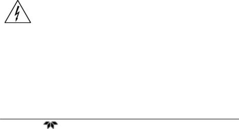
Figure 1-3: Flame Ionization Cell
|
|
|
Teledyne Analytical Instruments |
6 |
|

Total Hydrocarbon Analyzer |
Operational Theory |
|
|
|
|
|
|
|
Operational Theory
2.1 Introduction
The Model 4020 Total Hydrocarbon Analyzer is composed of three subsystems:
1.Sample System
2.Detector Cell
3.Electronic Signal Processing, Display and Control
2.2Sample System
Note: The measured component for the Model 4020 is hydrocarbon content. Hydrocarbon lubricants and conditioners, as well as synthetic plastics are common to instrumentation supply processes. Utmost precaution must be taken at all times to specify hydrocarbon-free gases, regulator diaphragms, and supplies.
All components used to control the sample and supporting gases, as well as the combustion portion of the detector cell, are located inside the enclosure, behind the electronics control panel and are accessible by sliding the front of the unit out from the rack enclosure. Adjustments are made using the appropriate control on the front panel.
The basic analyzer consists of an isothermal chamber containing the pressure regulators, pressure gauges and flow restrictors. The temperature within the chamber is maintained at 125°F by a heating element. The regulated temperature of the chamber insures stable gas flow. An optional AutoCal module is available which when fitted, mounts inside the instrument enclosure and integrates with the sample system. It allows convenient switching between sample and calibration gases. When installed, it is part of the isothermal chamber. The bypass flow is also controlled from this optional panel.
The software in the Model 4020 allows the system to be used for analyzing a sample gas in two different backgrounds, O2 and N2. A
Teledyne Analytical Instruments |
7 |

Operational Theory |
Model 4020 |
|
|
|
|
|
|
|
separate calibration must be performed on each sample/background combination. The calibration parameters are stored internally and are appropriately applied when the user selects the specific background gas in use. See Section 4.7.2 Background Gas Selection.
Note: The user must supply the necessary valves and any associated switching equipment for delivering the correct sample/background gas combination to the analyzer.
This special 4020 Analyzer includes the ability to automatically select between two background gases (N2 and O2). Additional display screens have been added and electrical modifications performed to implement and control the automatic background switching capability of this instrument.
Note: The user must supply the necessary valves and any associated switching equipment for delivering the correct sample/background gas combination to the analyzer.
2.2.1 Input Porting
The analyzer is equipped with ports for the introduction of air, fuel, zero, span, and sample gas.
2.2.2 Sample Flow Control System
Stable sample flow is achieved by maintaining a constant pressure across a restrictor through the use of a back-pressure regulation system, which includes an adjustable regulator, pressure gauge, throttle valve, and flowmeter. The throttle valve and flowmeter are included so that the bypass flow required by the back-pressure regulator can be limited. Without these controls, a high sample point pressure would result in unnecessary sample waste through the back-pressure regulator.
The components of the system are arranged so that no dead volume is present in the sample path to the detector cell. This guarantees rapid response to changes in hydrocarbon concentration—a fact that can be demonstrated when zero and span gas are exchanged during the standardization procedure.
The restrictors used in the system look alike; however, they are not interchangeable.
|
|
|
Teledyne Analytical Instruments |
8 |
|
Total Hydrocarbon Analyzer |
Operational Theory |
|
|
|
|
|
|
|
2.2.3 Fuel and Blanket Air Systems
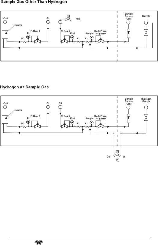
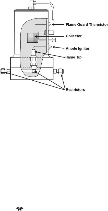
The fuel and blanket air systems use similar components. Stable flow is achieved by maintaining a constant pressure across restrictors upstream from the cell. Each system incorporates an adjustable pressure regulator, pressure gauge, and restrictor. A flame out light is included to indicate when the flame fails. A fuel shut-off solenoid valve, mounted on the line that supplies fuel, stops the fuel flow in case of flame failure. This valve is located in line with the fuel port; except for instruments using hydrogen as the sample gas. In this case, the sample is used as fuel and the valve is located in line with the sample port. See Figure 1-1 for a flow schematic for instruments equipped with AutoCal valves and Figure 1-2 for instruments without the AutoCal option.
2.2.4 Flame Ionization Detection Cell
The sample and fuel are combined within a tee fitting located in the isothermal chamber. The mixed gas is emitted from a burner within the sensor assembly. Blanket air is introduced into the sensor (or cell) by means of a separate fitting that is located in the base section of the assembly. The upper half of the assembly houses the anode-igniter, collector, and flame guard thermistor. The cell is located at the left hand front area inside the enclosure for easy access. See Figure 2.1.
2.3 Detection Cell
The upper section of the stainless steel flame ionization cell houses the cylindrical collector electrode, the high voltage (+260 VDC) anodeigniter coil, and the sensing thermistor of the flame guard circuit (see cell cross-section Figure 1-3).
WARNING: DANGEROUS HIGH VOLTAGE EXISTS AT THE ANODE IGNITER COIL (+260 VDC). DO NOT ATTEMPT TO DISCONNECT THE IGNITER COIL CABLE OR DISASSEMBLE ANY OF THE FLAME IONIZATION CELL COMPONENTS WITHOUT TURNING OFF THE POWER AND DISCONNECTING THE POWER CORD.
The collector is interconnected with the electrometer-amplifier PC board by a coaxial cable. Although the cable and fittings are intended for coaxial service, the cable is actually being used as a shielded singleconductor connection.
Teledyne Analytical Instruments |
9 |

Operational Theory |
Model 4020 |
|
|
|
|
|
|
|
The anode-igniter, as its name implies, serves two functions. When relay K2 at PCB part number B74671 is energized, the coil becomes an electrical heating element that glows red-hot and ignites the hydrogen fuel. When relay K2 at B74671 is de-energized, the coil is connected to the +260 volt DC terminal of the anode-flame guard power supply PC board. In this configuration, the necessary potential difference is established between the coil (anode) and collector to promote ionization of the burned hydrocarbons. The coil functions as the high voltage anode in all three range positions of the selector switch.
The thermistor acts as the sensor in the flame guard circuit. Its ambient temperature resistance is in the 100 K ohms region. When the flame is ignited, its resistance is reduced by a factor of 100. The thermistor is coupled to a semiconductor control circuit on the anodeflame guard power supply PC board, which will be described in a following section.
The cell electrodes of both the anode-igniter and flame guard thermistor are connected to the electronics chassis by means of a plug-in cable.
The electrode section of the cell may be removed for inspection by turning off the power, disconnecting the electrode lead plug, and removing the screws which retain the electrode assembly in the sensor body.
|
|
|
Teledyne Analytical Instruments |
10 |
|
Total Hydrocarbon Analyzer |
Operational Theory |
|
|
|
|
|
|
|
Figure 2-1: View Inside Cabinet
2.3.1 Electrometer-Amplifier
The collector cable is coupled directly to a coaxial fitting located on the electrometer-amplifier PC board. The PC board is located on the side panel next to but outside of the isothermal chamber. See Figure 2-1. and consists of an electrometer amplifier and an operational amplifier. This circuit is a very high-gain, current-to-voltage converter circuit, having an input impedance measuring in the billions of ohms. It is static sensitive and highly susceptible to contamination. Special care must be taken in handling this PC board.
Refer to Section 5.5.4: Electrometer-Amplifier PC Board for more information concerning the electrometer-amplifier and the other printed circuits that follow.
2.3.2 Anode Power Supply
The high voltage anode power supply components are mounted on the anode power supply printed circuit board. High voltage regulation is achieved through the use of series-connected zener diodes. The simplicity of this circuit’s design can be attributed to the extremely low current demand of the anode circuit. The positive output voltage is
Teledyne Analytical Instruments |
11 |

Operational Theory |
Model 4020 |
|
|
|
|
|
|
|
nominally 125 volts. Output tolerance is ±10 volts from the specified 125 volts.
2.3.3 Flame Guard Circuit
A thermistor-controlled, transistorized switching circuit is employed to operate a relay in the event of a flame-out condition. A panel indicator light and fuel shut-off solenoid valve are operated by the relay to alarm personnel that a flame-out condition has occurred. The fuel shut-off solenoid valve stops the hydrogen flow.
2.3.4 Flame Ignition Circuit
The flame ignition circuit includes the anode-igniter electrode (in the detector cell), a transformer, and processor controlled relay. The circuit is automatically energized after the warm up count down timer expires.
If automatic ignition fails, there will be a message that reports this, and the flame can be manually ignited by pressing simultaneously the Up and Down key.
2.3.5 Proportional Temperature Control Circuit
The temperature of the isothermal chamber containing the sampling components is regulated by a thermistor-directed electronic circuit. The thermistor and heating element are located in the chamber, and the balance of the circuit components are mounted on the temperature controller printed circuit board. A temperature limit switch protects the isothermal chamber against excessive temperature, which may occur if the temperature controlling system fails.
|
|
|
Teledyne Analytical Instruments |
12 |
|
 Loading...