


Operation Manual for
Model 6200T
UV Fluorescence Total Sulfur Analyzer
P/N M6200T
DATE 1/15/14
TELEDYNE ELECTRONIC TECHNOLOGIES
Analytical Instruments
16830 Chestnut Street
City of Industry, CA 91748
Telephone: (626) 934-1500
Fax: (626) 961-2538
Web: www.teledyne-ai.com
 Teledyne Analytical Instruments

Model 6200T Total Sulfur Analyzer
Copyright © 2013 Teledyne Analytical Instruments
All Rights Reserved. No part of this manual may be reproduced, transmitted, transcribed, stored in a retrieval system, or translated into any other language or computer language in whole or in part, in any form or by any means, whether it be electronic, mechanical, magnetic, optical, manual, or otherwise, without the prior written consent of Teledyne Analytical Instruments, 16830 Chestnut Street, City of Industry, CA 91748.
Warranty
This equipment is sold subject to the mutual agreement that it is warranted by us free from defects of material and of construction, and that our liability shall be limited to replacing or repairing at our factory (without charge, except for transportation), or at customer plant at our option, any material or construction in which defects become apparent within one year from the date of shipment, except in cases where quotations or acknowledgements provide for a shorter period. Components manufactured by others bear the warranty of their manufacturer. This warranty does not cover defects caused by wear, accident, misuse, neglect or repairs other than those performed by Teledyne or an authorized service center. We assume no liability for direct or indirect damages of any kind and the purchaser by the acceptance of the equipment will assume all liability for any damage which may result from its use or misuse.
We reserve the right to employ any suitable material in the manufacture of our apparatus, and to make any alterations in the dimensions, shape or weight of any parts, in so far as such alterations do not adversely affect our warranty.
Important Notice
This instrument provides measurement readings to its user, and serves as a tool by which valuable data can be gathered. The information provided by the instrument may assist the user in eliminating potential hazards caused by his process; however, it is essential that all personnel involved in the use of the instrument or its interface be properly trained in the process being measured, as well as all instrumentation related to it.
The safety of personnel is ultimately the responsibility of those who control process conditions. While this instrument may be able to provide early warning of imminent danger, it has no control over process conditions, and it can be misused. In particular, any alarm or control systems installed must be tested and understood, both as to how they operate and as to how they can be defeated. Any safeguards required such as locks, labels, or redundancy, must be provided by the user or specifically requested of Teledyne at the time the order is placed.
Therefore, the purchaser must be aware of the hazardous process conditions. The purchaser is responsible for the training of personnel, for providing hazard warning methods and instrumentation per the appropriate standards, and for ensuring that hazard warning devices and instrumentation are maintained and operated properly.
Teledyne Analytical Instruments, the manufacturer of this instrument, cannot accept responsibility for conditions beyond its knowledge and control. No statement expressed or implied by this document or any information disseminated by the manufacturer or its agents, is to be construed as a warranty of adequate safety control under the user’s process conditions.
Trademarks
All trademarks, registered trademarks, brand names or product names appearing in this document are the property of their respective owners and are used herein for identification purposes only.
ii

6200T Total Sulfur Analyzer |
Configuration |
INFORMATION ABOUT THE SPECIFIC CONFIGURATION OF YOUR MODEL 6200T TOTAL SULFUR ANALYZER
Selected Versions of the Model 6200T
Model 6200T— Standard Version
This Model 6200T Analyzer is a touch screen version designed for analyzing the total sulfur (TS) concentration in a sample gas. The analyzer includes a thermal converter to oxidize sulfur bearing molecules to SO2 which is then analyzed by the analyzer. The converter has an Oxy-Flow Sensor that provides an alarm in the event of a low flow in the combustion air inlet to the converter.
The analyzer is designed for positive pressure applications and is not equipped with an internal pump. The instrument is fitted with standard span and zero valves for switching between sample and calibration gas. Alarm relays are optional and if included, that option will be checked below.
Model 6200T — with Pump
This version is equipped with an internal pump and is designed for positive pressure applications.
Power Requirements
This Model 6200T is configured to operate from the following AC Power source:
100-120 VAC 60 Hz |
220-240 VAC 60 Hz |
100V 60 Hz |
100-120 VAC 50 Hz |
220-240 VAC 50 Hz |
100V 50 Hz |
Analog Output Signals
Analog output signals are available at A1 and A2 on the rear panel. This instrument is configured with the following analog outputs:
A1: 4-20 mA |
|
A2: 0-5 V |
A2: 4-20 mA |
Range Mode
The analyzer can be designed with a single or dual analysis ranges with auto-ranging or dual independent ranges. This analyzer is configured with the following range mode:
Single Range: |
|
|
Dual Range/Auto-ranging |
Dual Range/Independent |
|
Low |
Low |
|
Range: |
|
Range: |
High |
High |
|
Range: |
|
Range: |
Teledyne Analytical Instruments |
iii |
Configuration |
Model 6200T Total Sulfur Analyzer |
Selected Options for the Model 6200T
Calibrator Option:
This option includes a Model 702 Calibrator for precise blending of calibration gases.
Mounting Options
19” rack mounting with 26” sliders with ears 19” rack mounting with ears only
Rear Panel Gas Fittings
1/4” SS Standard 6 mm SS Optional
Valve Options
The standard unit includes internal span and zero valves. Additional valve options are as follows:
Internal Zero/Span Valves with Oven (IZS Option) Internal Zero/Span Valves with Oven and Permeation Tube.
Note: The permeation tube option installed depends on the sample gas (H2S or SO2) and the effusion rate.
Alarm Relays
The standard instrument is equipped with two configurable concentration alarms and one fixed system failure alarm.
Profibus Mounting Option
RS232 to Profibus Circuit Board: Special RS232 to Profibus PCB card for Profibus communication using the existing RS232 port.
Background Gas:
Notes:
Teledyne Analytical Instruments |
iv |

6200T Total Sulfur Analyzer |
About This Manual |
ABOUT THIS MANUAL
This manual describes operation, specifications, and maintenance for the Model 6200T.
In addition this manual contains important SAFETY messages for this instrument. It is strongly recommended that you read that operation manual in its entirety before operating the instrument.
.
Teledyne Analytical Instruments |
v |

About This Manual |
Model 6200T Total Sulfur Analyzer |
This page intentionally left blank.
Teledyne Analytical Instruments |
vi |
6200T Total Sulfur Analyzer |
Safety Messages |
SAFETY MESSAGES
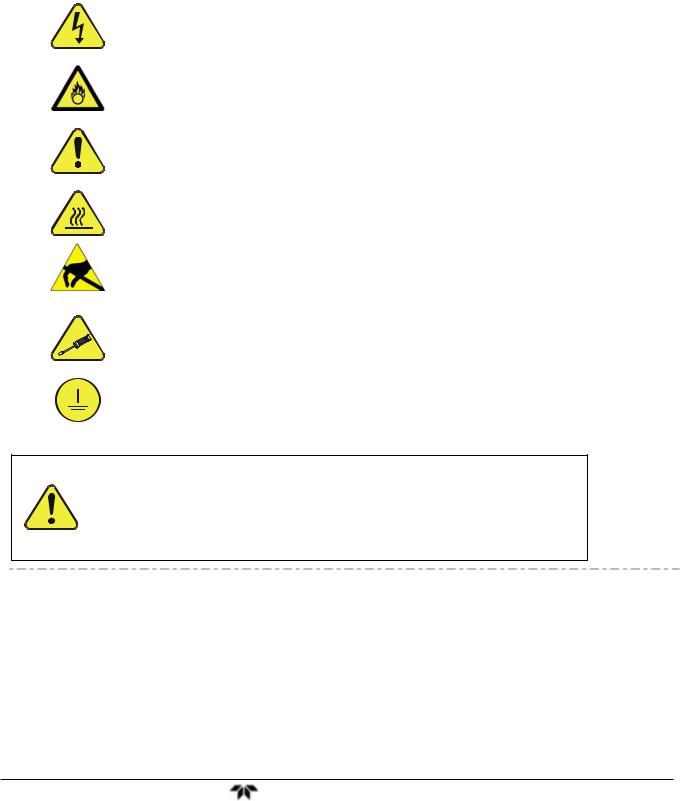
Important safety messages are provided throughout this manual for the purpose of avoiding personal injury or instrument damage. Please read these messages carefully. Each safety message is associated with a safety
alert symbol, and are placed throughout this manual; the safety symbols are also located inside the instrument. It is imperative that you pay close attention to these messages, the descriptions of which are as follows:
WARNING: Electrical Shock Hazard
HAZARD: Strong oxidizer
GENERAL WARNING/CAUTION: Read the accompanying message for specific information.
CAUTION: Hot Surface Warning
Do Not Touch: Touching some parts of the instrument without protection or proper tools could result in damage to the part(s) and/or the instrument.
Technician Symbol: All operations marked with this symbol are to be performed by qualified maintenance personnel only.
Electrical Ground: This symbol inside the instrument marks the central safety grounding point for the instrument.
CAUTION
This instrument should only be used for the purpose and in the manner described in this manual. If you use this instrument in a manner other than that for which it was intended, unpredictable behavior could ensue with possible hazardous consequences.
NEVER use any gas analyzer to sample combustible gas(es)!
Note: Technical Assistance regarding the use and maintenance of the 6200T or any other Teledyne product can be obtained by contacting Teledyne Customer Service Department:
Phone: 888-789-8168
Email: ask_tai@teledyne.com
or by accessing various service options on our website at http://www.teledyne-ai.com/
Teledyne Analytical Instruments |
vii |
Safety Messages |
Model 6200T Total Sulfur Analyzer |
CONSIGNES DE SÉCURITÉ
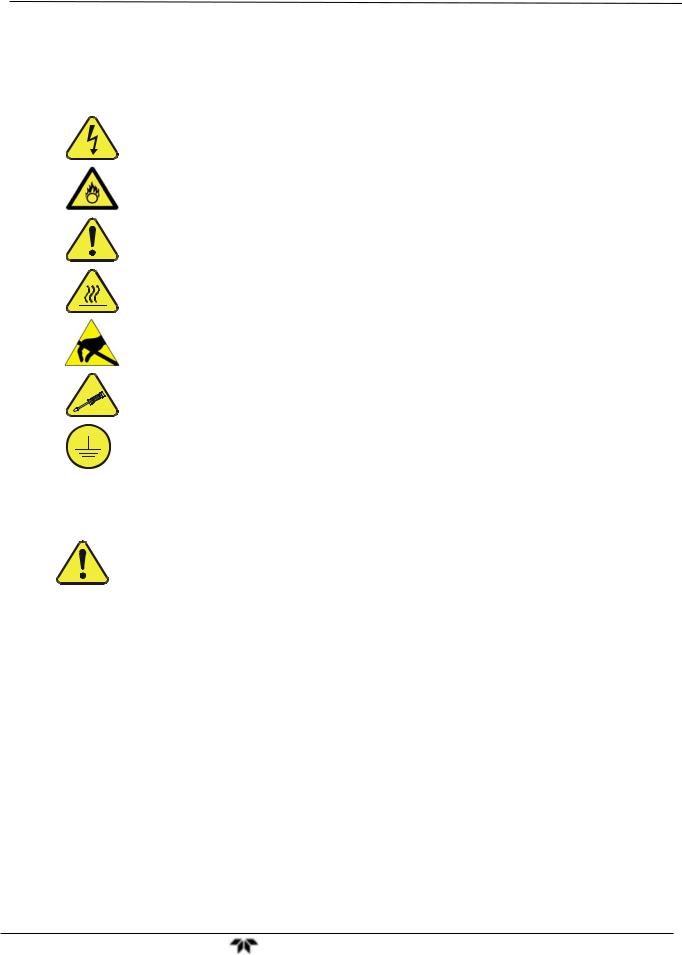
Des consignes de sécurité importantes sont fournies tout au long du présent manuel dans le but d’éviter des blessures corporelles ou d’endommager les instruments. Veuillez lire attentivement ces consignes. Chaque consigne de sécurité est représentée par un pictogramme d’alerte de sécurité; ces pictogrammes se retrouvent dans ce manuel et à l’intérieur des instruments. Les symboles correspondent aux consignes suivantes :
AVERTISSEMENT : Risque de choc électrique
DANGER : Oxydant puissant
AVERTISSEMENT GÉNÉRAL / MISE EN GARDE : Lire la consigne complémentaire pour des renseignements spécifiques
MISE EN GARDE : Surface chaude
Ne pas toucher : Toucher à certaines parties de l’instrument sans protection ou sans les outils appropriés pourrait entraîner des dommages aux pièces ou à l’instrument.
Pictogramme « technicien » : Toutes les opérations portant ce symbole doivent être effectuées uniquement par du personnel de maintenance qualifié.
Mise à la terre : Ce symbole à l’intérieur de l’instrument détermine le point central de la mise à la terre sécuritaire de l’instrument.
MISE EN GARDE
Cet instrument doit être utilisé aux fins décrites et de la manière décrite dans ce manuel. Si vous utilisez cet instrument d’une autre manière que celle pour laquelle il a été prévu, l’instrument pourrait se comporter de façon imprévisible et entraîner des conséquences dangereuses.
NE JAMAIS utiliser un analyseur de gaz pour échantillonner des gaz combustibles!
Teledyne Analytical Instruments |
viii |

6200T Total Sulfur Analyzer |
Table of Contents |
TABLE OF CONTENTS |
|
Selected Versions of the Model 6200T.............................................................................................................. |
iii |
Model 6200T— Standard Version..................................................................................................................... |
iii |
Model 6200T — with Pump............................................................................................................................... |
iii |
Power Requirements ........................................................................................................................................ |
iii |
Analog Output Signals ...................................................................................................................................... |
iii |
Range Mode...................................................................................................................................................... |
iii |
Selected Options for the Model 6200T.............................................................................................................. |
iv |
Calibrator Option:.............................................................................................................................................. |
iv |
Mounting Options....................................................................................................................................... |
iv |
Rear Panel Gas Fittings................................................................................................................................... |
iv |
Valve Options.................................................................................................................................................... |
iv |
Alarm Relays..................................................................................................................................................... |
iv |
Profibus Mounting Option ................................................................................................................................. |
iv |
Background Gas: .............................................................................................................................................. |
iv |
Notes:................................................................................................................................................................ |
iv |
SAFETY MESSAGES ............................................................................................................. |
VII |
CONSIGNES DE SÉCURITÉ ................................................................................................. |
VIII |
TABLE OF CONTENTS ........................................................................................................... |
IX |
List of Figures..................................................................................................................................................... |
xv |
List of Tables ................................................................................................................................................... |
xviii |
PART I GENERAL INFORMATION ........................................................................................ |
21 |
1. INTRODUCTION, FEATURES AND OPTIONS .................................................................. |
23 |
1.1. 6200T Overview ........................................................................................................................................... |
23 |
1.2. Features ....................................................................................................................................................... |
23 |
1.3. 6200T Documentation................................................................................................................................. |
24 |
1.4. Options......................................................................................................................................................... |
24 |
1.5. Configurations............................................................................................................................................. |
27 |
1.6. The M501TS – Total Reduced Sulfur Converter....................................................................................... |
31 |
2. SPECIFICATIONS, APPROVALS & COMPLIANCE.......................................................... |
35 |
2.1. Specifications and Approvals.................................................................................................................... |
35 |
2.2. EPA Equivalency Designation ................................................................................................................... |
37 |
2.3. CE Mark Compliance .................................................................................................................................. |
38 |
2.3.1. Emissions Compliance........................................................................................................................... |
38 |
2.3.2. Safety Compliance................................................................................................................................. |
38 |
3. GETTING STARTED........................................................................................................... |
39 |
3.1. Unpacking the 6200T Analyzer .................................................................................................................. |
39 |
3.1.1. Ventilation Clearance............................................................................................................................. |
40 |
3.2. Instrument Layout....................................................................................................................................... |
40 |
3.2.1. Front Panel ............................................................................................................................................ |
40 |
3.2.2. Rear Panel ............................................................................................................................................. |
44 |
3.2.3. Internal Chassis Layout ......................................................................................................................... |
46 |
3.3. Connections and Setup.............................................................................................................................. |
48 |
3.3.1. Electrical Connections ........................................................................................................................... |
48 |
3.3.2. Pneumatic Connections ......................................................................................................................... |
62 |
3.4. Startup, Functional Checks, and Initial Calibration................................................................................. |
74 |
3.4.1. Startup.................................................................................................................................................... |
74 |
3.4.2. Warning Messages ................................................................................................................................ |
77 |
3.4.3. Functional Checks ................................................................................................................................. |
79 |
3.4.4. Initial Calibration .................................................................................................................................... |
81 |
PART II OPERATING INSTRUCTIONS.................................................................................. |
87 |
4. OVERVIEW OF OPERATING MODES ............................................................................... |
89 |
4.1. Sample Mode ............................................................................................................................................... |
90 |
4.1.1. Test Functions ....................................................................................................................................... |
90 |
Teledyne Analytical Instruments |
ix |

Table of Contents |
Model 6200T Total Sulfur Analyzer |
|
4.1.2. Warning Messages ................................................................................................................................ |
|
93 |
4.2. Calibration Mode ......................................................................................................................................... |
|
95 |
4.3. Setup Mode.................................................................................................................................................. |
|
95 |
4.3.1. Password Security ................................................................................................................................. |
|
95 |
4.3.2. Primary Setup Menu .............................................................................................................................. |
|
96 |
4.3.3. Secondary Setup Menu (SETUP>MORE)............................................................................................. |
|
96 |
5. SETUP MENU ..................................................................................................................... |
|
97 |
5.1. SETUP – CFG: Configuration Information................................................................................................ |
|
97 |
5.2. SETUP – ACAL: Automatic Calibration Option........................................................................................ |
|
97 |
5.3. SETUP – DAS: Internal Data Acquisition System.................................................................................... |
|
97 |
5.4. SETUP – RNGE: Analog Output Reporting Range Configuration.......................................................... |
97 |
|
5.4.1. Available Analog Output Signals ........................................................................................................... |
|
98 |
5.4.2. Physical Range versus Analog Output Reporting Ranges .................................................................... |
98 |
|
5.4.3. Reporting Range Modes: Single, Dual, Auto Ranges ......................................................................... |
|
100 |
5.4.4. Range Units ......................................................................................................................................... |
|
103 |
5.4.5. Dilution Ratio (Option).......................................................................................................................... |
|
105 |
5.5. SETUP – PASS: Password Protection .................................................................................................... |
|
106 |
5.6. SETUP – CLK: Setting the Internal Time-of-Day Clock ......................................................................... |
|
109 |
5.7. SETUP – COMM: Communications Ports............................................................................................... |
|
111 |
5.7.1. ID (Instrument Identification)................................................................................................................ |
|
111 |
5.7.2. INET (Ethernet).................................................................................................................................... |
|
112 |
5.7.3. COM1 and COM2 (Mode, Baud Rate and Test Port).......................................................................... |
|
112 |
5.8. SETUP – VARS: Variables Setup and Definition.................................................................................... |
|
113 |
5.9. SETUP – DIAG: Diagnostics Functions .................................................................................................. |
|
115 |
5.9.1. Signal I/O ............................................................................................................................................. |
|
117 |
5.9.2. Analog Output Step Test...................................................................................................................... |
|
118 |
5.9.3. Analog I/O Configuration...................................................................................................................... |
|
119 |
5.9.4. Optic Test............................................................................................................................................. |
|
132 |
5.9.5. Electrical Test ...................................................................................................................................... |
|
133 |
5.9.6. Lamp Calibration.................................................................................................................................. |
|
134 |
5.9.7. Pressure Calibration ............................................................................................................................ |
|
135 |
5.9.8. Flow Calibration ................................................................................................................................... |
|
136 |
5.9.9. Test Channel Output............................................................................................................................ |
|
137 |
6. COMMUNICATIONS SETUP AND OPERATION ............................................................. |
|
139 |
6.1. Data Terminal / Communication Equipment (DTE DCE) ....................................................................... |
|
139 |
6.2. Communication Modes, Baud Rate and Port testing ............................................................................ |
|
139 |
6.2.1. Communication Modes ........................................................................................................................ |
|
140 |
6.2.2. COMM Port Baud Rate ........................................................................................................................ |
|
142 |
6.2.3. COMM Port Testing ............................................................................................................................. |
|
143 |
6.3. RS-232 ........................................................................................................................................................ |
|
143 |
6.4. RS-485 (Option) ......................................................................................................................................... |
|
144 |
6.5. Ethernet...................................................................................................................................................... |
|
144 |
6.5.1. Configuring Ethernet Communication Manually (Static IP Address) ................................................... |
144 |
|
6.5.2. Configuring Ethernet Communication Using Dynamic Host Configuration Protocol (DHCP) ............. |
147 |
|
6.5.3. USB Port .............................................................................................................................................. |
|
148 |
6.6. Communications Protocols ..................................................................................................................... |
|
149 |
6.6.1. MODBUS ............................................................................................................................................. |
|
149 |
6.6.2. HESSEN .............................................................................................................................................. |
|
151 |
7. DATA ACQUISITION SYSTEM (DAS) AND AICOM ........................................................ |
|
157 |
7.1. DAS Structure............................................................................................................................................ |
|
158 |
7.1.1. DAS Channels ..................................................................................................................................... |
|
158 |
7.1.2. DAS Parameters .................................................................................................................................. |
|
159 |
7.1.3. DAS Triggering Events ........................................................................................................................ |
|
159 |
7.2. Default DAS Channels .............................................................................................................................. |
|
160 |
7.2.1. Viewing DAS Data and Settings .......................................................................................................... |
|
162 |
7.2.2. Editing DAS Data Channels................................................................................................................. |
|
163 |
7.2.3. Trigger Events...................................................................................................................................... |
|
165 |
7.2.4. Editing DAS Parameters...................................................................................................................... |
|
166 |
Teledyne Analytical Instruments |
x |
6200T Total Sulfur Analyzer |
Table of Contents |
7.2.5. Sample Period and Report Period ....................................................................................................... |
167 |
7.2.6. Number of Records.............................................................................................................................. |
169 |
7.2.7. RS-232 Report Function ...................................................................................................................... |
171 |
7.2.8. Compact Report................................................................................................................................... |
171 |
7.2.9. Starting Date ........................................................................................................................................ |
171 |
7.2.10. Disabling/Enabling Data Channels .................................................................................................... |
171 |
7.2.11. HOLDOFF Feature ............................................................................................................................ |
173 |
7.3. AICOM Remote Control Program ............................................................................................................ |
173 |
7.4. Remote DAS Configuration via AICOM................................................................................................... |
175 |
8. REMOTE OPERATION OF THE ANALYZER................................................................... |
177 |
8.1. Remote Operation Using the External Digital I/O .................................................................................. |
177 |
8.1.1. Status Outputs ..................................................................................................................................... |
177 |
8.1.2. Control Inputs....................................................................................................................................... |
178 |
8.2. Remote Operation Using the External Serial I/O ................................................................................... |
179 |
8.2.1. Terminal Operating Modes .................................................................................................................. |
179 |
8.2.2. Help Commands in Terminal Mode ..................................................................................................... |
180 |
8.2.3. Command Syntax ................................................................................................................................ |
180 |
8.2.4. Data Types........................................................................................................................................... |
181 |
8.2.5. Status Reporting .................................................................................................................................. |
181 |
8.3. Remote Access by Modem....................................................................................................................... |
182 |
8.4. COM Port Password Security .................................................................................................................. |
184 |
8.5. Additional Communications Documentation......................................................................................... |
185 |
9. CALIBRATION PROCEDURES........................................................................................ |
187 |
9.1. Calibration Preparations .......................................................................................................................... |
187 |
9.1.1. Required Equipment, Supplies, and Expendables .............................................................................. |
187 |
9.1.2. Data Recording Devices ...................................................................................................................... |
189 |
9.2. Manual Calibration .................................................................................................................................... |
189 |
9.3. Manual Calibration Checks ...................................................................................................................... |
193 |
9.4. Manual Calibration with Zero/Span Valves............................................................................................. |
194 |
9.5. Manual Calibration with IZS Option ........................................................................................................ |
197 |
9.6. Manual Calibration Checks with IZS or Zero/Span Valves ................................................................... |
197 |
9.7. Manual Calibration in DUAL or AUTO Reporting Range Modes .......................................................... |
200 |
9.7.1. Calibration With Remote Contact Closures ......................................................................................... |
200 |
9.8. Automatic Calibration (AutoCal) ............................................................................................................. |
201 |
9.9. Calibration Quality .................................................................................................................................... |
204 |
9.10. Calibration of Optional Sensors ............................................................................................................ |
205 |
9.10.1. O2 Sensor Calibration ........................................................................................................................ |
205 |
9.10.2. CO2 Sensor Calibration...................................................................................................................... |
209 |
10. EPA PROTOCOL CALIBRATION .................................................................................. |
213 |
10.1. Calibration Requirements ...................................................................................................................... |
213 |
10.1.1. Calibration of Equipment.................................................................................................................... |
213 |
10.1.2. Data Recording Device ...................................................................................................................... |
214 |
10.1.3. Recommended Standards for Establishing Traceability.................................................................... |
215 |
10.1.4. EPA Calibration Using Permeation Tubes......................................................................................... |
215 |
10.1.5. Calibration Frequency........................................................................................................................ |
215 |
10.1.6. Record Keeping ................................................................................................................................. |
215 |
10.1.7. Summary of Quality Assurance Checks ............................................................................................ |
216 |
10.2. Level 1 Calibrations versus Level 2 Checks ........................................................................................ |
216 |
10.3. ZERO and SPAN Checks........................................................................................................................ |
218 |
10.3.1. Zero/Span Check Procedures ........................................................................................................... |
218 |
10.4. Precision Calibration Procedures and Checks.................................................................................... |
218 |
10.4.1. Precision Calibration .......................................................................................................................... |
219 |
10.4.2. Precision Check ................................................................................................................................. |
219 |
10.5. Dynamic Multipoint Span Calibration ................................................................................................... |
219 |
10.6. Special Calibration Requirements for Dual Range or Auto Range.................................................... |
220 |
10.7. References............................................................................................................................................... |
220 |
PART III MAINTENANCE AND SERVICE ........................................................................... |
223 |
Teledyne Analytical Instruments |
xi |

Table of Contents |
Model 6200T Total Sulfur Analyzer |
11. INSTRUMENT MAINTENANCE...................................................................................... |
225 |
11.1. Maintenance Schedule ........................................................................................................................... |
226 |
11.2. Predictive Diagnostics............................................................................................................................ |
227 |
11.3. Maintenance Procedures........................................................................................................................ |
228 |
11.3.1. Changing the Sample Particulate Filter ............................................................................................. |
228 |
11.3.2. Changing the IZS Permeation Tube .................................................................................................. |
229 |
11.3.3. Changing theTS and Zero Air Scrubber Materials............................................................................. |
229 |
11.3.4. Changing the Critical Flow Orifice ..................................................................................................... |
230 |
11.3.5. Checking for Light Leaks ................................................................................................................... |
231 |
11.3.6. Detailed Pressure Leak Check .......................................................................................................... |
232 |
11.3.7. Performing a Sample Flow Check ..................................................................................................... |
233 |
11.3.8. Hydrocarbon Scrubber (Kicker) ......................................................................................................... |
233 |
12. TROUBLESHOOTING & SERVICE ................................................................................ |
237 |
12.1. General Troubleshooting ....................................................................................................................... |
237 |
12.1.1. Fault Diagnostics with Warning Messages........................................................................................ |
239 |
12.1.2. Fault Diagnosis with Test Functions .................................................................................................. |
242 |
12.1.3. Using the Diagnostic Signal I/O Functions ........................................................................................ |
243 |
12.2. Status LEDs ............................................................................................................................................. |
245 |
12.2.1. Motherboard Status Indicator (Watchdog)......................................................................................... |
245 |
12.2.2. CPU Status Indicators........................................................................................................................ |
245 |
12.2.3. Relay Board Status LEDs .................................................................................................................. |
246 |
12.3. Gas Flow Problems................................................................................................................................. |
246 |
12.3.1. Zero or Low Sample Flow.................................................................................................................. |
246 |
12.3.2. High Flow ........................................................................................................................................... |
247 |
12.4. Calibration Problems.............................................................................................................................. |
247 |
12.4.1. Negative Concentrations.................................................................................................................... |
247 |
12.4.2. No Response ..................................................................................................................................... |
247 |
12.4.3. Unstable Zero and Span .................................................................................................................... |
248 |
12.4.4. Inability to Span - No SPAN Button ................................................................................................... |
248 |
12.4.5. Inability to Zero - No ZERO Button .................................................................................................... |
249 |
12.4.6. Non-Linear Response ........................................................................................................................ |
249 |
12.4.7. Discrepancy Between Analog Output and Display ............................................................................ |
249 |
12.5. Other Performance Problems ................................................................................................................ |
250 |
12.5.1. Excessive noise ................................................................................................................................. |
250 |
12.5.2. Slow Response .................................................................................................................................. |
250 |
12.5.3. The Analyzer Doesn’t Appear on the LAN or Internet ....................................................................... |
250 |
12.6. Subsystem Checkout.............................................................................................................................. |
250 |
12.6.1. AC Power Configuration .................................................................................................................... |
251 |
12.6.2. DC Power Supply............................................................................................................................... |
252 |
12.6.3. I2C Bus ............................................................................................................................................... |
252 |
12.6.4. Touch-screen Interface ...................................................................................................................... |
253 |
12.6.5. LCD Display Module .......................................................................................................................... |
253 |
12.6.6. Relay Board ....................................................................................................................................... |
253 |
12.6.7. Motherboard....................................................................................................................................... |
254 |
12.6.8. CPU.................................................................................................................................................... |
255 |
12.6.9. RS-232 Communication..................................................................................................................... |
256 |
12.6.10. Shutter System ................................................................................................................................ |
257 |
12.6.11. PMT Sensor ..................................................................................................................................... |
257 |
12.6.12. PMT Preamplifier Board................................................................................................................... |
257 |
12.6.13. PMT Temperature Control PCA....................................................................................................... |
257 |
12.6.14. High Voltage Power Supply ............................................................................................................. |
258 |
12.6.15. Pneumatic Sensor Assembly........................................................................................................... |
259 |
12.6.16. Sample Pressure ............................................................................................................................. |
259 |
12.6.17. IZS Option........................................................................................................................................ |
259 |
12.6.18. Box Temperature ............................................................................................................................. |
260 |
12.6.19. PMT Temperature............................................................................................................................ |
260 |
12.7. Service Procedures................................................................................................................................. |
261 |
12.7.1. Disk-on-Module Replacement ........................................................................................................... |
261 |
Teledyne Analytical Instruments |
xii |

6200T Total Sulfur Analyzer |
Table of Contents |
12.7.2. Sensor Module Repair & Cleaning .................................................................................................... |
262 |
12.8. M501TS Converter Maintenance............................................................................................................ |
277 |
12.8.1. Changing the Quartz Tube................................................................................................................. |
277 |
12.8.2. Checking the Converter Efficiency..................................................................................................... |
277 |
12.8.3. Sample Diluter Maintenance.............................................................................................................. |
279 |
12.8.4. Thermocouple Replacement.............................................................................................................. |
279 |
12.9. Frequently Asked Questions (FAQs) .................................................................................................... |
283 |
12.10. Technical Assistance............................................................................................................................ |
284 |
13. PRINCIPLES OF OPERATION ....................................................................................... |
285 |
13.1. Sulfur Dioxide (SO2) Sensor Principles of operation .......................................................................... |
285 |
13.1.1. SO2 Ultraviolet Fluorescence Measurement Principle....................................................................... |
285 |
13.1.2. The UV Light Path.............................................................................................................................. |
288 |
13.1.3. UV Source Lamp................................................................................................................................ |
289 |
13.1.4. The Reference Detector..................................................................................................................... |
289 |
13.1.5. The PMT ............................................................................................................................................ |
289 |
13.1.6. UV Lamp Shutter & PMT Offset......................................................................................................... |
290 |
13.1.7. Optical Filters ..................................................................................................................................... |
290 |
13.1.8. Optical Lenses ................................................................................................................................... |
293 |
13.1.9. Measurement Interferences............................................................................................................... |
294 |
13.2. Oxygen (O2) Sensor Principles of Operation ....................................................................................... |
295 |
13.2.1. Paramagnetic Measurement of O2..................................................................................................... |
295 |
13.2.2. O2 Sensor Operation within the 6200T Analyzer ............................................................................... |
296 |
13.3. Carbon Dioxide (CO2) Sensor Principles of Operation ....................................................................... |
297 |
13.3.1. NDIR Measurement of CO2 ............................................................................................................... |
297 |
13.3.2. CO2 Operation within the 6200T Analyzer......................................................................................... |
298 |
13.3.3. Electronic Operation of the CO2 Sensor ............................................................................................ |
298 |
13.4. Pneumatic Operation.............................................................................................................................. |
299 |
13.4.1. Sample Gas Flow............................................................................................................................... |
299 |
13.4.2. Flow Rate Control .............................................................................................................................. |
300 |
13.4.3. Hydrocarbon Scrubber (Kicker) ......................................................................................................... |
301 |
13.4.4. Pneumatic Sensors............................................................................................................................ |
302 |
13.5. Electronic Operation............................................................................................................................... |
303 |
13.5.1. CPU.................................................................................................................................................... |
305 |
13.5.2. Sensor Module................................................................................................................................... |
306 |
13.5.3. Photo Multiplier Tube (PMT).............................................................................................................. |
308 |
13.5.4. PMT Cooling System ......................................................................................................................... |
310 |
13.5.5. PMT Preamplifier ............................................................................................................................... |
311 |
13.5.6. Pneumatic Sensor Board................................................................................................................... |
313 |
13.5.7. Relay Board ....................................................................................................................................... |
313 |
13.5.8. Motherboard....................................................................................................................................... |
315 |
13.5.9. Analog Outputs .................................................................................................................................. |
316 |
13.5.10. External Digital I/O ........................................................................................................................... |
317 |
13.5.11. I2C Data Bus .................................................................................................................................... |
317 |
13.5.12. Power up Circuit............................................................................................................................... |
317 |
13.5.13. Power Supply/ Circuit Breaker......................................................................................................... |
317 |
13.6. Front Panel/Display Interface ................................................................................................................ |
319 |
13.6.1. LVDS Transmitter Board.................................................................................................................... |
319 |
13.6.2. Front Panel Interface PCA................................................................................................................. |
319 |
13.7. Software Operation ................................................................................................................................. |
320 |
13.7.1. Adaptive Filter .................................................................................................................................... |
320 |
13.7.2. Calibration - Slope and Offset............................................................................................................ |
321 |
13.7.3. Temperature and Pressure Compensation (TPC) Feature ............................................................... |
321 |
13.7.4. Internal Data Acquisition System (DAS) ............................................................................................ |
322 |
14. A PRIMER ON ELECTRO-STATIC DISCHARGE .......................................................... |
325 |
14.1. How Static Charges are Created ........................................................................................................... |
325 |
14.2. How Electro-Static Charges Cause Damage........................................................................................ |
326 |
14.3. Common Myths About ESD Damage .................................................................................................... |
327 |
14.4. Basic Principles of Static Control ......................................................................................................... |
328 |
Teledyne Analytical Instruments |
xiii |

Table of Contents |
Model 6200T Total Sulfur Analyzer |
|
14.4.1. General Rules .................................................................................................................................... |
|
328 |
14.5. Basic Anti-ESD Procedures for Analyzer Repair and Maintenance .................................................. |
329 |
|
14.5.1. Working at the Instrument Rack ........................................................................................................ |
|
329 |
14.5.2. Working at an Anti-ESD Work Bench ................................................................................................ |
|
330 |
14.5.3. Transferring Components Between Rack and Bench ....................................................................... |
|
330 |
14.5.4. Opening Shipments from Teledyne Analytical Instruments’s Customer Service ................................ |
331 |
|
14.5.5. Packing Components for Return to Teledyne Analytical Instruments’s Customer Service............... |
331 |
|
15. GLOSSARY..................................................................................................................... |
|
333 |
16. SPARE PARTS ............................................................................................................... |
|
337 |
16.1. Spare Parts and Expendables Lists ...................................................................................................... |
|
337 |
17. INSTRUMENT TEST & CALIBRATION RECORD ......................................................... |
|
341 |
APPENDIX A - VERSION SPECIFIC SOFTWARE DOCUMENTATION
APPENDIX B - SPARE PARTS, 6200T
APPENDIX C - REPAIR QUESTIONNAIRE, 6200T
APPENDIX D - ELECTRONIC SCHEMATICS, 6200T
Teledyne Analytical Instruments |
xiv |

6200T Total Sulfur Analyzer |
Table of Contents |
||
LIST OF FIGURES |
|
|
|
Figure 1-1: |
6200T Basic Configuration........................................................................................................... |
|
28 |
Figure 1-2: |
6200T with IZS/Permeation Tube Option .................................................................................... |
|
29 |
Figure 1-3: |
6200T with M702 Calibrator Option ............................................................................................. |
|
30 |
Figure 1-4: |
M501TS Converter Layout........................................................................................................... |
|
32 |
Figure 3-1: |
Front Panel Layout....................................................................................................................... |
|
41 |
Figure 3-2: |
Display Screen and Touch Control .............................................................................................. |
|
41 |
Figure 3-3: |
Display/Touch Control Screen Mapped to Menu Charts ............................................................ |
|
43 |
Figure 3-4: |
Rear Panel Layout—Converter and Analyzer.............................................................................. |
|
44 |
Figure 3-5A: |
Internal Layout, Basic (no Valve or Second Gas Options) .......................................................... |
|
46 |
Figure 3-6: |
Analog In Connector .................................................................................................................... |
|
49 |
Figure 3-7: |
Analog Output Connector ............................................................................................................ |
|
50 |
Figure 3-8: |
Current Loop Option Installed on the Motherboard ..................................................................... |
|
52 |
Figure 3-9: |
Status Output Connector ............................................................................................................. |
|
53 |
Figure 3-10: |
Control Input Connector............................................................................................................... |
|
55 |
Figure 3-11: |
Concentration Alarm Relay.......................................................................................................... |
|
56 |
Figure 3-12: |
Rear Panel Connector Pin-Outs for RS-232 Mode...................................................................... |
|
58 |
Figure 3-13: |
CPU Connector Pin-Outs for RS-232 Mode ................................................................................ |
|
59 |
Figure 3-14: |
JP2 Pins 21-22 on RS-232-Multidrop PCA.................................................................................. |
|
60 |
Figure 3-15: |
RS-232-Multidrop PCA Host/Analyzer Interconnect Diagram ..................................................... |
|
61 |
Figure 3-16: |
Pneumatic Connections–Basic Configuration–Using Bottled Span Gas..................................... |
|
65 |
Figure 3-17: |
Pneumatic Connections–Basic Configuration–Using Gas Dilution Calibrator |
.............................66 |
|
Figure 3-18: |
6200T Gas Flow, Basic Configuration ......................................................................................... |
|
67 |
Figure 3-19: |
Pneumatic Layout with Zero/Span Valves Option ....................................................................... |
|
68 |
Figure 3-20: |
Pneumatic Layout with IZS Options............................................................................................. |
|
69 |
Figure 3-21: |
Pneumatic Layout with O2 Sensor ............................................................................................... |
|
71 |
Figure 3-22: |
Pneumatic Layout with CO2 Sensor............................................................................................. |
|
72 |
Figure 3-23: |
Warning Messages ...................................................................................................................... |
|
77 |
Figure 3-24: |
Functional Check ......................................................................................................................... |
|
80 |
Figure 3-25: |
Reporting Range Verification....................................................................................................... |
|
82 |
Figure 3-26: |
Dilution Ratio Setup ..................................................................................................................... |
|
83 |
Figure 3-27: |
SO2 Span Gas Setting ................................................................................................................. |
|
84 |
Figure 3-28: |
Zero/Span Calibration Procedure ................................................................................................ |
|
85 |
Figure 4-1: |
Front Panel Display...................................................................................................................... |
|
89 |
Figure 4-2: |
Viewing 6200T TEST Functions .................................................................................................. |
|
92 |
Figure 4-3: |
Viewing and Clearing 6200T WARNING Messages.................................................................... |
|
94 |
Figure 5-1: |
SETUP – Configuration Information ............................................................................................ |
|
97 |
Figure 5-2: |
SETUP – Analog Output Connector ............................................................................................ |
|
98 |
Figure 5-3: |
SETUP RNGE – Reporting Range Mode .................................................................................. |
|
100 |
Figure 5-4: |
SETUP RNGE – Single Range Mode........................................................................................ |
|
101 |
Figure 5-5: |
SETUP RNGE – Dual Range Mode .......................................................................................... |
|
102 |
Figure 5-6: |
SETUP RNGE – Auto Range Mode .......................................................................................... |
|
103 |
Figure 5-7: |
SETUP RNGE – Concentration Units Selection........................................................................ |
|
104 |
Figure 5-8: |
SETUP RNGE – Dilution Ratio .................................................................................................. |
|
105 |
Figure 5-9: |
SETUP – Enable Password Security......................................................................................... |
|
107 |
Figure 5-10: |
SETUP – Enter Calibration Mode Using Password................................................................... |
|
108 |
Figure 5-11: |
SETUP – Clock .......................................................................................................................... |
|
109 |
Figure 5-12: |
SETUP – Clock Speed Variable ................................................................................................ |
|
110 |
Figure 5-13: |
SETUP – COMM Menu.............................................................................................................. |
|
111 |
Figure 5-14: |
COMM – Machine ID ................................................................................................................ |
|
112 |
Figure 5-15: |
SETUP – VARS Menu ............................................................................................................... |
|
114 |
Figure 5-16: |
DIAG Menu ................................................................................................................................ |
|
116 |
Figure 5-17: |
DIAG – Signal I/O Menu ............................................................................................................ |
|
117 |
Figure 5-18: |
DIAG – Analog Output Menu ..................................................................................................... |
|
118 |
Figure 5-19: |
DIAG – Analog I/O Configuration Menu..................................................................................... |
|
121 |
Figure 5-20: |
DIAG – Analog Output Calibration Mode................................................................................... |
|
122 |
Figure 5-21: |
DIAG – Analog Output Calibration Mode – Single Analog Channel.......................................... |
|
123 |
Teledyne Analytical Instruments |
xv |

Table of Contents |
Model 6200T Total Sulfur Analyzer |
||
Figure 5-22: |
DIAG – Analog Output – Auto Cal or Manual Cal Selection for Channels ................................ |
124 |
|
Figure 5-23: |
Setup for Calibrating Analog Outputs ........................................................................................ |
|
125 |
Figure 5-24: |
Analog Output – Voltage Adjustment......................................................................................... |
|
126 |
Figure 5-25: |
Analog Output – Offset Adjustment ........................................................................................... |
|
127 |
Figure 5-26: |
Setup for Calibrating Current Outputs ....................................................................................... |
|
128 |
Figure 5-27: |
Analog Output – Zero and Span Value Adjustment for Current Outputs................................... |
129 |
|
Figure 5-28: |
DIAG – Analog Output – AIN Calibration................................................................................... |
|
130 |
Figure 5-29. |
DIAG – Analog Inputs (Option) Configuration Menu ................................................................. |
131 |
|
Figure 5-30: |
DIAG – Optic Test...................................................................................................................... |
|
132 |
Figure 5-31: |
DIAG – Electrical Test................................................................................................................ |
|
133 |
Figure 5-32: |
DIAG – Lamp Calibration........................................................................................................... |
|
134 |
Figure 5-33: |
DIAG – Pressure Calibration ..................................................................................................... |
|
135 |
Figure 5-34: |
DIAG – Flow Calibration ............................................................................................................ |
|
136 |
Figure 5-35: |
DIAG – Test Channel Output..................................................................................................... |
|
137 |
Figure 6-1: |
COMM – Communication Modes Setup .................................................................................... |
|
141 |
Figure 6-2: |
COMM – COMM Port Baud Rate .............................................................................................. |
|
142 |
Figure 6-3: |
COMM – COM1 Test Port.......................................................................................................... |
|
143 |
Figure 6-4: |
COMM – LAN / Internet Manual Configuration.......................................................................... |
|
146 |
Figure 6-5: |
COMM – LAN / Internet Automatic Configuration...................................................................... |
|
147 |
Figure 6-6: |
COMM – Change Hostname .................................................................................................... |
|
148 |
Figure 6-7: |
COMM – Activating Hessen Protocol ........................................................................................ |
|
152 |
Figure 6-8: |
COMM – Select Hessen Protocol Type ..................................................................................... |
|
153 |
Figure 6-9: |
COMM – Select Hessen Protocol Response Mode................................................................... |
|
154 |
Figure 6-10: |
COMM – Status Flag Bit Assignment ........................................................................................ |
|
156 |
Figure 7-1: |
Default DAS Channels Setup .................................................................................................... |
|
161 |
Figure 7-2: |
DAS – Data Acquisition Menu ................................................................................................... |
|
162 |
Figure 7-3: |
DAS – Editing DAS Data Channels ........................................................................................... |
|
163 |
Figure 7-4: |
DAS – Editing Data Channel Name........................................................................................... |
|
164 |
Figure 7-5: |
DAS – Trigger Events ................................................................................................................ |
|
165 |
Figure 7-6: |
DAS – Editing DAS Parameters ................................................................................................ |
|
166 |
Figure 7-7: |
DAS – Configuring Parameters for a Specific Data Parameter ................................................. |
167 |
|
Figure 7-8: |
DAS – Define the Report Period................................................................................................ |
|
169 |
Figure 7-9: |
DAS – Edit Number of Records ................................................................................................. |
|
170 |
Figure 7-10: |
DAS – RS-232 Report Function................................................................................................. |
|
171 |
Figure 7-11: |
DAS – Disabling / Enabling Data Channels............................................................................... |
|
172 |
Figure 7-12: |
DAS – Holdoff Feature............................................................................................................... |
|
173 |
Figure 7-13: |
AICOM Remote Control Program Interface ............................................................................... |
|
174 |
Figure 7-14: |
Sample AICOM User Interface for Configuring the DAS ........................................................... |
175 |
|
Figure 7-15: |
DAS Configuration Through a Terminal Emulation Program..................................................... |
176 |
|
Figure 8-1: |
Status Output Connector ........................................................................................................... |
|
177 |
Figure 8-2: |
Control Inputs with Local 5 V Power Supply.............................................................................. |
|
179 |
Figure 8-3: |
Control Inputs with External 5 V Power Supply ......................................................................... |
|
179 |
Figure 8-4: |
COMM – Remote Access by Modem ........................................................................................ |
|
183 |
Figure 8-5: |
COMM – Initialize the Modem ................................................................................................... |
|
184 |
Figure 9-1: |
Setup for Manual Calibration without Z/S valve or IZS Option (Step 1) .................................... |
190 |
|
Figure 9-2: |
Setup for Manual Calibration without Z/S valve or IZS Option (Step 2) .................................... |
191 |
|
Figure 9-3: |
Setup for Manual Calibration without Z/S valve or IZS Option (Step 3) .................................... |
192 |
|
Figure 9-4: |
Setup for Manual Calibration Checks ........................................................................................ |
|
193 |
Figure 9-5: |
Setup for Manual Calibration with Z/S Valve Option Installed (Step 1) ..................................... |
194 |
|
Figure 9-6: |
Setup for Manual Calibration with Z/S Valve Option Installed (Step 2) ..................................... |
195 |
|
Figure 9-7: |
Setup for Manual Calibration with Z/S Valve Option Installed (Step 3) ..................................... |
196 |
|
Figure 9-8: |
Manual Calibration with IZS Option ........................................................................................... |
|
197 |
Figure 9-9: |
Setup for Manual Calibration Check with Z/S Valve or IZS Option (Step 1) ............................. |
198 |
|
Figure 9-10: |
Setup for Manual Calibration Check with Z/S Valve or IZS Option (Step 2) ............................. |
199 |
|
Figure 9-11: |
Manual Calibration in Dual/Auto Reporting Range Modes........................................................ |
200 |
|
Figure 9-12: |
AUTO CAL – User Defined Sequence....................................................................................... |
|
203 |
Figure 9-13: |
O2 Sensor Calibration Set Up ................................................................................................... |
|
205 |
Figure 9-14: |
O2 Span Gas Concentration Set Up .......................................................................................... |
|
206 |
Teledyne Analytical Instruments |
xvi |

6200T Total Sulfur Analyzer |
Table of Contents |
||
Figure 9-15: |
Activate O2 Sensor Stability Function ........................................................................................ |
207 |
|
Figure 9-16: |
O2 Zero/Span Calibration........................................................................................................... |
208 |
|
Figure 9-17: |
CO2 |
Sensor Calibration Set Up.................................................................................................. |
209 |
Figure 9-18: |
CO2 |
Span Gas Concentration Setup ......................................................................................... |
210 |
Figure 9-19: |
Activate CO2 Sensor Stability Function ..................................................................................... |
211 |
|
Figure 9-20: |
CO2 |
Zero/Span Calibration ........................................................................................................ |
212 |
Figure 10-1: |
Dynamic Multipoint Span Calibration......................................................................................... |
220 |
|
Figure 11-1: |
Sample Particulate Filter Assembly ........................................................................................... |
228 |
|
Figure 11-2: |
Critical Flow Orifice Assembly ................................................................................................... |
231 |
|
Figure 11-3: |
Simple Leak Check Fixture........................................................................................................ |
234 |
|
Figure 11-4: |
Hydrocarbon Scrubber Leak Check Setup ................................................................................ |
234 |
|
Figure 12-1: |
Viewing and Clearing Warning Messages ................................................................................. |
240 |
|
Figure 12-2: |
Example of Signal I/O Function ................................................................................................. |
244 |
|
Figure 12-3: |
CPU Status Indicator ................................................................................................................. |
245 |
|
Figure 12-4: |
Location of Relay Board Power Configuration Jumper.............................................................. |
251 |
|
Figure 12-5: |
Manual Activation of the UV Light Shutter ................................................................................. |
257 |
|
Figure 12-6: |
Sensor Module Wiring and Pneumatic Fittings.......................................................................... |
262 |
|
Figure 12-7: |
Sensor Module Mounting Screws .............................................................................................. |
263 |
|
Figure 12-8: |
Sample Chamber Mounting Bracket.......................................................................................... |
264 |
|
Figure 12-9: |
Hex Screw Between Lens Housing and Sample Chamber ....................................................... |
265 |
|
Figure 12-10: |
UV Lens Housing / Filter Housing.............................................................................................. |
266 |
|
Figure 12-11: |
PMT UV Filter Housing Disassembled ...................................................................................... |
266 |
|
Figure 12-12: |
Disassembling the Shutter Assembly ........................................................................................ |
268 |
|
Figure 12-13: |
Shutter Assembly....................................................................................................................... |
269 |
|
Figure 12-14. |
UV Lamp Adjustment................................................................................................................. |
270 |
|
Figure 12-15: |
Location of UV Reference Detector Potentiometer ................................................................... |
271 |
|
Figure 12-16: |
PMT Assembly - Exploded View................................................................................................ |
273 |
|
Figure 12-17: |
Pre-Amplifier Board (Preamp PCA) Layout ............................................................................... |
275 |
|
Figure 13-1: |
UV Absorption............................................................................................................................ |
286 |
|
Figure 13-2: |
UV Light Path............................................................................................................................. |
289 |
|
Figure 13-3: |
Source UV Lamp Construction .................................................................................................. |
289 |
|
Figure 13-4: |
Excitation Lamp UV Spectrum Before/After Filtration................................................................ |
291 |
|
Figure 13-5: |
PMT Optical Filter Bandwidth .................................................................................................... |
292 |
|
Figure 13-6: |
Effects of Focusing Source UV in Sample Chamber................................................................. |
293 |
|
Figure 13-7: |
Oxygen Sensor - Principles of Operation .................................................................................. |
296 |
|
Figure 13-8: |
CO2 Sensor Principles of Operation .......................................................................................... |
297 |
|
Figure 13-9: |
CO2 Sensor Option PCA Layout and Electronic Connections .................................................. |
298 |
|
Figure 13-10: |
Gas Flow and Location of Critical Flow Orifice.......................................................................... |
299 |
|
Figure 13-11: |
Flow Control Assembly & Critical Flow Orifice........................................................................... |
300 |
|
Figure 13-12: |
6200T Hydrocarbon Scrubber (Kicker) ...................................................................................... |
301 |
|
Figure 13-13: |
6200T Electronic Block Diagram ............................................................................................... |
303 |
|
Figure 13-14: |
CPU Board Annotated ............................................................................................................... |
305 |
|
Figure 13-15: |
6200T Sensor Module................................................................................................................ |
306 |
|
Figure 13-16: |
6200T Sample Chamber............................................................................................................ |
307 |
|
Figure 13-17: |
PMT Housing Assembly............................................................................................................. |
308 |
|
Figure 13-18: |
Basic PMT Design ..................................................................................................................... |
309 |
|
Figure 13-19: |
PMT Cooling System ................................................................................................................. |
310 |
|
Figure 13-20: |
PMT Preamp Block Diagram ..................................................................................................... |
312 |
|
Figure 13-21: |
Relay Board Status LED Locations ........................................................................................... |
314 |
|
Figure 13-22: |
Power Distribution Block Diagram ............................................................................................. |
318 |
|
Figure 13-23: |
Front Panel and Display Interface Block Diagram..................................................................... |
319 |
|
Figure 13-24: |
Basic Software Operation .......................................................................................................... |
320 |
|
Figure 13-25: |
Calibration Slope and Offset...................................................................................................... |
321 |
|
Figure 14-1: |
Triboelectric Charging................................................................................................................ |
325 |
|
Figure 14-2: |
Basic anti-ESD Work Station ..................................................................................................... |
328 |
|
Teledyne Analytical Instruments |
xvii |

Table of Contents |
Model 6200T Total Sulfur Analyzer |
||
LIST OF TABLES |
|
|
|
Table 1-1: |
Analyzer Options.......................................................................................................................... |
|
24 |
Table 1-2: |
Thermocouple Type Distinctions ................................................................................................. |
|
31 |
Table 2-1 |
6200T Basic Unit Specifications .................................................................................................. |
|
35 |
Table 2-2: |
O2 Sensor Option Specifications................................................................................................. |
|
36 |
Table 2-3: |
CO2 Sensor Option Specifications............................................................................................... |
|
36 |
Table 3-1: |
Ventilation Clearance................................................................................................................... |
|
40 |
Table 3-2: |
Display Screen and Touch Control Description........................................................................... |
|
42 |
Table 3-3: |
Rear Panel Description—Analyzer and Converter ...................................................................... |
|
45 |
Table 3-4: |
Electrical Connections References.............................................................................................. |
|
48 |
Table 3-5: |
Analog Input Pin Assignments..................................................................................................... |
|
50 |
Table 3-6: |
Analog Output Pin Assignments .................................................................................................. |
|
50 |
Table 3-7: |
Status Output Signals .................................................................................................................. |
|
54 |
Table 3-8: |
Control Input Signals.................................................................................................................... |
|
55 |
Table 3-9: |
Pneumatic Layout Reference ...................................................................................................... |
|
63 |
Table 3-10: |
Zero/Span and Sample/Cal Valve Operating States ................................................................... |
68 |
|
Table 3-11: |
IZS Valve Operating States ......................................................................................................... |
|
69 |
Table 3-12: |
NIST-SRM's Available for Traceability of SO2 Calibration Gases ............................................... |
73 |
|
Table 3-13: |
Possible Startup Warning Messages – 6200T Analyzers w/o Options ....................................... |
78 |
|
Table 3-14: |
Possible Startup Warning Messages – 6200T Analyzers with Options....................................... |
79 |
|
Table 4-1: |
Analyzer Operating Modes .......................................................................................................... |
|
89 |
Table 4-2: |
Test Functions Defined ................................................................................................................ |
|
91 |
Table 4-3: |
List of Warning Messages............................................................................................................ |
|
93 |
Table 4-4: |
Primary Setup Mode Features and Functions ............................................................................. |
|
96 |
Table 4-5: |
Secondary Setup Mode Features and Functions ........................................................................ |
|
96 |
Table 5-1: |
Password Levels........................................................................................................................ |
|
106 |
Table 5-2: |
Variable Names (VARS) Revision G.3 ...................................................................................... |
|
113 |
Table 5-3: |
6200T Diagnostic (DIAG) Functions .......................................................................................... |
|
115 |
Table 5-4: |
DIAG - Analog I/O Functions ..................................................................................................... |
|
119 |
Table 5-5: |
Analog Output Voltage Ranges ................................................................................................. |
|
119 |
Table 5-6: |
Analog Output Current Loop Range .......................................................................................... |
|
120 |
Table 5-7: |
Voltage Tolerances for Analog Output Calibration .................................................................... |
|
125 |
Table 5-8: |
Current Loop Output Calibration with Resistor .......................................................................... |
|
129 |
Table 5-9: |
Test Parameters Available for Analog Output A3 (standard configuration)............................... |
137 |
|
Table 6-1: |
COMM Port Communication Modes .......................................................................................... |
|
140 |
Table 6-2: |
Ethernet Status Indicators.......................................................................................................... |
|
144 |
Table 6-3: |
LAN/Internet Default Configuration Properties .......................................................................... |
|
145 |
Table 6-4: |
Hostname Editing Button Functions .......................................................................................... |
|
148 |
Table 6-5: |
RS-232 Communication Parameters for Hessen Protocol ........................................................ |
151 |
|
Table 6-6: |
6200T Hessen Protocol Response Modes ................................................................................ |
|
154 |
Table 6-7: |
Default Hessen Status Bit Assignments .................................................................................... |
|
154 |
Table 7-1: |
Front Panel LED Status Indicators for DAS............................................................................... |
|
157 |
Table 7-2: |
DAS Data Channel Properties ................................................................................................... |
|
158 |
Table 7-3: |
DAS Data Parameter Functions ................................................................................................ |
|
159 |
Table 8-1: |
Status Output Pin Assignments ................................................................................................. |
|
178 |
Table 8-2: |
Control Input Pin Assignments .................................................................................................. |
|
178 |
Table 8-3: |
Terminal Mode Software Commands ........................................................................................ |
|
180 |
Table 8-4: |
Command Types........................................................................................................................ |
|
180 |
Table 8-5: |
Serial Interface Documents........................................................................................................ |
|
185 |
Table 9-1: |
NIST-SRM's Available for Traceability of SO2 Calibration Gases ............................................. |
189 |
|
Table 9-2: |
AutoCal Modes .......................................................................................................................... |
|
201 |
Table 9-3: |
AutoCal Attribute Setup Parameters.......................................................................................... |
|
201 |
Table 9-4: |
Example Auto-Cal Sequence..................................................................................................... |
|
202 |
Table 9-5: |
Calibration Data Quality Evaluation ........................................................................................... |
|
204 |
Table 10-1: |
Activity Matrix for Calibration Equipment & Supplies................................................................. |
214 |
|
Table 10-2: |
Activity Matrix for Calibration Procedure.................................................................................... |
|
214 |
Table 10-3: |
Activity Matrix for Quality Assurance Checks ............................................................................ |
|
216 |
Teledyne Analytical Instruments |
xviii |

6200T Total Sulfur Analyzer |
Table of Contents |
|
Table 10-4: |
Definition of Level 1 and Level 2 Zero and Span Checks.......................................................... |
217 |
Table 11-1: |
6200T Preventive Maintenance Schedule ................................................................................. |
226 |
Table 11-2: |
Predictive Uses for Test Functions ............................................................................................ |
227 |
Table 12-1: |
Warning Messages - Indicated Failures .................................................................................... |
240 |
Table 12-2: |
Test Functions - Possible Causes for Out-Of-Range Values .................................................... |
242 |
Table 12-3: |
Relay Board Status LEDs .......................................................................................................... |
246 |
Table 12-4: |
DC Power Test Point and Wiring Color Code............................................................................ |
252 |
Table 12-5: |
DC Power Supply Acceptable Levels ........................................................................................ |
252 |
Table 12-6: |
Relay Board Control Devices..................................................................................................... |
253 |
Table 12-7: |
Analog Output Test Function - Nominal Values ........................................................................ |
254 |
Table 12-8: |
Status Outputs Check Pin Out................................................................................................... |
255 |
Table 12-9: |
Example of HVPS Power Supply Outputs ................................................................................. |
259 |
Table 12-10: |
UV Lamp Signal Troubleshooting .............................................................................................. |
270 |
Table 13-1: |
Relay Board Status LED’s ......................................................................................................... |
314 |
Table 14-1: |
Static Generation Voltages for Typical Activities ....................................................................... |
326 |
Table 14-2: |
Sensitivity of Electronic Devices to Damage by ESD ................................................................ |
326 |
Table 16-2. |
6200E Expendables Kit, PN062610100 (Reference: 5/2/2011 15:18) ..................................... |
339 |
Table 16-3. |
6200EU Expendables Kit, PN062610200 (Reference 5/2/2011 15:27) .................................... |
340 |
Table 17-1. |
Final Test and Calibration Values for 6200T ............................................................................. |
342 |
Table 17-2. |
Test and Calibration Values for 6200TU.................................................................................... |
343 |
Table 17-3. |
Test and Calibrations Values w/ CO2 where applicable............................................................ |
344 |
Teledyne Analytical Instruments |
xix |
6200T Total Sulfur Analyzer |
Part I |
PART I
GENERAL INFORMATION
Teledyne Analytical Instruments |
21 |

Part I |
Model 6200T Total Sulfur Analyzer |
This page intentionally left blank.
Teledyne Analytical Instruments |
22 |

6200T Total Sulfur Analyzer |
Introduction |
1. INTRODUCTION, FEATURES AND OPTIONS
This section provides an overview of the Model 6200T Analyzer, its features and its options, followed by a description of how this user manual is arranged.
1.1. 6200T Overview
The 6200T consists of two major assemblies: a modified 6400T SO2 analyzer and an M501TS thermal converter. The Model 6200T is a microprocessor controlled UV Fluorescence Total Sulfur Analyzer used to measure the total sulfur (TS) concentration as sulfur dioxide (SO2) after first thermally converting the sulfur components of the sample gas to SO2. When operating in TS mode, sample is drawn into the analyzer and passed to the thermal converter. After conversion, the sample returns to the analyzer and is drawn through the instrument’s sample chamber where it is exposed to ultraviolet light, which causes any SO2 present to fluoresce. The analyzer measures the amount of fluorescence to determine the amount of SO2 present in the sample gas. In SO2 mode, the analyzer measures the sample without sending it though the converter, hnce only SO2 is meaured. The mode is user switchable from the touch screen display panel.
The 6200T’s exceptional stability is achieved with the use of an optical shutter to compensate for sensor drift and a reference detector to correct for changes in UV lamp intensity. Additionally an advanced optical design combined with a special scrubber, called a "kicker" that removes hydrocarbons (which fluoresces similarly to SO2) prevents inaccuracies due to interferents.
Calibration of the instrument is performed in software which stores SO2 concentration measurements made gas with when specific, known concentrations of SO2 are supplied to the analyzer. The microprocessor uses these calibration values along with other performance parameters such as the sensor offset, UV lamp intensity and the amount of stray light present and measurements of the temperature and pressure of the sample gas to compute the final SO2 concentration.
Built-in data acquisition capability, using the analyzer's internal memory, allows the logging of multiple parameters including averaged or instantaneous concentration values, calibration data, and operating parameters such as pressure and flow rate. Stored data are easily retrieved through the serial port or optional Ethernet port via Teledyne’s AICOM software or from the front panel, allowing operators to perform predictive diagnostics and enhanced data analysis by tracking parameter trends. Multiple averaging periods of one minute to 365 days are available for over a period of one year.
1.2. Features
The features of your 6200T UV Fluorescence Sulfur Dioxide Analyzer include:
LCD Graphical User Interface with capacitive touch screen
Ranges, 0-50 ppb to 0-20,000 ppb, user selectable
Dual ranges and auto ranging
Microprocessor control for versatility
Multi-tasking software to allow viewing test variables while operating
Continuous self checking with alarms
Bi-directional USB, RS-232, and 10/100Base-T Ethernet ports for remote operation (optional RS-485)
Teledyne Analytical Instruments |
23 |

Introduction |
Model 6200T Total Sulfur Analyzer |
Front panel USB ports for peripheral devices
Digital status outputs to indicate instrument operating condition
Adaptive signal filtering to optimize response time
Temperature and Pressure compensation
Internal Zero and Span check (optional)
Internal data logging with 1 min to 365 day multiple averages
Critical flow orifices to provide flow stability
1.3.6200T Documentation
In addition to this operation manual, two other manuals are available for download from a Teledyne website at http://www.teledyne-api.com/manuals/ to support the operation of this instrument:.
AICOM software manual, part number 03945
DAS Manual, part number 02837
1.4. Options
The options available for your analyzer are presented in Table 1-1 with name, option number, a description and/or comments, and if applicable, cross-references to technical details in this manual, such as setup and calibration. See also pages iii and iv for specific options included in your analyzer. To order these options or to learn more about them, please contact the Sales department of Teledyne Analytical Instruments at:
TOLL-FREE: |
(888) 789-8168 |
TEL: |
(626) 934-1500 |
FAX: |
(626) 961-2538 |
E-MAIL: |
ask_tai@teledyne.com |
WEB SITE: |
http://www.teledyne-ai.com/ |
Table 1-1: Analyzer Options
|
OPTION |
|
OPTION |
|
DESCRIPTION/NOTES |
|
REFERENCE |
||
|
|
NUMBER |
|
|
|||||
|
|
|
|
|
|
|
|
|
|
|
|
|
|
|
|
|
|
|
|
|
Pumps |
|
|
|
|
Pumps meet all typical AC power supply standards while exhibiting same pneumatic |
|||
|
|
|
|
|
performance. |
|
|
||
|
|
|
|
|
|
|
|
||
|
|
|
|
10A |
|
External Pump 100V - 120V @ 60 Hz |
|
N/A |
|
|
|
|
|
10B |
|
External Pump 220V - 240V @ 50 Hz |
|
N/A |
|
|
|
|
|
10C |
|
External Pump 220V - 240V @ 60 Hz |
|
N/A |
|
|
|
|
|
|
|
|
|
|
|
|
|
|
|
10D |
|
External Pump 100V – 12V @ 50 Hz |
|
N/A |
|
|
|
|
|
|
|
|
|
|
|
|
|
|
|
10E |
|
External Pump 100V @ 60 Hz |
|
N/A |
|
|
|
|
|
11B |
|
Pumpless, internal or external Pump Pack |
|
N/A |
|
|
|
|
13 |
|
High Voltage Internal Pump 240V @ 50Hz |
|
N/A |
||
|
Rack Mount |
|
|
|
Options for mounting the analyzer in standard 19” racks |
|
|
|
|
|
Kits |
|
|
|
|
|
|
||
|
|
|
|
|
|
|
|
||
|
|
|
|
20A |
|
Rack mount brackets with 26 in. chassis slides |
|
N/A |
|
|
|
|
|
|
|
|
|
|
|
|
|
|
|
20B |
|
Rack mount brackets with 24 in. chassis slides |
|
N/A |
|
Teledyne Analytical Instruments |
24 |

|
6200T Total Sulfur Analyzer |
Introduction |
|||||||
|
|
|
|
|
|
|
|
|
|
|
|
OPTION |
OPTION |
DESCRIPTION/NOTES |
REFERENCE |
||||
|
|
NUMBER |
|||||||
|
|
|
|
|
|
|
|
||
|
|
|
|
21 |
|
Rack mount brackets only (compatible with carrying strap, Option 29) |
N/A |
|
|
|
|
|
|
23 |
|
Rack mount for external pump pack (no slides) |
N/A |
||
|
|
|
|
|
|
|
|
||
|
|
Carrying Strap/Handle |
Side-mounted strap for hand-carrying analyzer |
|
|
|
|||
|
|
|
|
|
|
Extends from “flat” position to accommodate hand for carrying. |
|
|
|
|
|
|
|
29 |
|
Recesses to 9mm (3/8”) dimension for storage. |
N/A |
||
|
|
|
|
|
Can be used with rack mount brackets, Option 21. |
||||
|
|
|
|
|
|
|
|
|
|
|
|
|
|
|
|
Cannot be used with rack mount slides. |
|
|
|
|
|
|
|
|
|
CAUTION |
|
|
|
|
|
|
|
|
|
General Safety Hazard |
|
|
|
|
|
|
|
|
|
A FULLY LOADED 6200T WITH VALVE OPTIONS WEIGHS |
|
|
|
|
|
|
|
|
|
ABOUT 18 KG (40 POUNDS). |
|
|
|
|
|
|
|
|
|
TO AVOID PERSONAL INJURY WE RECOMMEND THAT TWO |
|
|
|
|
|
|
|
|
|
PERSONS LIFT AND CARRY THE ANALYZER. DISCONNECT ALL |
|
|
|
|
|
|
|
|
|
CABLES AND TUBING FROM THE ANALYZER BEFORE MOVING |
|
|
|
|
|
|
|
|
|
IT. |
|
|
|
|
|
Analog Inputs |
|
|
Used for connecting external voltage signals from other instrumentation (such as |
|
|||
|
|
|
|
meteorological instruments). |
|
|
|
||
|
|
|
|
|
|
|
|
|
|
|
|
|
|
64 |
|
Also can be used for logging these signals in the analyzer’s internal |
Sections 3.3.1.2 |
||
|
|
|
|
|
DAS |
and 6.6 |
|
||
|
|
|
|
|
|
||||
|
|
Current Loop Analog |
Adds isolated, voltage-to-current conversion circuitry to the analyzer’s analog |
|
|||||
|
|
Outputs |
|
|
outputs. |
|
|
|
|
|
|
|
|
|
|
Can be configured for any output range between 0 and 20 mA. |
Sections 3.3.1.4, |
||
|
|
|
|
41 |
|
May be ordered separately for any of the analog outputs. |
5.4.1, 5.9.3, and |
||
|
|
|
|
|
|
Can be installed at the factory or retrofitted in the field. |
5.9.3.5 |
|
|
|
|
Parts Kits |
|
|
Spare parts and expendables |
|
|
|
|
|
|
|
|
|
|
Expendables Kit includes a recommended set of expendables for |
|
|
|
|
|
|
|
42A |
one year of operation of this instrument including replacement sample |
Appendix B |
|||
|
|
|
|
|
|
particulate filters. |
|
|
|
|
|
|
|
43 |
|
Expendables Kit with IZS includes the items needed to refurbish the |
Appendix B |
||
|
|
|
|
|
internal zero air scrubber (IZS) that is included. |
||||
|
|
|
|
|
|
|
|
|
|
|
|
|
|
45 |
|
Spare Parts Kit includes spares parts for one unit. |
Appendix B |
||
|
|
NO Optical Filter |
|
|
Recommended for high NOX backgrounds. |
|
|
|
|
|
|
|
|
47 |
|
Required for EN Certification. |
N/A |
|
|
|
|
Calibration Valves |
|
Used to control the flow of calibration gases generated from external sources, rather |
|
||||
|
|
|
than manually switching the rear panel pneumatic connections. |
|
|
|
|||
|
|
|
|
|
|
|
|
|
|
|
Two Teflon® solenoid valve sets located inside the analyzer: |
50A |
Zero/Span valve switches between zero air and span gas; |
|
Sample/Cal valve switches between sample gas and calibration gas. |
Sections 3.3.2.3, 3.3.2.4, 9.4, 9.5 and 9.6
Internal Zero/Span (IZS) |
Generates internal zero air and span gas. |
|
Gas Generator |
|
|
|
|
Includes heated enclosure for a permeation tube (tube not included – see SO2 IZS Permeation Tubes options), an external scrubber for
51A producing zero air and a set of valves for switching between the sample gas inlet and the output of the zero/span subsystem, functionally very similar to the valves included in the zero/span valve option.
Sections 3.3.2.4, 9.5, 11.3.2 and 12.6.17
Teledyne Analytical Instruments |
25 |

Introduction |
|
|
Model 6200T Total Sulfur Analyzer |
||
|
|
|
|
|
|
|
OPTION |
OPTION |
|
DESCRIPTION/NOTES |
REFERENCE |
|
NUMBER |
|
|||
|
|
|
|
|
|
|
SO2 IZS Permeation Tubes |
|
Replacement tubes for the IZS option; identical size/shape; different effusion rates. |
||
|
|
|
|
|
|
|
|
Effusion Rate (@ 50°C) |
Approximate |
Specified Flow Rate (of |
|
|
|
Concentration |
indicated perm tube rate) |
||
|
|
|
|||
|
52C |
796 ng/min |
0.3-0.5 ppm |
0.76 |
± 5% lpm |
|
52H |
1592 ng/min |
0.8 ppm |
0.76 |
± 50% lpm |
|
52M |
220 ng/min |
150 ppb |
0.56 |
± 25% lpm |
|
|
|
|
|
|
Each tube comes with a calibration certificate, traceable to a NIST standard, specifying its actual effusion rate of that tube to within ± 5% when immersed in a gas stream moving at the specified flow rate. This calibration is performed at a tube temperature of 50°C.
N/A
N/A
N/A
Sections 3.3.2.4, 9.1.1.3 and 10.1.4
Communication Cables |
|
For remote serial, network and Internet communication with the analyzer. |
||||
|
|
|
Type |
Description |
|
|
|
|
|
|
Shielded, straight-through DB-9F to DB-25M cable, about |
Section 3.3.1.8 |
|
|
60A |
|
RS-232 |
1.8 m long. Used to interface with older computers or code |
||
|
|
and 6.3 |
||||
|
|
|
|
activated switches with DB-25 serial connectors. |
||
|
|
|
|
|
|
|
|
60B |
|
RS-232 |
Shielded, straight-through DB-9F to DB-9F cable of about |
Sections 3.3.1.8, |
|
|
|
1.8 m length. |
and 6.3, and 7.2.7 |
|||
|
|
|
|
|||
|
60C |
|
Ethernet |
Patch cable, 2 meters long, used for Internet and LAN |
Sections 3.3.1.8 |
|
|
|
communications. |
and 6.5 |
|||
|
|
|
|
|||
|
60D |
|
USB |
Cable for direct connection between instrument (rear panel |
Sections3.3.1.8 |
|
|
|
USB port) and personal computer. |
and 6.5.1 |
|||
|
|
|
|
|||
Concentration Alarm |
|
Issues warning when gas concentration exceeds limits set by user. |
|
|||
Relay |
|
|
||||
|
|
|
|
|
||
|
|
|
Four (4) “dry contact” relays on the rear panel of the instrument. This |
Sections 3.3.1.7 |
||
61 |
|
relay option is different from and in addition to the “Contact Closures” |
and 3.4.4 |
|||
|
|
|
that come standard on all TAI instruments. |
|
|
|
|
|
|
||||
RS-232 Multidrop |
|
Enables communications between host computer and up to eight analyzers. |
||||
62 |
|
Multidrop card seated on the analyzer’s CPU card. |
Section 3.3.1.8 |
|||
|
Each instrument in the multidrop network requires this card and a |
|||||
|
|
|
communications cable (Option 60B). |
|
|
|
Second Gas Sensors |
|
Choice of one additional gas sensor. |
|
|
||
|
|
|
|
|
• Section 2.1 (specs) |
|
|
|
|
|
|
• Section 3.3.2.8, |
|
|
|
|
|
|
(pneumatic layout) |
|
|
65A |
|
Oxygen (O2) Sensor |
• Section 9.10.1 |
||
|
|
(calibration) |
||||
|
|
|
|
|
||
|
|
|
|
|
• Section 13.2 for |
|
|
|
|
|
|
principles of |
|
|
|
|
|
|
operation |
|
|
|
|
|
|
• Section 2.1 (specs) |
|
|
|
|
|
|
• Section 3.3.2.9 |
|
|
|
|
|
|
(pneumatic layout) |
|
|
67A |
|
Carbon Dioxide (CO2) Sensor |
• Section 9.10.2 |
||
|
|
(calibration) |
||||
|
|
|
|
|
||
|
|
|
|
|
• Section 13.3 |
|
|
|
|
|
|
(principles of |
|
|
|
|
|
|
operation) |
|
Special Features |
|
Built in features, software activated |
|
|
||
|
|
|
Maintenance Mode Switch, located inside the instrument, places the |
|
|
|
|
N/A |
|
analyzer in maintenance mode where it can continue sampling, yet |
N/A |
||
|
|
ignore calibration, diagnostic, and reset instrument commands. This |
||||
|
|
|
|
|
||
|
|
|
feature is of particular use for instruments connected to Multidrop or |
|
|
|
Teledyne Analytical Instruments |
26 |

|
6200T Total Sulfur Analyzer |
Introduction |
|||
|
|
|
|
|
|
|
OPTION |
OPTION |
DESCRIPTION/NOTES |
REFERENCE |
|
|
NUMBER |
|
|||
|
|
|
|
|
|
|
|
|
Hessen protocol networks. |
|
|
|
|
|
Call Customer Service for activation. |
|
|
|
|
|
|
|
|
|
|
|
Second Language Switch activates an alternate set of display |
|
|
|
|
N/A |
messages in a language other than the instrument’s default language. |
N/A |
|
|
|
Call Customer Service for a specially programmed Disk on Module containing |
|
||
|
|
|
|
|
|
|
|
|
the second language. |
|
|
|
|
|
|
|
|
|
|
|
Dilution Ratio Option allows the user to compensate for diluted |
|
|
|
|
|
sample gas, such as in continuous emission monitoring (CEM) where |
Section 3.4.4.1, |
|
|
|
N/A |
the quality of gas in a smoke stack is being tested and the sampling |
|
|
|
|
5.4.5 and 13.1.9.3 |
|
||
|
|
|
method used to remove the gas from the stack dilutes the gas. |
|
|
|
|
|
|
|
|
|
|
|
Call Customer Service for activation. |
|
|
|
|
|
|
|
|
1.5. Configurations
There are three configurations available: the standard analyzer and two with options. The standard unit consists of:
A modified 6400T Fluorescent SO2 Analyzer
The M501TS High Temperature Thermal Converter
External Span, Internal Zero with High-performance Charcoal Scrubber for Zero.
See Figure 1-1 for the pneumatic diagram, and Section 1.6 for details on the M501TS. Another configuration consists of:
Standard unit (described above)
Internal Zero/Span (IZS) Option with H2S permeation tube.
The IZS option uses sample gas (passed through a special, high-performance charcoal scrubber) to dilute H2S from the perm tube for span calibration checks. See Figure 1-2 for the pneumatic diagram.
The third configuration consists of:
Standard unit (described above)
External M702 calibrator
The M702 calibrator option blends tanks of H2S span gas with the processed CO2.
See Figure 1-3 for the pneumatic diagram.
Teledyne Analytical Instruments |
27 |
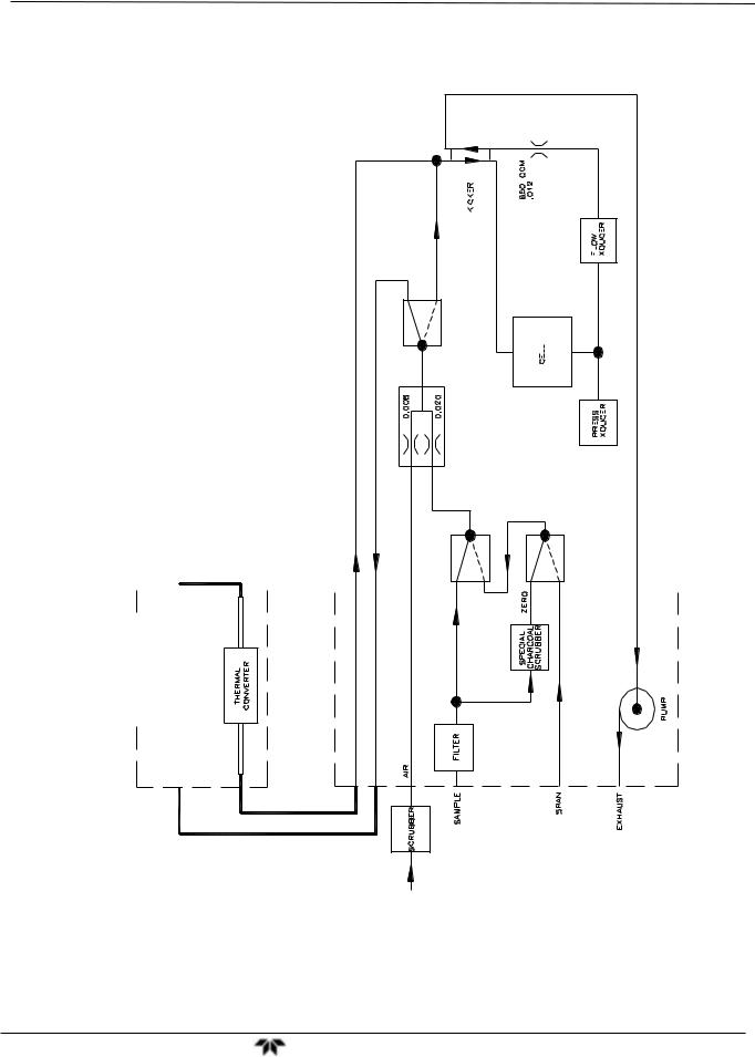
Introduction |
|
|
|
|
|
|
|
|
Model 6200T Total Sulfur Analyzer |
||||||||||||||||||||||||||||||||||||
|
|
|
|
|
|
|
|
|
|
|
|
|
|
|
|
|
|
|
|
|
|
|
|
|
|
|
|
|
|
|
|
|
|
|
|
|
|
|
|
|
|
|
|
|
|
|
|
|
|
|
|
|
|
|
|
|
|
|
|
|
|
|
|
|
|
|
|
|
|
|
|
|
|
|
|
|
|
|
|
|
|
|
|
|
|
|
|
|
|
|
|
|
|
|
|
|
|
|
|
|
|
|
|
|
|
|
|
|
|
|
|
|
|
|
|
|
|
|
|
|
|
|
|
|
|
|
|
|
|
|
|
|
|
|
|
|
|
|
|
|
|
|
|
|
|
|
|
|
|
|
|
|
|
|
|
|
|
|
|
|
|
|
|
|
|
|
|
|
|
|
|
|
|
|
|
|
|
|
|
|
|
|
|
|
|
|
|
|
|
|
|
|
|
|
|
|
|
|
|
|
|
|
|
|
|
|
|
|
|
|
|
|
|
|
|
|
|
|
|
|
|
|
|
|
|
|
|
|
|
|
|
|
|
|
|
|
|
|
|
|
|
|
|
|
|
|
|
|
|
|
|
|
|
|
|
|
|
|
|
|
|
|
|
|
|
|
|
|
|
|
|
|
|
|
|
|
|
|
|
|
|
|
|
|
|
|
|
|
|
|
|
|
|
|
|
|
|
|
|
|
|
|
|
|
|
|
|
|
|
|
|
|
|
|
|
|
|
|
|
|
|
|
|
|
|
|
|
|
|
|
|
|
|
|
|
|
|
|
|
|
|
|
|
|
|
|
|
|
|
|
|
|
|
|
|
|
|
|
|
|
|
|
|
|
|
|
|
|
|
|
|
|
|
|
|
|
|
|
|
|
|
|
|
|
|
|
|
|
|
|
|
|
|
|
|
|
|
|
|
|
|
|
|
|
|
|
|
|
|
|
|
|
|
|
|
|
|
|
|
|
|
|
|
|
|
|
|
|
|
|
|
|
|
|
|
|
|
|
|
|
|
|
|
|
|
|
|
|
|
|
|
|
|
|
|
|
|
|
|
|
|
|
|
|
|
|
|
|
|
|
|
|
|
|
|
|
|
|
|
|
|
|
|
|
|
|
|
|
|
|
|
|
|
|
|
|
|
|
|
|
|
|
|
|
|
|
|
|
|
|
|
|
|
|
|
|
|
|
|
|
|
|
|
|
|
|
|
|
|
|
|
|
|
|
|
|
|
|
|
|
|
|
|
|
|
|
|
|
|
|
|
|
|
|
|
|
|
|
|
|
|
|
|
|
|
|
|
|
|
|
|
|
|
|
|
|
|
|
|
|
|
|
|
|
|
|
|
|
|
|
|
|
|
|
|
|
|
|
|
|
|
|
|
|
|
|
|
|
|
|
|
|
|
|
|
|
|
|
|
|
|
|
|
|
|
|
|
|
|
|
|
|
|
|
|
|
|
|
|
|
|
|
|
|
|
|
|
|
|
|
|
|
|
|
|
|
|
|
|
|
|
|
|
|
|
|
|
|
|
|
|
|
|
|
|
|
|
|
|
|
|
|
|
|
|
|
|
|
|
|
|
|
|
|
|
|
|
|
|
|
|
|
|
|
|
|
|
|
|
|
|
|
|
|
|
|
|
|
|
|
|
|
|
|
|
|
|
|
|
|
|
|
|
|
|
|
|
|
|
|
|
|
|
|
|
|
|
|
|
|
|
|
|
|
|
|
|
|
|
|
|
|
|
|
|
|
|
|
|
|
|
|
|
|
|
|
|
|
|
|
|
|
|
|
|
|
|
|
|
|
|
|
|
|
|
|
|
|
|
|
|
|
|
|
|
|
|
|
|
|
|
|
|
|
|
|
|
|
|
|
|
|
|
|
|
|
|
|
|
|
|
|
|
|
|
|
|
|
|
|
|
|
|
|
|
|
|
|
|
|
|
|
|
|
|
|
|
|
|
|
|
|
|
|
|
|
|
|
|
|
|
|
|
|
|
|
|
|
|
|
|
|
|
|
|
|
|
|
|
|
|
|
|
|
|
|
|
|
|
|
|
|
|
|
|
|
|
|
|
|
|
|
|
|
|
|
|
|
|
|
|
|
|
|
|
|
|
|
|
|
|
|
|
|
|
|
|
|
|
|
|
|
|
|
|
|
|
|
|
|
|
|
|
|
|
|
|
|
|
|
|
|
|
|
|
|
|
|
|
|
|
|
|
|
|
|
|
|
|
|
|
|
|
|
|
|
|
|
|
|
|
|
|
|
|
|
|
|
|
|
|
|
|
|
|
|
|
|
|
|
|
|
|
|
|
|
|
|
|
|
|
|
|
|
|
|
|
|
|
|
|
|
|
|
|
|
|
|
|
|
|
|
|
|
|
|
|
|
|
|
|
|
|
|
|
|
|
|
|
|
|
|
|
|
|
|
|
|
|
|
|
|
|
|
|
|
|
|
|
|
|
|
|
|
|
|
|
|
|
|
|
|
|
|
|
|
|
|
|
|
|
|
|
|
|
|
|
|
|
|
|
|
|
|
|
|
|
|
|
|
|
|
|
|
|
|
|
|
|
|
|
|
|
|
|
|
|
|
|
|
|
|
|
|
|
|
|
|
|
|
|
|
|
|
|
|
|
|
|
|
|
|
|
|
|
|
|
|
|
|
|
|
|
|
|
|
|
|
|
|
|
|
|
|
|
|
|
|
|
|
|
|
|
|
|
|
|
|
|
|
|
|
|
|
|
|
|
|
|
|
|
|
|
|
|
|
|
|
|
|
|
|
|
|
|
|
|
|
|
|
|
|
|
|
|
|
|
|
|
|
|
|
|
|
|
|
|
|
|
|
|
|
|
|
|
|
|
|
|
|
|
|
|
|
|
|
|
|
|
|
|
|
|
|
|
|
|
|
|
|
|
|
|
|
|
|
|
|
|
|
|
|
|
|
|
|
|
|
|
|
|
|
|
|
|
|
|
|
|
|
|
|
|
|
|
|
|
|
|
|
|
|
|
|
|
|
|
|
|
|
|
|
|
|
|
|
|
|
|
|
|
|
|
|
|
|
|
|
|
|
|
|
|
|
|
|
|
|
|
|
|
|
|
|
|
|
|
|
|
|
|
|
|
|
|
|
|
|
|
|
|
|
|
|
|
|
|
|
|
|
|
|
|
|
|
|
|
|
|
|
|
|
|
|
|
|
|
|
|
|
|
|
|
|
|
|
|
|
|
|
|
|
|
|
|
|
|
|
|
|
|
|
|
|
|
|
|
|
|
|
|
|
|
|
|
|
|
|
|
|
|
|
|
|
|
|
|
|
|
|
|
|
|
|
|
|
|
|
|
|
|
|
|
|
|
|
|
|
|
|
|
|
|
|
|
|
|
|
|
|
|
|
|
|
|
|
|
|
|
|
|
|
|
|
|
|
|
|
|
|
|
|
|
|
|
|
|
|
|
|
|
|
|
|
|
|
|
|
|
|
|
|
|
|
|
|
|
|
|
|
|
|
|
|
|
|
|
|
|
|
|
|
|
|
|
|
|
|
|
|
|
|
|
|
|
|
|
|
|
|
|
|
|
|
|
|
|
|
|
|
|
|
|
|
|
|
|
|
|
|
|
|
|
|
|
|
|
|
|
|
|
|
|
|
|
|
|
|
|
|
|
|
|
|
|
|
|
|
|
|
|
|
|
|
|
|
|
|
|
|
|
|
|
|
|
|
|
|
|
|
|
|
|
|
|
|
|
|
|
|
|
|
|
|
|
|
|
|
|
|
|
|
|
|
|
|
|
|
|
|
|
|
|
|
|
|
|
|
|
|
|
|
|
|
|
|
|
|
|
|
|
|
|
|
|
|
|
|
|
|
|
|
|
|
|
|
|
|
|
|
|
|
|
|
|
|
|
|
|
|
|
|
|
|
|
|
|
|
|
|
|
|
|
|
|
|
|
|
|
|
|
|
|
|
|
|
|
|
|
|
|
|
|
|
|
|
|
|
|
|
|
|
|
|
|
|
|
|
|
|
|
|
|
|
|
|
|
|
|
|
|
|
|
|
|
|
|
|
|
|
|
|
|
|
|
|
|
|
|
|
|
|
|
|
|
|
|
|
|
|
|
|
|
|
|
|
|
|
|
|
|
|
|
|
|
|
|
|
|
|
|
|
|
|
|
|
|
|
|
|
|
|
|
|
|
|
|
|
|
|
|
|
|
|
|
|
|
|
|
|
|
|
|
|
|
|
|
|
|
|
|
|
|
|
|
|
|
|
|
|
|
|
|
|
|
|
|
|
|
|
|
|
|
|
|
|
|
|
|
|
|
|
|
|
|
|
|
|
|
|
|
|
|
|
|
|
|
|
|
|
|
|
|
|
|
|
|
|
|
|
|
 M501 TS
Figure 1-1: 6200T Basic Configuration
Teledyne Analytical Instruments |
28 |
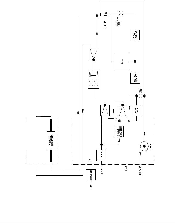
6200T Total Sulfur Analyzer |
|
|
|
|
|
|
|
|
|
|
|
|
|
|
|
|
|
|
|
|
|
|
|
|
|
|
|
|
|
|
|
|
|
|
|
|
|
|
Introduction |
|||||||||||
|
|
|
|
|
|
|
|
|
|
|
|
|
|
|
|
|
|
|
|
|
|
|
|
|
|
|
|
|
|
|
|
|
|
|
|
|
|
|
|
|
|
|
|
|
|
|
|
|
|
|
|
|
|
|
|
|
|
|
|
|
|
|
|
|
|
|
|
|
|
|
|
|
|
|
|
|
|
|
|
|
|
|
|
|
|
|
|
|
|
|
|
|
|
|
|
|
|
|
|
|
|
|
|
|
|
|
|
|
|
|
|
|
|
|
|
|
|
|
|
|
|
|
|
|
|
|
|
|
|
|
|
|
|
|
|
|
|
|
|
|
|
|
|
|
|
|
|
|
|
|
|
|
|
|
|
|
|
|
|
|
|
|
|
|
|
|
|
|
|
|
|
|
|
|
|
|
|
|
|
|
|
|
|
|
|
|
|
|
|
|
|
|
|
|
|
|
|
|
|
|
|
|
|
|
|
|
|
|
|
|
|
|
|
|
|
|
|
|
|
|
|
|
|
|
|
|
|
|
|
|
|
|
|
|
|
|
|
|
|
|
|
|
|
|
|
|
|
|
|
|
|
|
|
|
|
|
|
|
|
|
|
|
|
|
|
|
|
|
|
|
|
|
|
|
|
|
|
|
|
|
|
|
|
|
|
|
|
|
|
|
|
|
|
|
|
|
|
|
|
|
|
|
|
|
|
|
|
|
|
|
|
|
|
|
|
|
|
|
|
|
|
|
|
|
|
|
|
|
|
|
|
|
|
|
|
|
|
|
|
|
|
|
|
|
|
|
|
|
|
|
|
|
|
|
|
|
|
|
|
|
|
|
|
|
|
|
|
|
|
|
|
|
|
|
|
|
|
|
|
|
|
|
|
|
|
|
|
|
|
|
|
|
|
|
|
|
|
|
|
|
|
|
|
|
|
|
|
|
|
|
|
|
|
|
|
|
|
|
|
|
|
|
|
|
|
|
|
|
|
|
|
|
|
|
|
|
|
|
|
|
|
|
|
|
|
|
|
|
|
|
|
|
|
|
|
|
|
|
|
|
|
|
|
|
|
|
|
|
|
|
|
|
|
|
|
|
|
|
|
|
|
|
|
|
|
|
|
|
|
|
|
|
|
|
|
|
|
|
|
|
|
|
|
|
|
|
|
|
|
|
|
|
|
|
|
|
|
|
|
|
|
|
|
|
|
|
|
|
|
|
|
|
|
|
|
|
|
|
|
|
|
|
|
|
|
|
|
|
|
|
|
|
|
|
|
|
|
|
|
|
|
|
|
|
|
|
|
|
|
|
|
|
|
|
|
|
|
|
|
|
|
|
|
|
|
|
|
|
|
|
|
|
|
|
|
|
|
|
|
|
|
|
|
|
|
|
|
|
|
|
|
|
|
|
|
|
|
|
|
|
|
|
|
|
|
|
|
|
|
|
|
|
|
|
|
|
|
|
|
|
|
|
|
|
|
|
|
|
|
|
|
|
|
|
|
|
|
|
|
|
|
|
|
|
|
|
|
|
|
|
|
|
|
|
|
|
|
|
|
|
|
|
|
|
|
|
|
|
|
|
|
|
|
|
|
|
|
|
|
|
|
|
|
|
|
|
|
|
|
|
|
|
|
|
|
|
|
|
|
|
|
|
|
|
|
|
|
|
|
|
|
|
|
|
|
|
|
|
|
|
|
|
|
|
|
|
|
|
|
|
|
|
|
|
|
|
|
|
|
|
|
|
|
|
|
|
|
|
|
|
|
|
|
|
|
|
|
|
|
|
|
|
|
|
|
|
|
|
|
|
|
|
|
|
|
|
|
|
|
|
|
|
|
|
|
|
|
|
|
|
|
|
|
|
|
|
|
|
|
|
|
|
|
|
|
|
|
|
|
|
|
|
|
|
|
|
|
|
|
|
|
|
|
|
|
|
|
|
|
|
|
|
|
|
|
|
|
|
|
|
|
|
|
|
|
|
|
|
|
|
|
|
|
|
|
|
|
|
|
|
|
|
|
|
|
|
|
|
|
|
|
|
|
|
|
|
|
|
|
|
|
|
|
|
|
|
|
|
|
|
|
|
|
|
|
|
|
|
|
|
|
|
|
|
|
|
|
|
|
|
|
|
|
|
|
|
|
|
|
|
|
|
|
|
|
|
|
|
|
|
|
|
|
|
|
|
|
|
|
|
|
|
|
|
|
|
|
|
|
|
|
|
|
|
|
|
|
|
|
|
|
|
|
|
|
|
|
|
|
|
|
|
|
|
|
|
|
|
|
|
|
|
|
|
|
|
|
|
|
|
|
|
|
|
|
|
|
|
|
|
|
|
|
|
|
|
|
|
|
|
|
|
|
|
|
|
|
|
|
|
|
|
|
|
|
|
|
|
|
|
|
|
|
|
|
|
|
|
|
|
|
|
|
|
|
|
|
|
|
|
|
|
|
|
|
|
|
|
|
|
|
|
|
|
|
|
|
|
|
|
|
|
|
|
|
|
|
|
|
|
|
|
|
|
|
|
|
|
|
|
|
|
|
|
|
|
|
|
|
|
|
|
|
|
|
|
|
|
|
|
|
|
|
|
|
|
|
|
|
|
|
|
|
|
|
|
|
|
|
|
|
|
|
|
|
|
|
|
|
|
|
|
|
|
|
|
|
|
|
|
|
|
|
|
|
|
|
|
|
|
|
|
|
|
|
|
|
|
|
|
|
|
|
|
|
|
|
|
|
|
|
|
|
|
|
|
|
|
|
|
|
|
|
|
|
|
|
|
|
|
|
|
|
|
|
|
|
|
|
|
|
|
|
|
|
|
|
|
|
|
|
|
|
|
|
|
|
|
|
|
|
|
|
|
|
|
|
|
|
|
|
|
|
|
|
|
|
|
|
|
|
|
|
|
|
|
|
|
|
|
|
|
|
|
|
|
|
|
|
|
|
|
|
|
|
|
|
|
|
|
|
|
|
|
|
|
|
|
|
|
|
|
|
|
|
|
|
|
|
|
|
|
|
|
|
|
|
|
|
|
|
|
|
|
|
|
|
|
|
|
|
|
|
|
|
|
|
|
|
|
|
|
|
|
|
|
|
|
|
|
|
|
|
|
|
|
|
|
|
|
|
|
|
|
|
|
|
|
|
|
|
|
|
|
|
|
|
|
|
|
|
|
|
|
|
|
|
|
|
|
|
|
|
|
|
|
|
|
|
|
|
|
|
|
|
|
|
|
|
|
|
|
|
|
|
|
|
|
|
|
|
|
|
|
|
|
|
|
|
|
|
|
|
|
|
|
|
|
|
|
|
|
|
|
|
|
|
|
|
|
|
|
|
|
|
|
|
|
|
|
|
|
|
|
|
|
|
|
|
|
|
|
|
|
|
|
|
|
|
|
|
|
|
|
|
|
|
|
|
|
|
|
|
|
|
|
|
|
|
|
|
|
|
|
|
|
|
|
|
|
|
|
|
|
|
|
|
|
|
|
|
|
|
|
|
|
|
|
|
|
|
|
|
|
|
|
|
|
|
|
|
|
|
|
|
|
|
|
|
|
|
|
|
|
|
|
|
|
|
|
|
|
|
|
|
|
|
|
|
|
|
|
|
|
|
|
|
|
|
|
|
|
|
|
|
|
|
|
|
|
|
|
|
|
|
|
|
|
|
|
|
|
|
|
|
|
|
|
|
|
|
|
|
|
|
|
|
|
|
|
|
|
|
|
|
|
|
|
|
|
|
|
|
|
|
|
|
|
|
|
|
|
|
|
|
|
|
|
|
|
|
|
|
|
|
|
|
|
|
|
|
|
|
|
|
|
|
|
|
|
|
|
|
|
|
|
|
|
|
|
|
|
|
|
|
|
|
|
|
|
|
|
|
|
|
|
|
|
|
|
|
|
|
|
|
|
|
|
|
|
|
|
|
|
|
|
|
|
|
|
|
|
|
|
|
|
|
|
|
|
|
|
|
|
|
|
|
|
|
|
|
|
|
|
|
|
|
|
|
|
|
|
|
|
|
|
|
|
|
|
|
|
|
|
|
|
|
|
|
|
|
|
|
|
|
|
|
|
|
|
|
|
|
|
|
|
|
|
|
|
|
|
|
|
|
|
|
|
|
|
|
|
|
|
|
|
|
|
|
|
|
|
|
|
|
|
|
|
|
|
|
|
|
|
|
|
|
|
|
|
|
|
|
|
|
|
|
|
|
|
|
|
|
|
|
|
|
|
|
|
|
|
|
|
|
|
|
|
|
|
|
|
|
|
|
|
|
|
|
|
|
|
|
|
|
|
|
|
|
|
|
|
|
|
|
|
|
|
|
|
|
|
|
|
|
|
|
|
|
|
|
|
|
|
|
|
|
|
|
|
|
|
|
|
|
|
|
|
|
|
|
|
|
|
|
|
|
|
|
|
|
|
|
|
|
|
|
|
|
|
|
|
|
|
|
|
|
|
|
|
|
|
|
|
|
|
|
|
|
|
|
|
|
|
|
|
|
|
|
|
|
|
|
|
|
|
|
|
|
|
|
|
|
|
|
|
|
|
|
|
|
|
|
|
|
|
|
|
|
|
|
|
|
|
|
|
|
|
|
|
|
|
|
|
|
|
|
|
|
|
|
|
|
|
|
|
|
|
|
|
|
|
|
|
|
|
|
|
|
|
|
|
|
|
|
|
|
|
|
|
|
|
|
|
|
|
|
|
|
|
|
|
|
|
|
|
|
|
|
|
|
|
|
|
|
|
|
|
|
|
|
|
|
|
|
|
|
|
|
|
|
|
|
|
|
|
|
|
|
|
|
|
|
|
|
|
|
|
|
|
|
|
|
|
|
|
|
|
|
|
|
|
|
|
|
|
|
|
|
|
|
|
|
|
|
|
|
|
|
|
|
|
|
|
|
|
|
|
|
|
|
|
|
|
|
|
|
|
|
|
|
|
|
|
|
|
|
|
|
|
|
|
|
|
|
|
|
|
|
|
|
|
 M501 TS
Figure 1-2: 6200T with IZS/Permeation Tube Option
Teledyne Analytical Instruments |
29 |

Introduction |
|
|
|
|
|
|
|
|
|
|
|
|
Model 6200T Total Sulfur Analyzer |
||||||||||||||||
|
|
|
|
|
|
|
|
|
|
|
|
|
|
|
|
|
|
|
|
|
|
|
|
|
|
|
|
|
|
|
|
|
|
|
|
|
|
|
|
|
|
|
|
|
|
|
|
|
|
|
|
|
|
|
|
|
|
|
|
|
|
|
|
|
|
|
|
|
|
|
|
|
|
|
|
|
|
|
|
|
|
|
|
|
|
|
|
|
|
|
|
|
|
|
|
|
|
|
|
|
|
|
|
|
|
|
|
|
|
|
|
|
|
|
|
|
|
|
|
|
|
|
|
|
|
|
|
|
|
|
|
|
|
|
|
|
|
|
|
|
|
|
|
|
|
|
|
|
|
|
|
|
|
|
|
|
|
|
|
|
|
|
|
|
|
|
|
|
|
|
|
|
|
|
|
|
|
|
|
|
|
|
|
|
|
|
|
|
|
|
|
|
|
|
|
|
|
|
|
|
|
|
|
|
|
|
|
|
|
|
|
|
|
|
|
|
|
|
|
|
|
|
|
|
|
|
|
|
|
|
|
|
|
|
|
|
|
|
|
|
|
|
|
|
|
|
|
|
|
|
|
|
|
|
|
|
|
|
|
|
|
|
|
|
|
|
|
|
|
|
|
|
|
|
|
|
|
|
|
|
|
|
|
|
|
|
|
|
|
|
|
|
|
|
|
|
|
|
|
 M501 TS
Figure 1-3: 6200T with M702 Calibrator Option
Teledyne Analytical Instruments |
30 |
 Loading...