


 Loading...
Model 633
Aethalometer®
Black Carbon Monitor
User Manual
© TELEDYNE ADVANCED POLLUTION INSTRUMENTATION
9480 CARROLL PARK DRIVE
SAN DIEGO, CA 92121-5201
USA
Toll-free Phone: |
800-324-5190 |
Phone: |
858-657-9800 |
Fax: |
858-657-9816 |
Email: |
api-sales@teledyne.com |
Website: |
http://www.teledyne-api.com/ |
Copyright 2012-2013 |
07645A DCN6170 |
Teledyne Advanced Pollution Instrumentation |
23 April 2013 |
NOTICE OF COPYRIGHT
© 2013 Teledyne Advanced Pollution Instrumentation, user manual expanded and edited with permission from Aerosol d.o.o./Magee Scientific. All rights reserved.
TRADEMARKS
The Aethalometer® is a registered trademark of Magee Scientific and the instrument is manufactured by Aerosol d.o.o. in Slovenia. All other trademarks, registered trademarks, brand names or product names appearing in this document are the property of their respective owners and are used herein for identification purposes only.
07645A DCN6170 |
i |
Model 633 Aethalometer® Black Carbon Monitor User Manual |
Teledyne Advanced Pollution Instrumentation |
This page intentionally left blank.
ii |
07645A DCN6170 |
TABLE OF CONTENTS
1 INTRODUCTION |
5 |
||
1.1 |
Description |
5 |
|
1.1.1 ‘DualSpot™’ Technology |
6 |
||
1.1.2 Automatic Zero and Span |
10 |
||
1.1.3 |
User and Communications Interfaces |
11 |
|
1.1.4 |
Modular Construction |
12 |
|
1.2 |
Technical Specifications |
13 |
|
1.3 |
Functional Description |
14 |
|
2 SAFETY NOTES and LABELS |
21 |
|
3. INSTRUMENT INSTALLATION |
25 |
|
3.1 |
Unpacking the system |
25 |
3.2 |
The sampling line |
25 |
3.3 |
Powering on the Aethalometer |
27 |
3.4 |
Filter tape installation |
29 |
3.4 |
Manually lifting/lowering chamber optical head |
36 |
4 USER INTERFACE, SETTINGS and OPERATION |
37 |
|
4.1 |
User interface and settings |
37 |
4.2 |
Instrument Status |
39 |
Single Status Condition |
40 |
|
Multiple Status Conditions |
40 |
|
4.3 |
Downloading and Viewing Data |
40 |
4.4Data file structure and description of the fields |
41 |
|
|
|
|
|
Connecting to External Datalogger or PC |
43 |
4.5 |
Serial Commands for Communication with the Aethalometer |
44 |
4.6 |
External Devices |
45 |
5 MAINTENANCE and SERVICE |
47 |
|
5.1 |
Cleaning the cyclone |
48 |
5.2 |
Leak test |
50 |
5.3 |
Automatic flow meter calibration |
51 |
|
|
|
07645A DCN6170 |
iii |
|
Model 633 Aethalometer® Black Carbon Monitor User Manual |
Teledyne Advanced Pollution Instrumentation |
5.4 |
Manual flow meter calibration |
55 |
5.5 |
Manual stability test |
61 |
5.5 |
Manual clean air test |
61 |
5.6 |
Cleaning the optical head |
62 |
5.7 |
Changing the bypass cartridge filter |
65 |
5.8 |
Calibrating the tape sensor |
68 |
6 TECHNICAL SUPPORT and CONTACT INFORMATION |
71 |
|
7 SPARE PARTS LIST |
73 |
|
iv |
07645A DCN6170 |
1 INTRODUCTION
1.1 Description
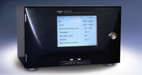
Figure 1. The Aethalometer® Model 633.
The Model 633 represents the “Next Generation” version of the real time Aethalometer rack mount instrument to measure Black Carbon (BC) particles in air. Please refer to the original Magee Scientific Aethalometer manual for a full description and background information on the method (http://mageesci.com/images/stories/docs/Aethalometer_book_2005.07.03.pdf).
The Model 633 Aethalometer incorporates scientific and technical advances designed to offer improved measurement performance versus previous versions of the Aethalometer and other BC instruments, user features, communications and interface, and the ability to perform routine performance tests to verify correct operation. Most importantly, the instrument incorporates the patented DualSpot™ measurement method. This provides two significant advantages: elimination of the changes in response due to ‘aerosol loading’ effects; and a real time calculation of the ‘loading compensation’ parameter which offers insights into aerosol optical properties, and has been interpreted in models of aerosol origins and aging.
07645A DCN6170 |
5 |
Model 633 Aethalometer® Black Carbon Monitor User Manual |
Teledyne Advanced Pollution Instrumentation |
The Model 633 Aethalometer has been developed with input from the research and monitoring communities, and is designed for reliable operation under all conditions ranging from state of the art research to compliance monitoring.
The leading innovations incorporated into the Model 633 include:
The DualSpot™ measurement method, which solves the effects common to all filter based real time monitors, in which the instrumental response factor shows a dependence on the loading of material on the filter.
Features for automatic ‘dynamic zero’ testing under a flow of internally generated clean air; ‘span’ testing of the response of the optical sources and detectors; calibration of the response of the internal mass flow meters, if an external standard flow calibrator is connected; and validation of the photometric response by use of a kit of ‘Neutral Density’ optical filters whose properties may be traced to reference standards.
User and communications interfaces, permitting remote monitoring of operation; data retrieval; performance of internal tests; and reporting of ‘state of health’ parameters.
Modular construction designed for ease of routine maintenance service.
In addition to the above features, the Model 633 Aethalometer offers real time aerosol absorption analysis at up to seven optical wavelengths, with rapid time resolution to 1 second even in multiple wavelength mode. This permits the measurement of optically absorbing aerosols – ‘Black’ Carbon and ‘Brown’ Carbon components of particulate matter – in applications including routine monitoring of ambient air quality for regulatory purposes; measurements of the concentration of BC in urban, suburban, regional, rural and remote locations; source testing; and laboratory based research.
1.1.1 ‘DualSpot™’ Technology
The Model 633 Aethalometer uses the patented DualSpot™ method to compensate for the ‘spot loading effect’; and also to provide a real time output of the ‘loading compensation’ parameter, which may provide additional information about the physical and chemical properties of the aerosol.
6 |
07645A DCN6170 |
Teledyne Advanced Pollution Instrumentation |
Model 633 Aethalometer® Black Carbon Monitor User Manual |
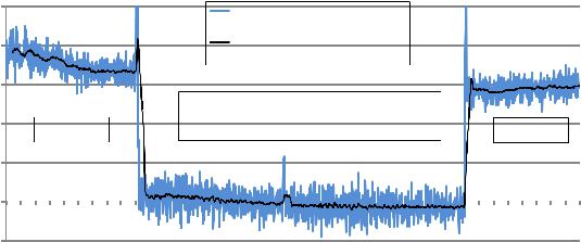
The ‘spot loading effect’ is a variable phenomenon which appears as a gradual reduction of instrumental response as the aerosol deposit density of the filter tape increases from zero to the predetermined limit of ‘Maximum Attenuation’ (Gundel 1984, Weingartner 2003, Arnott 2005, Virkkula 2007, Kanaya 2008). When the filter tape advances to a fresh spot, the data undergoes a discontinuous jump from its previous lower value, calculated when the spot was heavily loaded; to a higher value, calculated from collection on a fresh spot at zero loading. In the Aethalometer the reduction of data at increasing loadings is well described by a linear function of attenuation, but its magnitude cannot be predicted: some aerosols in some locations in some seasons may show a small or zero ‘loading effect’; while under other conditions, the effect may be larger and noticeable. Empirically, it is found that fresher aerosols closer to their combustion sources will show a larger ‘spot loading effect’; while well aged aerosols under atmospheric conditions of high chemical activity and oxidative processing may show an almost zero effect. The effect is revealed statistically by processing data collected over a large number of tape advances, representing many data points collected at loadings (‘ATN values’) ranging from zero to the preset maximum. The data is collected into bins according to loading (attenuation, ATN). If there is a systematic reduction of the calculated result as a function of loading, the data will show a clear negative slope, with the intercept representing the ‘zero loading’ value. Figure 2 illustrates two datasets from urban locations with loading effects either present or not.
07645A DCN6170 |
7 |

Model 633 Aethalometer® Black Carbon Monitor User Manual |
Teledyne Advanced Pollution Instrumentation |
Figure 2. Aethalometer data sorted and averaged according to loading (attenuation, ATN) on spot – roadside location in London, UK (top); urban site in Boston (Roxbury), USA (bottom).
The London data show a systematic reduction at increasing loadings; while the Boston data do not. This demonstrates that any method intended to compensate for the ‘spot loading effect’ must be auto adaptive and able to adjust dynamically to different situations. An instrument based on firmware with a fixed ‘loading non linearity’ parameter will not operate correctly at all locations. The ‘loading non linearity’ parameter must be measured.
8 |
07645A DCN6170 |
Teledyne Advanced Pollution Instrumentation |
Model 633 Aethalometer® Black Carbon Monitor User Manual |
It is clear that the effect, when present, is linear with loading (‘ATN’). This can be represented as:
BC (reported) = BC (zero loading) * { 1 k • ATN }
where BC (zero loading) is the desired ambient BC value that would be obtained in the absence of any loading effect; and k is the ‘loading compensation parameter’ (similar to Virkkula, 2007).
The analysis of a large number of datasets from a wide variety of locations shows that this relationship is linear in all cases studied; but with different values of k. It is therefore possible to eliminate the ‘loading effect’ of k by making two simultaneous identical measurements BC1 and BC2 at different degrees of loading ATN1 and ATN2.
BC1 = BC * { 1 k • ATN1 }
BC2 = BC * { 1 k • ATN2 }
From these two linear equations we may calculate the ‘loading compensation parameter’ k; and the desired value of BC compensated back to zero loading.
The Model 633 Aethalometer analyzes the Black Carbon component of aerosols on two parallel spots drawn from the same input stream, but collected at different rates of accumulation, i.e. at different values of ATN. By combining the data according to the above equations, the Model 633 yields the value of BC extrapolated back to ‘zero loading’; as well as a real time output of the ‘loading compensation parameter’ k which provides insights into the aerosol nature and composition. This process is performed in real time for all wavelengths: examination of the ‘k’ values as a function of wavelength provides further information about the aerosol composition. An example of this is shown for extreme concentrations of black carbon (Figure 3).
07645A DCN6170 |
9 |

Model 633 Aethalometer® Black Carbon Monitor User Manual |
Teledyne Advanced Pollution Instrumentation |
|
|
IR, 1 second |
|
|
|
|
raw BC1 |
|
80000 |
|
raw BC2 |
|
|
compensated BC |
|
|
|
|
|
) |
|
|
|
3 |
|
|
|
(ng/m |
60000 |
|
|
|
|
|
|
concentration |
40000 |
|
|
20000 |
|
|
|
BC |
|
|
|
|
|
|
|
|
0 |
|
|
|
2000 |
3000 |
4000 |
time (sec)
Figure 3. The timeseries of 633 raw and compensated BC concentrations with 1 second timebase – note the extreme concentrations and loading effects.
1.1.2 Automatic Zero and Span
The Model 633 Aethalometer is capable of automatically checking the ‘zero air’ response of the instrument under dynamic operating conditions. This test is implemented by back flushing the inlet connection with an excess flow of internally filtered air and circulating the filtered air in the instrument. The data reported during this period are analyzed for the mean value and the point to point variation. The mean value should be close to zero under ideal conditions; any positive value greater than zero represents the leakage of BC containing room air into the instrument’s analytical zone. The point to point variation represents the instrument’s measurement noise level under actual operating conditions of actual flow – i.e., a ‘dynamic’ test. The point to point variation for the wavelength 370 nm at the time base set to one second is about 125 ng/m3, which translates to a couple of ng/m3 at 1 minute time resolution (Figure 4).
10 |
07645A DCN6170 |
Teledyne Advanced Pollution Instrumentation |
Model 633 Aethalometer® Black Carbon Monitor User Manual |
2500 |
|
|
|
|
|
|
|
|
|
|
|
|
|
|
|
|
|
|
1 second time-base |
|
|
|
|
|
|
|
|
||
2000 |
|
|
|
|
30 per. Mov. Avg. (1 second time- |
|
|
|
|
|
|
|
||
|
|
|
|
|
base) |
|
|
|
|
|
|
|
|
|
1500 |
|
|
|
|
|
|
|
|
|
|
|
|
|
|
|
|
|
|
Point-to-point variation @ 1 second: |
|
|
|
|
|
|
|
|||
1000 |
|
|
|
|
|
126 ng/m3 |
|
|
|
|
|
|
||
|
131 ng/m3 |
|
|
|
|
|
|
|
119 ng/m3 |
|
||||
500 |
|
|
|
|
|
|
|
|
|
|
|
|
|
|
0 |
|
|
|
|
|
|
|
|
|
|
|
|
|
|
|
14:35:00 |
14:40:00 |
14:45:00 |
14:50:00 |
14:55:00 |
15:00:00 |
15:05:00 |
15:10:00 |
||||||
14:30:00 |
||||||||||||||
-500
Figure 4. ‘Zeroair’ check – the Model 633 Aethalometer switches from sampling ambient air to filtered air – 1 second time resolution pointtopoint variation is very stable.
The response of the optical detectors of the Model 633 Aethalometer may be verified using a standard kit of Neutral Density optical filters. These are glass elements with a range of known and stable optical absorptions, from light to dark, which are traceable from manufacturing records back to primary standards. When these are inserted into the Model 633 Aethalometer, its photodetectors will give a certain output signal. The stability and reproducibility of the relationship between optical signal and ND Filter density from one validation test to another; and the comparison with the original factory values; is a measure of the consistency of performance of the instrument’s optics.
1.1.3 User and Communications Interfaces
The Model 633 Aethalometer incorporates the following user, data and communications features:
•21 cm (8.25”) color graphics touch screen for data display and local user interface;
•USB ports for insertion of a memory stick for local data download;
•USB ports for connection of a keyboard, if necessary for initial setup of parameters, such as station identification;
•RS 232 COM ports for data transmission from auxiliary instruments or to the digital datalogger;
(Ethernet port installed for future software implementation).
07645A DCN6170 |
11 |
Model 633 Aethalometer® Black Carbon Monitor User Manual |
Teledyne Advanced Pollution Instrumentation |
1.1.4 Modular Construction
The Model 633 Aethalometer is constructed with a modular design, so that sub units may be easily serviced. The only item requiring attention in routine use is cleaning of the optical insert to remove accumulated dust or other contamination which may be brought in with the sample air stream. The optical chamber is attached with a bayonet fitting for quick removal; easy cleaning; and reliable re assembly. The entire instrument is hermetically sealed to reduce the entry of dust.
12 |
07645A DCN6170 |

Teledyne Advanced Pollution Instrumentation |
Model 633 Aethalometer® Black Carbon Monitor User Manual |
1.2 Technical Specifications
Operation:
Supply voltage: 100 240 V~, 50/60 Hz
Max power consumption: 90W
Measurement wavelengths: 370, 470, 525, 590, 660, 880 and 940 nm
Air flow: adjustable 2, 3, 4 and 5 LPM
Environmental operating conditions:
Indoor use
Altitude: up to 3000 m with internal pump, other configurations possible
Temperature range: 10 – 40 degrees Celsius (instrument)
Relative humidity range: non condensing
Mechanical specification:
Chassis material: sheet metal
Front plate material: plastic
Dimensions: standard 19”/6U, rack mount
Weight: approx. 20 kg
Connectors:
Sampling air: inlet / outlet type – ¼” NTPF
Communication: 3x USB type A, 3x RS 232 COM, 1x Ethernet
User interface:
8.4” SVGA display with LED backlight
Basic control: touch screen
Optional control: standard PC keyboard and mouse
Red, Yellow, Red status LEDs
Data storage capacity: 10+ years, at 1 minute intervals
07645A DCN6170 |
13 |
Model 633 Aethalometer® Black Carbon Monitor User Manual |
Teledyne Advanced Pollution Instrumentation |
1.3 Functional Description
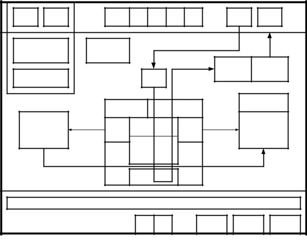
The Model 633 features modular design and is composed of several subsystems which are so interconnected that most simple and safe handling of the instrument is possible. Presented here are a functional block diagram followed by a flow diagram.
Figure 5. Model 633 functional block diagram
14 |
07645A DCN6170 |
Teledyne Advanced Pollution Instrumentation |
Model 633 Aethalometer® Black Carbon Monitor User Manual |
ENCLOSURE
The Model 633 enclosure is very robust and made from sheet metal. The enclosure mechanically protects the delicate inner measurement parts. The dimensions of the enclosure meet the rack mount standard for the instrumentation.
POWER SUPPLY
The power supply module is composed of the mains inlet, the power supply electronics and the cooling fan. Since the power supply electronics heats up, it is mechanically integrated in a separated and thermally sealed area.
MAINS INLET
The mains inlet accepts standard EU, US or UK supply cords. It is composed of the inlet itself, the EMC filter, the main fuse and the primary ON/OFF switch. The switch is a part of the power supply module.
COOLING FAN
The cooling fan is also a part of the power supply module. The control electronics measures the temperature of the power supply area and switches on and off the cooling fan.
MAIN COMPUTER
The main computer processor also generates quite a lot of heat. It is integrated in the power supply area so it can be cooled down together with the power supply electronics. The highest level control software and the user interface are implemented on the main, PC based computer.
ELECTRONIC BOARDS
The system features modular design so the electronics is composed of various electronics boards which mechanically fit together with other mechanical modules. The low level control firmware is implemented with microcontrollers, which are located on separate electronic boards so parallel real time data processing is possible.
07645A DCN6170 |
15 |
Model 633 Aethalometer® Black Carbon Monitor User Manual |
Teledyne Advanced Pollution Instrumentation |
ETHERNET CONNECTOR
The Ethernet connector allows the connection of the Model 633 measurement system to Ethernet based communication networks.
COM1, COM2, COM3 CONNECTORS
The COM connectors allow the connection of the system to RS232 based devices, like external sensors or dataloggers.
USB CONNECTOR (rear panel)
The USB connector allows the connection of the system to USB based devices, like external sensors or data processing units.
AIR INLET and OUTLET CONNECTORS
The air inlet and outlet connector allows the connection of the instrument to external airflow system. The measured air enters the instrument through the inlet connector and leaves the instrument through the outlet connector.
BALL VALVE
The ball valve is an electrically actuated valve which is connected directly to the inlet connector and connects or separates the instrument from the external air system.
CRC
The CRC (also called muffler) is a filter used to decrease the noise in the airflow which is created by mechanical rotation of the pump.
AIR PUMP
The air pump pumps the measured air through the inlet connector, directly to the measurement chamber. It is one of the main components in the system.
16 |
07645A DCN6170 |
Teledyne Advanced Pollution Instrumentation |
Model 633 Aethalometer® Black Carbon Monitor User Manual |
FLOWMETERS
Two flow meters measure the airflow in different points in the system. One of them is used also in the air flow regulation loop.
SOLENOID VALVES
Three solenoid valves are used to switch the airflow through different airflow paths when the instrument is set in different operating modes like measure, tape advance or similar.
CHAMBER LIFT MECHANISM
The chamber lift mechanism allows the measurement chamber to be lifted manually or electromechanically. During tape advance the automated chamber lift procedure is invoked. During tape replacement the manual chamber lift procedure can be engaged. The manual chamber lift mechanism features also a special locking mechanism which simplifies the tape replacement or chamber cleaning procedure. The main electronic components of the chamber lift mechanism are the stepper motor and the chamber lift position sensor.
TAPE ADVANCE MECHANISM
The advance mechanism allows the instrument to perform automatic tape advances during measurements. The main electronic parts of the tape advance mechanism are a stepper motor and the two tape sensors.
ROLLON and UNROLL TAPE SPOOLS
The roll on and the un roll tape spools hold the measurement tape. During automated tape advance the tape unrolls from the un roll spool and rolls on the roll on spool. If the un roll spool is empty, the event is detected automatically thanks to the tape sensors. The tape replacement procedure must be performed manually by the operator. The measurement tape is one of the main parts of the system.
TAPE SENSORS
The two tape sensors are used by the instrument software to detect the amount of tape on the un roll and roll on spools.
07645A DCN6170 |
17 |
Model 633 Aethalometer® Black Carbon Monitor User Manual |
Teledyne Advanced Pollution Instrumentation |
LIGHT SOURCE
The light source integrates groups of LEDs of different light wavelengths. It is one of the main parts of the system.
DETECTOR
The detector detects what amount of light passes through the measurement tape. A special algorithm is used to calculate the black carbon concentration using the information from the detector and the flow meter.
FRONT PANEL DOOR
The front panel door can be opened which allows the access to the instrument for tape replacement or chamber cleaning.
DISPLAY and TOUCHSCREEN
The display and the touch screen are the main user interfaces of the instrument. Using this interface the operator can perform all necessary operations for proper functioning of the instrument.
USB CONNECTORS (front panel)
The two USB ports on the front panel door can be used to connect a keyboard, mouse or a USB key for data download or data upload.
STATUS LEDS
The red, yellow and green status LEDs show the correct or incorrect operation of the instrument. This status is replicated on the screen with the Status Condition (see, 4.2 Instrument Status).
DOOR KNOB
The door knob is used to open the front panel door.
18 |
07645A DCN6170 |
Teledyne Advanced Pollution Instrumentation |
Model 633 Aethalometer® Black Carbon Monitor User Manual |
ON/OFF SWITCH
The secondary ON/OFF switch is located behind the front door. It is electrically connected in series with the primary ON/OFF switch, which is located at the back of the instrument, next to the mains inlet. (Both switches must be set to ON to power up the instrument, but either one can be set to OFF to power down the instrument).
07645A DCN6170 |
19 |
Model 633 Aethalometer® Black Carbon Monitor User Manual |
Teledyne Advanced Pollution Instrumentation |
This page intentionally left blank.
20 |
07645A DCN6170 |
2 SAFETY NOTES and LABELS
CAUTION!
READ THIS CHAPTER VERY CAREFULLY BEFORE OPERATING THE INSTRUMENT.
Instrument operation
Read this User’s manual BEFORE operating the instrument. INCORRECT instrument operation can be DANGEROUS for the operator.
Unauthorised instrument access and operation
The instrument must be protected against unqualified use. UNAUTHORISED instrument access and operation can be dangerous. The instrument can only be operated by persons who can ensure proper handling due to their qualification, technical skills and practical experience.
Electric shock
CHECK the mains power supply cord ANNUALLY. If the supply cable is DAMAGED, stop using the equipment and contact your authorized representative.
07645A DCN6170 |
21 |
Loading...