


OPERATING INSTRUCTIONS FOR
Model 3290
Percent Oxygen Analyzer
P/N M64643
8/10/11
DANGER
Depending upon your application, toxic gases may be present in this monitoring system.
Personal protective equipment may be required when servicing this instrument.
Hazardous voltages exist on certain components internally which may persist for a time even after the power is turned off and disconnected.
Only authorized personnel should conduct maintenance and/or servicing. Before conducting any maintenance or servicing, consult with authorized supervisor/manager.
 Teledyne Analytical Instruments

Model 3290
Copyright © 2011 Teledyne Instruments/ Analytical Instruments
All Rights Reserved. No part of this manual may be reproduced, transmitted, transcribed, stored in a retrieval system, or translated into any other language or computer language in whole or in part, in any form or by any means, whether it be electronic, mechanical, magnetic, optical, manual, or otherwise, without the prior written consent of Teledyne Instruments/ Analytical Instruments, 16830 Chestnut Street, City of Industry, CA 917491580.
Warranty
This equipment is sold subject to the mutual agreement that it is warranted by us free from defects of material and of construction, and that our liability shall be limited to replacing or repairing at our factory (without charge, except for transportation), or at customer plant at our option, any material or construction in which defects become apparent within one year from the date of shipment, except in cases where quotations or acknowledgements provide for a shorter period. Components manufactured by others bear the warranty of their manufacturer. This warranty does not cover defects caused by wear, accident, misuse, neglect or repairs other than those performed by TI/AI or an authorized service center. We assume no liability for direct or indirect damages of any kind and the purchaser by the acceptance of the equipment will assume all liability for any damage which may result from its use or misuse.
We reserve the right to employ any suitable material in the manufacture of our apparatus, and to make any alterations in the dimensions, shape or weight of any parts, in so far as such alterations do not adversely affect our warranty.
Important Notice
This instrument provides measurement readings to its user, and serves as a tool by which valuable data can be gathered. The information provided by the instrument may assist the user in eliminating potential hazards caused by his process; however, it is essential that all personnel involved in the use of the instrument or its interface, with the process being measured, be properly trained in the process itself, as well as all instrumentation related to it.
The safety of personnel is ultimately the responsibility of those who control process conditions. While this instrument may be able to provide early warning of imminent danger, it has no control over process conditions, and it can be misused. In particular, any alarm or control systems installed must be tested and understood, both as to how they operate and as to how they can be defeated. Any safeguards required such as locks, labels, or redundancy, must be provided by the user or specifically requested of TI/AI at the time the order is placed.
Therefore, the purchaser must be aware of the hazardous process conditions. The purchaser is responsible for the training of personnel, for providing hazard warning methods and instrumentation per the appropriate standards, and for ensuring that hazard warning devices and instrumentation are maintained and operated properly.
Teledyne Instruments/Analytical Instruments, the manufacturer of this instrument, cannot accept responsibility for conditions beyond its knowledge and control. No statement expressed or implied by this document or any information disseminated by the manufacturer or its agents, is to be construed as a warranty of adequate safety control under the user’s process conditions.
Teledyne Analytical Instruments |
ii |

Percent Oxygen Analyzer
Specific Model Information
Instrument Serial Number: _______________________
Instrument Range: |
_______________ |
Background Gas: |
_______________ |
Span Gas: |
_______________ |
Teledyne Analytical Instruments |
iii |
Model 3290
Safety Messages
Your safety and the safety of others is very important. We have provided many important safety messages in this manual. Please read these messages carefully.
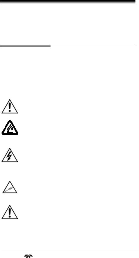
A safety message alerts you to potential hazards that could hurt you or others. Each safety message is associated with a safety alert symbol. These symbols are found in the manual and inside the instrument. The definition of these symbols is described below:
GENERAL WARNING/CAUTION: Refer to the instructions for details on the specific danger. These cautions warn of specific procedures which if not followed could cause bodily Injury and/or damage the instrument.
WARNING: HOT SURFACE WARNING: This warning is
specific to heated components within the instrument. Failure to heed the warning could result in serious burns to skin and underlying tissue.
WARNING: ELECTRICAL SHOCK HAZARD: Dangerous
voltages appear within this instrument. This warning is specific to an electrical hazard existing at or nearby the component or procedure under discussion. Failure to heed this warning could result in injury and/or death from electrocution.
Technician Symbol: All operations marked with this symbol are to be performed by qualified maintenance personnel only.
CAUTION: THE ANALYZER SHOULD ONLY BE USED FOR THE PURPOSE AND IN THE MANNER DESCRIBED IN THIS MANUAL.
IF YOU USE THE ANALYZER IN A MANNER OTHER THAN THAT FOR WHICH IT WAS INTENDED, UNPREDICTABLE BEHAVIOR COULD RESULT POSSIBLY ACCOMPANIED WITH HAZARDOUS CONSEQUENCES.
Teledyne Analytical Instruments |
iv |

Percent Oxygen Analyzer
This manual provides information designed to guide you through the installation, calibration operation and maintenance of your new analyzer. Please read this manual and keep it available.
Occasionally, some instruments are customized for a particular application or features and/or options added per customer requests. Please check the front of this manual for any additional information in the form of an Addendum which discusses specific information, procedures, cautions and warnings that may be peculiar to your instrument.
Manuals do get lost. Additional manuals can be obtained from TI/AI at the address given in the Appendix. Some of our manuals are available in electronic form via the internet. Please visit our website at: www.teledyne-ai.com.
Teledyne Analytical Instruments |
v |

Model 3290
Table of Contents |
|
|
List of Figures ............................................................................ |
viii |
|
List of Tables ................................................................................ |
ix |
|
Introduction ................................................................................... |
1 |
|
1.1 |
Overview |
1 |
1.2 |
Main Features of the Analyzer |
1 |
1.3 |
Front Panel Description |
2 |
1.4 |
Rear Panel Description |
4 |
Operational Theory ....................................................................... |
7 |
|
2.1 |
Introduction |
7 |
2.2 |
Oxygen Sensor |
7 |
2.2.1 Principles of Operation |
7 |
|
2.2.2 Anatomy of the Oxygen Sensor |
8 |
|
2.2.3 Electrochemical Reactions |
9 |
|
2.2.4 The Effect of Pressure |
10 |
|
2.2.5 Calibration Characteristics |
11 |
|
2.3 |
Electronics |
12 |
2.3.1 General |
12 |
|
2.3.2 Signal Processing |
12 |
|
Installation ................................................................................... |
15 |
|
3.1 |
Unpacking the Analyzer |
16 |
3.2 |
Location and Mounting |
16 |
3.2.1 Control Unit Installation |
16 |
|
3.2.2 External Probe Installation |
16 |
|
3.2.3 Installing the Oxygen Sensor |
17 |
|
3.3 |
Electrical Connections |
17 |
3.4 |
Gas Connections |
21 |
|
Teledyne Analytical Instruments |
vi |

Percent Oxygen Analyzer
3.5 |
Installation Checklist |
22 |
Operation ..................................................................................... |
23 |
|
4.1 |
Introduction |
23 |
4.2 |
Using the Function and Data Entry Buttons |
24 |
4.3 |
Setting the Analysis Ranges |
24 |
4.3.1 HI Range |
25 |
|
4.3.2 LO Range |
25 |
|
4.4 |
Setting the Alarm Setpoints |
25 |
4.4.1 HI Alarm |
25 |
|
4.4.2 LO Alarm |
26 |
|
4.4.3 Sensor Fail Alarm |
26 |
|
4.5 |
Selecting a Fixed Range or Autoranging |
26 |
4.6 |
Calibration |
26 |
Maintenance................................................................................. |
29 |
|
5.1 |
Replacing the Fuse |
29 |
5.1.1 AC Powered Units |
29 |
|
5.1.2 DC Powered Units |
30 |
|
5.2 |
Sensor Installation or Replacement |
30 |
5.2.1 When to Replace a Sensor |
30 |
|
5.2.2 Ordering and Handling of Spare Sensors |
31 |
|
5.2.3 Removing the Oxygen Sensor |
32 |
|
5.2.4 Installing the Oxygen Sensor |
32 |
|
5.2.5 Cell Warranty Conditions |
33 |
|
Appendix ...................................................................................... |
35 |
|
A.1 Specifications |
35 |
|
A.2 Spare Parts List (Standard Version) |
36 |
|
A.3 Drawing List (Standard Version) |
37 |
|
A.4 Miscellaneous |
37 |
|
Teledyne Analytical Instruments |
vii |

Model 3290
List of Figures
Figure 1-1: Front Panel ................................................................... |
2 |
Figure 1-2: Rear Panel (AC and DC versions) ................................ |
4 |
Figure 2-1: Basic Elements of the Oxygen Sensor (not to scale) .... |
8 |
Figure 2-2: Input/Output Curve for a Typical Oxygen Sensor........ |
11 |
Figure 2-3: Block Diagram of the Signal Processing Electronics... |
13 |
Figure 3-1: Rear Panel Electrical Connectors for AC & DC Units . 18 |
|
Figure 3-2: Contact Identification for FAILSAFE Relay Operation. 20 |
|
Figure 4-1: Front Panel Controls and Indicators............................ |
23 |
Figure 5-1: AC Fuse Replacement................................................ |
29 |
Teledyne Analytical Instruments |
viii |

Percent Oxygen Analyzer
List of Tables
Table 3-1: Required RS-232 Data Format..................................... |
21 |
Teledyne Analytical Instruments |
ix |

Model 3290
DANGER
COMBUSTIBLE GAS USAGE
WARNING
This is a general purpose instrument designed for use in a non-hazardous area. It is the customer's responsibility to ensure safety especially when combustible gases are being analyzed since the potential of gas leaks always exist.
The customer should ensure that the principles of operating this equipment are well understood by the user. Misuse of this product in any manner, tampering with its components, or unauthorized substitution of any component may adversely affect the safety of this instrument.
Since the use of this instrument is beyond the control of Teledyne Analytical Instruments, referred as TAI, no responsibility by TAI, its affiliates, and agents for damage or injury from misuse or neglect of this equipment is implied or assumed.
Teledyne Analytical Instruments |
x |
Percent Oxygen Analyzer |
Introduction |
|
|
|
|
|
|
|
Introduction
1.1 Overview
The Teledyne Analytical Instruments (TAI) Model 3290 is a microprocessor-based percent oxygen analyzer for real-time measurement of the percent of oxygen in inert gases, or in a wide variety of gas mixtures. It features simple operation, fast response, and a compact, rugged construction. Typical applications of the Model 3290 are monitoring nitrogen generators and inert gas blanketing applications.
1.2 Main Features of the Analyzer
The main features of the analyzer include:
High resolution, accurate readings of oxygen content from 0-1 % through 0-25 %. Large, bright, light-emitting-diode (LED) meter readout.
Simple pushbutton controls.
Nylon cell holder.
Advanced E-2 oxygen sensor for percent analysis, has a two-year warranty on the standard cell and an expected lifetime of four years.
Unaffected by oxidizable gases.
Fast response and recovery time.
Microprocessor based electronics: 8-bit CMOS microprocessor with on-board RAM and 16 KB ROM.
Two user selectable ranges (from 0-1 % through 0-25 %, optional 0-100%) allow best match to user’s process and equipment.
Air-calibration range for convenient spanning at 20.9 %.
Teledyne Analytical Instruments |
1 |
Introduction |
Model 3290 |
|
|
|
|
|
|
|
User selectable autoranging feature, which allows the analyzer to automatically select the proper preset range for a given measurement. The analyzer can also be manually locked on a fixed analysis range.
Two concentration alarms with adjustable setpoints.
Sensor failure alarm.
Optional RS-232 serial digital port for output of concentration and range data to a computer, terminal, or other digital device.
Three analog outputs: two for measurement (0–10 VDC, and negative ground 4–20 mA DC) and one for range identification (0-10 VDC).
Compact and rugged control unit with flush-panel case. Designed for indoor use. Front panel NEMA-4 rated.
External probe can be located 6 feet (1.83 meters) or more away, depending on the existing electromagnetic noise level.
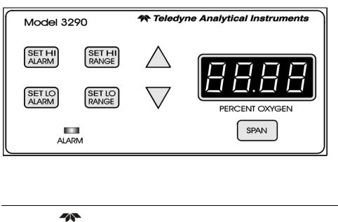
1.3Front Panel Description
All controls and displays except the power switch are accessible from the front panel. See Figure 1-1. The front panel has seven pushbutton membrane switches, a digital meter, and an alarm indicator LED for operating the analyzer. These features are described briefly here and in greater detail in Chapter 4, Operation.
Figure 1-1: Front Panel
Teledyne Analytical Instruments |
2 |

Percent Oxygen Analyzer |
Introduction |
|
|
|
|
|
|
|
Function Keys: Five pushbutton membrane switches are used to select the function performed by the analyzer:
Set HI Alarm Set the concentration ABOVE which
an alarm activates.
Set LO Alarm Set the concentration BELOW which
an alarm activates.
Set HI Range Set the high analysis range for the
instrument (up to 0-25 %).
Set LO Range Set the low analysis range for the
|
instrument (down to 0-1 %). |
Span |
Span calibrate the analyzer. |
Data Entry Keys: Two pushbutton membrane switches are used to manually change measurement parameters of the instrument as they are displayed on the LED meter readout:
Up Arrow Increment values of parameters
upwards as they are displayed on the LED readout.
Down Arrow Increment values of parameters
downwards as they are displayed on the LED readout.
Digital LED Readout: The digital display is a LED device that produces large, bright, 7-segment numbers that are legible in any lighting environment. It has two functions:
Meter Readout: As the meter readout, it displays the
oxygen concentration currently being measured.
Measurement Parameters Readout: It also displays
user-definable alarm setpoints, ranges, and span calibration point when they are being checked or changed.
Teledyne Analytical Instruments |
3 |

Introduction |
Model 3290 |
|
|
|
|
|
|
|
1.4 Rear Panel Description
The rear panel contains the electrical input and output connectors. Separate rear panel illustrations are shown in Figure 1-2 for the AC and DC powered versions of the instrument. The connectors are described briefly here and in detail in Chapter 3 Installation of this manual.
Figure 1-2: Rear Panel (AC and DC versions)
Teledyne Analytical Instruments |
4 |

Percent Oxygen Analyzer |
Introduction |
|
|
|
|
|
|
|
Power Connection AC version: 100–240 VAC, at 50/60
Hz. The connector housing includes the fuse holder and the power switch. DC version: Requires between 10 and 36 VDC.
Fuse Holder: Replacing the fuse is described in Chapter 5, Maintenance.
I/O Power Switch: Turns the instrument power ON (I) or OFF (O).
Analog Outputs 0–10 VDC concentration output.
0–10 VDC range ID (or optional overrange) output.
4–20 mA DC concentration output, negative ground.
Alarm Connections HI Alarm, LO Alarm, and Sensor
Failure Alarm connections.
RS-232 Port Serial digital output of concentration
(Option) |
and range signals. |
External Probe Connects to the Remote Probe or
remote Analysis Unit.
Teledyne Analytical Instruments |
5 |
 Loading...