


 Loading...
Operation Manual
Model T300/T300M
Carbon Monoxide Analyzer
Also supports operation of:
Models T320 and T320U Analyzers
(when used in conjunction with T320/320U Addendum, PN07406)
© TELEDYNE ADVANCED POLLUTION INSTRUMENTATION (TAPI)
9480 CARROLL PARK DRIVE
SAN DIEGO, CA 92121-5201
USA
Toll-free Phone: 800-324-5190
Phone: 858-657-9800
Fax: 858-657-9816
Email: api-sales@teledyne.com
Website: http://www.teledyne-api.com/
Copyright 2010-2012 |
06864B DCN6314 |
Teledyne Advanced Pollution Instrumentation |
14 February 2012 |
ABOUT TELEDYNE ADVANCED POLLUTION INSTRUMENTATION (TAPI)
Teledyne Advanced Pollution Instrumentation (TAPI), a business unit of Teledyne Instruments, Inc., is a worldwide market leader in the design and manufacture of precision analytical instrumentation used for air quality monitoring, continuous emissions monitoring, and specialty process monitoring applications. Founded in San Diego, California, in 1988, TAPI introduced a complete line of Air Quality Monitoring (AQM) instrumentation, which comply with the United States Environmental Protection Administration (EPA) and international requirements for the measurement of criteria pollutants, including CO, SO2, NOX and Ozone.
Since 1988 TAPI has combined state-of-the-art technology, proven measuring principles, stringent quality assurance systems and world class after-sales support to deliver the best products and customer satisfaction in the business.
For further information on our company, our complete range of products, and the applications that they serve , please visit www.teledyne-api.com or contact sales@teledyne-api.com.
NOTICE OF COPYRIGHT
© 2010-2012 Teledyne Advanced Pollution Instrumentation, Inc. All rights reserved.
TRADEMARKS
All trademarks, registered trademarks, brand names or product names appearing in this document are the property of their respective owners and are used herein for identification purposes only.
06864B DCN6314 |
i |

Teledyne API – Model T300/T300M CO Analyzer
This page intentionally left blank.
ii |
06864B DCN6314 |
IMPORTANT SAFETY INFORMATION
Important safety messages are provided throughout this manual. Please read these messages carefully.
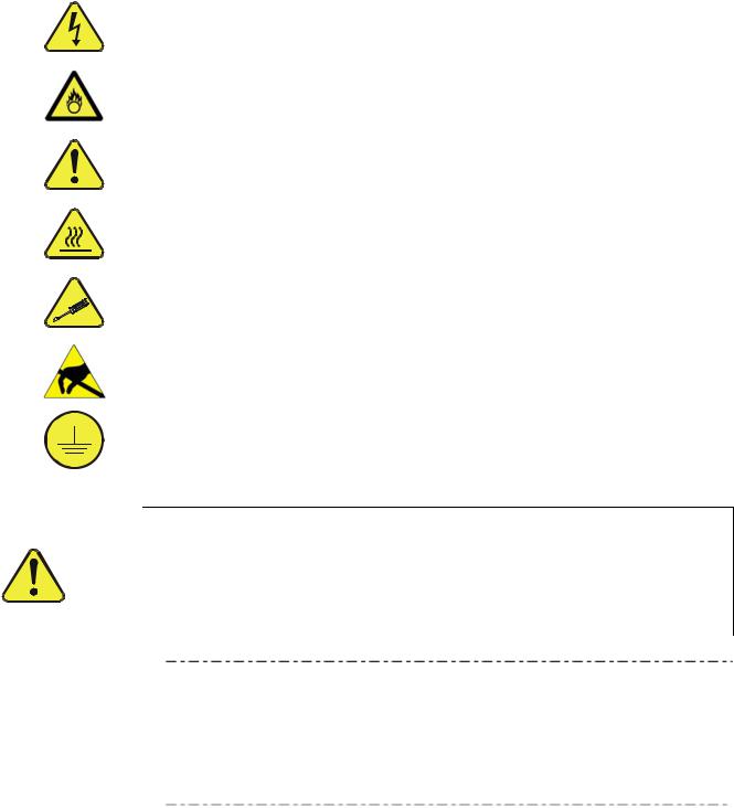
A safety message alerts you to potential hazards that could hurt you or others. Each safety message is associated with a safety alert symbol. These symbols are found in the manual and inside the instrument. The definition of these symbols is described below:
WARNING: Electrical Shock Hazard
HAZARD: Strong oxidizer
GENERAL WARNING/CAUTION: Read the accompanying message for specific information.
CAUTION: Hot Surface Warning
Technician Symbol: All operations marked with this symbol are to be performed by qualified maintenance personnel only.
DO NOT TOUCH: Touching some parts of the instrument without protection or proper tools could result in damage to the part(s) and/or the instrument.
Electrical Ground: This symbol inside the instrument marks the central safety grounding point for the instrument.
|
CAUTION - General Safety Hazard |
|
|
This instrument should only be used for the purpose and in the manner |
|
|
described in this manual. If you use this instrument in a manner other |
|
|
than that for which it was intended, unpredictable behavior could ensue |
|
|
with possible hazardous consequences. |
|
|
NEVER use any gas analyzer to sample combustible gas(es). |
|
Note |
Technical Assistance regarding the use and maintenance of the |
|
T300/T300M or any other Teledyne API product can be obtained by |
||
|
||
|
contacting Teledyne API’s Customer Service Department: |
|
|
Phone: 800-324-5190 |
|
|
Email: api-customerservice@teledyne.com |
|
|
or by accessing various service options on our website at |
|
|
7http://www.teledyne-api.com/. |
06864B DCN6314 |
iii |

Teledyne API – Model T300/T300M CO Analyzer
CONSIGNES DE SÉCURITÉ
Des consignes de sécurité importantes sont fournies tout au long du présent manuel dans le but d’éviter des blessures corporelles ou d’endommager les instruments. Veuillez lire attentivement ces consignes. Chaque consigne de sécurité est représentée par un pictogramme d’alerte de sécurité; ces pictogrammes se retrouvent dans ce manuel et à l’intérieur des instruments. Les symboles correspondent aux consignes suivantes :
AVERTISSEMENT : Risque de choc électrique
DANGER : Oxydant puissant
AVERTISSEMENT GÉNÉRAL / MISE EN GARDE : Lire la consigne complémentaire pour des renseignements spécifiques
MISE EN GARDE : Surface chaude
Ne pas toucher : Toucher à certaines parties de l’instrument sans protection ou sans les outils appropriés pourrait entraîner des dommages aux pièces ou à l’instrument.
Pictogramme « technicien » : Toutes les opérations portant ce symbole doivent être effectuées uniquement par du personnel de maintenance qualifié.
Mise à la terre : Ce symbole à l’intérieur de l’instrument détermine le point central de la mise à la terre sécuritaire de l’instrument.
MISE EN GARDE
Cet instrument doit être utilisé aux fins décrites et de la manière décrite dans ce manuel. Si vous utilisez cet instrument d’une autre manière que celle pour laquelle il a été prévu, l’instrument pourrait se comporter de façon imprévisible et entraîner des conséquences dangereuses.
NE JAMAIS utiliser un analyseur de gaz pour échantillonner des gaz combustibles!
iv |
06864B DCN6314 |

WARRANTY
WARRANTY POLICY (02024D)
Teledyne Advanced Pollution Instrumentation (TAPI), a business unit of Teledyne Instruments, Inc., warrants its products as follows:
Prior to shipment, TAPI equipment is thoroughly inspected and tested. Should equipment failure occur, TAPI assures its customers that prompt service and support will be available.
COVERAGE
After the warranty period and throughout the equipment lifetime, TAPI stands ready to provide on-site or in-plant service at reasonable rates similar to those of other manufacturers in the industry. All maintenance and the first level of field troubleshooting are to be performed by the customer.
NON-TAPI MANUFACTURED EQUIPMENT
Equipment provided but not manufactured by TAPI is warranted and will be repaired to the extent and according to the current terms and conditions of the respective equipment manufacturer’s warranty.
GENERAL
During the warranty period, TAPI warrants each Product manufactured by TAPI to be free from defects in material and workmanship under normal use and service. Expendable parts are excluded.
If a Product fails to conform to its specifications within the warranty period, TAPI shall correct such defect by, in TAPI's discretion, repairing or replacing such defective Product or refunding the purchase price of such Product.
The warranties set forth in this section shall be of no force or effect with respect to any Product: (i) that has been altered or subjected to misuse, negligence or accident, or (ii) that has been used in any manner other than in accordance with the instruction provided by TAPI, or (iii) not properly maintained.
THE WARRANTIES SET FORTH IN THIS SECTION AND THE REMEDIES THEREFORE ARE EXCLUSIVE AND IN LIEU OF ANY IMPLIED WARRANTIES OF MERCHANTABILITY, FITNESS FOR PARTICULAR PURPOSE OR OTHER WARRANTY OF QUALITY, WHETHER EXPRESSED OR IMPLIED. THE REMEDIES SET FORTH IN THIS SECTION ARE THE EXCLUSIVE REMEDIES FOR BREACH OF ANY WARRANTY CONTAINED HEREIN. API SHALL NOT BE LIABLE FOR ANY INCIDENTAL OR CONSEQUENTIAL DAMAGES ARISING OUT OF OR RELATED TO THIS AGREEMENT OF TAPI'S PERFORMANCE HEREUNDER, WHETHER FOR BREACH OF WARRANTY OR OTHERWISE.
TERMS AND CONDITIONS
All units or components returned to Teledyne API should be properly packed for handling and returned freight prepaid to the nearest designated Service Center. After the repair, the equipment will be returned, freight prepaid.
ATTENTION |
AVOID WARRANTY INVALIDATION |
|
Failure to comply with proper anti-Electro-Static Discharge (ESD) |
|
handling and packing instructions and Return Merchandise Authorization |
|
(RMA) procedures when returning parts for repair or calibration may void |
|
your warranty. For anti-ESD handling and packing instructions please |
|
refer to “Packing Components for Return to Teledyne API’s Customer |
|
Service” in the Primer on Electro-Static Discharge section of this manual, |
|
and for RMA procedures please refer to our Website at http://www.teledyne- |
|
api.com under Customer Support > Return Authorization. |
|
|
06864B DCN6314 |
v |

Teledyne API – Model T300/T300M CO Analyzer
This page intentionally left blank.
vi |
06864B DCN6314 |

ABOUT THIS MANUAL
Presented here is information regarding the documents that are included with this manual (Structure), its history of release and revisions (Revision History), how the content is organized (Organization), a description of other information related to this manual (Related Information), and the conventions used to present the information in this manual (Conventions Used).
STRUCTURE
This T300 manual, PN 06864, is comprised of multiple documents, assembled in PDF format, as listed below.
Part No. |
Rev |
Name/Description |
06864 |
B |
Operation Manual, T300 Carbon Monoxide Analyzer |
|
|
|
04906 |
H |
Appendix A, Menu Trees and related software documentation |
06849 |
A |
Spare Parts List (in Appendix B of this manual) |
04301 |
E |
Recommended Spares Stocking Levels List/T300 (in Appendix B of this manual) |
|
|
|
04834 |
G |
Recommended Spares Stocking Levels List/T300M (in Appendix B of this manual) |
04305 |
G |
Appendix C, Repair Form |
06912 |
B |
Interconnect Diagram (in Appendix D of this manual) |
069120100 |
B |
Interconnect Table (in Appendix D of this manual) |
|
|
Schematics (in Appendix Dof this manual) |
|
|
|
03297 |
K |
PCA, 03296, IR Photodetector Preamp and Sync Demodulator |
03632 |
A |
PCA, 03631, 0-20mA driver |
04354 |
D |
PCA, 04003, Pressure/Flow Transducer Interface |
05033 |
A |
PCA, 05032, Opto-Interrupter |
04136 |
B |
PCA, 04135, Relay Board |
04468 |
B |
PCA, 04467, Analog Output Isolator |
05803 |
B |
SCH, PCA 05802, MOTHERBOARD, GEN-5 |
06698 |
D |
SCH, PCA 06670, INTRFC, LCD TCH SCRN, |
06882 |
B |
SCH, LVDS TRANSMITTER BOARD |
06731 |
B |
SCH, AUX-I/O BOARD |
|
|
|
Note |
We recommend that this manual be read in its entirety before any attempt |
|
is made to operate the instrument. |
06864B DCN6314 |
vii |

Teledyne API – Model T300/T300M CO Analyzer
|
ORGANIZATION |
|
This manual is divided among three main parts and a collection of appendices at the end. |
|
Part I contains introductory information that includes an overview of the analyzer, |
|
descriptions of the available options, specifications, installation and connection |
|
instructions, and the initial calibration and functional checks. The last two sections |
|
contain Frequently Asked Questions (FAQs) followed by a glossary, and a description |
|
of available options. |
|
Part II comprises the operating instructions, which include basic, advanced and remote |
|
operation, calibration, diagnostics, testing, validating and verifying, and ends with |
|
specifics of calibrating for use in EPA monitoring. |
|
Part III provides detailed technical information, such as theory of operation, |
|
maintenance, and troubleshooting and repair. It also contains a section that provides |
|
important information about electro-static discharge and avoiding its consequences. |
|
The appendices at the end of this manual provide support information such as, version- |
|
specific software documentation, lists of spare parts and recommended stocking levels, |
|
and schematics. |
|
CONVENTIONS USED |
|
In addition to the safety symbols as presented in the Important Safety Information page, |
|
this manual provides special notices related to the safety and effective use of the |
|
analyzer and other pertinent information. |
|
Special Notices appear as follows: |
ATTENTION |
COULD DAMAGE INSTRUMENT AND VOID WARRANTY |
|
This special notice provides information to avoid damage to your |
|
instrument and possibly invalidate the warranty. |
IMPORTANT |
IMPACT ON READINGS OR DATA |
|
Could either affect accuracy of instrument readings or cause loss of data. |
Note |
Pertinent information associated with the proper care, operation or |
|
maintenance of the analyzer or its parts. |
viii |
06864B DCN6314 |
REVISION HISTORY
This section provides information regarding changes to this manual.
2012, February 14, T300/300M Manual, PN06864 Rev B
Document |
PN |
Rev |
DCN |
Change Summary |
Top Assy Manual |
06864 |
B |
6314 |
Administrative changes: restructure to new T-Series format: |
|
|
|
|
Consolidated Options sections and restructured into tabular |
|
|
|
|
format; moved to Section 1. |
|
|
|
|
Corrected Safety Compliance (was: IEC 61010-1:90 + A1:92 + |
|
|
|
|
A2:95; is: IEC 61010-1:2001). |
|
|
|
|
Added North American Certification statement. |
|
|
|
|
Section 2.1 – added 2nd gas sensor options specs. |
|
|
|
|
Replaced Fig 3-5 with correct internal layout illustration (was |
|
|
|
|
short box; is long box). |
|
|
|
|
Move pneumatic illustrations from Options section to |
|
|
|
|
pneumatic setup section. |
|
|
|
|
Gathered communications setup and operation into one group |
|
|
|
|
(Section 6). |
|
|
|
|
Renamed Part III from “Technical Information” to “Maintenance |
|
|
|
|
and Service”. |
|
|
|
|
Renamed “Troubleshooting and Repair” to “Troubleshooting |
|
|
|
|
and Service”. |
|
|
|
|
Renamed section “Theory of Operation” to “Principles of |
|
|
|
|
Operation”. |
|
|
|
|
Moved “Principles of Operation” section after “Maintenance” |
|
|
|
|
and “Troubleshooting and Service” sections. |
|
|
|
|
Moved FAQs to end of Troubleshooting/Service section |
|
|
|
|
Moved Glossary to end of manual before Index. |
|
|
|
|
Technical changes: |
|
|
|
|
Status Outputs: added connection line for +5V to external |
|
|
|
|
device (Fig 3-11) and corrected DC Power pin description |
|
|
|
|
(Table 3-6, deleted “combined rating w/Control Output if used”). |
|
|
|
|
Section 3.3.1.8: modify Multidrop connection section to clarify |
|
|
|
|
insructions and add detail. |
|
|
|
|
Correct COM1 default baud rate value to 115,200 (was: |
|
|
|
|
19,200) |
|
|
|
|
Added USB driver download instructions (Section 6.6) |
|
|
|
|
Replaced Appendix D Wiring List Rev A with Rev B. |
|
|
|
|
Replaced Appendix D Wiring Diagram Rev A with Rev B. |
|
|
|
|
Swapped Appendix D Prss/Flow Transducer was 04003 |
|
|
|
|
(assembly dwg) is 04354 (elec. schematic). |
|
|
|
|
Replaced Appendix D Schematic 06731 Rev A with Rev B. |
2010, September 14, T300 Manual, PN06864 Rev A, DCN 5840 Initial Release
06864B DCN6314 |
ix |

Teledyne API – Model T300/T300M CO Analyzer
This page intentionally left blank.
x |
06864B DCN6314 |

TABLE OF CONTENTS |
|
PART I GENERAL INFORMATION ....................................................................................... |
23 |
1. INTRODUCTION, FEATURES AND OPTIONS .................................................................. |
25 |
1.1. T300 Family Overview ................................................................................................................................. |
25 |
1.2. Features....................................................................................................................................................... |
26 |
1.3. T300/T300M Documentation ....................................................................................................................... |
26 |
1.4. Options......................................................................................................................................................... |
27 |
2. SPECIFICATIONS AND APPROVALS............................................................................... |
31 |
2.1. Specifications............................................................................................................................................... |
31 |
2.2. EPA Equivalency Designation ..................................................................................................................... |
33 |
2.3. Approvals and Certifications ........................................................................................................................ |
34 |
2.3.1. Safety ..................................................................................................................................................... |
34 |
2.3.2. EmC ....................................................................................................................................................... |
34 |
2.3.3. Other Type Certifications ....................................................................................................................... |
34 |
3. GETTING STARTED........................................................................................................... |
35 |
3.1. Unpacking the T300/T300M Analyzer ......................................................................................................... |
35 |
3.1.1. Ventilation Clearance............................................................................................................................. |
36 |
3.2. Instrument Layout ........................................................................................................................................ |
37 |
3.2.1. Front Panel ............................................................................................................................................ |
37 |
3.2.2. Rear panel ............................................................................................................................................. |
41 |
3.2.3. T300/T300M Analyzer Layout................................................................................................................ |
43 |
3.3. Connections and Setup................................................................................................................................ |
46 |
3.3.1. Electrical Connections ........................................................................................................................... |
46 |
3.3.1.1. Connecting Power .......................................................................................................................... |
46 |
3.3.1.2. Connecting Analog Inputs (Option) ................................................................................................ |
47 |
3.3.1.3. Connecting Analog Outputs ........................................................................................................... |
47 |
3.3.1.4. Current Loop Analog Outputs (Option 41) Setup .......................................................................... |
48 |
3.3.1.5. Connecting the Status Outputs ...................................................................................................... |
50 |
3.3.1.6. Connecting the Control Inputs........................................................................................................ |
51 |
3.3.1.7. Connecting the Concentration Alarm Relay (Option 61)................................................................ |
53 |
3.3.1.8. Connecting the Communication Interfaces .................................................................................... |
54 |
3.3.2. Pneumatic Connections ......................................................................................................................... |
61 |
3.3.2.1. Pneumatic Connections for Basic Configuration............................................................................ |
63 |
3.3.2.2. Pneumatic Layout for Basic configuration...................................................................................... |
65 |
3.3.2.3. Pneumatic Connections for Ambient Zero/Ambient Span Valve Option ........................................ |
65 |
3.3.2.4. Pneumatic Layout for Ambient Zero/Ambient Span Valve Option ................................................. |
67 |
3.3.2.5. Pneumatic Connections for Ambient Zero/Pressurized Span........................................................ |
67 |
3.3.2.6. Pneumatic Layout for Ambient Zero/Pressurized Span Option...................................................... |
69 |
3.3.2.7. Pneumatic Connections for Zero Scrubber/Pressurized Span Option........................................... |
70 |
3.3.2.8. Pneumatic Layout for Zero Scrubber/Pressurized Span Option .................................................... |
71 |
3.3.2.9. Pneumatic Connections for Zero Scrubber/Ambient Span Option................................................. |
72 |
3.3.2.10. Pneumatic Layout for Zero scrubber/ Ambient Span OPTion...................................................... |
74 |
3.3.2.11. Calibration Gases ......................................................................................................................... |
74 |
3.4. Startup, Functional Checks, and Initial Calibration...................................................................................... |
76 |
3.4.1. Startup.................................................................................................................................................... |
76 |
3.4.2. Warning Messages ................................................................................................................................ |
76 |
3.4.3. Functional Checks ................................................................................................................................. |
78 |
3.4.4. Initial Calibration .................................................................................................................................... |
79 |
3.4.4.1. Interferents for CO Measurements................................................................................................. |
80 |
3.4.4.2. Initial Calibration Procedure ........................................................................................................... |
80 |
3.4.4.3. O2 Sensor Calibration Procedure .................................................................................................. |
85 |
3.4.4.4. CO2 Sensor Calibration Procedure................................................................................................ |
85 |
06864B DCN6314 |
xi |

Table of Contents Teledyne API – Model T300/T300M CO Analyzer
PART II OPERATING INSTRUCTIONS.................................................................................. |
87 |
4. OVERVIEW OF OPERATING MODES ............................................................................... |
89 |
4.1. Sample Mode............................................................................................................................................... |
90 |
4.1.1. Test Functions ....................................................................................................................................... |
90 |
4.1.2. Warning Messages ................................................................................................................................ |
93 |
4.2. Calibration Mode.......................................................................................................................................... |
94 |
4.3. Setup MODE................................................................................................................................................ |
95 |
4.3.1. Password Security ................................................................................................................................. |
95 |
4.3.2. Primary Setup Menu .............................................................................................................................. |
95 |
4.3.3. The areas accessible under the Setup mode are shown in Table 4-4 and Secondary Setup Menu |
|
(SETUP>MORE).............................................................................................................................................. |
95 |
4.3.4. Secondary Setup Menu (SETUP>MORE)............................................................................................. |
96 |
5. SETUP MENU 97 |
|
5.1. SETUP CFG: Configuration Information ................................................................................................. |
97 |
5.2. SETUP ACAL: Automatic Calibration...................................................................................................... |
98 |
5.3. SETUP DAS: Internal Data Acquisition System....................................................................................... |
98 |
5.4. SETUP RNGE: Analog Output Reporting Range Configuration ............................................................. |
98 |
5.4.1. Analog Output Ranges for CO Concentration ....................................................................................... |
98 |
5.4.2. Physical Range vs Analog Output Reporting Ranges ........................................................................ |
100 |
5.4.3. Reporting Range Modes: Single, Dual, Auto Ranges ........................................................................ |
100 |
5.4.3.1. SINGLE Range Mode (SNGL) .................................................................................................... |
102 |
5.4.3.2. DUAL Range Mode (DUAL) ........................................................................................................ |
103 |
5.4.3.3. AUTO Range Mode (AUTO) ....................................................................................................... |
105 |
5.4.4. Range Units ........................................................................................................................................ |
107 |
5.4.5. Dilution Ratio (Option)......................................................................................................................... |
108 |
5.5. SETUP PASS: Password Protection.................................................................................................... |
109 |
5.6. SETUP CLK: Setting the Internal Time-of-Day Clock and Adjusting Speed........................................ |
111 |
5.6.1.1. Setting the Internal Clock’s Time and Day .................................................................................. |
111 |
5.6.1.2. Adjusting the Internal Clock’s Speed........................................................................................... |
111 |
5.7. SETUP Comm: Communications Ports ................................................................................................ |
113 |
5.7.1. ID (Machine Identification) .................................................................................................................. |
113 |
5.7.2. INET (Ethernet)................................................................................................................................... |
113 |
5.7.3. COM1 and COM2 (Mode, Baud Rate and Test Port)......................................................................... |
113 |
5.8. SETUP VARS: Variables Setup and Definition ..................................................................................... |
114 |
5.9. SETUP Diag: Diagnostics Functions..................................................................................................... |
116 |
5.9.1. Signal I/O ............................................................................................................................................ |
118 |
5.9.2. Analog Output ..................................................................................................................................... |
119 |
5.9.3. Analog I/O Configuration..................................................................................................................... |
120 |
5.9.3.1. Analog Output Voltage / Current Range Selection...................................................................... |
122 |
5.9.3.2. Analog Output Calibration ........................................................................................................... |
124 |
5.9.3.3. Enabling or Disabling the AutoCal for an Individual Analog Output............................................ |
124 |
5.9.3.4. Automatic Calibration of the Analog Outputs .............................................................................. |
126 |
5.9.3.5. Individual Calibration of the Analog Outputs ............................................................................... |
127 |
5.9.3.6. Manual Calibration of the Analog Outputs Configured for Voltage Ranges................................ |
128 |
5.9.3.7. Manual Adjustment of Current Loop Output Span and Offset .................................................... |
130 |
5.9.3.8. Turning an Analog Output Over-Range Feature ON/OFF .......................................................... |
133 |
5.9.3.9. Adding a Recorder Offset to an Analog Output........................................................................... |
134 |
5.9.3.10. AIN Calibration .......................................................................................................................... |
135 |
5.9.3.11. Analog Inputs (XIN1…XIN8) Option Configuration ................................................................... |
136 |
5.9.4. Electrical Test ..................................................................................................................................... |
137 |
5.9.5. Dark Calibration .................................................................................................................................. |
137 |
5.9.6. Pressure Calibration ........................................................................................................................... |
137 |
5.9.7. Flow Calibration .................................................................................................................................. |
138 |
5.9.8. Test Chan Output................................................................................................................................ |
138 |
5.9.8.1. Selecting a Test Channel Function for Output A4....................................................................... |
138 |
xii |
06864B DCN6314 |

Teledyne API – Model T300/T300M CO Analyzer |
Table of Contents |
|
5.10. SETUP MORE ALRM (Option): Using the Gas Concentration Alarms |
.......................................... |
140 |
5.10.1. Setting the T300 Concentration Alarm Limits ................................................................................... |
|
141 |
6. COMMUNICATIONS SETUP AND OPERATION ............................................................. |
|
143 |
6.1. Data Terminal/Communication Equipment (DTE DCE)............................................................................ |
|
143 |
6.2. Communication Modes, Baud Rate and Port Testing .................................................................................. |
|
143 |
6.2.1. Communication Modes ....................................................................................................................... |
|
144 |
6.2.2. COM Port Baud Rate .......................................................................................................................... |
|
146 |
6.2.3. Com Port Testing ................................................................................................................................ |
|
147 |
6.3. RS-232...................................................................................................................................................... |
|
147 |
6.4. RS-485 (Option)........................................................................................................................................ |
|
148 |
6.5. Ethernet..................................................................................................................................................... |
|
148 |
6.5.1. Configuring Ethernet Communication Manually (Static IP Address) .................................................. |
|
149 |
6.5.2. Configuring Ethernet Communication Using Dynamic Host Configuration ............Protocol (DHCP) |
151 |
|
6.5.3. Changing the Analyzer’s HOSTNAME ............................................................................................... |
|
152 |
6.6. USB Port (Option) for Remote Access ..................................................................................................... |
|
153 |
6.7. Communications Protocols ....................................................................................................................... |
|
155 |
6.7.1. MODBUS ............................................................................................................................................ |
|
155 |
6.7.2. Hessen................................................................................................................................................ |
|
156 |
6.7.2.1. Hessen COMM Port Configuration.............................................................................................. |
|
157 |
6.7.2.2. Activating Hessen Protocol ......................................................................................................... |
|
159 |
6.7.2.3. Selecting a Hessen Protocol Type .............................................................................................. |
|
160 |
6.7.2.4. Setting The Hessen Protocol Response Mode ........................................................................... |
|
161 |
6.7.3. Hessen Protocol Gas List Entries ....................................................................................................... |
|
162 |
6.7.3.1. Hessen Protocol Gas ID.............................................................................................................. |
|
162 |
6.7.3.2. Editing or Adding HESSEN Gas List Entries............................................................................... |
|
163 |
6.7.3.3. Deleting HESSEN Gas List Entries ............................................................................................. |
|
164 |
6.7.3.4. Setting Hessen Protocol Status Flags......................................................................................... |
|
165 |
6.7.3.5. Instrument ID ............................................................................................................................... |
|
166 |
7. DATA ACQUISITION SYSTEM (DAS) AND APICOM...................................................... |
|
167 |
7.1. DAS Structure ........................................................................................................................................... |
|
168 |
7.1.1. DAS Data Channels............................................................................................................................ |
|
169 |
7.1.2. Default DAS Channels ........................................................................................................................ |
|
169 |
7.1.3. Viewing DAS Channels and Individual Records................................................................................. |
|
172 |
7.1.4. Editing DAS Channels ........................................................................................................................ |
|
173 |
7.1.4.1. Editing DAS Data Channel Names.............................................................................................. |
|
174 |
7.1.5. Editing DAS Triggering Events ........................................................................................................... |
|
175 |
7.1.6. Editing DAS Parameters..................................................................................................................... |
|
176 |
7.1.7. Sample Period and Report Period ...................................................................................................... |
|
178 |
7.1.8. Number of Records............................................................................................................................. |
|
181 |
7.1.9. RS-232 Report Function ..................................................................................................................... |
|
183 |
7.1.9.1. The Compact Report Feature...................................................................................................... |
|
183 |
7.1.9.2. The Starting Date Feature........................................................................................................... |
|
184 |
7.1.10. Disabling/Enabling Data Channels ................................................................................................... |
|
184 |
7.1.11. HOLDOFF Feature ........................................................................................................................... |
|
185 |
7.2. Remote DAS Configuration....................................................................................................................... |
|
186 |
7.2.1. DAS Configuration via APICOM ......................................................................................................... |
|
186 |
7.2.2. DAS Configuration Using Terminal Emulation Programs ................................................................... |
|
188 |
8. REMOTE OPERATION ..................................................................................................... |
|
189 |
8.1. Computer Mode ........................................................................................................................................ |
|
189 |
8.1.1. Remote Control via APICOM.............................................................................................................. |
|
189 |
8.2. Interactive Mode ....................................................................................................................................... |
|
190 |
8.2.1. Remote Control via a Terminal Emulation Program ........................................................................... |
|
190 |
8.2.1.1. Help Commands in Interactive Mode .......................................................................................... |
|
190 |
8.2.1.2. Command Syntax ........................................................................................................................ |
|
190 |
8.2.1.3. Data Types .................................................................................................................................. |
|
191 |
06864B DCN6314 |
xiii |

Table of Contents |
Teledyne API – Model T300/T300M CO Analyzer |
|
8.2.1.4. Status Reporting.......................................................................................................................... |
|
192 |
8.2.1.5. General Message Format............................................................................................................ |
|
192 |
8.3. Remote Access by Modem....................................................................................................................... |
|
192 |
8.4. Password Security for Serial Remote Communications ........................................................................... |
|
195 |
9. CALIBRATION PROCEDURES........................................................................................ |
|
197 |
9.1. Calibration Preparations ........................................................................................................................... |
|
197 |
9.1.1. Required Equipment, Supplies, and Expendables ............................................................................. |
|
197 |
9.1.1.1. Zero Air........................................................................................................................................ |
|
198 |
9.1.1.2. Span Gas..................................................................................................................................... |
|
198 |
9.1.1.3. Calibration Gas Standards and Traceability................................................................................ |
|
198 |
9.1.2. Data Recording Devices ..................................................................................................................... |
|
199 |
9.2. Manual Calibration .................................................................................................................................... |
|
199 |
9.2.1. Setup for Basic Calibration Checks and Calibration........................................................................... |
|
200 |
9.2.2. Performing a Basic Manual Calibration Check ................................................................................... |
|
201 |
9.2.3. Performing a Basic Manual Calibration .............................................................................................. |
|
202 |
9.2.3.1. Setting the Expected Span Gas Concentration........................................................................... |
|
202 |
9.2.3.2. Zero/Span Point Calibration Procedure....................................................................................... |
|
204 |
9.3. Manual Calibration with Zero/Span Valves............................................................................................... |
|
205 |
9.3.1. Setup for Calibration Using Valve Options ......................................................................................... |
|
205 |
9.3.2. Manual Calibration Checks with Valve Options Installed ................................................................... |
208 |
|
9.3.3. Manual Calibration Using Valve Options ............................................................................................ |
|
209 |
9.3.3.1. Setting the Expected Span Gas Concentration........................................................................... |
|
209 |
9.3.3.2. Zero/Span Point Calibration Procedure....................................................................................... |
|
210 |
9.3.3.3. Use of Zero/Span Valve with Remote Contact Closure .............................................................. |
212 |
|
9.4. Automatic Zero/Span Cal/Check (AutoCal) .............................................................................................. |
|
212 |
9.4.1. SETUP ACAL: Programming and AUTO CAL Sequence.............................................................. |
215 |
|
9.4.1.1. AutoCal with Auto or Dual Reporting Ranges Modes Selected .................................................. |
217 |
|
9.5. CO Calibration Quality .............................................................................................................................. |
|
218 |
9.6. Calibration of the T300/T300M’s Electronic Subsystems |
......................................................................... |
219 |
9.6.1. Dark Calibration Test .......................................................................................................................... |
|
219 |
9.6.2. Pressure Calibration ........................................................................................................................... |
|
220 |
9.6.3. Flow Calibration .................................................................................................................................. |
|
222 |
9.7. Calibration of Optional Sensors ................................................................................................................ |
|
223 |
9.7.1. O2 Sensor Calibration ......................................................................................................................... |
|
223 |
9.7.1.1. O2 Pneumatics Connections....................................................................................................... |
|
223 |
9.7.1.2. Set O2 Span Gas Concentration................................................................................................. |
|
224 |
9.7.1.3. Activate O2 Sensor Stability Function ......................................................................................... |
|
225 |
9.7.1.4. O2 ZERO/SPAN CALIBRATION................................................................................................. |
|
226 |
9.7.2. CO2 Sensor Calibration Procedure ..................................................................................................... |
|
227 |
9.7.2.1. CO2 Pneumatics Connections .................................................................................................... |
|
227 |
9.7.2.2. Set CO2 Span Gas Concentration: ............................................................................................. |
|
228 |
9.7.2.3. Activate CO2 Sensor Stability Function ...................................................................................... |
|
229 |
9.7.2.4. CO2 Zero/Span Calibration ......................................................................................................... |
|
230 |
10. EPA CALIBRATION PROTOCOL .................................................................................. |
|
231 |
10.1. Calibration Requirements ....................................................................................................................... |
|
231 |
10.1.1. Calibration of Equipment - General Guidelines ................................................................................ |
|
231 |
10.1.2. Calibration Equipment, Supplies, and Expendables |
......................................................................... |
232 |
10.1.2.1. Data Recording Device.............................................................................................................. |
|
232 |
10.1.2.2. Spare Parts and Expendable Supplies...................................................................................... |
|
232 |
10.1.3. Recommended Standards for Establishing Traceability................................................................... |
233 |
|
10.1.4. Calibration Frequency....................................................................................................................... |
|
234 |
10.1.5. Level 1 Calibrations versus Level 2 Checks..................................................................................... |
|
234 |
10.2. ZERO and SPAN Checks....................................................................................................................... |
|
235 |
10.2.1. Zero/Span Check Procedures .......................................................................................................... |
|
236 |
10.2.2. Precision Check ................................................................................................................................ |
|
236 |
xiv |
06864B DCN6314 |

Teledyne API – Model T300/T300M CO Analyzer |
Table of Contents |
10.3. Precisions Calibration............................................................................................................................. |
237 |
10.3.1. Precision Calibration Procedures ..................................................................................................... |
237 |
10.4. Auditing Procedure ................................................................................................................................. |
237 |
10.4.1. Calibration Audit................................................................................................................................ |
237 |
10.4.2. Data Reduction Audit ........................................................................................................................ |
238 |
10.4.3. System Audit/Validation.................................................................................................................... |
238 |
10.5. Dynamic Multipoint Calibration Procedure ............................................................................................. |
238 |
10.5.1. Linearity test...................................................................................................................................... |
238 |
10.6. References ............................................................................................................................................. |
240 |
PART III TECHNICAL INFORMATION ................................................................................ |
241 |
11. MAINTENANCE SCHEDULE & PROCEDURES............................................................ |
245 |
11.1. Maintenance Schedule ........................................................................................................................... |
245 |
11.2. Predicting Failures Using the Test Functions......................................................................................... |
249 |
11.3. Maintenance Procedures........................................................................................................................ |
250 |
11.3.1. Replacing the Sample Particulate Filter............................................................................................ |
250 |
11.3.2. Rebuilding the Sample Pump ........................................................................................................... |
251 |
11.3.3. Performing Leak Checks................................................................................................................... |
251 |
11.3.3.1. Vacuum Leak Check and Pump Check..................................................................................... |
251 |
11.3.3.2. Pressure Leak Check ................................................................................................................ |
251 |
11.3.4. Performing a Sample Flow Check .................................................................................................... |
252 |
11.3.5. Cleaning the Optical Bench .............................................................................................................. |
252 |
11.3.6. Cleaning Exterior Surfaces of the T300/T300M................................................................................ |
252 |
12. TROUBLESHOOTING AND SERVICE........................................................................... |
253 |
12.1. General Troubleshooting ........................................................................................................................ |
253 |
12.1.1. Fault Diagnosis with WARNING Messages...................................................................................... |
254 |
12.1.2. Fault Diagnosis with TEST Functions............................................................................................... |
258 |
12.1.3. the Diagnostic Signal I/O Function ................................................................................................... |
261 |
12.1.4. Status LEDs ...................................................................................................................................... |
263 |
12.1.4.1. Motherboard Status Indicator (Watchdog) ................................................................................ |
263 |
12.1.4.2. Sync Demodulator Status LEDs................................................................................................ |
264 |
12.1.4.3. Relay Board Status LEDs.......................................................................................................... |
265 |
12.2. Gas Flow Problems ................................................................................................................................ |
267 |
12.2.1. T300/T300M Internal Gas Flow Diagrams........................................................................................ |
268 |
12.2.2. Typical Sample Gas Flow Problems................................................................................................. |
271 |
12.2.2.1. Flow is Zero ............................................................................................................................... |
271 |
12.2.2.2. Low Flow ................................................................................................................................... |
272 |
12.2.2.3. High Flow................................................................................................................................... |
272 |
12.2.2.4. Displayed Flow = “Warnings” .................................................................................................... |
273 |
12.2.2.5. Actual Flow Does Not Match Displayed Flow ........................................................................... |
273 |
12.2.2.6. Sample Pump ............................................................................................................................ |
273 |
12.3. Calibration Problems .............................................................................................................................. |
273 |
12.3.1. Miscalibrated..................................................................................................................................... |
273 |
12.3.2. Non-Repeatable Zero and Span....................................................................................................... |
274 |
12.3.3. Inability to Span – No SPAN Button (CALS)..................................................................................... |
274 |
12.3.4. Inability to Zero – No ZERO Button (CALZ)...................................................................................... |
274 |
12.4. Other Performance Problems................................................................................................................. |
275 |
12.4.1. Temperature Problems ..................................................................................................................... |
275 |
12.4.1.1. Box or Sample Temperature ..................................................................................................... |
275 |
12.4.1.2. Bench Temperature................................................................................................................... |
275 |
12.4.1.3. GFC Wheel Temperature .......................................................................................................... |
276 |
12.4.1.4. IR Photo-Detector TEC Temperature........................................................................................ |
277 |
12.4.2. Excessive Noise................................................................................................................................ |
277 |
12.5. Subsystem Checkout.............................................................................................................................. |
278 |
12.5.1. AC Mains Configuration.................................................................................................................... |
278 |
12.5.2. DC Power Supply.............................................................................................................................. |
279 |
06864B DCN6314 |
xv |

Table of Contents |
Teledyne API – Model T300/T300M CO Analyzer |
|
12.5.3. I2C Bus .............................................................................................................................................. |
|
279 |
12.5.4. Touchscreen Interface ...................................................................................................................... |
|
280 |
12.5.5. LCD Display Module ......................................................................................................................... |
|
280 |
12.5.6. Relay Board ...................................................................................................................................... |
|
280 |
12.5.7. Sensor Assembly .............................................................................................................................. |
|
281 |
12.5.7.1. Sync/Demodulator Assembly .................................................................................................... |
|
281 |
12.5.7.2. Electrical Test ............................................................................................................................ |
|
281 |
12.5.7.3. Opto Pickup Assembly .............................................................................................................. |
|
282 |
12.5.7.4. GFC Wheel Drive ...................................................................................................................... |
|
282 |
12.5.7.5. IR Source................................................................................................................................... |
|
282 |
12.5.7.6. Pressure/Flow Sensor Assembly .............................................................................................. |
|
283 |
12.5.8. Motherboard...................................................................................................................................... |
|
284 |
12.5.8.1. A/D Functions ............................................................................................................................ |
|
284 |
12.5.8.2. Test Channel / Analog Outputs Voltage.................................................................................... |
|
284 |
12.5.8.3. Analog Outputs: Current Loop................................................................................................... |
|
285 |
12.5.8.4. Status Outputs........................................................................................................................... |
|
286 |
12.5.8.5. Control Inputs – Remote Zero, Span......................................................................................... |
|
286 |
12.5.9. CPU................................................................................................................................................... |
|
287 |
12.5.10. RS-232 Communications................................................................................................................ |
|
287 |
12.5.10.1. General RS-232 Troubleshooting............................................................................................ |
|
287 |
12.5.10.2. Troubleshooting Analyzer/Modem or Terminal Operation ...................................................... |
288 |
|
12.5.11. The Optional CO2 Sensor ............................................................................................................... |
|
288 |
12.6. Repair Procedures.................................................................................................................................. |
|
289 |
12.6.1. Repairing Sample Flow Control Assembly ....................................................................................... |
|
289 |
12.6.2. Removing/Replacing the GFC Wheel............................................................................................... |
|
290 |
12.6.3. Checking and Adjusting the Sync/Demodulator, |
Circuit Gain (CO MEAS) ..................................... |
292 |
12.6.3.1. Checking the Sync/Demodulator Circuit Gain........................................................................... |
292 |
|
12.6.3.2. Adjusting the Sync/Demodulator, Circuit Gain .......................................................................... |
293 |
|
12.6.4. Disk-On-Module Replacement.......................................................................................................... |
|
294 |
12.7. Frequently Asked Questions .................................................................................................................. |
|
295 |
12.8. Technical Assistance.............................................................................................................................. |
|
296 |
13. THEORY OF OPERATION.............................................................................................. |
|
297 |
13.1. Measurement Method............................................................................................................................. |
|
297 |
13.1.1. Beer’s Law ........................................................................................................................................ |
|
297 |
13.2. Measurement Fundamentals.................................................................................................................. |
|
298 |
13.2.1. Gas Filter Correlation........................................................................................................................ |
|
299 |
13.2.1.1. The GFC Wheel......................................................................................................................... |
|
299 |
13.2.1.2. The Measure Reference Ratio .................................................................................................. |
|
300 |
13.2.1.3. Summary Interference Rejection............................................................................................... |
|
303 |
13.3. Flow Rate Control................................................................................................................................... |
|
304 |
13.3.1.1. Critical Flow Orifice.................................................................................................................... |
|
305 |
13.3.2. Particulate Filter ................................................................................................................................ |
|
306 |
13.3.3. Pneumatic Sensors........................................................................................................................... |
|
306 |
13.3.3.1. Sample Pressure Sensor .......................................................................................................... |
|
306 |
13.3.3.2. Sample Flow Sensor ................................................................................................................. |
|
306 |
13.4. Electronic Operation ............................................................................................................................... |
|
306 |
13.4.1. CPU................................................................................................................................................... |
|
309 |
13.4.1.1. Disk-On-Module (DOM)............................................................................................................. |
|
309 |
13.4.1.2. Flash Chip ................................................................................................................................. |
|
309 |
13.4.2. Optical Bench & GFC Wheel ............................................................................................................ |
|
310 |
13.4.2.1. Temperature Control ................................................................................................................. |
|
310 |
13.4.2.2. IR Source................................................................................................................................... |
|
310 |
13.4.2.3. GFC Wheel................................................................................................................................ |
|
310 |
13.4.2.4. IR Photo-Detector...................................................................................................................... |
|
312 |
13.4.3. Synchronous Demodulator (Sync/Demod) Assembly ...................................................................... |
312 |
|
13.4.3.1. Signal Synchronization and Demodulation ............................................................................... |
|
313 |
xvi |
06864B DCN6314 |

Teledyne API – Model T300/T300M CO Analyzer |
Table of Contents |
13.4.3.2. Sync/Demod Status LEDs......................................................................................................... |
314 |
13.4.3.3. Photo-Detector Temperature Control........................................................................................ |
315 |
13.4.3.4. Dark Calibration Switch ............................................................................................................. |
315 |
13.4.3.5. Electric Test Switch ................................................................................................................... |
315 |
13.4.4. Relay Board ...................................................................................................................................... |
315 |
13.4.4.1. Heater Control ........................................................................................................................... |
315 |
13.4.4.2. GFC Wheel Motor Control......................................................................................................... |
315 |
13.4.4.3. Zero/Span Valve Options .......................................................................................................... |
316 |
13.4.4.4. IR Source................................................................................................................................... |
316 |
13.4.4.5. Status LEDs............................................................................................................................... |
317 |
13.4.4.6. I2C Watch Dog Circuitry............................................................................................................ |
317 |
13.4.5. MotherBoard ..................................................................................................................................... |
318 |
13.4.5.1. A to D Conversion ..................................................................................................................... |
318 |
13.4.5.2. Sensor Inputs ............................................................................................................................ |
318 |
13.4.5.3. Thermistor Interface .................................................................................................................. |
319 |
13.4.5.4. Analog Outputs.......................................................................................................................... |
319 |
13.4.5.5. Internal Digital I/O...................................................................................................................... |
319 |
13.4.5.6. External Digital I/O..................................................................................................................... |
319 |
13.4.6. I2C Data Bus ..................................................................................................................................... |
320 |
13.4.7. Power Supply/ Circuit Breaker.......................................................................................................... |
320 |
13.4.8. Front Panel Touchscreen/Display Interface...................................................................................... |
322 |
13.4.8.1. LVDS Transmitter Board ........................................................................................................... |
322 |
13.4.8.2. Front Panel Touchscreen/Display Interface PCA...................................................................... |
322 |
13.5. Software Operation................................................................................................................................. |
323 |
13.5.1. Adaptive Filter ................................................................................................................................... |
323 |
13.5.2. Calibration - Slope and Offset........................................................................................................... |
324 |
13.5.3. Measurement Algorithm.................................................................................................................... |
324 |
13.5.4. Temperature and Pressure Compensation....................................................................................... |
324 |
13.5.5. Internal Data Acquisition System (DAS) ........................................................................................... |
324 |
14. A PRIMER ON ELECTRO-STATIC DISCHARGE .......................................................... |
325 |
14.1. How Static Charges are Created............................................................................................................ |
325 |
14.2. How Electro-Static Charges Cause Damage ......................................................................................... |
326 |
14.3. Common Myths About ESD Damage..................................................................................................... |
327 |
14.4. Basic Principles of Static Control............................................................................................................ |
328 |
14.4.1. General Rules ................................................................................................................................... |
328 |
14.4.2. Basic anti-ESD Procedures for Analyzer Repair and Maintenance ................................................. |
329 |
14.4.2.1. Working at the Instrument Rack ................................................................................................ |
329 |
14.4.2.2. Working at an Anti-ESD Work Bench........................................................................................ |
330 |
14.4.2.3. Transferring Components from Rack to Bench and Back......................................................... |
330 |
14.4.2.4. Opening Shipments from Teledyne API’ Customer Service ..................................................... |
331 |
14.4.2.5. Packing Components for Return to Teledyne API’s Customer Service .................................... |
331 |
LIST OF APPENDICES |
|
APPENDIX A - VERSION SPECIFIC SOFTWARE DOCUMENTATION |
|
APPENDIX B - T300/T300M SPARE PARTS LIST |
|
APPENDIX C - REPAIR QUESTIONNAIRE - T300 |
|
APPENDIX D - SCHEMATICS |
|
06864B DCN6314 |
xvii |

Table of Contents |
Teledyne API – Model T300/T300M CO Analyzer |
|
LIST OF FIGURES |
|
|
Figure 3-1: |
Front Panel Layout....................................................................................................................... |
37 |
Figure 3-2: |
Display Screen and Touch Control .............................................................................................. |
38 |
Figure 3-3: |
Display/Touch Control Screen Mapped to Menu Charts ............................................................. |
40 |
Figure 3-4: |
Rear Panel Layout ....................................................................................................................... |
41 |
Figure 3-5: |
Internal Layout – T300................................................................................................................. |
43 |
Figure 3-6: |
Internal Layout – T300M.............................................................................................................. |
44 |
Figure 3-7: |
Optical Bench Layout (shorter bench, T300M, shown) ............................................................... |
45 |
Figure 3-8: |
Analog In Connector .................................................................................................................... |
47 |
Figure 3-9: |
Analog Output Connector ............................................................................................................ |
48 |
Figure 3-10: |
Current Loop Option Installed on Motherboard ........................................................................... |
49 |
Figure 3-11: |
Status Output Connector ............................................................................................................. |
50 |
Figure 3-12: |
Control Input Connector............................................................................................................... |
52 |
Figure 3-13: |
Concentration Alarm Relay.......................................................................................................... |
53 |
Figure 3-14: |
Rear Panel Connector Pin-Outs for RS-232 Mode...................................................................... |
56 |
Figure 3-15: |
Default Pin Assignments for CPU COM Port connector (RS-232) .............................................. |
57 |
Figure 3-16: |
Multidrop/LVDS PCA Seated on CPU ......................................................................................... |
59 |
Figure 3-17: |
RS-232-Multidrop PCA Host/Analyzer Interconnect Diagram ..................................................... |
60 |
Figure 3-18: |
Pneumatic Connections–Basic Configuration–Using Bottled Span Gas..................................... |
63 |
Figure 3-19: |
Pneumatic Connections–Basic Configuration–Using Gas Dilution Calibrator............................. |
63 |
Figure 3-20: |
T300/T300M Internal Gas Flow (Basic Configuration) ................................................................ |
65 |
Figure 3-21: |
Pneumatic Connections – Option 50A: Zero/Span Calibration Valves........................................ |
66 |
Figure 3-22: |
Internal Pneumatic Flow OPT 50A – Zero/Span Valves.............................................................. |
67 |
Figure 3-23: |
Pneumatic Connections – Option 50B: Ambient Zero/Pressurized Span Calibration Valves ..... |
68 |
Figure 3-24: |
Internal Pneumatic Flow OPT 50B – Zero/Span/Shutoff Valves ................................................. |
69 |
Figure 3-25: |
Pneumatic Connections – Zero Scrubber/Pressurized Span Calibration Valves (Opt 50E) ....... |
70 |
Figure 3-26: |
Internal Pneumatic Flow OPT 50E – Zero Scrubber/Pressurized Span...................................... |
71 |
Figure 3-27: |
Pneumatic Connections – Option 50H: Zero/Span Calibration Valves ....................................... |
72 |
Figure 3-28: |
Internal Pneumatic Flow OPT 50H – Zero Scrubber/Ambient Span ........................................... |
74 |
Figure 3-29: |
Zero/Span Calibration Procedure ................................................................................................ |
84 |
Figure 4-1: |
Front Panel Display...................................................................................................................... |
89 |
Figure 4-2: |
Viewing T300/T300M Test Functions .......................................................................................... |
91 |
Figure 4-3: |
Viewing and Clearing T300/T300M WARNING Messages ......................................................... |
94 |
Figure 5-1: |
Analog Output Connector Pin Out ............................................................................................... |
99 |
Figure 5-2: |
COMM– Machine ID ................................................................................................................. |
113 |
Figure 5-3: |
Accessing the Analog I/O Configuration Submenus................................................................. |
121 |
Figure 5-4: |
Setup for Checking / Calibrating DCV Analog Output Signal Levels........................................ |
128 |
Figure 5-5: |
Setup for Checking / Calibration Current Output Signal Levels Using an Ammeter................. |
130 |
Figure 5-6: |
Alternative Setup Using 250Ω Resistor for Checking Current Output Signal Levels ............... |
132 |
Figure 5-7. |
DIAG – Analog Inputs (Option) Configuration Menu ................................................................ |
136 |
Figure 6-1: |
COM1[2] – Communication Modes Setup ................................................................................ |
145 |
Figure 6-2: |
COMM Port Baud Rate............................................................................................................. |
146 |
Figure 6-3: |
COMM – COM1 Test Port......................................................................................................... |
147 |
Figure 6-4: |
COMM – LAN / Internet Manual Configuration......................................................................... |
150 |
Figure 6-5 : |
COMM – LAN / Internet Automatic Configuration (DHCP) ....................................................... |
151 |
Figure 7-1: |
Default DAS Channel Setup ..................................................................................................... |
171 |
Figure 7-2: |
APICOM Remote Control Program Interface............................................................................ |
186 |
Figure 7-3: |
APICOM User Interface for Configuring the DAS..................................................................... |
187 |
Figure 7-4: |
DAS Configuration Through a Terminal Emulation Program.................................................... |
188 |
Figure 9-1: |
Pneumatic Connections – Basic Configuration – Using Bottled Span Gas.............................. |
200 |
Figure 9-2: |
Pneumatic Connections – Basic Configuration – Using Gas Dilution Calibrator...................... |
200 |
Figure 9-3: |
Pneumatic Connections – Option 50A: Ambient Zero/Ambient Span Calibration Valves ........ |
205 |
Figure 9-4: |
Pneumatic Connections – Option 50B: Ambient Zero/Pressurized Span Calibration Valves .. |
206 |
Figure 9-5: |
Pneumatic Connections – Option 50H: Zero/Span Calibration Valves .................................... |
206 |
xviii |
06864B DCN6314 |
Teledyne API – Model T300/T300M CO Analyzer |
Table of Contents |
||
Figure 9-6: |
Pneumatic Connections – Option 50E: Zero/Span Calibration Valves..................................... |
207 |
|
Figure 9-7: |
O2 Sensor Calibration Set Up ................................................................................................... |
|
223 |
Figure 9-8: |
CO2 Sensor Calibration Set Up................................................................................................. |
|
227 |
Figure 11-1: |
Sample Particulate Filter Assembly .......................................................................................... |
|
250 |
Figure 12-1: |
Viewing and Clearing Warning Messages ................................................................................ |
|
256 |
Figure 12-2: |
Example of Signal I/O Function ................................................................................................ |
|
262 |
Figure 12-3: |
CPU Status Indicator ................................................................................................................ |
|
263 |
Figure 12-4: |
Sync/Demod Board Status LED Locations............................................................................... |
|
264 |
Figure 12-5: |
Relay Board Status LEDs ......................................................................................................... |
|
265 |
Figure 12-6: |
T300/T300M – Basic Internal Gas Flow ................................................................................... |
|
268 |
Figure 12-7: |
Internal Pneumatic Flow OPT 50A – Zero/Span Valves (OPT 50A & 50B) ............................. |
268 |
|
Figure 12-8: |
Internal Pneumatic Flow OPT 50B – Zero/Span/Shutoff Valves .............................................. |
269 |
|
Figure 12-9: |
Internal Pneumatic Flow OPT 50H – Zero/Span Valves with Internal Zero Air Scrubber ........ |
269 |
|
Figure 12-10: |
Internal Pneumatic Flow OPT 50E – Zero/Span/Shutoff w/ Internal Zero Air Scrubber........... |
270 |
|
Figure 12-11: |
T300/T300M – Internal Pneumatics with O2 Sensor Option 65A ............................................. |
270 |
|
Figure 12-12: |
T300/T300M – Internal Pneumatics with CO2 |
Sensor Option 67A........................................... |
271 |
Figure 12-13: |
Location of Diagnostic LEDs onCO2 Sensor PCA .................................................................... |
288 |
|
Figure 12-14: |
Critical Flow Restrictor Assembly/Disassembly........................................................................ |
289 |
|
Figure 12-15: |
Opening the GFC Wheel Housing ............................................................................................ |
|
290 |
Figure 12-16: |
Removing the Opto-Pickup Assembly ...................................................................................... |
|
291 |
Figure 12-17: |
Removing the GFC Wheel Housing.......................................................................................... |
|
291 |
Figure 12-18: |
Removing the GFC Wheel........................................................................................................ |
|
292 |
Figure 12-19: |
Location of Sync/Demod Housing Mounting Screws................................................................ |
293 |
|
Figure 12-20: |
Location of Sync/Demod Gain Potentiometer........................................................................... |
|
293 |
Figure 13-1: |
Measurement Fundamentals .................................................................................................... |
|
299 |
Figure 13-2: |
GFC Wheel ............................................................................................................................... |
|
299 |
Figure 13-3: |
Measurement Fundamentals with GFC Wheel......................................................................... |
300 |
|
Figure 13-4: |
Affect of CO in the Sample on CO MEAS & CO REF .............................................................. |
301 |
|
Figure 13-5: |
Effects of Interfering Gas on CO MEAS & CO REF ................................................................. |
302 |
|
Figure 13-6: |
Chopped IR Signal.................................................................................................................... |
|
302 |
Figure 13-7: |
Internal Pneumatic Flow – Basic Configuration........................................................................ |
304 |
|
Figure 13-8: |
Flow Control Assembly & Critical Flow Orifice.......................................................................... |
|
305 |
Figure 13-9: |
Electronic Block Diagram.......................................................................................................... |
|
308 |
Figure 13-10. |
CPU Board................................................................................................................................ |
|
309 |
Figure 13-11: |
GFC Light Mask ........................................................................................................................ |
|
311 |
Figure 13-12: |
Segment Sensor and M/R Sensor Output ................................................................................ |
|
312 |
Figure 13-13: |
T300/T300M Sync/Demod Block Diagram ............................................................................... |
|
313 |
Figure 13-14: |
Sample & Hold Timing .............................................................................................................. |
|
314 |
Figure 13-15: |
Location of relay board Status LEDs ........................................................................................ |
|
317 |
Figure 13-16: |
Power Distribution Block Diagram ............................................................................................ |
|
321 |
Figure 13-17: |
Front Panel and Display Interface Block Diagram.................................................................... |
322 |
|
Figure 13-18: |
Basic Software Operation ......................................................................................................... |
|
323 |
Figure 14-1: |
Triboelectric Charging............................................................................................................... |
|
325 |
Figure 14-2: |
Basic anti-ESD Workbench....................................................................................................... |
|
328 |
06864B DCN6314 |
xix |

Table of Contents |
Teledyne API – Model T300/T300M CO Analyzer |
|
LIST OF TABLES |
|
|
Table 1-1: |
Analyzer Options.......................................................................................................................... |
27 |
Table 2-1: |
T300/T300M Basic Unit Specifications ........................................................................................ |
31 |
Table 2-2: |
O2 Sensor Option Specifications.................................................................................................. |
32 |
Table 2-3: |
CO2 Sensor Option Specifications............................................................................................... |
33 |
Table 3-1: |
Ventilation Clearance................................................................................................................... |
36 |
Table 3-2: |
Display Screen and Touch Control Description........................................................................... |
39 |
Table 3-3: |
Rear Panel Description ................................................................................................................ |
42 |
Table 3-4: |
Analog Input Pin Assignments..................................................................................................... |
47 |
Table 3-5: |
Analog Output Pin-Outs............................................................................................................... |
48 |
Table 3-6: |
Status Output Signals .................................................................................................................. |
51 |
Table 3-7: |
Control Input Signals.................................................................................................................... |
52 |
Table 3-8: |
Zero/Span Valve Operating States for Option 50A...................................................................... |
67 |
Table 3-9: |
Zero/Span Valve Operating States for Option 50B...................................................................... |
69 |
Table 3-10: |
Zero/Span Valve Operating States for Option 51E...................................................................... |
71 |
Table 3-11: |
Zero/Span Valve Operating States for Option 50H ..................................................................... |
74 |
Table 3-12: |
NIST-SRM's Available for Traceability of CO Calibration Gases.................................................. |
75 |
Table 3-13: |
Possible Warning Messages at Start-Up ..................................................................................... |
77 |
Table 3-14: |
Possible Startup Warning Messages – T300 Analyzers with Options......................................... |
78 |
Table 4-1: |
Analyzer Operating Modes .......................................................................................................... |
90 |
Table 4-2: |
Test Functions Defined................................................................................................................ |
92 |
Table 4-3: |
List of Warning Messages............................................................................................................ |
93 |
Table 4-4: |
Primary Setup Mode Features and Functions ............................................................................. |
95 |
Table 4-5: |
Secondary Setup Mode (SETUP>MORE) Features and Functions............................................ |
96 |
Table 5-1: |
T300 Family Physical Range by Model .................................................................................... |
100 |
Table 5-2: |
Password Levels....................................................................................................................... |
109 |
Table 5-3: |
Variable Names (VARS) ........................................................................................................... |
114 |
Table 5-4: |
Diagnostic Mode (DIAG) Functions .......................................................................................... |
116 |
Table 5-5: |
DIAG - Analog I/O Functions .................................................................................................... |
120 |
Table 5-6: |
Analog Output Voltage Ranges ................................................................................................ |
122 |
Table 5-7: |
Voltage Tolerances for the TEST CHANNEL Calibration......................................................... |
128 |
Table 5-8: |
Current Loop Output Check...................................................................................................... |
132 |
Table 5-9: |
Test Channels Functions available on the T300/T300M’s Analog Output ............................... |
138 |
Table 5-10: |
CO Concentration Alarm Default Settings ................................................................................ |
140 |
Table 6-1: |
COMM Port Communication Modes ......................................................................................... |
144 |
Table 6-2: |
Ethernet Status Indicators......................................................................................................... |
148 |
Table 6-3: |
LAN/Internet Default Configuration Properties ......................................................................... |
149 |
Table 6-4: |
RS-232 Communication Parameters for Hessen Protocol ....................................................... |
157 |
Table 6-5: |
Teledyne API’s Hessen Protocol Response Modes ................................................................. |
161 |
Table 6-6: |
Default Hessen Status Flag Assignments ................................................................................ |
165 |
Table 7-1: |
Front Panel LED Status Indicators for DAS.............................................................................. |
167 |
Table 7-2: |
DAS Data Channel Properties .................................................................................................. |
169 |
Table 7-3: |
DAS Data Parameter Functions ............................................................................................... |
176 |
Table 8-1: |
Interactive Mode Software Commands..................................................................................... |
190 |
Table 8-2: |
Teledyne API’s Serial I/O Command Types ............................................................................. |
191 |
Table 9-1: |
NIST-SRMs Available for Traceability of CO Calibration Gases ............................................... |
198 |
Table 9-2: |
AUTOCAL Modes ..................................................................................................................... |
212 |
Table 9-3: |
AutoCal Attribute Setup Parameters......................................................................................... |
213 |
Table 9-4: |
Example AutoCal Sequence..................................................................................................... |
214 |
Table 9-5: |
Calibration Data Quality Evaluation .......................................................................................... |
218 |
Table 10-1: |
Matrix for Calibration Equipment & Supplies ............................................................................ |
233 |
Table 10-2: |
Activity Matrix for Quality Assurance Checks ........................................................................... |
234 |
Table 10-3: |
Definition of Level 1 and Level 2 Zero and Span Checks......................................................... |
235 |
Table 11-1: |
T300/T300M Maintenance Schedule........................................................................................ |
247 |
Table 11-2: |
T300/T300M Test Function Record .......................................................................................... |
248 |
xx |
06864B DCN6314 |

Teledyne API – Model T300/T300M CO Analyzer |
Table of Contents |
|
Table 11-3: |
Predictive uses for Test Functions............................................................................................ |
249 |
Table 12-1: |
Warning Messages - Indicated Failures ................................................................................... |
257 |
Table 12-2: |
Test Functions - Indicated Failures........................................................................................... |
259 |
Table 12-3: |
Sync/Demod Board Status Failure Indications ......................................................................... |
264 |
Table 12-4: |
I2C Status LED Failure Indications............................................................................................ |
265 |
Table 12-5: |
Relay Board Status LED Failure Indications............................................................................. |
266 |
Table 12-6: |
DC Power Test Point and Wiring Color Codes......................................................................... |
279 |
Table 12-7: |
DC Power Supply Acceptable Levels ....................................................................................... |
279 |
Table 12-8: |
Relay Board Control Devices.................................................................................................... |
280 |
Table 12-9: |
Opto Pickup Board Nominal Output Frequencies..................................................................... |
282 |
Table 12-10: |
Analog Output Test Function - Nominal Values Voltage Outputs ............................................ |
284 |
Table 12-11: |
Analog Output Test Function - Nominal Values Voltage Outputs ............................................ |
285 |
Table 12-12: |
Status Outputs Check ............................................................................................................... |
286 |
Table 13-1: |
Absorption Path Lengths for T300 and T300M......................................................................... |
298 |
Table 13-2: |
Sync DEMOD Sample and Hold Circuits.................................................................................. |
314 |
Table 13-3: |
Sync/Demod Status LED Activity.............................................................................................. |
314 |
Table 13-4: |
Relay Board Status LEDs ......................................................................................................... |
317 |
Table 14-1: |
Static Generation Voltages for Typical Activities ...................................................................... |
326 |
Table 14-2: |
Sensitivity of Electronic Devices to Damage by ESD ............................................................... |
326 |
06864B DCN6314 |
xxi |
Table of Contents |
Teledyne API – Model T300/T300M CO Analyzer |
|
|
This page intentionally left blank.
xxii |
06864B DCN6314 |
PART I
GENERAL INFORMATION
06864B DCN6314 |
23 |
24 |
06864B DCN6314 |
1. INTRODUCTION, FEATURES AND OPTIONS
This section provides an overview of the Model T300 or T300M Analyzer, its features and its options, followed by a description of how this user manual is arranged.
1.1. T300 FAMILY OVERVIEW
The family includes the T300 and the T300M Gas Filter Correlation Carbon Monoxide Analyzer. The T300 family of analyzers is a microprocessor-controlled analyzer that determines the concentration of carbon monoxide (CO) in a sample gas drawn through the instrument. It uses a method based on the Beer-Lambert law, an empirical relationship that relates the absorption of light to the properties of the material through which the light is traveling over a defined distance. In this case the light is infrared radiation (IR) traveling through a sample chamber filled with gas bearing a varying concentration of CO.
The T300/T300M uses Gas Filter Correlation (GFC) to overcome the interfering effects of various other gases (such as water vapor) that also absorb IR. The analyzer passes the IR beam through a spinning wheel made up of two separate chambers: one containing a high concentration of CO known as the reference, and the other containing a neutral gas known as the measure. The concentration of CO in the sample chamber is computed by taking the ratio of the instantaneous measure and reference values and then compensating the ratio for sample temperature and pressure.
The T300/T300M Analyzer’s multi-tasking software gives the ability to track and report a large number of operational parameters in real time. These readings are compared to diagnostic limits kept in the analyzers memory and should any fall outside of those limits the analyzer issues automatic warnings.
Built-in data acquisition capability, using the analyzer's internal memory, allows the logging of multiple parameters including averaged or instantaneous concentration values, calibration data, and operating parameters such as pressure and flow rate. Stored data are easily retrieved through the serial port or Ethernet port via our APICOM software or from the front panel, allowing operators to perform predictive diagnostics and enhanced data analysis by tracking parameter trends. Multiple averaging periods of one minute to 365 days are available for over a period of one year.
06864B DCN6314 |
25 |
Introduction, Features and Options |
Teledyne API – Model T300/T300M CO Analyzer |
|
|
1.2. FEATURES
Some of the common features of your T300 family of analyzers include:
LCD color graphics with touch screen interface
Microprocessor controlled for versatility
Multi-tasking software allows viewing of test variables during operation
Continuous self checking with alarms
Bi-directional USB, RS-232, and 10/100Base-T Ethernet ports for remote operation (optional RS-485)
Front panel USB ports for peripheral devices and software downloads
Digital status outputs indicate instrument operating condition
Adaptive signal filtering optimizes response time
Gas Filter Correlation (GFC) Wheel for CO specific measurement
GFC Wheel guaranteed against leaks for 5 years
Temperature and pressure compensation
Comprehensive internal data logging with programmable averaging periods
Remote operation when used with Teledyne API’s APICOM software
T300 FEATURES:
Ranges, 0-1 ppm to 0-1000 ppm, user selectable
14 meter path length for sensitivity
T300M FEATURES:
Ranges, 0-1 ppm; Max: 0-5000 ppm, user selectable
2.5 meter path length for dynamic range
1.3.T300/T300M DOCUMENTATION
In addition to this operation manual (part number 06807), two other manuals are available for download from Teledyne API’s website at http://www.teledyneapi.com/manuals/, to support the operation of this instrument:.
APICOM software manual, part number 03945
DAS Manual, part number 02837
26 |
06864B DCN6314 |

Teledyne API – Model T300/T300M CO Analyzer |
Introduction, Features and Options |
|
|
1.4. OPTIONS
The options available for your analyzer are presented in Table 1-1 with name, option number, a description and/or comments, and if applicable, cross-references to technical details in this manual, such as setup and calibration. To order these options or to learn more about them, please contact the Sales department of Teledyne - Advanced Pollution Instruments at:
|
|
|
|
|
TOLL-FREE: |
800-324-5190 |
|
|
|
|
||
|
|
|
|
|
TEL: |
+1 858-657-9800 |
|
|
|
|
||
|
|
|
|
|
FAX: |
+1 858-657-9816 |
|
|
|
|
||
|
|
|
|
|
E-MAIL: |
apisales@teledyne.com |
|
|
|
|||
|
|
|
|
|
WEB SITE: |
http://www.teledyne-api.com/ |
|
|
|
|||
|
Table 1-1: |
|
Analyzer Options |
|
|
|
|
|
||||
|
|
|
|
|
|
|
|
|
|
|
|
|
|
Option |
|
|
Option |
|
|
|
Description/Notes |
|
Reference |
||
|
|
|
Number |
|
|
|
|
|||||
|
|
|
|
|
|
|
|
|
|
|
|
|
|
Pumps |
|
|
|
|
|
Pumps meet all typical AC power supply standards while exhibiting same pneumatic |
|
||||
|
|
|
|
|
|
performance. |
|
|
|
|
|
|
|
|
|
|
|
|
|
|
|
|
|
|
|
|
|
|
|
10A |
|
|
External Pump 100V - 120V @ 60 Hz |
|
N/A |
|||
|
|
|
|
10B |
|
|
External Pump 220V - 240V @ 50 Hz |
|
N/A |
|||
|
|
|
|
|
|
|
|
|
|
|
||
|
|
|
|
10C |
|
|
External Pump 220V - 240V @ 60 Hz |
|
N/A |
|||
|
|
|
|
|
|
|
|
|
|
|
||
|
|
|
|
10D |
|
|
External Pump 100V – 12V @ 50 Hz |
|
N/A |
|||
|
|
|
|
|
|
|
|
|
|
|
||
|
|
|
|
10E |
|
|
External Pump 100V @ 60 Hz |
|
N/A |
|||
|
|
|
11 |
|
|
Pumpless, internal or external Pump Pack |
|
N/A |
||||
|
|
13 |
|
|
High Voltage Internal Pump 240V @ 50Hz |
|
N/A |
|||||
|
|
|
|
|
|
|
|
|
|
|
|
|
|
Rack Mount |
|
|
|
|
|
Options for mounting the analyzer in standard 19” racks |
|
|
|
|
|
|
Kits |
|
|
|
|
|
|
|
|
|
||
|
|
|
|
|
|
|
|
|
|
|
|
|
|
|
|
|
20A |
|
|
Rack mount brackets with 26 in. chassis slides |
|
N/A |
|||
|
|
|
|
20B |
|
|
Rack mount brackets with 24 in. chassis slides |
|
N/A |
|||
|
|
21 |
|
|
Rack mount brackets only (compatible with carrying strap, Option 29) |
|
N/A |
|||||
|
|
|
|
|
|
|
|
|
||||
|
|
23 |
|
|
Rack mount for external pump pack (no slides) |
|
N/A |
|||||
|
|
|
|
|
|
|
|
|||||
|
Carrying Strap/Handle |
|
|
Side-mounted strap for hand-carrying analyzer |
|
|
|
|
||||
|
|
|
|
|
|
|
Extends from “flat” position to accommodate hand for carrying. |
|
|
|
||
|
|
29 |
|
|
Recesses to 9mm (3/8”) dimension for storage. |
N/A |
||||||
|
|
|
|
Can be used with rack mount brackets, Option 21. |
||||||||
|
|
|
|
|
|
|
|
|
|
|||
|
|
|
|
|
|
|
Cannot be used with rack mount slides. |
|
|
|
||
|
|
|
|
|
|
|
CAUTION - GENERAL SAFETY HAZARD |
|
|
|
||
|
|
|
|
|
|
|
A fully loaded T300 with valve options weighs about 18 kg |
|
|
|
||
|
|
|
|
|
|
|
or 40 lbs. (T300M weighs 22.7 kg or 50 lbs). |
|
|
|
||
|
|
|
|
|
|
|
To avoid personal injury we recommend that two persons |
|
|
|
||
|
|
|
|
|
|
|
lift and carry the analyzer. Disconnect all cables and |
|
|
|
||
|
|
|
|
|
|
|
tubing from the analyzer before moving it. |
|
|
|
||
|
Analog Inputs |
|
|
|
|
|
Used for connecting external voltage signals from other instrumentation (such as |
|
||||
|
|
|
|
|
|
meteorological instruments). |
|
|
|
|||
|
|
|
|
|
|
|
|
|
|
|||
|
|
64 |
|
|
Also can be used for logging these signals in the analyzer’s internal |
Sections 3.3.1.2, |
||||||
|
|
|
|
DAS |
|
|
5.9.3.11, and 7 |
|||||
|
|
|
|
|
|
|
|
|
||||
06864B DCN6314 |
27 |

Introduction, Features and Options |
Teledyne API – Model T300/T300M CO Analyzer |
|
|
|
Option |
|
Option |
|
|
Description/Notes |
|
Reference |
||
|
|
Number |
|
|
|
|||||
|
|
|
|
|
|
|
|
|
||
|
Current Loop Analog |
|
|
Adds isolated, voltage-to-current conversion circuitry to the analyzer’s analog |
|
|||||
|
Outputs |
|
|
|
|
outputs. |
|
|
|
|
|
|
|
|
|
|
Can be configured for any output range between 0 and 20 mA. |
|
Sections 3.3.1.3, |
||
|
|
41 |
|
|
May be ordered separately for any of the analog outputs. |
3.3.1.4, 5.9.1, |
|
|||
|
|
|
|
|
|
Can be installed at the factory or retrofitted in the field. |
|
5.9.2 and 5.9.3.7 |
||
|
|
|
|
|
|
|
|
|
|
|
|
Parts Kits |
|
|
|
|
Spare parts and expendables |
|
|
|
|
|
|
|
|
|
|
Expendables Kit includes a recommended set of expendables for |
|
|
|
|
|
|
|
42A |
|
one year of operation of this instrument including replacement sample |
|
Appendix B |
|||
|
|
|
|
|
|
particulate filters. |
|
|
|
|
|
|
45 |
|
|
Spare Parts Kit includes spares parts for one unit. |
Appendix B |
||||
|
Calibration Valves |
|
|
Used to control the flow of calibration gases generated from external sources, rather |
|
|||||
|
|
|
than manually switching the rear panel pneumatic connections. |
|
|
|
||||
|
|
|
|
|
|
|
|
|
||
|
|
|
50A |
|
Ambient Zero and Ambient Span. |
|
Sections 3.3.2.3 |
|||
|
|
|
|
|
and 3.3.2.4 |
|||||
|
|
|
|
|
|
|
|
|
||
|
|
|
50B |
|
Ambient Zero and Pressurized Span |
Sections 3.3.2.5 |
||||
|
|
|
|
and 3.3.2.6 |
||||||
|
|
|
|
|
|
|
|
|||
|
|
|
50E |
|
Zero Scrubber and Pressurized Span |
Sections 3.3.2.7 |
||||
|
|
|
|
and 3.3.2.8 |
||||||
|
|
|
|
|
|
|
|
|||
|
|
|
50H |
|
Zero Scrubber and Ambient Span |
Sections 3.3.2.9 |
||||
|
|
|
|
and 3.3.2.10 |
||||||
|
|
|
|
|
|
|
|
|||
|
Communication Cables |
|
|
For remote serial, network and Internet communication with the analyzer. |
|
|||||
|
|
|
|
|
|
Type |
Description |
|
|
|
|
|
|
|
|
|
|
Shielded, straight-through DB-9F to DB-25M cable, about |
|
Section 3.3.1.8 |
|
|
|
|
60A |
|
RS-232 |
1.8 m long. Used to interface with older computers or |
|
|||
|
|
|
|
|
and 6.3 |
|||||
|
|
|
|
|
|
|
code activated switches with DB-25 serial connectors. |
|
||
|
|
|
|
|
|
|
|
|
|
|
|
|
|
60B |
|
RS-232 |
Shielded, straight-through DB-9F to DB-9F cable of about |
|
Sections 3.3.1.8, |
||
|
|
|
|
1.8 m length. |
|
and 6.3 |
||||
|
|
|
|
|
|
|
|
|||
|
|
|
60C |
|
Ethernet |
Patch cable, 2 meters long, used for Internet and LAN |
|
Sections 3.3.1.8 |
||
|
|
|
|
communications. |
|
and 6.5 |
||||
|
|
|
|
|
|
|
|
|||
|
|
|
60D |
|
USB |
Cable for direct connection between instrument (rear |
|
Sections 3.3.1.8 |
||
|
|
|
|
panel USB port) and personal computer. |
|
and 6.6 |
||||
|
|
|
|
|
|
|
|
|||
|
Concentration Alarm Relay |
|
|
Issues warning when gas concentration exceeds limits set by user. |
|
|||||
|
|
|
|
|
|
Four (4) “dry contact” relays on the rear panel of the instrument. This |
Section 3.3.1.7 |
|||
|
|
61 |
|
|
relay option is different from and in addition to the “Contact Closures” |
|||||
|
|
|
|
|
|
|
||||
|
|
|
|
|
|
that come standard on all TAPI instruments. |
|
|
|
|
|
|
|
|
|||||||
|
RS-232 Multidrop |
|
|
Enables communications between host computer and up to eight analyzers. |
|
|||||
|
|
62 |
|
|
Multidrop card seated on the analyzer’s CPU card. |
Sections 3.3.1.8 |
||||
|
|
|
|
Each instrument in the multidrop network requires this card and a |
||||||
|
|
|
|
and 5.7.1 |
||||||
|
|
|
|
|
|
communications cable (Option 60B). |
||||
|
|
|
|
|
|
|
|
|
||
|
Second Gas Sensors |
|
|
Choice of one additional gas sensor. |
|
|
|
|||
|
|
|
65A |
|
Oxygen (O2) Sensor |
• Sections 3.3.1.3 |
||||
|
|
|
|
|
and 9.7.1 |
|||||
|
|
|
|
|
|
|
|
|
||
|
|
|
67A |
|
Carbon Dioxide (CO2) Sensor |
• Sections 3.3.1.3 |
||||
|
|
|
|
|
and 9.7.2 |
|||||
|
|
|
|
|
|
|
|
|
||
28 |
06864B DCN6314 |
Loading...