


INSTRUCTION MANUAL
MODEL GFC7000E
CARBON DIOXIDE ANALYZER
© TELEDYNE ANALYTICAL INSTRUMENTS
16830 Chestnut St.
City of Industry, Ca. 91748
USA
Phone: 626-961-9221
Phone: 626-934-1500
Fax: 626-961-2538
Fax: 626-934-1651
|
04584 |
|
REV. A1 |
Copyright 2003 Teledyne Instruments Incorporated |
02-August-2004 |
Model GFC7000E Instruction Manual |
GFC7000E Documentation |
SAFETY MESSAGES
Your safety and the safety of others is very important. We have provided many important safety messages in this manual. Please read these messages carefully.
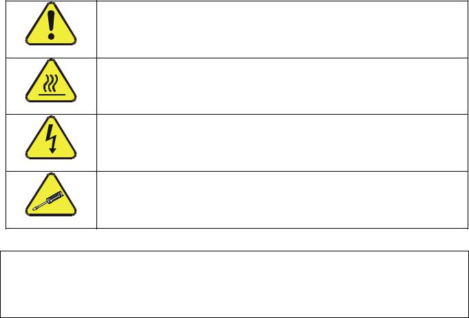
A safety message alerts you to potential hazards that could hurt you or others. Each safety message is associated with a safety alert symbol. These symbols are found in the manual and inside the instrument. The definition of these symbols is described below:
GENERAL SAFETY HAZARD: Refer to the instructions for details on the specific hazard.
CAUTION: Hot Surface Warning
CAUTION: Electrical Shock Hazard
TECHNICIAN SYMBOL: All operations marked with this symbol are to be performed by qualified maintenance personnel only.
CAUTION
The analyzer should only be used for the purpose and in the manner described in this manual. If you use the analyzer in a manner other than that for which it was intended, unpredictable behavior could ensue with possible hazardous consequences.
04584 Rev A1 |
i |

Model GFC7000E Instruction Manual |
GFC7000E Documentation |
|
TABLE OF CONTENTS |
|
|
SAFETY MESSAGES |
I |
|
TABLE OF CONTENTS ...................................................................................................................... |
II |
|
LIST OF APPENDICES.................................................................................................................... |
VII |
|
LIST OF FIGURES |
VII |
|
LIST OF TABLES |
VIII |
|
1. MGFC7000E DOCUMENTATION..................................................................................................... |
1 |
|
1.1. Using This Manual ................................................................................................................... |
1 |
|
2. SPECIFICATIONS, APPROVALS AND WARRANTY.......................................................................... |
5 |
|
2.1. Specifications.......................................................................................................................... |
|
5 |
2.2. CE Mark Compliance ................................................................................................................ |
6 |
|
2.3. Warranty................................................................................................................................ |
|
6 |
3. GETTING STARTED....................................................................................................................... |
9 |
|
3.1. Unpacking and Initial Set Up ..................................................................................................... |
9 |
|
3.1.1. Electrical Connections ...................................................................................................... |
11 |
|
3.1.2. Pneumatic Connections:................................................................................................... |
15 |
|
3.1.2.1. Basic Pneumatic Connections...................................................................................... |
15 |
|
3.1.2.2. Connections with Internal Valve Options Installed.......................................................... |
19 |
|
3.2. Initial Operation .................................................................................................................... |
21 |
|
3.2.1. Startup.......................................................................................................................... |
|
22 |
3.2.2. Warm Up ....................................................................................................................... |
|
23 |
3.2.3. Warning Messages .......................................................................................................... |
24 |
|
3.2.4. Functional Check............................................................................................................. |
25 |
|
3.3. Initial Calibration Procedure .................................................................................................... |
26 |
|
4. FREQUENTLY ASKED QUESTIONS............................................................................................... |
33 |
|
4.1. FAQ’s................................................................................................................................... |
|
33 |
4.2. Glossary............................................................................................................................... |
|
34 |
5. OPTIONAL HARDWARE AND SOFTWARE .................................................................................... |
37 |
|
5.1. Rack Mount Kits (Options 20a, 20b & 21).................................................................................. |
37 |
|
5.2. Current Loop Analog Outputs (Option 41) ................................................................................. |
37 |
|
5.3. Expendable Kits (Options 42C, 42D and 43) .............................................................................. |
38 |
|
5.4. Calibration Valves Options ...................................................................................................... |
38 |
|
5.4.1. Zero/Span/Shutoff Valve (Option 50) ................................................................................. |
38 |
|
5.4.2. Zero/Span/Shutoff with External CO2 Scrubber (Option 51).................................................. |
40 |
|
5.4.3. Zero/Span Valve (Option 52) ............................................................................................ |
40 |
|
5.4.4. Zero/Span Valve with External CO2 Scrubber (Option 53)...................................................... |
41 |
|
5.5. Communication Options.......................................................................................................... |
41 |
|
5.5.1. RS232 Modem Cable (Option 60)....................................................................................... |
41 |
|
5.5.2. RS-232 Multidrop (Option 62) ........................................................................................... |
42 |
|
5.5.3. Ethernet (Option 63) ....................................................................................................... |
42 |
|
5.6. Additional Manuals................................................................................................................. |
42 |
|
5.6.1. Printed Manuals (Option 70) ............................................................................................. |
42 |
|
5.6.2. Manual on CD (Part number 045840200)............................................................................ |
43 |
|
5.7. Extended Warranty (Options 92 & 93) ...................................................................................... |
43 |
|
5.8. Dilution Ratio Option (Option ??) ............................................................................................. |
43 |
|
5.9. Maintenance Mode Switch (Option ??) ...................................................................................... |
43 |
|
5.10. Second Language Switch (Option ??)...................................................................................... |
44 |
|
6. OPERATING INSTRUCTIONS ...................................................................................................... |
45 |
|
6.1. Overview of Operating modes ................................................................................................. |
45 |
|
6.2. Sample Mode........................................................................................................................ |
|
46 |
6.2.1. Test Functions ................................................................................................................ |
46 |
|
6.2.2. Warning Messages .......................................................................................................... |
48 |
|
6.3. Calibration Mode ................................................................................................................... |
50 |
|
6.3.1. SETUP – PASS: Calibration Password Security ..................................................................... |
50 |
|
6.4. SETUP Mode ......................................................................................................................... |
|
52 |
6.4.1. SETUP Mode Password Security......................................................................................... |
53 |
|
6.5. SETUP – CFG: Viewing the Analyzer’s Configuration Information .................................................. |
53 |
|
6.6. SETUP – CLK: Setting the Internal Time-of-Day Clock................................................................. |
54 |
|
04584 Rev A1 |
|
ii |

Model GFC7000E Instruction Manual |
GFC7000E Documentation |
6.7. SETUP – RNGE: Analog Output Reporting Range Configuration..................................................... |
56 |
6.7.1. Physical Range versus Analog Output Reporting Ranges........................................................ |
56 |
6.7.2. Reporting Range Modes ................................................................................................... |
57 |
6.7.3. Single Range mode (SNGL) .............................................................................................. |
58 |
6.7.4. Dual Range Mode (DUAL) ................................................................................................. |
60 |
6.7.5. Auto Range Mode (AUTO)................................................................................................. |
61 |
6.7.6. Range Units ................................................................................................................... |
62 |
6.7.7. Dilution Ratio ................................................................................................................. |
63 |
6.8. SETUP – VARS: Using the Internal Variables.............................................................................. |
64 |
6.9. SETUP – DIAG: Using the Diagnostics Functions......................................................................... |
66 |
6.9.1. Accessing the Diagnostic Features ..................................................................................... |
67 |
6.9.2. Signal I/O ...................................................................................................................... |
67 |
6.9.3. Analog Output Step Test .................................................................................................. |
68 |
6.9.4. Analog I/O Configuration.................................................................................................. |
69 |
6.9.4.1. Analog Output Signal Type and Range Span Selection .................................................... |
71 |
6.9.4.2. Analog Output Calibration Mode.................................................................................. |
71 |
6.9.4.3. Manual Analog Output Calibration and Voltage Adjustment ............................................. |
73 |
6.9.4.4. Current Loop Output Adjustment................................................................................. |
75 |
6.9.4.5. AIN Calibration......................................................................................................... |
77 |
6.9.5. Electric Test ................................................................................................................... |
77 |
6.9.6. Dark Calibration Test ....................................................................................................... |
78 |
6.9.7. Pressure Calibration ........................................................................................................ |
78 |
6.9.8. Flow Calibration .............................................................................................................. |
80 |
6.9.9. Test Channel Output........................................................................................................ |
81 |
6.10. SETUP – COMM: Using the Analyser’s Communication Ports ....................................................... |
82 |
6.10.1. Analyzer ID Code .......................................................................................................... |
82 |
6.10.2. COMM Port Default Settings ............................................................................................ |
83 |
6.10.3. COMM Port Cable Connections......................................................................................... |
84 |
6.10.4. RS-485 Configuration of COM2 ........................................................................................ |
84 |
6.10.5. DTE and DCE Communication.......................................................................................... |
85 |
6.10.6. COMM Port Communication Modes ................................................................................... |
85 |
6.10.7. COM Port Baud Rate ...................................................................................................... |
88 |
6.10.8. COM Port Testing .......................................................................................................... |
89 |
6.10.9. Ethernet Card Configuration............................................................................................ |
89 |
6.10.9.1. Ethernet Card COM2 Communication Modes and Baud Rate........................................... |
90 |
6.10.9.2. Configuring the Ethernet Interface Option using DHCP.................................................. |
90 |
6.10.9.3. Manually Configuring the Network IP Addresses........................................................... |
92 |
6.10.9.4. Changing the Analyzer’s HOSTNAME .......................................................................... |
94 |
6.11. SETUP – ALRM: Using the Gas Concentration Alarms................................................................. |
95 |
6.12. SETUP – DAS: Using the Data Acquisition System (iDAS)........................................................... |
96 |
6.12.1. iDAS Structure.............................................................................................................. |
96 |
6.12.1.1. iDAS Channels........................................................................................................ |
97 |
6.12.1.2. iDAS Parameters..................................................................................................... |
98 |
6.12.1.3. iDAS Triggering Events ............................................................................................ |
98 |
6.12.2. Default iDAS Channels ................................................................................................... |
99 |
6.12.2.1. Viewing iDAS Data and Settings .............................................................................. |
103 |
6.12.2.2. Editing iDAS Data Channels .................................................................................... |
104 |
6.12.2.3. Trigger Events ...................................................................................................... |
105 |
6.12.2.4. Editing iDAS Parameters ........................................................................................ |
106 |
6.12.2.5. Sample Period and Report Period............................................................................. |
107 |
6.12.2.6. Number of Records ............................................................................................... |
109 |
6.12.2.7. RS-232 Report Function ......................................................................................... |
110 |
6.12.2.8. Compact Report.................................................................................................... |
111 |
6.12.2.9. Starting Date ....................................................................................................... |
111 |
6.12.2.10. Disabling/Enabling Data Channels.......................................................................... |
111 |
6.12.2.11. HOLDOFF Feature................................................................................................ |
112 |
6.12.3. Remote iDAS Configuration........................................................................................... |
113 |
6.13. Remote Operation of the Analyzer........................................................................................ |
115 |
6.13.1. Remote Operation Using the External Digital I/O.............................................................. |
115 |
6.13.1.1. Status Outputs ..................................................................................................... |
115 |
04584 Rev A1 |
iii |

Model GFC7000E Instruction Manual |
GFC7000E Documentation |
6.13.1.2. Control Inputs ...................................................................................................... |
116 |
6.13.2. Remote Operation Using the External Serial I/O............................................................... |
117 |
6.13.2.1. Terminal Operating Modes...................................................................................... |
117 |
6.13.2.2. Help Commands in Terminal Mode........................................................................... |
118 |
6.13.2.3. Command Syntax ................................................................................................. |
118 |
6.13.2.4. Data Types .......................................................................................................... |
119 |
6.13.2.5. Status Reporting................................................................................................... |
120 |
6.13.2.6. Remote Access by Modem ...................................................................................... |
120 |
6.13.2.7. COM Port Password Security ................................................................................... |
122 |
6.13.2.8. APICOM Remote Control Program............................................................................ |
122 |
6.13.3. Additional Communications Documentation ..................................................................... |
123 |
6.13.4. Using the MGFC7000E with a Hessen Protocol Network ..................................................... |
123 |
6.13.4.1. General Overview of Hessen Protocol ....................................................................... |
123 |
6.13.4.2. Hessen COMM Port Configuration ............................................................................ |
124 |
6.13.4.3. Activating Hessen Protocol ..................................................................................... |
124 |
6.13.4.4. Selecting a Hessen Protocol Type ............................................................................ |
125 |
6.13.4.5. Setting The Hessen Protocol Response Mode ............................................................. |
126 |
6.13.4.6. Hessen Protocol Gas ID.......................................................................................... |
126 |
6.13.4.7. Setting Hessen Protocol Status Flags ....................................................................... |
127 |
6.13.4.8. Instrument ID Code .............................................................................................. |
128 |
7. CALIBRATION PROCEDURES .................................................................................................... |
129 |
7.1. Before Calibration................................................................................................................ |
129 |
7.1.1. Zero Air and Span Gas................................................................................................... |
129 |
7.1.2. Calibration Gas Traceability ............................................................................................ |
130 |
7.1.3. Data Recording Devices ................................................................................................. |
130 |
7.2. Manual Calibration without Zero/Span Valves .......................................................................... |
130 |
7.3. Manual Calibration Checks .................................................................................................... |
133 |
7.4. Manual Calibration with Zero/Span Valves............................................................................... |
133 |
7.5. Manual Calibration Checks with Zero/Span Valves .................................................................... |
137 |
7.5.1. Zero/Span Calibration on Auto Range or Dual Ranges......................................................... |
137 |
7.5.2. Use of Zero/Span Valves with Remote Contact Closure ....................................................... |
138 |
7.6. Automatic Zero/Span Cal/Check (AutoCal) .............................................................................. |
139 |
7.6.1. AutoCal with Auto or Dual Reporting Ranges Modes Selected............................................... |
142 |
7.7. Calibration Quality............................................................................................................... |
142 |
8. EPA PROTOCOL CALIBRATION ................................................................................................. |
143 |
9. MAINTENANCE SCHEDULE & PROCEDURES .............................................................................. |
145 |
9.1. Maintenance Schedule.......................................................................................................... |
145 |
9.2. Predicting Failures Using the Test Functions ............................................................................ |
148 |
9.3. Maintenance Procedures ....................................................................................................... |
148 |
9.3.1. Replacing the Sample Particulate Filter............................................................................. |
149 |
9.3.2. Rebuilding the Sample Pump .......................................................................................... |
150 |
9.3.3. Performing Leak Checks................................................................................................. |
150 |
9.3.3.1. Vacuum Leak Check and Pump Check ........................................................................ |
150 |
9.3.3.2. Pressure Leak Check ............................................................................................... |
150 |
9.3.4. Performing a Sample Flow Check..................................................................................... |
151 |
9.3.5. Cleaning the Optical Bench ............................................................................................. |
151 |
9.3.6. Cleaning Exterior Surfaces of the MGFC7000E ................................................................... |
151 |
10. THEORY OF OPERATION......................................................................................................... |
153 |
10.1. Measurement Method ......................................................................................................... |
153 |
10.1.1. Beer’s Law ................................................................................................................. |
153 |
10.1.2. Measurement Fundamentals ......................................................................................... |
154 |
10.1.3. Gas Filter Correlation ................................................................................................... |
154 |
10.1.4. Ambient CO2 Interference Rejection ............................................................................... |
158 |
10.2. Pneumatic Operation.......................................................................................................... |
158 |
10.2.1. Sample Gas Flow......................................................................................................... |
159 |
10.2.1.1. Critical Flow Orifice ............................................................................................... |
159 |
10.2.1.2. Sample Pressure Sensor ........................................................................................ |
160 |
10.2.1.3. Sample Flow Sensor .............................................................................................. |
160 |
10.2.1.4. Valve Options ....................................................................................................... |
161 |
10.2.2. Purge Gas Pressure and Flow Control ............................................................................. |
161 |
04584 Rev A1 |
iv |

Model GFC7000E Instruction Manual |
GFC7000E Documentation |
10.3. Electronic Operation........................................................................................................... |
161 |
10.3.1. Overview ................................................................................................................... |
161 |
10.3.2. CPU........................................................................................................................... |
163 |
10.3.3. Optical Bench & GFC Wheel........................................................................................... |
163 |
10.3.3.1. Sample Gas and GFC Temperature Control ............................................................... |
163 |
10.3.3.2. IR Source ............................................................................................................ |
164 |
10.3.3.3. GFC Wheel........................................................................................................... |
164 |
10.3.3.4. IR Photo-Detector ................................................................................................. |
165 |
10.3.4. Synchronous Demodulator (Sync/Demod) Assembly......................................................... |
165 |
10.3.4.1. Overview ............................................................................................................. |
165 |
10.3.4.2. Signal Synchronization and Demodulation ................................................................ |
166 |
10.3.4.3. Phase Lock Warning .............................................................................................. |
167 |
10.3.4.4. Sync/Demod Status LED’s ...................................................................................... |
167 |
10.3.4.5. Photo-Detector Temperature Control........................................................................ |
168 |
10.3.4.6. Dark Calibration Switch.......................................................................................... |
168 |
10.3.4.7. Electric Test Switch ............................................................................................... |
168 |
10.3.5. Relay Board................................................................................................................ |
168 |
10.3.5.1. Status LED’s......................................................................................................... |
169 |
10.3.5.2. I2C Watch Dog Circuitry ........................................................................................ |
170 |
10.3.6. Mother Board.............................................................................................................. |
170 |
10.3.6.1. A to D Conversion ................................................................................................. |
170 |
10.3.6.2. Sensor Inputs....................................................................................................... |
171 |
10.3.6.3. Thermistor Interface.............................................................................................. |
171 |
10.3.6.4. Analog Outputs..................................................................................................... |
172 |
10.3.6.5. Internal Digital I/O................................................................................................ |
172 |
10.3.6.6. External Digital I/O ............................................................................................... |
173 |
10.3.7. I2C Data Bus............................................................................................................... |
173 |
10.3.8. Power Supply/ Circuit Breaker ....................................................................................... |
173 |
10.4. Interface .......................................................................................................................... |
174 |
10.4.1. Front Panel Interface ................................................................................................... |
175 |
10.4.1.1. Analyzer Status LED’s............................................................................................ |
175 |
10.4.1.2. Keyboard............................................................................................................. |
176 |
10.4.1.3. Display................................................................................................................ |
176 |
10.4.1.4. Keyboard/Display Interface Electronics..................................................................... |
177 |
10.5. Software Operation ............................................................................................................ |
178 |
10.5.1. Adaptive Filter ............................................................................................................ |
179 |
10.5.2. Calibration - Slope and Offset........................................................................................ |
179 |
10.5.3. Measurement Algorithm ............................................................................................... |
180 |
10.5.4. Temperature and Pressure Compensation ....................................................................... |
180 |
10.5.5. Internal Data Acquisition System (iDAS) ......................................................................... |
180 |
11. TROUBLESHOOTING & REPAIR PROCEDURES ........................................................................ |
183 |
11.1. General Troubleshooting Hints ............................................................................................. |
183 |
11.1.1. Interpreting WARNING Messages................................................................................... |
184 |
11.1.2. Fault Diagnosis with TEST Functions............................................................................... |
186 |
11.1.3. Using the Diagnostic Signal I/O Function......................................................................... |
188 |
11.1.4. Internal Electronic Status LED’s..................................................................................... |
189 |
11.1.4.1. CPU Status Indicator ............................................................................................. |
189 |
11.1.4.2. Sync Demodulator Status LED’s .............................................................................. |
190 |
11.1.4.3. Relay Board Status LED’s ....................................................................................... |
191 |
11.1.5. Gas Flow Problems ...................................................................................................... |
192 |
11.1.6. Typical Sample Gas Flow Problems................................................................................. |
193 |
11.1.6.1. Flow is Zero ......................................................................................................... |
193 |
11.1.6.2. Low Flow ............................................................................................................. |
193 |
11.1.6.3. High Flow ............................................................................................................ |
194 |
11.1.6.4. Displayed Flow = “XXXX” ....................................................................................... |
194 |
11.1.6.5. Actual Flow Does Not Match Displayed Flow .............................................................. |
194 |
11.1.6.6. Sample Pump ....................................................................................................... |
194 |
11.1.7. Poor or Stopped Flow of Purge Gas ................................................................................ |
194 |
11.2. Calibration Problems .......................................................................................................... |
195 |
11.2.1. Miss-Calibrated ........................................................................................................... |
195 |
04584 Rev A1 |
v |

Model GFC7000E Instruction Manual |
GFC7000E Documentation |
11.2.2. Non-Repeatable Zero and Span ..................................................................................... |
195 |
11.2.3. Inability to Span – No SPAN Key.................................................................................... |
196 |
11.2.4. Inability to Zero – No ZERO Key .................................................................................... |
196 |
11.3. Other Performance Problems ............................................................................................... |
196 |
11.3.1. Temperature Problems ................................................................................................. |
197 |
11.3.1.1. Box or Sample Temperature ................................................................................... |
197 |
11.3.1.2. Bench Temperature............................................................................................... |
197 |
11.3.1.3. GFC Wheel Temperature ........................................................................................ |
198 |
11.3.1.4. IR Photo-Detector TEC Temperature ........................................................................ |
198 |
11.3.2. Excessive Noise........................................................................................................... |
198 |
11.4. Subsystem Checkout.......................................................................................................... |
199 |
11.4.1. AC Mains Configuration ................................................................................................ |
199 |
11.4.2. DC Power Supply......................................................................................................... |
200 |
11.4.3. I2C Bus ...................................................................................................................... |
200 |
11.4.4. Keyboard/Display Interface........................................................................................... |
201 |
11.4.5. Relay Board................................................................................................................ |
201 |
11.4.6. Sensor Assembly......................................................................................................... |
202 |
11.4.6.1. Sync/Demodulator Assembly .................................................................................. |
202 |
11.4.6.2. Opto Pickup Assembly ........................................................................................... |
202 |
11.4.6.3. GFC Wheel Drive................................................................................................... |
203 |
11.4.6.4. IR Source ............................................................................................................ |
203 |
11.4.6.5. Pressure/Flow Sensor Assembly .............................................................................. |
203 |
11.4.7. Motherboard............................................................................................................... |
204 |
11.4.7.1. A/D Functions....................................................................................................... |
204 |
11.4.7.2. Analog Outputs: Voltage ........................................................................................ |
204 |
11.4.7.3. Analog Outputs: Current Loop................................................................................. |
204 |
11.4.7.4. Status Outputs ..................................................................................................... |
205 |
11.4.7.5. Control Inputs – Remote Zero, Span........................................................................ |
205 |
11.4.8. CPU........................................................................................................................... |
206 |
11.4.9. RS-232 Communications .............................................................................................. |
206 |
11.4.9.1. General RS-232 Troubleshooting ............................................................................. |
206 |
11.4.9.2. Troubleshooting Analyzer/Modem or Terminal Operation............................................. |
207 |
11.5. Repair Procedures.............................................................................................................. |
207 |
11.5.1. Repairing Sample Flow Control Assembly ........................................................................ |
207 |
11.5.2. Removing/Replacing the GFC Wheel............................................................................... |
209 |
11.5.3. Disk-On-Chip Replacement Procedure............................................................................. |
210 |
12. A PRIMER ON ELECTRO-STATIC DISCHARGE.......................................................................... |
213 |
12.1. How Static Charges are Created........................................................................................... |
213 |
12.2. How Electro-Static Charges Cause Damage ........................................................................... |
214 |
12.3. Common Myths About ESD Damage ..................................................................................... |
215 |
12.4. Basic Principles of Static Control .......................................................................................... |
216 |
12.4.1. General Rules ............................................................................................................. |
216 |
12.4.2. Basic anti-ESD Procedures for Analyzer Repair and Maintenance ........................................ |
218 |
12.4.2.1. Working at the Instrument Rack.............................................................................. |
218 |
12.4.2.2. Working at a Anti-ESD Work Bench.......................................................................... |
218 |
12.4.2.3. Transferring Components from Rack To Bench and Back ............................................. |
219 |
12.4.2.4. Opening Shipments from and Packing Components for Return to Teledyne Instruments |
|
Customer Service. .............................................................................................................. |
219 |
04584 Rev A1 |
vi |

Model GFC7000E Instruction Manual GFC7000E Documentation
LIST OF APPENDICES
APPENDIX A - VERSION SPECIFIC SOFTWARE DOCUMENTATION
APPENDIX A-1: MGFC7000E Software Menu Trees, Revision E.0
APPENDIX A-2: Setup Variables For Serial I/O, Revision E.0
APPENDIX A-3: Warnings and Test Functions, Revision E.0
APPENDIX A-4: MGFC7000E Signal I/O Definitions, Revision E.0
APPENDIX A-5: MGFC7000E iDAS Functions, Revision E.0
APPENDIX A-6: Terminal Command Designators, Revision E.0
APPENDIX B - GFC7000E SPARE PARTS LIST
APPENDIX C - REPAIR QUESTIONNAIRE - MGFC7000E
APPENDIX D - ELECTRONIC SCHEMATICS
LIST OF FIGURES
Figure 3-1: Removal of Shipping Screws.......................................................................... |
10 |
||
Figure 3-2: Rear Panel Layout........................................................................................ |
12 |
||
Figure 3-3: Pneumatic Connections–Basic Configuration–Using Bottled Span Gas .................. |
16 |
||
Figure 3-4: Pneumatic Connections–Basic Configuration–Using Gas Dilution Calibrator ........... |
17 |
||
Figure 3-5: Pneumatic Connections–MGFC7000E with Zero/Span/Shutoff Valves (OPT 50)...... |
19 |
||
Figure 3-6 |
Pneumatic Connections–MGFC7000E with Zero/Span/Shutoff Valves and External |
||
|
Zero Air Scrubber (OPT 51).......................................................................... |
19 |
|
Figure 3-7: Pneumatic Connections–MGFC7000E with Zero/Span Valves (OPT 52) ................. |
20 |
||
Figure 3-8: |
Pneumatic Connections–MGFC7000E with Zero/Span Valves with External Zero air |
||
|
Scrubber (OPT 53)...................................................................................... |
20 |
|
Figure 3-9: Example of Pneumatic Set up for Multipoint Calibration of M360 ......................... |
21 |
||
Figure 3-10: Front Panel Layout ....................................................................................... |
23 |
||
Figure 3-11: |
Assembly Layout.......................................................................................... |
30 |
|
Figure 3-12: Optical Bench Layout .................................................................................... |
31 |
||
Figure 3-13: Internal Pneumatic Flow – Basic Configuration ................................................. |
31 |
||
Figure 5-1: Current Loop Option Installed on the Motherboard............................................ |
37 |
||
Figure 5-2: Internal Pneumatic Flow – Zero/Span/Shutoff Valves OPT 50 & 51 ...................... |
39 |
||
Figure 5-3: Internal Pneumatic Flow – Zero/Span OPT 52 & 53 ........................................... |
41 |
||
Figure 5-4: GFC7000E Ethernet Card and rear panel With Ethernet Installed......................... |
42 |
||
Figure 6-1: Front Panel Display ...................................................................................... |
45 |
||
Figure 6-2 |
Viewing MGFC7000E TEST Functions............................................................... |
48 |
|
Figure 6-3 |
Viewing and Clearing MGFC7000E WARNING Messages...................................... |
50 |
|
Figure 6-4: Analog Output Connector Pin Out ................................................................... |
56 |
||
Figure 6-5: Setup for Calibrating Analog Voltage Outputs................................................... |
74 |
||
Figure 6-6: Setup for Calibrating Current Outputs ............................................................. |
75 |
||
Figure 6-7: Default iDAS Channels Setup....................................................................... |
101 |
||
Figure 6-8: APICOM user interface for configuring the iDAS.............................................. |
113 |
||
Figure 6-9: iDAS Configuration Through a Terminal Emulation Program.............................. |
114 |
||
Figure 6-10: Status Output Connector............................................................................. |
115 |
||
Figure 6-11: |
Control Inputs ........................................................................................... |
117 |
|
Figure 6-12: APICOM Remote Control Program Interface.................................................... |
123 |
||
Figure 7-1: Pneumatic Connections–Basic Configuration–Using Bottled Span Gas ................ |
130 |
||
Figure 7-2: Pneumatic Connections–Basic Configuration–Using Gas Dilution Calibrator ......... |
131 |
||
Figure 7-3: Pneumatic Connections–MGFC7000E with Zero/Span/Shutoff Valves (OPT 50).... |
134 |
||
Figure 7-4 |
Pneumatic Connections–MGFC7000E with Zero/Span/Shutoff Valves and External |
||
|
Zero Air Scrubber (OPT 51)........................................................................ |
134 |
|
Figure 7-5: Pneumatic Connections–MGFC7000E with Zero/Span Valves (OPT 52) ............... |
135 |
||
|
|
|
|
04584 Rev A1 |
vii |
||

Model GFC7000E Instruction Manual |
GFC7000E Documentation |
||
Figure 7-6: |
Pneumatic Connections–MGFC7000E with Zero/Span Valves with External Zero air |
||
|
Scrubber (OPT 53).................................................................................... |
|
135 |
Figure 9-1: Sample Particulate Filter Assembly ............................................................... |
|
149 |
|
Figure 10-1: |
Measurement Fundamentals ........................................................................ |
|
154 |
Figure 10-2: |
GFC Wheel ................................................................................................ |
|
155 |
Figure 10-3: Measurement Fundamentals with GFC Wheel ................................................. |
|
155 |
|
Figure 10-4: Affect of CO2 in the Sample on CO2 MEAS & CO2 REF...................................... |
|
156 |
|
Figure 10-5: Effects of Interfering Gas on CO2 MEAS & CO2 REF......................................... |
|
157 |
|
Figure 10-6: Chopped IR Signal...................................................................................... |
|
157 |
|
Figure 10-7: Internal Pneumatic Flow – Basic Configuration ............................................... |
|
159 |
|
Figure 10-8: Flow Control Assembly & Critical Flow Orifice ................................................. |
|
160 |
|
Figure 10-9: GFC7000E Electronic Block Diagram ............................................................. |
|
162 |
|
Figure 10-10: GFC Light Mask.......................................................................................... |
|
164 |
|
Figure 10-11: Segment Sensor and M/R Sensor Output ....................................................... |
|
165 |
|
Figure 10-12: GFC7000E Sync / Demod Block Diagram ....................................................... |
|
166 |
|
Figure 10-13: Sample & Hold Timing................................................................................. |
|
167 |
|
Figure 10-14: Location of relay board Status LED’s ............................................................. |
|
170 |
|
Figure 10-15: Power Distribution Block Diagram ................................................................. |
|
174 |
|
Figure 10-16: Interface Block Diagram.............................................................................. |
|
175 |
|
Figure 10-17: MGFC7000E Front Panel Layout.................................................................... |
|
175 |
|
Figure 10-18: Keyboard and Display Interface Block Diagram............................................... |
|
177 |
|
Figure 10-19: Basic Software Operation ............................................................................ |
|
179 |
|
Figure 11-1: Viewing and Clearing Warning Messages........................................................ |
|
184 |
|
Figure 11-2: Example of Signal I/O Function .................................................................... |
|
189 |
|
Figure 11-3: CPU Status Indicator .................................................................................. |
|
190 |
|
Figure 11-4: Sync/Demod Board Status LED Locations ...................................................... |
|
191 |
|
Figure 11-5: Relay Board Status LEDs............................................................................. |
|
191 |
|
Figure 11-6: Critical Flow Restrictor Assembly Disassembly ................................................ |
|
208 |
|
Figure 11-7: Opening the GFC Wheel Housing .................................................................. |
|
209 |
|
Figure 11-8: Removing the GFC Wheel ............................................................................. |
|
210 |
|
Figure 12-1: |
Triboelectric Charging................................................................................. |
|
213 |
Figure 12-2: Basic anti-ESD Work Station........................................................................ |
|
216 |
|
Figure A-1: Basic Sample Display Menu .......................................................................... |
|
223 |
|
Figure A-2: Sample Display Menu - Units with Z/S Valve or IZS Option installed |
................... 224 |
||
Figure A-3: Primary Setup Menu (Except iDAS) ............................................................... |
|
225 |
|
Figure A-4: |
Primary Setup Menu (iDAS) ......................................................................... |
|
226 |
Figure A-5: Secondary Setup Menu (COMM & VARS) ........................................................ |
|
227 |
|
Figure A-6: Secondary Setup Menu (COMM Menu with Ethernet Card)................................. |
228 |
||
Figure A-7: Secondary Setup Menu (COMM Menu with HESSEN) ........................................ |
|
229 |
|
Figure A-8: Secondary Setup Menu (DIAG) ..................................................................... |
|
230 |
|
LIST OF TABLES |
|
|
|
Table 2-1: Model GFC7000E Basic Unit Specifications .......................................................... |
|
5 |
|
Table 3-1: GFC7000E Analog Output Pin Outs .................................................................. |
|
13 |
|
Table 3-2: GFC7000E Status Output Pin Outs ................................................................... |
|
14 |
|
Table 3-3: GFC7000E Control Input Pin Outs .................................................................... |
|
15 |
|
Table 3-4: Model GFC7000E Rear Panel Pneumatic Connections .......................................... |
|
16 |
|
Table 3-5: Front Panel Display During System Warm-Up .................................................... |
|
23 |
|
Table 3-6: Possible Warning Messages at Start-Up ............................................................ |
|
24 |
|
Table 5-1: Zero/Span Valve Operating States for Options 50 & 51....................................... |
|
38 |
|
Table 5-2: Zero/Span Valve Operating States for Options 52 & 53....................................... |
|
40 |
|
Table 6-1: Analyzer Operating modes.............................................................................. |
|
46 |
|
04584 Rev A1 |
|
viii |
|

Model GFC7000E Instruction Manual |
GFC7000E Documentation |
||
Table 6-2: Test Functions Defined................................................................................... |
|
46 |
|
Table 6-3: List of Warning Messages ............................................................................... |
|
49 |
|
Table 6-4: Primary Setup Mode Features and Functions ..................................................... |
|
52 |
|
Table 6-5: Secondary Setup Mode Features and Functions ................................................. |
|
52 |
|
Table 6-6: Variable Names (VARS) Revision B.3 ............................................................... |
|
64 |
|
Table 6-7: GFC7000E Diagnostic (DIAG) Functions............................................................ |
|
66 |
|
Table 6-8: DIAG - Analog I/O Functions........................................................................... |
|
69 |
|
Table 6-9: Analog Output Voltage Ranges........................................................................ |
|
69 |
|
Table 6-10: Analog Output Current Loop Range.................................................................. |
|
70 |
|
Table 6-11: Analog Output Pin Assignments....................................................................... |
|
70 |
|
Table 6-12: Voltage Tolerances for Analog Output Calibration............................................... |
|
73 |
|
Table 6-13: Current Loop Output Calibration with Resistor ................................................... |
|
76 |
|
Table 6-14: Test Parameters Available for Analog Output A3 ................................................ |
|
81 |
|
Table 6-15: COM1 and COM2 DB-9 Pin Assignments............................................................ |
|
85 |
|
Table 6-16: COMM Port Communication modes................................................................... |
|
86 |
|
Table 6-17: Ethernet Status Indicators.............................................................................. |
|
89 |
|
Table 6-18: LAN/Internet Configuration Properties .............................................................. |
|
90 |
|
Table 6-19: Internet Configuration Keypad Functions .......................................................... |
|
94 |
|
Table 6-20: CO2 Concentration Alarm Default Settings......................................................... |
|
95 |
|
Table 6-21: Front Panel LED Status Indicators for iDAS ....................................................... |
|
96 |
|
Table 6-22: iDAS Data Channel Properties ......................................................................... |
|
97 |
|
Table 6-23: iDAS Data Parameter Functions....................................................................... |
|
98 |
|
Table 6-24: Status Output Pin Assignments ..................................................................... |
|
116 |
|
Table 6-25: Control Input Pin Assignments ...................................................................... |
|
116 |
|
Table 6-26: Terminal Mode Software Commands .............................................................. |
|
118 |
|
Table 6-27: |
Command Types ......................................................................................... |
|
119 |
Table 6-28: Serial Interface Documents........................................................................... |
|
123 |
|
Table 6-29: RS-232 Communication Parameters for Hessen Protocol |
................................... |
124 |
|
Table 6-30: Teledyne Instruments Hessen Protocol Response Modes |
................................... |
126 |
|
Table 6-31: Default Hessen Status Bit Assignments........................................................... |
|
127 |
|
Table 7-1: |
AUTOCAL Modes ......................................................................................... |
|
139 |
Table 7-2: AutoCal ATTRIBUTE Setup Parameters ........................................................... |
|
139 |
|
Table 7-3: Calibration Data Quality Evaluation................................................................ |
|
142 |
|
Table 9-1: GFC7000E Maintenance Schedule .................................................................. |
|
146 |
|
Table 9-2: GFC7000E Test Function Record.................................................................... |
|
147 |
|
Table 9-3: Predictive uses for Test Functions.................................................................. |
|
148 |
|
Table 10-1: Sync/Demod Status LED Activity ................................................................... |
|
168 |
|
Table 10-2: Relay Board Status LED’s ............................................................................. |
|
169 |
|
Table 10-3: Front Panel Status LED’s .............................................................................. |
|
176 |
|
Table 11-1: Warning Messages - Indicated Failures ........................................................... |
|
185 |
|
Table 11-2: Test Functions - Indicated Failures................................................................. |
|
187 |
|
Table 11-3: Sync/Demod Board Status Failure Indications ................................................. |
|
190 |
|
Table 11-4: I2C Status LED Failure Indications ................................................................. |
|
191 |
|
Table 11-5: Relay Board Status LED Failure Indications ..................................................... |
|
192 |
|
Table 11-6: DC Power Test Point and Wiring Color Codes ................................................... |
|
200 |
|
Table 11-7: DC Power Supply Acceptable Levels ............................................................... |
|
200 |
|
Table 11-8: Relay Board Control Devices ......................................................................... |
|
201 |
|
Table 11-9: Opto Pickup Board Nominal Output Frequencies............................................... |
|
202 |
|
Table 11-10: Analog Output Test Function - Nominal Values Voltage Outputs.......................... |
204 |
||
Table 11-11: Analog Output Test Function - Nominal Values Current Outputs ......................... |
205 |
||
Table 11-12: Status Outputs Check .................................................................................. |
|
205 |
|
Table 12-1: Static Generation Voltages for Typical Activities............................................... |
|
214 |
|
Table 12-2: Sensitivity of Electronic Devices to Damage by ESD ......................................... |
|
214 |
|
Table A-1: GFC7000E Setup Variables, Revision E.0 ........................................................ |
|
231 |
|
04584 Rev A1 |
|
ix |
|
Model GFC7000E Instruction Manual |
GFC7000E Documentation |
Table A-2: GFC7000E Warning Messages, Revision E.0 .................................................... |
238 |
Table A-3: GFC7000E Test Functions, Revision E.0.......................................................... |
239 |
Table A-4: GFC7000E Signal I/O Definitions, Revision E.0 ................................................ |
240 |
Table A-5: GFC7000E DAS Trigger Events, Revision E.0 ................................................... |
243 |
Table A-6: GFC7000E iDAS Functions, Revision E.0 ......................................................... |
244 |
Table A-7: Terminal Command Designators, Revision E.0................................................. |
245 |
Table D-1: List of Included Electronic Schematics............................................................ |
251 |
User Notes
04584 Rev A1 |
x |
Model GFC7000E Instruction Manual |
MGFC7000E Documentation |
1. MGFC7000E DOCUMENTATION
Thank you for purchasing the Model GFC7000E Gas Filter Correlation Carbon Dioxide Analyzer!
The documentation for this instrument is available in several different formats:
•Printed format, part number 045840100
•Electronic format on a CD-ROM, part number 045840200
The electronic manual is in Adobe® Systems Inc. “Portable Document Format”. The Adobe® Acrobat Reader® software, which is necessary to view these files, can be downloaded for free from the internet at http://www.adobe.com/.
The electronic version of the manual has many advantages:
•Keyword and phrase search feature
•Figures, tables and internet addresses are linked so that clicking on the item will display the associated feature or open the website.
•A list of chapters and sections as well as thumbnails of each page are displayed to the left of the text.
•Entries in the table of contents are linked to the corresponding locations in the manual.
•Ability to print sections (or all) of the manual
Additional documentation for the Model GFC7000E CO2 Analyzer is available from Teledyne Analytical Instruments’ website at http://www.teledyne-ai.com/manuals/
•APICOM software manual, part number 03945
•Multi-drop manual, part number 01842
•DAS Manual, part number 02837.
1.1. Using This Manual
This manual has the following data structures:
1.0 Table of Contents:
Outlines the contents of the manual in the order the information is presented. This is a good overview of the topics covered in the manual. There is also a list of tables, a list of figures and a list of appendices. In the electronic version of the manual, clicking on a any of these table entries automatically views that section.
04584 Rev A1 |
1 |
Model GFC7000E Instruction Manual |
MGFC7000E Documentation |
2.0 Specifications and Warranty
This section contains a list of the analyzer’s performance specifications, a description of the conditions and configuration under which EPA equivalency was approved and Teledyne Instruments Incorporated’s warranty statement.
3.0 Getting Started:
A concise set of instructions for setting up, installing and running your analyzer for the first time.
4.0 FAQ:
Answers to the most frequently asked questions about operating the analyzer.
5.0 Optional Hardware & Software
A description of optional equipment to add functionality to your analyzer.
6.0 Operation Instructions
This section includes step by step instructions for operating the analyzer and using its various features and functions.
7.0 Calibration Procedures
General information and step by step instructions for calibrating your analyzer.
8.0 EPA Protocol Calibration
Because CO2 is not declared a criteria air pollutant by the US EPA, EPA equivalency is not required for this type of analyzer. Therefore no special calibration methods are needed to satisfy EPA requirements.
9.0 Instrument Maintenance
Description of certain preventative maintenance procedures that should be regularly performed on you instrument to keep it in good operating condition. This section also includes information on using the iDAS to record diagnostic functions useful in predicting possible component failures before they happen.
10.0Theory of Operation
An in-depth look at the various principals by which your analyzer operates as well as a description of how the various electronic, mechanical and pneumatic components of the instrument work and interact with each other. A close reading of this section is invaluable for understanding the instrument’s operation.
11.0Troubleshooting Section:
This section includes pointers and instructions for diagnosing problems with the instrument, such as excessive noise or drift, as well as instructions on performing repairs of the instrument’s major subsystems.
04584 Rev A1 |
2 |

Model GFC7000E Instruction Manual |
MGFC7000E Documentation |
Appendices:
For easier access and better updating, some information has been separated out of the manual and placed in a series of appendices at the end of this manual. These include: software menu trees, warning messages, definitions of iDAS & serial I/O variables, spare parts list, repair questionnaire, interconnect listing and drawings, and electronic schematics.
NOTE
Throughout this manual, words printed in capital, bold letters, such as SETUP or ENTR represent messages as they appear on the analyzer’s front panel display.
NOTE
The flowcharts in this manual contain typical representations of the analyzer’s display during the various operations being described. These representations are not intended to be exact and may differ slightly from the actual display of your instrument.
User Notes
04584 Rev A1 |
3 |

Model GFC7000E Instruction Manual |
Specifications, Approvals and Warranty |
|
||
|
|
|
|
|
|
|
|
|
|
|
|
|
|
|
|
|
|
|
|
|
|
|
|
|
|
|
|
|
|
|
|
|
|
|
|
|
|
|
|
|
|
|
|
|
|
|
|
|
|
|
|
|
|
|
|
|
|
|
|
|
|
|
|
|
|
|
|
|
|
|
|
|
|
|
|
|
|
|
|
|
|
|
|
|
|
|
|
|
|
|
|
|
|
|
|
|
|
|
|
|
|
|
|
|
|
|
|
|
|
|
|
|
|
|
|
|
|
|
|
|
|
|
|
|
|
|
|
|
|
|
|
|
|
|
|
|
|
|
|
|
|
|
|
|
|
|
|
|
|
|
|
|
|
|
04584 Rev A1 |
5 |
Model GFC7000E Instruction Manual |
Specifications, Approvals and Warranty |
2.2. CE Mark Compliance
Emissions Compliance
The Teledyne Instruments Model GFC7000E Gas Filter Correlation CO2 Analyzer was tested and found to be fully compliant with:
EN61326 (1997 w/A1: 98) Class A, FCC Part 15 Subpart B Section 15.107 Class A, ICES-003 Class A (ANSI C63.4 1992) & AS/NZS 3548 (w/A1 & A2; 97) Class A.
Tested on 11-29-2001 at CKC Laboratories, Inc., Report Number CE01-249.
Safety Compliance
The Teledyne Instruments Model GFC7000E Gas Filter Correlation CO2 Analyzer was tested and found to be fully compliant with:
IEC 61010-1:90 + A1:92 + A2:95,
Tested on 02-06-2002 at Nemko, Report Number 2002-012219.
2.3. Warranty
Warranty Policy (02024)
Prior to shipment, Teledyne Instruments Incorporated equipment is thoroughly inspected and tested. Should equipment failure occur, Teledyne Instruments Incorporated assures its customers that prompt service and support will be available.
Coverage
After the warranty period and throughout the equipment lifetime, Teledyne Instruments Incorporated stands ready to provide on-site or in-plant service at reasonable rates similar to those of other manufacturers in the industry. All maintenance and the first level of field troubleshooting is to be performed by the customer.
Non-API Manufactured Equipment
Equipment provided but not manufactured by Teledyne Instruments Incorporated is warranted and will be repaired to the extent and according to the current terms and conditions of the respective equipment manufacturers warranty.
General
Teledyne Instruments Incorporated warrants each product manufactured by Teledyne Instruments Incorporated to be free from defects in material and workmanship under normal use and service for a period of one year from the date of delivery. All replacement parts and repairs are warranted for 90 days after the purchase.
If a product fails to conform to its specifications within the warranty period, Teledyne Instruments Incorporated shall correct such defect by, in Teledyne Instruments Incorporated’s discretion, repairing or replacing such defective product or refunding the purchase price of such product.
04584 Rev A1 |
6 |

Model GFC7000E Instruction Manual |
Specifications, Approvals and Warranty |
The warranties set forth in this section shall be of no force or effect with respect to any product:
(i) that has been altered or subjected to misuse, negligence or accident, or (ii) that has been used in any manner other than in accordance with the instruction provided by TELEDYNE ANALYTICAL INSTRUMENTS or (iii) not properly maintained.
THE WARRANTIES SET FORTH IN THIS SECTION AND THE REMEDIES THEREFORE ARE EXCLUSIVE AND IN LIEU OF ANY IMPLIED WARRANTIES OF MERCHANTABILITY, FITNESS FOR PARTICULAR PURPOSE OR OTHER WARRANTY OF QUALITY, WHETHER EXPRESSED OR IMPLIED. THE REMEDIES SET FORTH IN THIS SECTION ARE THE EXCLUSIVE REMEDIES FOR BREACH OF ANY WARRANTY CONTAINED HEREIN. Teledyne Instruments Incorporated SHALL NOT BE LIABLE FOR ANY INCIDENTAL OR CONSEQUENTIAL DAMAGES ARISING OUT OF OR RELATED TO THIS AGREEMENT OF TELEDYNE INSTRUMENTS INCORPORATED’S PERFORMANCE HEREUNDER, WHETHER FOR BREACH OF WARRANTY OR OTHERWISE.
Terms and Conditions
All units or components returned to Teledyne Amnalytical Instruments should be properly packed for handling and returned freight prepaid to the nearest designated Service Center. After the repair, the equipment will be returned, freight prepaid.
User Notes
04584 Rev A1 |
7 |

Model GFC7000E Instruction Manual |
Getting Started |
3. GETTING STARTED
3.1. Unpacking and Initial Set Up
CAUTION
To avoid personal injury, always use two persons to lift and carry the Model GFC7000E.
1.Verify that there is no apparent external shipping damage. If damage has occurred, please advise the shipper first, then Teledyne Analytical Instruments.
2.Included with your analyzer is a printed record of the final performance characterization performed on your instrument at the factory. This record, titled Final Test and Validation Data Sheet (part number 04307) is an important quality assurance and calibration record for this instrument. It should be placed in the quality records file for this instrument.
3.Carefully remove the top cover of the analyzer and check for internal shipping damage.
•Remove the set screw located in the top, center of the rear panel.
•Remove the four screws fastening the top cover to the unit (two per side).
•Lift the cover straight up. Do not slide backwards.
NOTE
Some versions of the GFC7000E CO2 Analyzer may have a spring loaded fastener at the top center of the rear panel and as many as eight screws (four per side) fastening the top cover to the chassis.
NOTE
Static sensitive parts are present on PCA (Printed Circuit Assemblies). Before touching PCAs, touch a bare metal part of the chassis to discharge any electrostatic potentials or connect a grounding strap to your wrist.
CAUTION
Never disconnect PCAs, wiring harnesses or electronic subassemblies while under power.
4.Inspect the interior of the instrument to make sure all circuit boards and other components are in good shape and properly seated.
04584 Rev A1 |
9 |
Model GFC7000E Instruction Manual |
Getting Started |
5.Check the connectors of the various internal wiring harnesses and pneumatic hoses to make sure they are firmly and properly seated.
6.Verify that all of the optional hardware ordered with the unit has been installed. These are listed on the paperwork accompanying the analyzer.
7.Once you have determined that no shipping damage exists, and the unit includes all expected hardware options, remove all red colored shipping screws from the bottom of the chassis as shown in Figure 3-1.
Shipping
Screws
Figure 3-1: Removal of Shipping Screws
NOTE
Save these shipping screws and re-install them whenever the unit is shipped to another location.
04584 Rev A1 |
10 |

Model GFC7000E Instruction Manual |
Getting Started |
8.VENTILATION CLEARANCE: Whether the analyzer is set up on a bench or installed into an instrument rack, be sure to leave sufficient ventilation clearance.
AREA |
MINIMUM REQUIRED CLEARANCE |
|
|
Back of the instrument |
4 in. |
|
|
Sides of the instrument |
1 in. |
|
|
Above and below the instrument |
1 in. |
|
|
•Various rack mount kits are available for this analyzer. See Section 5.1 of this manual for more information.
3.1.1. Electrical Connections
CAUTION
Check the voltage and frequency label on the rear panel of the instrument (See Figure 3-2) for compatibility with the local power before plugging the MGFC7000E into line power.
Do not plug in the power cord if the voltage or frequency is incorrect.
CAUTION
Power connection must have functioning ground connection.
Do not defeat the ground wire on power plug.
CAUTION
Turn off analyzer power before disconnecting or connecting electrical subassemblies.
Do not operate with cover off.
04584 Rev A1 |
11 |

Model GFC7000E Instruction Manual |
Getting Started |
Figure 3-2: Rear Panel Layout
9.Attach a strip chart recorder and/or data-logger to the appropriate analog output connections on the rear panel of the analyzer.
|
|
|
|
ANALOG |
|
|
|
|
|
|
|
A1 |
|
A2 |
A3 |
|
A4 |
|
|
1 |
2 |
3 |
4 |
5 |
6 |
7 |
8 |
|
|
|
|
|
|
|
|
|
|
|
|
|
|
|
|
|
|
|
|
|
|
|
|
|
|
|
|
|
|
|
|
|
|
|
|
|
|
|
|
|
|
When the instrument is in its default configuration, the A1 and A2 channels output a signal that is proportional to the CO2 concentration of the sample gas. Either can be used for connecting the analog output signal to a chart recorder or for interfacing with a datalogger.
The third analog output, labeled A3 is special. It can be set by the user (see Section 6.9.9) to output any one of the parameters accessible through the <TST TST> keys of the units sample display.
The standard configuration for these outputs is mVDC. An optional current loop output is available for each.
Output A4 is not used on the Model 306E.
Pin-outs for the analog output connector at the rear panel of the instrument are:
04584 Rev A1 |
12 |
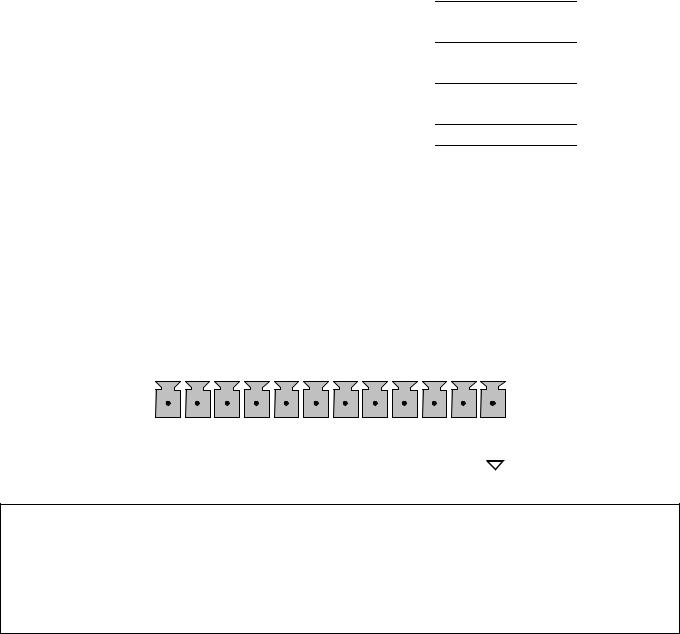
Model GFC7000E Instruction Manual |
|
|
Getting Started |
|||||||
|
|
|
Table 3-1: GFC7000E Analog Output Pin Outs |
|||||||
|
|
|
|
|
|
|
|
|
|
|
|
|
Pin |
|
Analog Output |
VDC Signal |
mADC Signal |
|
|||
|
|
|
|
|
|
|
|
|
|
|
|
1 |
|
A1 |
|
V Out |
|
I Out + |
|
||
|
2 |
|
|
|
Ground |
|
I Out - |
|
|
|
|
|
|
|
|
|
|
|
|
||
|
3 |
|
A2 |
|
V Out |
|
I Out + |
|
|
|
|
4 |
|
|
|
Ground |
|
I Out - |
|
|
|
|
|
|
|
|
|
|
|
|
||
|
5 |
|
A3 |
|
V Out |
|
I Out + |
|
|
|
|
6 |
|
|
|
Ground |
|
I Out - |
|
|
|
|
|
|
|
|
|
|
|
|
||
|
7 |
|
A4 (Spare) |
|
V Out |
|
Not Available |
|
|
|
|
8 |
|
|
|
Ground |
|
Not Available |
|
|
|
|
|
|
|
|
|
|
|
|
|
|
•The default analog output voltage setting of the GFC7000E CO2 Analyzer is 0 – 5 VDC with a range of 0 – 500 ppm.
•TO change these settings, see Sections 6.9.4 and 6.7 respectively.
10.If you wish utilize the analyzer’s status outputs to interface with a device that accepts logiclevel digital inputs, such as programmable logic controllers (PLC’s) they are accessed via a 12pin connector on the analyzer’s rear panel labeled STATUS.
STATUS
|
|
|
|
|
|
|
|
|
|
|
|
|
|
|
|
1 2 3 4 5 6 7 8 D |
+ |
|
|
|
|
|
||
|
|
|
NOTE
Most PLC’s have internal provisions for limiting the current that the input will draw from an external device. When connecting to a unit that does not have this feature, an external dropping resistor must be used to limit the current through the transistor output to less than 50mA. At 50mA, the transistor will drop approximately 1.2V from its collector to emitter.
04584 Rev A1 |
13 |
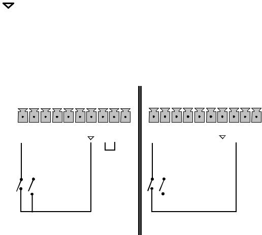
Model GFC7000E Instruction Manual |
Getting Started |
The pin assignments for the status outputs can be found in the table below:
Table 3-2: GFC7000E Status Output Pin Outs
Output # |
Status |
Condition |
||
Definition |
||||
|
|
|
||
|
|
|
|
|
1 |
|
SYSTEM OK |
On if no faults are present. |
|
|
|
|
|
|
2 |
|
CONC VALID |
On if CO2 concentration measurement is valid. |
|
|
|
If the CO2 concentration measurement is invalid, this bit is OFF. |
||
|
|
|
||
3 |
|
HIGH RANGE |
On if unit is in high range of DUAL or AUTO range modes. |
|
|
|
|
|
|
4 |
|
ZERO CAL |
On whenever the instruments ZERO point is being calibrated. |
|
|
|
|
|
|
5 |
|
SPAN CAL |
On whenever the instruments SPAN point is being calibrated. |
|
|
|
|
|
|
6 |
|
DIAG MODE |
On whenever the instrument is in DIAGNOSTIC mode. |
|
|
|
|
|
|
7 |
|
ALARM1 |
On whenever the measured CO2 concentration is above the set |
|
|
point for ALM1 |
|||
|
|
|
||
|
|
|
|
|
8 |
|
ALARM2 |
On whenever the measured CO2 concentration is above the set |
|
|
point for ALM2 |
|||
|
|
|
||
|
|
|
|
|
D |
EMITTER BUSS |
The emitters of the transistors on pins 1-8 are bussed together. |
||
|
|
|
|
|
+ |
DC POWER |
+ 5 VDC |
||
|
|
|
|
|
|
|
Digital Ground |
The ground level from the analyzer’s internal DC power supplies. |
|
|
|
|||
|
|
|||
|
|
|
|
|
11.If you wish to use the analyzer’s to remotely activate the zero and span calibration modes, several digital control inputs are provided via a 10-pin connector labeled CONTROL IN on the analyzer’s rear panel. Two methods for energizing the inputs are provided below; the first using the internal +5V available on the CONTROL IN connector and the second, if an external, isolated supply is employed.
|
CONTROL IN |
|
|
CONTROL IN |
||
|
|
|
|
|
|
|
|
|
|
|
|
|
|
|
|
|
|
|
|
|
|
|
|
|
|
|
|
|
A B C D E F |
|
U + |
|
A B C D E F |
|
U + |
||
|
|
|
|
||||||
|
|
|
|
Z |
S |
|
|
|
|
Z |
S |
|
|
|
|
|
|
||
E |
P |
|
|
|
E |
P |
|
|
|
R |
A |
|
|
|
R |
A |
|
|
|
O |
N |
|
|
|
O |
N |
|
|
|
|
|
|
|
|
|
|
|
|
|
|
- |
|
+ |
|
5 VDC Power |
||
|
|
Supply |
|
|
|
|
|
Local Power Connections |
External Power Connections |
||
04584 Rev A1 |
14 |
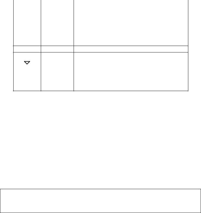
Model GFC7000E Instruction Manual |
Getting Started |
The pin assignments for the digital control inputs can be found in the table below:
|
Table 3-3: |
GFC7000E Control Input Pin Outs |
|
|
|
|
|
Input # |
Status |
On Condition |
|
Definition |
|||
|
|
||
|
|
|
|
A |
REMOTE ZERO |
The Analyzer is placed in Zero Calibration mode. The mode |
|
CAL |
field of the display will read ZERO CAL R. |
||
|
|||
|
|
|
|
B |
REMOTE |
The Analyzer is placed in Span Calibration mode. The mode |
|
SPAN CAL |
field of the display will read SPAN CAL R. |
||
|
|||
|
|
|
|
C |
SPARE |
|
|
|
|
|
|
D |
SPARE |
|
ESPARE
FSPARE
|
|
Digital Ground |
May be connected to the ground of the datalogger/recorder. |
|
|
|
|||
|
|
|
|
|
U |
Pullup supply |
Input pin for +5 VDC required to activate pins A – F. This |
||
can be from an external source or from the “+” pin of the |
||||
for inputs |
||||
|
|
instruments STATUS connector. |
||
|
|
|
||
|
|
|
|
|
+ |
Internal +5V |
Internal source of +5V which can be used to actuate control |
||
Supply |
inputs when connected to the U pin. |
|||
|
|
|||
12.If you wish to utilize either of the analyzer’s two serial interface COMM ports, refer to Section 6.10 of this manual for instructions on their configuration and usage.
13.If your unit has a Teledyne Instruments Ethernet card (Option 63), plug one end into the 7’ CAT5 cable supplied with the option into the appropriate place on the back of the analyzer (see Figure 5-4 in Section 5.5.3) and the other end into any nearby Ethernet access port.
3.1.2. Pneumatic Connections:
3.1.2.1. Basic Pneumatic Connections
Figures 3-3 and 3-4 illustrate the most common configurations for gas supply and exhaust lines to the Model GFC7000E Analyzer. Figure 3-13 illustrates the internal gas flow of the instrument in its basic configuration.
Please refer to Figure 3-2 for pneumatic connections at the rear panel and Table 3-4 for nomenclature.
NOTE
Sample and calibration gases should only come into contact with PTFE (Teflon), FEP, glass, stainless steel or brass. CAUTION
04584 Rev A1 |
15 |
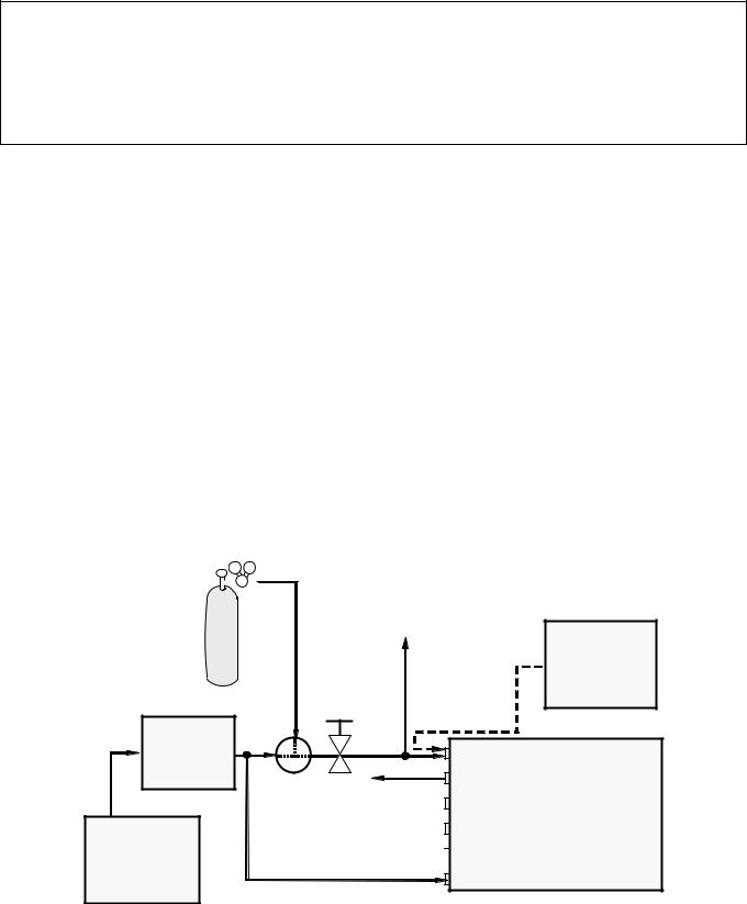
Model GFC7000E Instruction Manual |
Getting Started |
CAUTION
In order to prevent dust from getting into the gas flow channels of your analyzer, it was shipped with small plugs inserted into each of the pneumatic fittings on the back panel.
Make sure that all of these dust plugs are removed before attaching exhaust and supply gas lines.
Table 3-4: |
Model GFC7000E Rear Panel Pneumatic Connections |
|||||
|
|
|
|
|
|
|
Rear Panel Label |
|
|
|
|
|
Function |
|
|
|
|
|
|
|
|
|
|
|
Connect a gas line from the source of sample gas here. |
||
SAMPLE |
|
|
|
Calibration gasses are also inlet here on units without |
||
|
|
|
|
zero/span/shutoff valve or IZS options installed. |
||
|
|
|
|
|
|
|
EXHAUST |
|
|
|
Connect an exhaust gas line of not more than 10 meters long here. |
||
|
|
|
|
|
|
|
PRESSURE SPAN |
|
|
|
On units with zero/span/shutoff valve options installed, connect a |
||
|
|
|
gas line to the source of calibrated span gas here. |
|||
|
|
|
|
|||
|
|
|
|
|
|
|
|
|
|
|
Span gas vent outlet for units with zero/span/shutoff valve options |
||
VENT SPAN |
|
|
|
installed. |
||
|
|
|
|
Connect an exhaust gas line of not more than 10 meters long here. |
||
|
|
|
|
|
|
|
|
|
|
|
Internal zero air scrubber. |
||
IZS |
|
|
|
on units with zero/span/shutoff valve options installed but NO |
||
|
|
|
internal zero air scrubber, attach a gas line to the source of zero air |
|||
|
|
|
|
|||
|
|
|
|
here. |
||
|
|
|
|
|
|
|
|
|
|
|
This inlet supplies purge air to the GFC wheel housing (see section |
||
PURGE IN |
|
10.2.2) |
||||
|
|
|
|
Connect a source of dried air that has been scrubbed of CO2. |
||
|
|
|
|
|
|
|
Calibrated CO2 |
|
VENT |
|
gas at desired |
|
Source of |
|
|
|
||
span gas |
|
|
|
|
|
SAMPLE Gas |
|
concentration |
Needle |
|
|
|
Removed |
||
|
|
||
|
valve to |
|
during |
|
control |
|
Calibration |
|
flow |
|
|
Indicating |
|
Sample |
|
soda-lime |
|
MODEL |
|
|
Valve |
Exhaust |
|
|
|
Vent Span |
GFC7000E |
|
|
|
|
|
|
Pressure Span |
|
MODEL 701
Zero Air  IZS
IZS
Generator
Purge In
Figure 3-3: Pneumatic Connections–Basic Configuration–Using Bottled Span Gas
04584 Rev A1 |
16 |
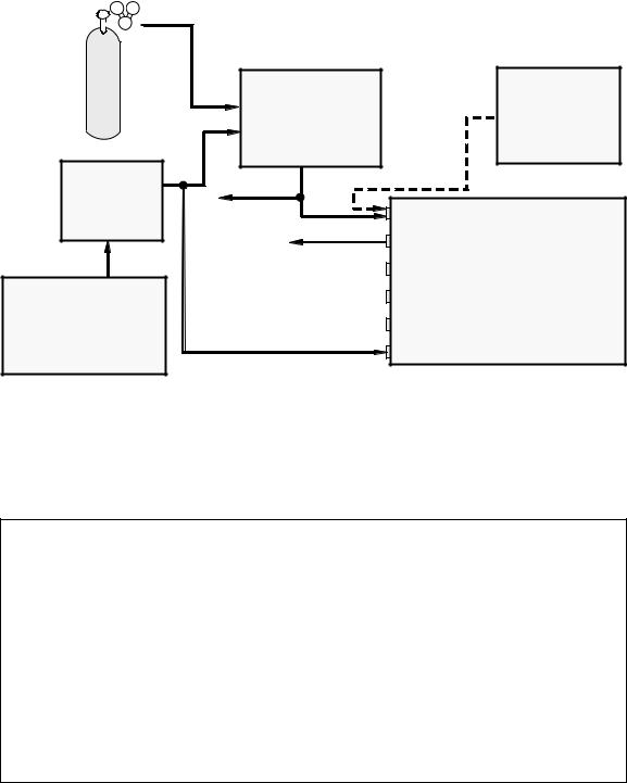
Model GFC7000E Instruction Manual |
Getting Started |
||||
|
|
|
|
|
|
Calibrated |
|
|
Source of |
MODEL 700 |
|
SAMPLE Gas |
|
CO2 Gas |
|
||
|
Gas Dilution |
|
Removed |
|
Calibrator |
|
during |
|
|
|
Calibration |
Indicating |
|
|
|
soda-lime |
VENT |
Sample |
|
|
|
MODEL |
|
|
|
Exhaust |
|
|
|
GFC7000E |
|
|
|
Vent Span |
|
|
|
|
|
MODEL 701 |
|
Pressure Span |
|
|
|
|
|
Zero Air Generator |
|
IZS |
|
|
|
Purge In |
|
Figure 3-4: Pneumatic Connections–Basic Configuration–Using Gas Dilution Calibrator
1.Attach a sample inlet line to the sample inlet port. The SAMPLE input line should not be more than 2 meters long.
NOTE
Ideally, the pressure of the sample gas should be at ambient pressure (0 psig). Maximum pressure of sample gas should not exceed 1.5 in-Hg over ambient.
In applications where the sample gas is received from a pressurized manifold, a vent must be placed as shown to equalize the sample gas with ambient atmospheric pressure before it enters the analyzer.
This vent line must be:
•At least 0.2m long
•No more than 2m long and vented outside the shelter or immediate area surrounding the instrument.
04584 Rev A1 |
17 |

Model GFC7000E Instruction Manual |
Getting Started |
2.Attach sources of zero air and span gas (see Figures 3-3 through 3-8 inclusive).
•Span Gas is a gas specifically mixed to match the chemical composition of the type of gas being measured at near full scale of the desired measurement range.
In the case of CO2 measurements made with the Teledyne Analytical Instruments Model GFC7000E Analyzer it is recommended that you use a gas calibrated to have a CO2 content equaling 80% of the range of compositions being measured.
EXAMPLE: If the application is to measure between 0 ppm and 500 ppm, an appropriate Span Gas would be 400 ppm. If the application is to measure between 0 ppm and 100 ppm, an appropriate Span Gas would be 80 ppm.
•Span Gas can be purchased in pressurized canisters or created using Dynamic Dilution Calibrator such as the Teledyne Analytical Instruments Model 700 and a source of dried
air scrubbed of CO2 such as a Teledyne Analytical Instruments Model 701 Zero Air Generator in combination with a canister of indicating soda-lime.
•Zero Air is similar in chemical composition to the earths atmosphere but scrubbed of all components that might affect the analyzer’s readings.
In the case of CO2 measurements this means CO2 less than 0.1 ppm of CO2 and Water Vapor. Zero Air can be purchased in pressurized canisters or created using a Teledyne Instruments Model 701 Zero Air Generator in combination with a canister of indicating soda-lime.
3.Attach an exhaust line to the exhaust outlet port.
•The exhaust from the pump and vent lines should be vented to atmospheric pressure using maximum of 10 meters of ¼” PTEF tubing.
CAUTION
Venting should be outside the shelter or immediate area surrounding the instrument.
4. Attach a source of dried air scrubbed of CO2 to the purge inlet port
NOTE
The source of purge air should be at 20-25 psig and capable of maintaining a flow of at least 0.5 liters/min.
Purge source air pressure should not exceed 35 pisg
5.Once the appropriate pneumatic connections have been made, check all pneumatic fittings for leaks using a procedure similar to that defined in Section 9.3.3.
04584 Rev A1 |
18 |
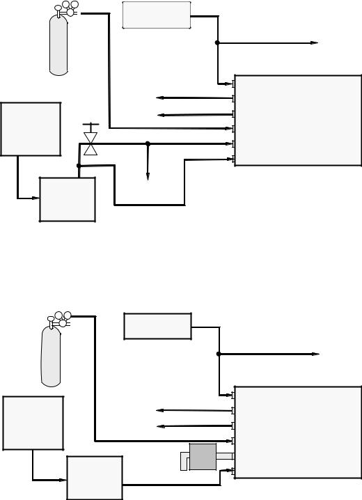
Model GFC7000E Instruction Manual |
Getting Started |
3.1.2.2. Connections with Internal Valve Options Installed
Figures 3-5 through 3-8 show the proper pneumatic connections for MGFC7000E’s with various optional internal valve sets installed.
Source of
SAMPLE Gas
VENT if input is pressurized
Certified |
|
|
|
|
|
CO2 Gas |
|
|
|
|
|
|
|
|
|
Sample |
|
|
Needle |
|
|
Exhaust |
MODEL |
|
valve to |
|
|
||
|
control |
|
VENT |
|
GFC7000E |
MODEL 701 |
flow |
|
Vent Span |
||
|
|
||||
|
|
|
|
||
Zero Air |
|
|
|
Pressure Span |
|
Generator |
|
|
|
|
|
|
|
VENT |
|
IZS |
|
|
|
|
|
|
|
|
|
|
|
Purge In |
|
Indicating
soda-lime
Figure 3-5: Pneumatic Connections–MGFC7000E with Zero/Span/Shutoff Valves (OPT 50)
|
Source of |
|
|
|
SAMPLE Gas |
|
|
|
|
VENT if input is pressurized |
|
Certified |
|
|
|
CO2 Gas |
|
|
|
|
|
Sample |
MODEL |
MODEL 701 |
|
Exhaust |
|
|
|
|
|
Zero Air |
VENT |
Vent Span |
GFC7000E |
Generator |
|||
|
|
Pressure Span |
|
|
External Zero |
IZS |
|
|
Air Scrubber |
|
|
|
Indicating |
Purge In |
|
|
soda-lime |
|
|
Figure 3-6 Pneumatic Connections–MGFC7000E with Zero/Span/Shutoff Valves and External Zero Air Scrubber (OPT 51)
04584 Rev A1 |
19 |
 Loading...