


102E
Table of contents
 Loading...
ADDENDUM TO
MODEL 101E
OPERATORS MANUAL
(P/N 04740 REV. A)
FOR
MODEL 102E
TOTAL REDUCED SULFUR ANALYZER
with
MODEL 501 TRS
THERMAL CONVERTER
© TELEDYNE ADVANCED POLLUTION INSTRUMENTATION
9480 CARROLL PARK DRIVE
SAN DIEGO, CA 92121-5201
USA
Toll-free Phone: 800-324-5190
Phone: 858-657-9800
Fax: 858-657-9816
Email: Api-sales@teledyne.com
Website:
http://www.teledyne-api.com/
04988
REV. A1
© 2005 T-API 18 October 2005


M102E/M501 TRS
(Addendum to M101E Manual - P/N 04740 Rev A)
TABLE OF CONTENTS
1. PREFACE ...................................................................................................................................... 1
1.1. Reference Numbering convention...............................................................................................2
2. SPECIFICATIONS, APPROVALS AND WARRANTY.......................................................................... 3
2.1. Specifications..........................................................................................................................3
2.1.1. M501-TRS Specifications ....................................................................................................3
2.2. EPA Equivalency Designation.....................................................................................................3
2.3. CE Mark Compliance ................................................................................................................4
3. GETTING STARTED....................................................................................................................... 5
3.1. Unpacking the M102E ..............................................................................................................5
3.2. Unpacking the M501-TRS .........................................................................................................5
3.2.1. M501-TRS Ventilation Clearance: ........................................................................................6
3.3. Internal Layouts......................................................................................................................7
3.4. Internal Pneumatic Flow of the M102E & the M501-TRS ................................................................8
3.5. Rear Panel Layout for the M102E & M501-TRS .............................................................................9
3.6. Initial Setup .........................................................................................................................10
3.6.1. Electrical Connections:..................................................................................................... 10
3.6.1.1. M102E Analog Output Connections.............................................................................. 10
3.6.1.2. M501-TRS Alarm Output Connections .......................................................................... 11
3.6.2. Pneumatic Connections:...................................................................................................11
3.6.2.1. Connections with Internal Valve Options Installed..........................................................14
3.7. Initial Operation ....................................................................................................................17
3.7.1. Startup / Warm Up of the M102E.......................................................................................17
3.7.2. Functional Check of the M102E..........................................................................................17
3.7.3. Startup / Warm Up of the M501-TRS..................................................................................18
3.8. Initial Calibration...................................................................................................................19
4. OPTIONAL HARDWARE AND SOFTWARE .................................................................................... 21
4.1. Rack Mount Kits (Options 20a, 20b, 21, 22 & 81)....................................................................... 21
4.2. Calibration Valves Options ......................................................................................................21
4.2.1. Zero/Span Valves (Option 50) & Internal Zero/Span Gas Generator (Option 51)....................... 21
4.3. Additional Manuals.................................................................................................................24
4.3.1. Printed Manuals (P/N 049880000) ..................................................................................... 24
4.3.2. Addendum on CD (Part number 049880200) ....................................................................... 24
5. M102E OPERATING INSTRUCTIONS........................................................................................... 25
5.1.1. M102E Analog Output Signals ........................................................................................... 25
5.1.2. Setting the M102E Gas Measurement Mode......................................................................... 26
5.2. SETUP – DIAG: Using the Diagnostics Functions......................................................................... 26
5.2.1. M102E Analog I/O Configuration........................................................................................26
5.2.2. M102E Test Channel Output .............................................................................................27
5.3. SETUP – COMM: Setting Up the M102E’s Communication Ports ....................................................27
5.3.1. M102E ID Code............................................................................................................... 27
5.3.2. M102E Ethernet Host Name .............................................................................................. 27
5.4. Remote Operation of the Analyzer............................................................................................28
5.4.1. Control Inputs ................................................................................................................28
5.4.2. Using the M102E with a Hessen Protocol Network ................................................................29
5.4.2.1. M102E Hessen Protocol Gas ID List. ............................................................................29
5.4.2.2. Setting Hessen Protocol Status Flags ...........................................................................30
6. M501-TRS OPERATING INSTRUCTIONS ..................................................................................... 31
6.1. Basic M501-TRS Controls........................................................................................................ 31
6.2. To Display The Current Temperature:....................................................................................... 32
6.3. To Manually Adjust the Converter Oven Temperature: ................................................................ 33
6.4. Autotune the Temperature Controller: ......................................................................................34
6.4.1. Initiating the Autotune Process: ........................................................................................34
6.4.2. Aborting the Autotune Process:.........................................................................................35
6.5. M501TRS Alarm Relay Adjustment ...........................................................................................35
7. CALIBRATION PROCEDURES...................................................................................................... 37
7.1. M102E Calibration .................................................................................................................37
7.2. M501-TRS Calibration ............................................................................................................37
05514 Rev A1 i

M102E/M501 TRS
(Addendum to M101E Manual - P/N 04740 Rev A)
8. INSTRUMENT MAINTENANCE..................................................................................................... 39
8.1. Additional and Updated Maintenance Procedures........................................................................40
8.1.1. Maintaining the SO
8.1.1.1. Predicting When the SO
8.1.1.2. Checking the Function of the SO
8.1.1.3. Changing the SO
9. THEORY OF OPERATION............................................................................................................. 43
9.1. Measurement Principle ...........................................................................................................43
9.1.1. TRS Conversion ..............................................................................................................43
9.1.2. SO
Ultraviolet Fluorescence ............................................................................................. 43
2
9.2. The UV Light Path..................................................................................................................46
9.2.1. UV Lamp Shutter & PMT Offset.......................................................................................... 46
9.3. Pneumatic Operation..............................................................................................................46
9.3.1. Sample gas Flow.............................................................................................................46
9.3.2. M501 SO
Scrubber ......................................................................................................... 46
2
9.4. Electronic Operation...............................................................................................................47
9.4.1. Sensor Module................................................................................................................ 47
9.4.1.1. Sample Chamber......................................................................................................48
9.4.1.2. Sample Chamber Heating Circuit.................................................................................48
9.4.2. M501-TRS electronics ......................................................................................................49
9.4.2.1. Thermal Switch ........................................................................................................49
9.4.2.2. Temperature Alarms and Alarm Output ........................................................................ 50
10. TROUBLESHOOTING & REPAIR ................................................................................................ 51
10.1.1. Fault Diagnosis with Warning Messages ............................................................................ 51
10.1.1.1. M102E Warning Messages ........................................................................................ 51
10.1.1.2. M501-TRS Error Codes.............................................................................................51
10.1.2. Fault Diagnosis with Test Functions.................................................................................. 52
10.2. M501-TRS Trouble shooting ..................................................................................................53
10.2.1. TRS Converter Not Heating:............................................................................................ 53
10.3. Other Performance Problems ................................................................................................. 53
10.3.1. Excessive noise.............................................................................................................53
10.4. Subsystem Checkout............................................................................................................ 54
10.4.1. Checking the Efficiency of the M501-TRS SO
10.4.2. Checking the Efficiency of the M501-TRS TRS Æ SO
10.5. Additional Repair Procedures ................................................................................................. 55
10.5.1. UV Lamp Adjustment and/or Replacement ........................................................................55
10.5.1.1. Adjusting the UV Lamp (Peaking the Lamp) ................................................................56
10.5.1.2. Replacing the UV Lamp............................................................................................57
10.5.2. Replacing the UV filter/lens .............................................................................................. 58
10.5.3. Replacing the PMT, HVPS or TEC......................................................................................59
10.5.4. M102E PMT Hardware Calibration (FACTORY CAL) .............................................................. 61
10.5.5. Replacing the TRS Converter Heating Tube .......................................................................63
10.6. Manually Programming the M501-TRS Temperature Controller ...................................................64
10.6.1. Temperature Controller Primary Menu Parameters..............................................................65
10.7. Technical Assistance ............................................................................................................67
Scrubber ...........................................................................................40
2
Scrubber Material ............................................................................ 41
2
Scrubber Should Be Replaced. ................................................. 40
2
Scrubber................................................................... 41
2
Scrubber....................................................... 54
2
Converter............................................ 54
2
LIST OF APPENDICES
APPENDIX A - VERSION SPECIFIC SOFTWARE DOCUMENTATION
APPENDIX A-1: M102E Software Menu Trees, Revision A.2
APPENDIX A-2: Setup Variables For Serial I/O, Revision A.2
APPENDIX A-3: Warnings and Test Functions, Revision A.2
APPENDIX A-4: M102E Signal I/O Definitions, Revision A.2
APPENDIX A-5: M102E iDAS Functions, Revision A.2
APPENDIX B - M102E SPARE PARTS LIST
APPENDIX D - ELECTRONIC SCHEMATICS
ii 05514 Rev A1

M102E/M501 TRS PREFACE
(Addendum to M101E Manual - P/N 04740 Rev A)
LIST OF FIGURES
Figure 3-1: M102E Internal Layout ...................................................................................7
Figure 3-2: M501-TRS Internal Layout...............................................................................7
Figure 3-3: Internal Pneumatic Diagram of the M102E Standard Configuration........................ 8
Figure 3-4: M102E Rear Panel Layout................................................................................9
Figure 3-5: M501-TRS Rear Panel Layout...........................................................................9
Figure 3-6: Analog Output Connector .............................................................................. 10
Figure 3-7: Pneumatic Connections–Basic Configuration–Using Gas Dilution Calibrator ........... 12
Figure 3-8: Pneumatic Connections–Basic Configuration–Using Bottled Span Gas .................. 12
Figure 3-9: Basic Pneumatic Connections for Units with Zero/Span Valve Option ................... 15
Figure 3-10: Pneumatic Connections for Formal Calibration of Units with an IZS Valve Option ... 16
Figure 3-11: Pneumatic Connections for Informal Calibration Checks of Units with IZS Valve
Option ...................................................................................................... 16
Figure 3-12: M501-TRS Temperature Controller Startup ..................................................... 18
Figure 4-1: Internal Pneumatic Diagram of the M102E With Z/S Option Installed................... 22
Figure 4-2: Internal Pneumatic Diagram of the M102E with IZS Options Installed.................. 23
Figure 5-1: Analog Output Connector Key ........................................................................ 25
Figure 5-2: Control Inputs with local 5 V power supply ...................................................... 28
Figure 5-3: Control Inputs with external 5 V power supply ................................................. 29
Figure 6–1: M501-TRS Temperature Controls ................................................................... 31
Figure 9-1: UV Absorption in the M102E Reaction Cell ....................................................... 44
Figure 9-2: M102E Sensor Module .................................................................................. 47
Figure 9-3: M102E Sample Chamber............................................................................... 48
Figure 9-4: M501-TRS Electronic Block Diagram ............................................................... 49
Figure 10-1: Shutter Assembly - Exploded View.................................................................. 57
Figure 10-2: Disassembling the Shutter Assembly............................................................... 58
Figure 10-3: PMT Assembly - Exploded View ...................................................................... 59
Figure 10-4: Pre-Amplifier Board Layout............................................................................ 62
LIST OF TABLES
Table 2-1: Model 102E Basic Unit Specifications..................................................................3
Table 3-1: TRS – SO
Table 3–2: Analog output Pin Outs................................................................................... 10
Table 3-3: Inlet / Outlet Connector Nomenclature............................................................. 11
Table 3-4: NIST-SRM's Available for Traceability of H2S & SO
Table 4-1: Zero/Span Valve Operating States.................................................................. 22
Table 4-2: IZS Valve Operating States ........................................................................... 23
Table 5-1 M102E gas Measurement Modes...................................................................... 26
Table 5-2: Analog Output Pin Assignments ....................................................................... 26
Table 5-3: Test Parameters Available for Analog Output A4 ................................................ 27
Table 5-4: M102E Control Input Pin Assignments .............................................................. 28
Table 5-5: M102E Default Hessen Gas ID’s....................................................................... 29
Table 5-6: Default Hessen Status Bit Assignments ............................................................ 30
Table 6-1: M501-TRS Temperature Controls and Definitions ............................................... 32
Table 8-1: M102E Preventive Maintenance Schedule.......................................................... 39
Table 10-1: Test Functions - Possible Causes for Out-Of-Range Values ................................... 51
Table 10-2: Test Functions - Possible Causes for Out-Of-Range Values ................................... 52
Table 10-3 – Temperature Controller – Primary Parameter Settings......................................... 66
Table 10-4 – Temperature Controller – Primary Parameter Settings......................................... 67
Switching Valve Operating Modes....................................................... 8
2
Calibration Gases .................... 14
2
05514 Rev A1 iii


M102E/M501 TRS PREFACE
(Addendum to M101E Manual - P/N 04740 Rev A)
1. PREFACE
NOTE
The information contained in this addendum is pertinent to M102E analyzers running
software revision A.2. Some or all of the information may not be applicable to previous
revision of that software.
The software revision your analyzer is running is displayed in the upper left-hand
corner of the display any time the instrument is in SETUP mode.
This addendum is based on the Model 101E Operators Manual (P/N 04740, REV. A). In most ways
the M102E is identical to the M102E in design and operation, therefore most of the basic set up
information, operating instructions as well as calibration, maintenance, troubleshooting and repair
methods are found in that manual.
This addendum documents only those areas where the M102E is different in design or operating
method from the M102E.
Specifically:
• Areas where updates and improvements to the M10XE software have been implemented
since the publication date of the M101E Manual - P/N 04740 Rev A.
• Corrections of errors and omissions discovered in the M101E Manual - P/N 04740 Rev A.
• EXTERNAL TRS CONVERSION: Like the M101E, which converts H
measures the amount of SO
converts total reduced sulfur (TRS) gases into SO
present using a UV fluorescence technique, the M102E
2
before measuring the SO2 using the
2
S to SO2, then
2
same UV fluorescence method.
Unlike the M102E, which performs the H
S Æ SO2 conversion internally, the M102E
2
requires an external TRS converter, in this case a Teledyne Instruments M501-TRS.
Therefore this addendum includes instructions and information regarding:
• Areas of operation and setup of the M102 that depart from the method described by
the M101E operator’s manual because the TRS Æ SO
conversion is performed
2
externally.
• The proper set up and operation on the M501-TRS.
05514 Rev A1 1

PREFACE M102E/M501 TRS
(Addendum to M101E Manual - P/N 04740 Rev A)
1.1. Reference Numbering convention
Unless otherwise specified, chapter, section, figure and table reference numbers referred to within
this text are relative to this document.
EXAMPLE: “Figure 2-1” refers to the figure, within this document, labeled as 2-1.
References to chapters, sections, figures and tables in the original document will be labeled as
such.
EXAMPLE: “Figure 6.1 of the M101E Operators Manual (P/N 04470, REV. A)”.
User Notes:
2 05514 Rev A1

M102E/M501 TRS SPECIFICATIONS, APPROVALS AND WARRANTY
(Addendum to M101E Manual - P/N 04740 Rev A)
2. SPECIFICATIONS, APPROVALS AND
WARRANTY
2.1. Specifications
There are no significant differences between the performance specifications for the M102E and the
M102E as listed in Section 2.1 of the M101E Manual - P/N 04740 Rev A.
2.1.1. M501-TRS Specifications
Table 2-1: Model 102E Basic Unit Specifications
S >95%
H
Minimum Converter Efficiency
Maximum TS Concentration for
specified conversion efficiency
Sample Flow Rate 650cc/min. ±10% - driven by M102E pneumatic system
Optimum Converter
Temperature
Maximum Converter
Temperature
Dimensions H x W x D 7" x 17" x 22" (178 mm x 432 mm x 559 mm)
Weight
AC Power Rating
Internal Alarms
Alarm Output Relay
Alarm Output Rating
Environmental Installation category (over-voltage category) II; Pollution degree 2
Certifications
For indoor use at altitudes ≤ 2000m only
2
COS >90%
CS
>90%
2
20 ppmv
1000°C (factory setup)
1100°C
16 lbs (8 kg)
26 lbs (12 kg) CE version
115 V, 50/60 Hz - 400 Watts;
230 V, 50/60 Hz - 575 Watts; CE Version
High Alarm Point: 1050°C
Low Alarm Point: 950°C
SPST - 1 point: Alarm output is energized should either the temperature
controller’s high or low internal alarm set points be activated.
220V AC/30V DC, 1A (resistive load)
IEC 1010-1 / 61010-1:93 (includes A1) + A2:95,
2.2. EPA Equivalency Designation
No EPA equivalency standards exist for TRS measurement, however, the M102E analyzer qualifies
for EPA equivalency designation as Reference Method Number EQSA-0495-100 per 40 CFR Part 53
when operated under the following conditions:
• Measurement Mode: SO2 single gas mode.
• Range: Any range from 50 parts per billion (ppb) to 10 parts per million (ppm).
o
• Ambient temperature range of 5
• Line voltage range of 105-125 VAC or 220-240 VAC, at 50 or 60 Hz.
05514 Rev A1 3
C to 40 oC.

SPECIFICATIONS, APPROVALS AND WARRANTY M102E/M501 TRS
(Addendum to M101E Manual - P/N 04740 Rev A)
• Sample filter: Equipped with PTFE filter element in the internal filter assembly.
• Sample flow of 650 +/- 65 cc/min.
• Vacuum pump (internal or external) capable of 14"Hg Absolute pressure @ 1 slpm or
better.
• Software settings:
Dynamic span OFF
Dynamic zero OFF
Dilution factor OFF
AutoCal ON or OFF
Dual range ON or OFF
Auto-range ON or OFF
Temp/Pressure compensation ON
Under the designation, the analyzer may be operated with or without the following optional
equipment:
• Rack mount with chassis slides.
• Rack mount without slides, ears only.
• Zero/span valve options.
• Internal zero/span (IZS) option with either:
• SO
• SO
• 4-20mA isolated analog outputs.
• Status outputs.
• Control inputs.
• RS-232 output.
• Ethernet output.
• Zero air scrubber.
• 4-20mA, isolated output.
permeation tube - 0.4 ppm at 0.7 liter per minute; certified/uncertified.
2
permeation tube - 0.8 ppm at 0.7 liter per minute; certified/uncertified. Under the
2
designation, the IZS option cannot be used as the source of calibration.
2.3. CE Mark Compliance
See Section 2.3 of the M101E Manual - P/N 04740 Rev A
User Notes:
4 05514 Rev A1
M102E/M501 TRS GETTING STARTED
(Addendum to M101E Manual - P/N 04740 Rev A)
3. GETTING STARTED
3.1. Unpacking the M102E
Unpack the M102E as per the directions ins Section 3.1 of the M101E Manual - P/N 04740 Rev A.
1. There are no shipping screws to be removed in the M102E.
3.2. Unpacking the M501-TRS
2. Inspect the shipping package for external damage. If damaged, please advise the shipper first,
then Teledyne Instruments.
3. Carefully remove the top cover of the converter and check for internal shipping damage.
• Remove the screws fastening the top cover to the unit (four per side).
• Lift the cover straight up.
CAUTION
Never disconnect electronic circuit boards, wiring harnesses or
4. Inspect the interior of the instrument to make sure all components are in good shape and
properly seated.
5. Check the connectors of the various internal wiring harnesses and pneumatic hoses to make
sure they are firmly and properly seated.
6. There are no shipping screws to be removed in the M501-TRS.
7. Replace the top cover.
The M501-TRS will not operate properly with the top cover removed.
electronic subassemblies while the unit is under power.
NOTE
The air cooling required to stabilize the temperature of the converter tube is dependent
on air flow patterns that only exist with the top cover in place.
Without the top cover in place, the thermal cutout may overheat and shut off the
heating element.
05514 Rev A1 5

GETTING STARTED M102E/M501 TRS
(Addendum to M101E Manual - P/N 04740 Rev A)
3.2.1. M501-TRS Ventilation Clearance:
Whether the M501-TRS is set up on a bench or installed into an instrument rack, be sure to leave
sufficient ventilation clearance.
AREA MINIMUM REQUIRED CLEARANCE
Back of the instrument 10 cm / 4 inches
Sides of the instrument 2.5 cm / 1 inch
Above and below the instrument. 2.5 cm / 1 inch
NOTE
If the M501-TRS is installed in an instrument rack or any type of enclosure, make sure
that the rack/enclosure itself is adequately ventilated.
Failure to provide proper ventilation can result in the ambient temperature exceeding
the maximum operating temperature specification for the M102E (40°C)
6 05514 Rev A1

M102E/M501 TRS GETTING STARTED
g
g Sy
/
y
(Addendum to M101E Manual - P/N 04740 Rev A)
3.3. Internal Layouts
Figures 3-1 & 3-3 supersede Figure 3-9 of the M101E Manual - P/N 04740 Rev A.
Front Panel
Reaction Cell
Hydrocarbon Scrubber
Hidden from view b eneath
Reaction Cell
ON/OFF
SWITCH
Particulate Filter
Pump Assy
UV Source Lap
230VAC
Transformer
(Option)
PMT Preamp PCA
PMT Housin
Rela
PMT Coolin
Board
IZS Permeation Tube and Oven
(+12 VDC)
stem
PS2
(Option)
Span/Cal Valves
PS1
(+5 VDC; ±15VDC)
(Option)
PC
104 Card
Rear Panel
Mother
Board
Vacuum
Manifold
Power Supply
UV Lamp
ON/OFF
SWITCH
Figure 3-1: M102E Internal Layout
Temperature
Controller
230VAC
Transformer
(Option)
Converter Tube Cover
Converter Heater located
underneath Cover
SO2
Scrubber
Converter Tube
Converter Heater
Control Relay
Alarm
Outputs
Figure 3-2: M501-TRS Internal Layout
05514 Rev A1 7
GETTING STARTED M102E/M501 TRS
R
R
A
(Addendum to M101E Manual - P/N 04740 Rev A)
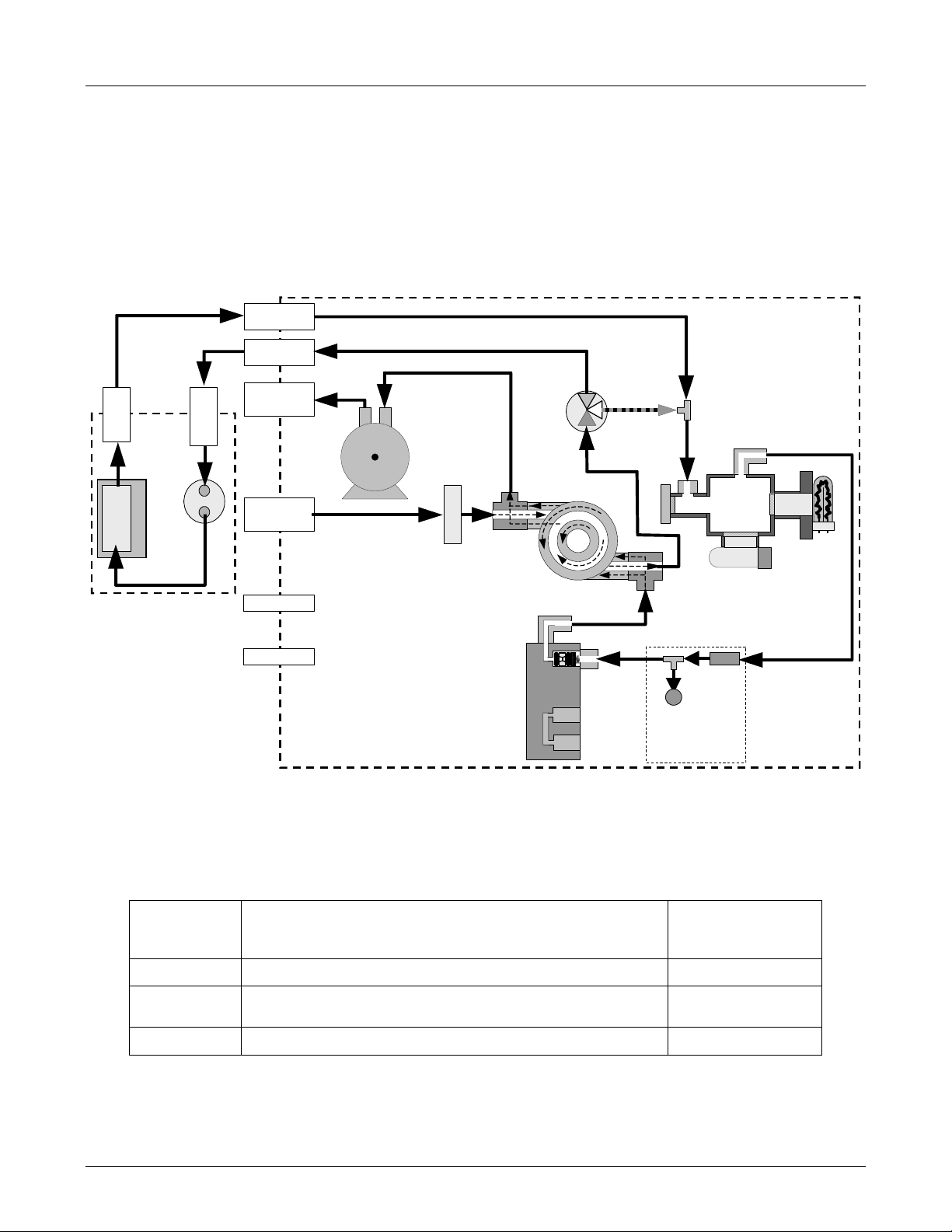
3.4. Internal Pneumatic Flow of the M102E & the
M501-TRS
Figure 3-3 shows the internal pneumatic flow of the M102E in its Standard configuration. For
information on instruments in which one of the various zero/span valve options refer to Figures 52 and 5-3.
TO
ANALYZER
2
SO
Æ
TRS
CONVERTER OVEN
SO
FROM
ANALYZER
r
2
Scrubbe
FROM
CONVERTER
TO
CONVERTER
EXHAUST GAS
OUTLET
SAMPLE GAS
INLET
INSTRUMENT
M102E
CHASSIS
KICKER EXHAUST
PUMP
SAMPLE FILTER
TO PUMP
TRS / SO
2
MODE
VALVE
HYDROCARBON
SCRUBBER
(KICKER)
Gas Flow in SO
3
1
2
phase
2
of multigas mode or
when i n SO
2
measurement mode
SAMPLE
CHAMBER
PMT
UV
LAMP
M501-TRS
ZERO AIR INLET
SPAN GAS INLET
VACUUM MANIFOLD
EXHAUST TO OUTE
LAYER OF KICKE
FLOW
CONTROL
ASSY
SAMPLE
PRESSURE
SENSOR
FLOW / PRESSURE
SENSOR PC
FLOW
SENSOR
Figure 3-3: Internal Pneumatic Diagram of the M102E Standard Con figuration.
Switching Valve Operating Modes
2
Bypasses M501-TRS
CONNECTION
(FIG. 5-2)
2 Æ 3
2 Æ 1
- -
GAS
MODE
TRS
SO2
TRS –SO2
Table 3-1: TRS – SO
CONDITION OF TRS –SO2 SWITCHING VALVE VALVE PORT
Open to SO
Switches between above two states every 10 minutes.
Scrubber and Molybdenum Converter
2
Open to directly to Sample Chamber.
8 05514 Rev A1
M102E/M501 TRS GETTING STARTED
(Addendum to M101E Manual - P/N 04740 Rev A)
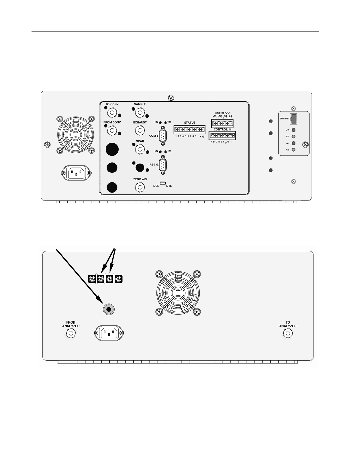
3.5. Rear Panel Layout for the M102E & M501-TRS
Figures 3-4 & 3-5 supersede Figure 3-2 of the M101E Manual - P/N 04740 Rev A.
5 Amp
Slow-Blow
Fuse
Figure 3-4: M102E Rear Panel Layout
Alarm Output
Connections
Figure 3-5: M501-TRS Rear Panel Layout
05514 Rev A1 9
GETTING STARTED M102E/M501 TRS
(Addendum to M101E Manual - P/N 04740 Rev A)
3.6. Initial Setup
3.6.1. Electrical Connections:
The electrical connections for the M102E are the same as those described in Section 3.1.1 of the
M101E Manual - P/N 04740 Rev A except for the test channel analog output:
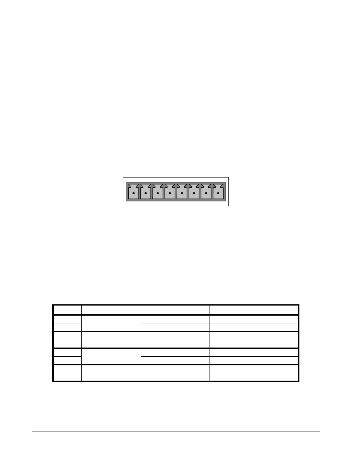
3.6.1.1. M102E Analog Output Connections
This section supercedes Section 3.1.1.1 of the M101E Manual - P/N 04740 Rev A.
Attach a strip chart recorder and/or data-logger to the appropriate contacts of the analog output
connecter on the rear panel of the analyzer.
A1 A2 A3 A4
+ - + - + - + -
ANALOG OUT
Figure 3-6: Analog Output Connector
The A1 and A2 channels output a signal that is proportional to the SO
concentration of the
2
sample gas.
The output, labeled A3 is special. It can be set by the user (see Section 6.9.10 of the M101E
Manual - P/N 04740 Rev A) to output any one of the parameters accessible through the <TST
TST> keys of the units sample display.
Pin-outs for the Analog Output connector at the rear panel of the instrument are:
Table 3–2: Analog output Pin Outs
PIN ANALOG OUTPUT VOLTAGE OUTPUT CURRENT LOOP OPTION
1 V Out I Out +
2
3 V Out I Out +
4
5 V Out I Out +
6
7 Not Available Not Available
8
A1
A2
A3
A4
Ground I Out -
Ground I Out -
Ground I Out -
Not Available Not Available
• The default analog output voltage setting of the M102E UV Fluorescence SO
Analyzer is 0
2
– 5 VDC with a range of 0 – 500 ppb.
10 05514 Rev A1

M102E/M501 TRS GETTING STARTED
(Addendum to M101E Manual - P/N 04740 Rev A)
• TO change these settings, see Sections 6.9.4 and 6.7 of the M101E Manual - P/N 04740
Rev A respectively.
3.6.1.2. M501-TRS Alarm Output Connections
The rear panel of the M501-TRS includes a terminal strip by which connections can be made to
the converters internal temperature alarm for more information on this alarm see Section 6.5).
• Connect the input leads to your alarm-sensing device (e.g. datalogger) to the center two
pins of the alarm output connector (see Figure 3-5).
• Make sure the load does not exceed the rated capacity of the relay.
3.6.2. Pneumatic Connections:
This section supercedes the information contained in Section 3.1.2 of the M101E Manual
- P/N 04740 Rev A.
CAUTION
To prevent dust from getting into the analyzer, it was shipped with small plugs inserted
into each of the pneumatic fittings on the rear panel. Make sure that all dust plugs are
removed before attaching exhaust and supply gas lines.
Sample and calibration gases should only come into contact with PTFE (Teflon) or glass materials.
They should not come in contact with FEP or stainless steel materials.
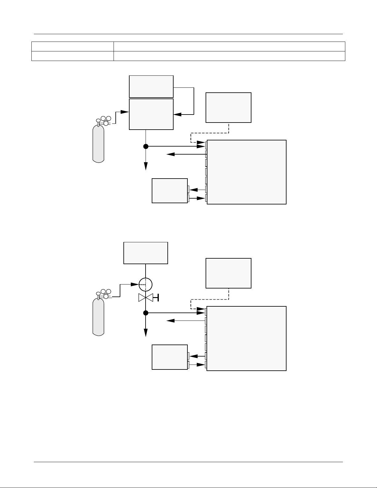
Figures 3-7 and 3-8 show the most common configurations for gas supply and exhaust lines to the
Model 102E Analyzer. Figures 3-9, 3-10 & 3-11 show the connections for units with valve options
installed.
Please refer to Figures 3-1 & 3.3 for the location of pneumatic connections at the rear panel of the
M102E and the M501-TRS.
Table 3-3: Inlet / Outlet Connector Nomenclature
M102E PNEMATIC CONNECTERS
REAR PANEL LABEL FUNCTION
SAMPLE
EXHAUST
SPAN
ZERO AIR
TO CONVERTER Sample gas leaves the M102E to be conditioned by the M501-TRS via this port.
FROM CONVERTER
Connects the sample gas to the analyzer. When operating the analyzer without
zero/span option, this is also the inlet for any calibration gases.
Exhausts the gas sampled by the analyzer. Connect to an outside area away
from people.
On units with zero/span/shutoff valve options installed, connect a gas line to
the source of calibrated span gas here.
On Units with zero/span valve or IZS option installed, this port connects the
zero air gas or the zero air cartridge to the analyzer.
Sample gas returns to the M102E after being conditioned by the M501-TRS via
this port.
M501-TRS PNEMATIC CONNECTERS
REAR PANEL LABEL FUNCTION
05514 Rev A1 11
GETTING STARTED M102E/M501 TRS
(Addendum to M101E Manual - P/N 04740 Rev A)
FROM ANALYZER Sample gas enters the M501-TRS from the M102E via this port.
TO ANALYZER Sample gas leaves the M501-TRS to return to the M102E via this port.
Calibrated
span GAS
(At high
concentration)
MODEL 701
Zero Air
Generator
MODEL 700
Gas Dilutio n
Calibrator
(with Ozone
Bench Option)
VENT
M501-TRS
From Analyzer
To Analyzer
Source of
SAMPLE Gas
Removed
Calibration
Sample
Exhaust
Span
Zero Air
To Converter
From Converter
during
MODEL
102E
Figure 3-7: Pneumatic Connections–Basic Configuration–Using Gas Dilution Calibrator
MODEL 701
Zero Air
Calibrated
span GAS
Generator
Valve
Needle
valve to
control
flow
VENT
Source of
SAMPLE Gas
Removed
during
Calibration
Sample
Exhaust
Span
MODEL
102E
M501-TRS
From Analyzer
To Analyzer
Zero Air
To Converter
From Converter
Figure 3-8: Pneumatic Connections–Basic Configuration–Using Bottled Span Gas
8. Attach the 1/4" exhaust line to the exhaust port.
12 05514 Rev A1

M102E/M501 TRS GETTING STARTED
(Addendum to M101E Manual - P/N 04740 Rev A)
CAUTION
The exhaust from the instrument needs to be vented outside the
immediate area or shelter surrounding the instrument and conform to all
safety requirements using a maximum of 10 meters of 1/4” PTFE tubing.
9. Attach the sample line to the sample inlet port. Ideally, the pressure of the sample gas should
be equal to ambient atmospheric pressure.
NOTE
Maximum pressure of any gas at the sample inlet should not exceed 1.5 in-Hg above
ambient pressure and ideally should equal ambient atmospheric pressure.
In applications where the sample gas is received from a pressurized manifold, a vent
must be provided to equalize the sample gas with ambient atmospheric pressure before
it enters the analyzer. The vented gas needs to be routed outsi de the immediate area or
shelter surrounding the instrument.
10. Attach zero air and span gas supply lines as appropriate (see Figures 3-5 & 3.5).
• Zero air and span gas inlets should supply their respective gases in excess of the 700
3
/min demand of the analyzer. Supply and vent lines should be of sufficient length and
cc
diameter to prevent back diffusion and pressure effects.
• For this type of analyzer, zero air and span gas are defined as follows:
SPAN GAS
• While it is possible to calibrate the M102E using SO
the analyzers gas measurement mode to SO
, Teledyne Instruments recommends that H2S
2
as the span calibration gas by setting
2
be used and that calibration operations be carried out with the analyzer’s TRS gas
measurement mode selected. Please note that verifying converter efficiency requires that
the instrument be calibrated on both TRS and SO
between the TRS and SO
• It is recommended that the H
modes.
2
S span gas be equal to 90% of the analyzer’s selected
2
, and the slope factors compared
2
reporting range.
• O2 is a quenching agent in fluorescent Sulfur analyzers. If the balance gas is pure
nitrogen, then false positive readings will result, both at zero and span. Therefore the user
should either use cylinders with zero air as the balance gas, or should use higher
concentration cylinders with an N2 balance, and dilute further with zero air using a
calibrator, such as the TAPI M700.
EXAMPLE: If the selected reporting rang is 0 ppb Æ 500 ppb, an appropriate span gas
concentration would be 450 ppb H
Cylinders of calibrated H
S gas traceable to NIST-Standard Reference Material specifications
2
S.
2
(also referred to as SRM’s or EPA protocol calibration gases) are commercially available. Table
3-4 lists specific NIST-SRM reference numbers for various concentrations of H
2
S.
05514 Rev A1 13

GETTING STARTED M102E/M501 TRS
(Addendum to M101E Manual - P/N 04740 Rev A)
Table 3-4: NIST-SRM's Available for Traceability of H2S & SO2 Calibration Gases
NIST-SRM4 TYPE
2730
2731
Hydrogen sulfide in N
Hydrogen sulfide in N2
2
NOMINAL
CONCENTRATION
5000 ppb
20 ppm
ZERO AIR
• A gas that is similar in chemical composition to the earth’s atmosphere but without the
gas(es) being measured by the analyzer, in this case total reduced sulfur (TRS). While
TRS typically includes Hydrogen sulfide (H
(CH
and Methyl mercaptan (MeSH), CH4S many other gases fall into this category as
3)2S2
S), Dimethyl sulfide (CH3)2 , Dimethyl disulfide
2
well. In addition other interferent gases may be present in ambient air as well.
To ensure that high quality zero air is available a zero air generator such as the Teledyne
Instruments Model 701 should be used.
• If your analyzer is equipped with an IZS option, it is capable of creating zero air that is
adequate for performing informal calibration checks, but a zero air generator such as the
Teledyne Instruments Model 701 is still recommended for performing formal calibration
operations.
11. Once the appropriate pneumatic connections have been made, check all pneumatic fittings for
leaks using a procedure similar to that defined in Section 11.5.1 of the M101E Manual - P/N
04740 Rev A.
3.6.2.1. Connections with Internal Valve Options Installed
If your analyzer is equiped with either the zero/span valve option (Option 50) or the internal
zero/span option (Option 51), the pneumatic connections should be made as shown in
Figures 3-9; 3-10 & 3-11:
14 05514 Rev A1
M102E/M501 TRS GETTING STARTED
p
p
r
r
(Addendum to M101E Manual - P/N 04740 Rev A)
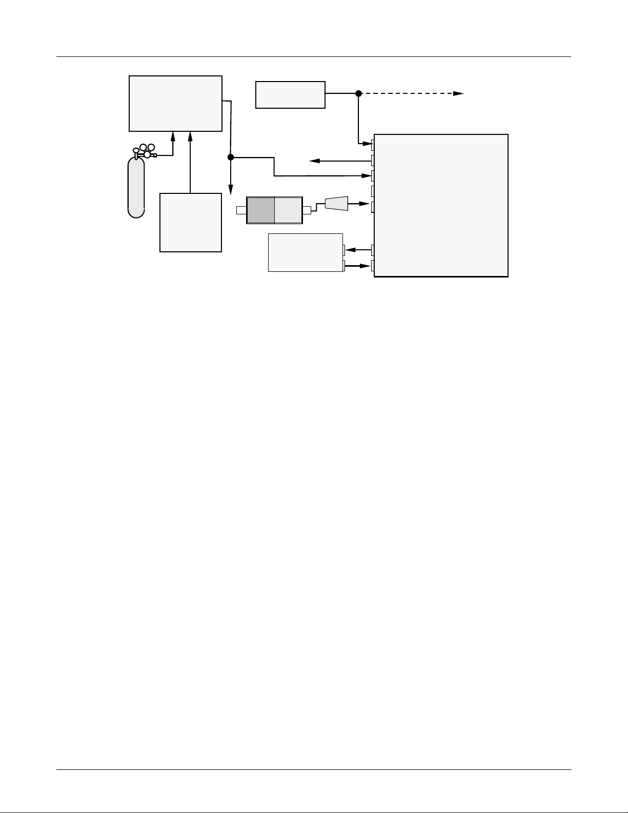
Zero/Span Valves – Option 50
VENT if input is pressurized
le
Sam
Exhaust
S
an
Zero Air
To Converter
From Converter
MODEL
102E
MODEL 700
Gas Dilution Calibrator
(with O3 generator option)
Calibrated
SO
or H2S
2
gas
(At high
concentration)
VENT
MODEL 701
Zero Air
Generator
Source of
SAMPLE Gas
External Zero
Air Scrubber
M501-TRS
Filter
To Analyze
From Analyze
Figure 3-9: Basic Pneumatic Connections for Units with Zero/Span Valve Option
05514 Rev A1 15
GETTING STARTED M102E/M501 TRS
p
r
r
p
(
)
p
r
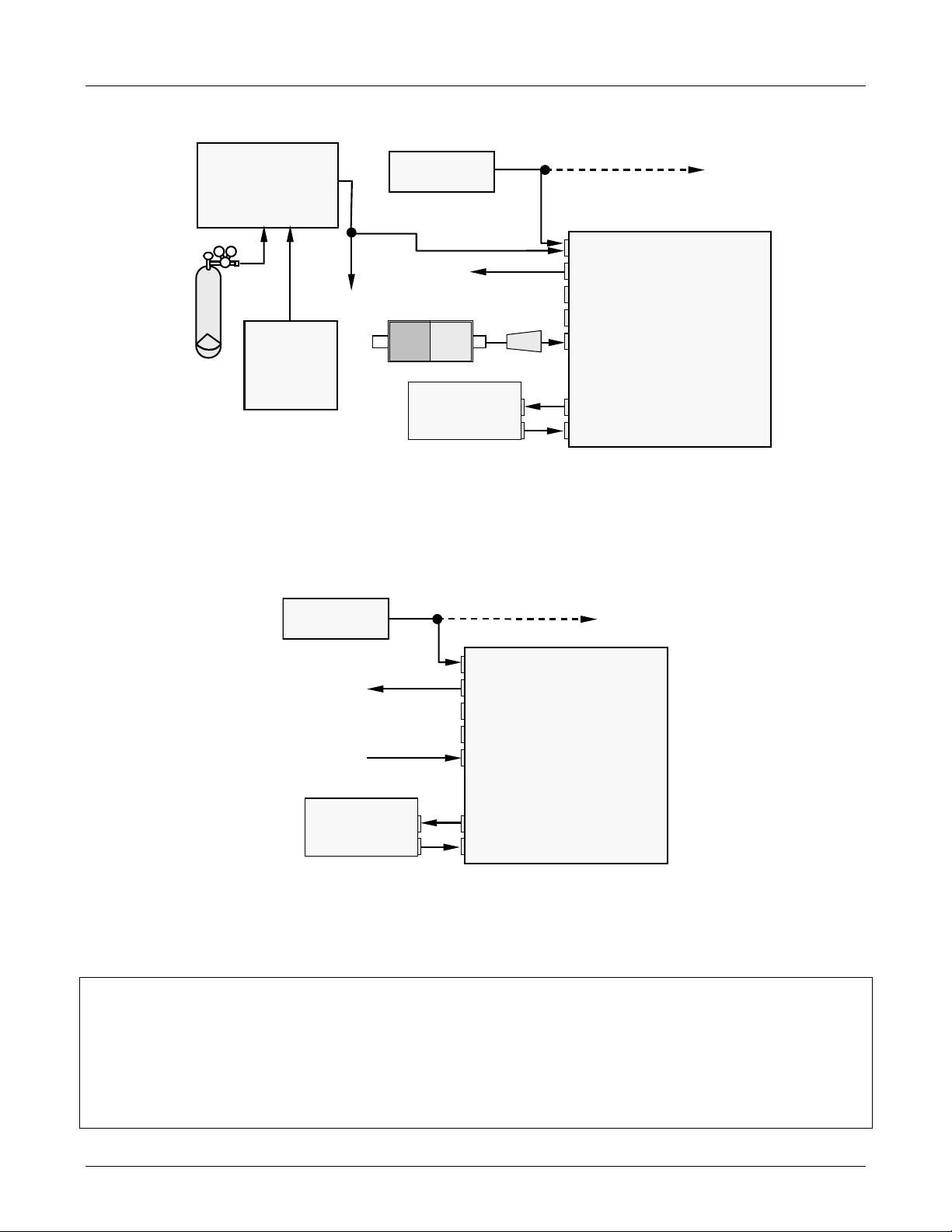
(Addendum to M101E Manual - P/N 04740 Rev A)
MODEL 700
Gas Dilution Calibrator
(with O3 generator option)
Calibrated
H2S gas
(At high
concentration)
VENT
MODEL 701
Zero Air
Generator
Source of
SAMPLE Gas
External Zero
Air Scrubber
M501-TRS
To Analyze
From Analyze
Filter
VENT if input is pressurized
le
Sam
Exhaust
MODEL
102E
Zero Air
To Converter
From Converter
Figure 3-10: Pneumatic Connections for Formal Calibration of Units with an IZS Valve
Option
Source of
SAMPLE Gas
VENT if input is pressurized
Sam
Ambient
Air
M501-TRS
From Analyze
To Analyzer
le
Exhaust
S
an
Zero Air
To Converter
From Converter
MODEL
102E
Scrubber
Figure 3-11: Pneumatic Connections for Informal Calibration Checks of Units with IZS
Valve Option
NOTE
Gas flow must be maintained at all times for units with IZS Options installed. The IZS
option requires a permeation tube ( customer supplied ) which emits H2S. Insufficient
gas flow can build up H2S to levels that will damage the instrument.
Remove the permeation device when taking the analyzer out of operation.
16 05514 Rev A1
M102E/M501 TRS GETTING STARTED
g
(Addendum to M101E Manual - P/N 04740 Rev A)
3.7. Initial Operation
3.7.1. Startup / Warm Up of the M102E
Startup procedures and warm up behavior of the M102E are identical to those described in
Sections 3.2.1 and 3.2.2 of the M101E Manual - P/N 04740 Rev A.
Possible Warning Messages at Start-Up
Warning messages for the M102E is the same as the list of warning messages included in
appendix A—3 of the M101E Manual - P/N 04740 Rev A with the exception that there is no CONV
TEMP WARNING (converter Temperature Warning).
3.7.2. Functional Check of the M102E
To performing an initial functional check of the M102E follow the steps contained in Section 3.2.4
of the M101E Manual - P/N 04740 Rev A.
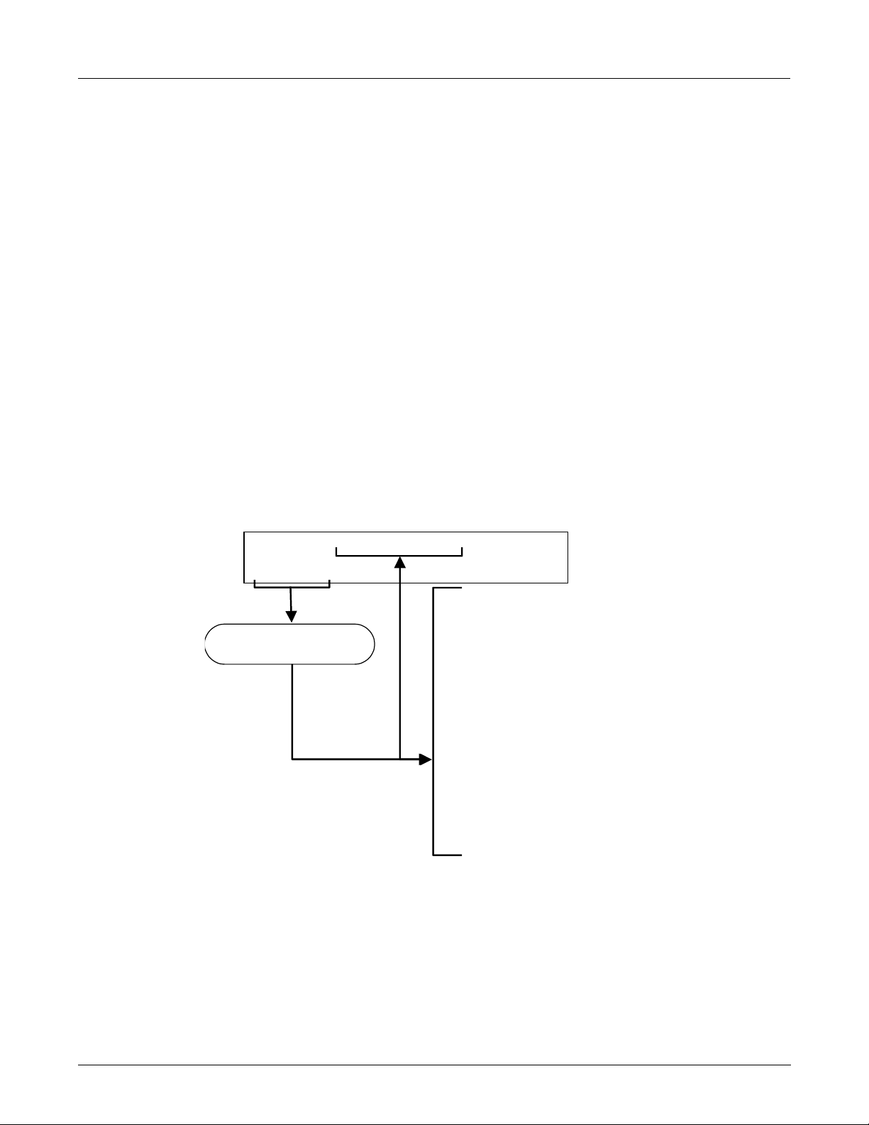
Test Functions
The following diagram supercedes the one found in Step 2 of Section 3.2.4 of the M101E Manual P/N 04740 Rev A.
SAMPLE RANGE = 500.0 PPB TRS = X.X
< TST TST > CAL SETUP
RANGE
TRS STB
PRES
Toggle <TST TST> keys to
scroll throu
1
Only appears if IZS option is
installed.
2
Only appears if analog output A4
is actively reporting a test function.
3
Shown as they appear when analyzer
is in TRS mode. In SO
h list of functions
mode appear as SO2 STB, SO2 OFFS &
2
SAMP FL
PMT
NORM PMT
UV LAMP
LAMP RATIO
STR. LGT
DARK PMT
DARK LAMP
TRS SLOPE
TRS OFFS
HVPS
RCELL TEMP
BOX TEMP
PMT TEMP
IZS TEMP
TEST
TIME
SO2 SLOPE. In multigas mode, both versions appear.
3
Refer to Section
6.2.1 of the M101E
3
Manual - P/N 04740
3
Rev A for definitions
of these test
functions.
1
2
05514 Rev A1 17
GETTING STARTED M102E/M501 TRS
(Addendum to M101E Manual - P/N 04740 Rev A)
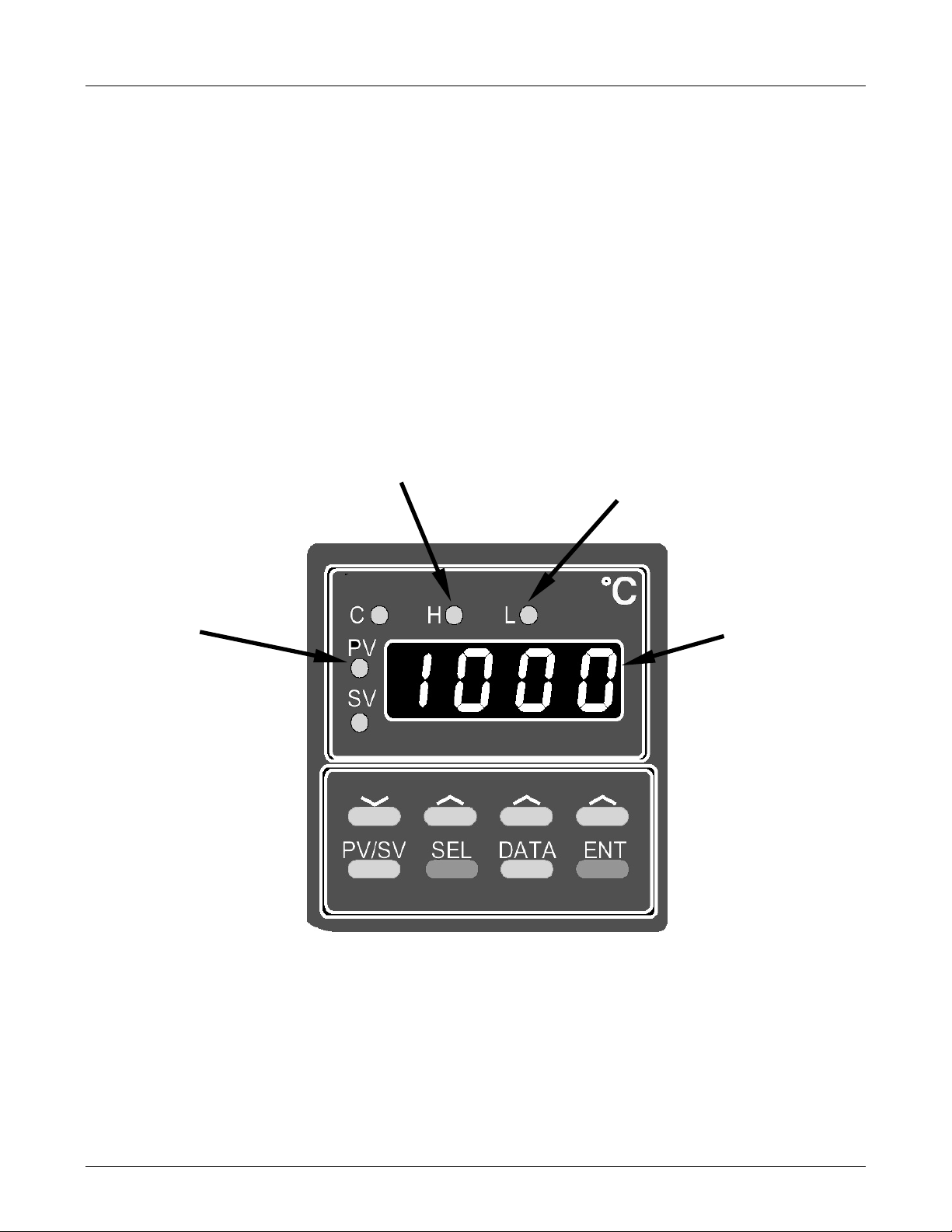
3.7.3. Startup / Warm Up of the M501-TRS
After electrical and pneumatic connections are made, turn on the instrument and pump power.
The exhaust fan should start.
The M501-TRS’ temperature controller is preprogrammed at the factory so no special setup
operation is required. The temperature controller (see Figure 3-12) should immediately come on
in operation mode: the current temperature of the converter oven should the display immediately
appear in the display area and the process
It may take as much as 30 minutes for the oven to reach its nominal operating temperature.
During that initial warm up period the high and low alarms and the M501-TRS single alarm output
are disabled. Both the internal alarms and the alarm output will be automatically enabled once
the converter oven temperature rises above the lower alarm limit.
value (PV) LED should be lit.
Process Variable
LED
High Alarm LED
Low Alarm LED
Display area
Figure 3-12: M501-TRS Temperature Controller Startup
18 05514 Rev A1

M102E/M501 TRS GETTING STARTED
(Addendum to M101E Manual - P/N 04740 Rev A)
3.8. Initial Calibration
Initial calibration of the M102E should be performed with:
• Zero air supplied by a zero air generator such as the Teledyne Instruments’ M701;
• Calibrated H
• With external pneumatic connections as described in Figures 3-7 through 3-11 of this
addendum, and;
• Using the information and procedure included in Section 3.3 of the M101E Manual - P/N
04740 Rev A.
No initial calibration of the M501-TRS temperature controller is required.
Once you have completed the above set-up procedures, please fill out the quality
questionnaire that was shipped with your unit and return it to Teledyne Instruments.
This information is vital to our efforts in continuously improving our service and our
S span gas of the appropriate concentration:
2
NOTE
products. Thank you.
User Notes:
05514 Rev A1 19


M102E/M501 TRS OPTIONAL HARDWARE AND SOFTWARE
(Addendum to M101E Manual - P/N 04740 Rev A)
4. OPTIONAL HARDWARE AND SOFTWARE
This section includes descriptions of the hardware and software options available for the Model
102E analyzer and M501-TRS converter that are different from or not included in Chapter 5 of the
M101E Manual - P/N 04740 Rev A. For all other available options see that document.
For assistance with ordering these options please contact the sales department of Teledyne
Instruments at:
TOLL-FREE: 800-324-5190
TEL: +1 858-657-9800
FAX: +1 858-657-9816
E-MAIL: apisales@teledyne.com
WEB SITE: http://www.teledyne-api.com
4.1. Rack Mount Kits (Options 20a, 20b, 21, 22 & 81)
The following table supercedes the one included in Section 5.1 of the M101E Manual - P/N 04740
Rev A.
OPTION NUMBER DESCRIPTION
OPT 20A Rack mount brackets with 26 in. chassis slides.
OPT 20B Rack mount brackets with 24 in. chassis slides.
OPT 21 Rack mount brackets only
OPT 22 Rack Mount for M501-TRS
OPT 81 Rack Mount for M501-TRS with slides
4.2. Calibration Valves Options
4.2.1. Zero/Span Valves (Option 50) & Internal Zero/Span Gas
Generator (Option 51)
The description of the construction and operation for the zero span and IZS valve options for the
M102E TRS is identical to that information contained in Section 5.4of the M101E Manual - P/N
04740 Rev A.
The internal pneumatic flow or the M102E with either of these options installed is however
different. See:
• Figure 4-1 for an illustration of the M102E internal gas flow with the zero/span valves
(option 50), and;
• Figure 4-2 for an illustration of the M102E internal gas flow with the IZS valve (option 1).
05514 Rev A1 21
Loading...