


Operation Manual
Model T700
Dynamic Dilution Calibrator
Also supports operation of
Model T700U
(when used in conjunction with T700U addendum, PN 06876)
© TELEDYNE ADVANCED POLLUTION INSTRUMENTATION (TAPI)
9480 CARROLL PARK DRIVE
SAN DIEGO, CA 92121-5201
USA
Toll-free Phone: 800-324-5190
Phone: 858-657-9800
Fax: 858-657-9816
Email: api-sales@teledyne.com
Website: http://www.teledyne-api.com/
Copyright 2010-2012 |
06873B DCN6388 |
Teledyne Advanced Pollution Instrumentation |
08 May 2012 |
ABOUT TELEDYNE ADVANCED POLLUTION INSTRUMENTATION (TAPI)
Teledyne Advanced Pollution Instrumentation (TAPI), a business unit of Teledyne Instruments, Inc., is a worldwide market leader in the design and manufacture of precision analytical instrumentation used for air quality monitoring, continuous emissions monitoring, and specialty process monitoring applications. Founded in San Diego, California, in 1988, TAPI introduced a complete line of Air Quality Monitoring (AQM) instrumentation, which comply with the United States Environmental Protection Administration (EPA) and international requirements for the measurement of criteria pollutants, including CO, SO2, NOX and Ozone.
Since 1988 TAPI has combined state-of-the-art technology, proven measuring principles, stringent quality assurance systems and world class after-sales support to deliver the best products and customer satisfaction in the business.
For further information on our company, our complete range of products, and the applications that they serve, please visit www.teledyne-api.com or contact sales@teledyne-api.com.
NOTICE OF COPYRIGHT
© 2010-2012 Teledyne Advanced Pollution Instrumentation. All rights reserved.
TRADEMARKS
All trademarks, registered trademarks, brand names or product names appearing in this document are the property of their respective owners and are used herein for identification purposes only.
06873B DCN6388 |
i |

Teledyne API – Model T700 Dynamic Dilution Calibrator
This page intentionally left blank.
ii |
06873B DCN6388 |
IMPORTANT SAFETY INFORMATION
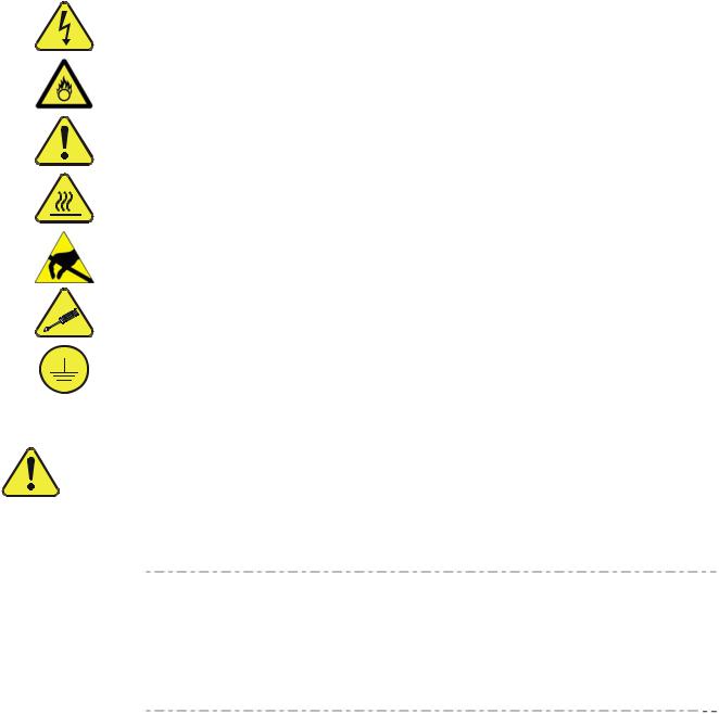
Important safety messages are provided throughout this manual for the purpose of avoiding personal injury or instrument damage. Please read these messages carefully. Each safety message is associated with a safety alert symbol, and are placed throughout this manual and inside the instrument. The symbols with messages are defined as follows:
WARNING: Electrical Shock Hazard
HAZARD: Strong oxidizer
GENERAL WARNING/CAUTION: Read the accompanying message for specific information.
CAUTION: Hot Surface Warning
Do Not Touch: Touching some parts of the instrument without protection or proper tools could result in damage to the part(s) and/or the instrument.
Technician Symbol: All operations marked with this symbol are to be performed by qualified maintenance personnel only.
Electrical Ground: This symbol inside the instrument marks the central safety grounding point for the instrument.
|
CAUTION |
|
|
|
This instrument should only be used for the purpose and in the |
|
|
|
manner described in this manual. If you use this instrument in a |
|
|
|
manner other than that for which it was intended, unpredictable |
|
|
|
behavior could ensue with possible hazardous consequences. |
|
|
|
NEVER use any gas analyzer to sample combustible gas(es)! |
|
|
Note |
For Technical Assistance regarding the use and maintenance of this |
||
instrument or any other Teledyne API product, please contact Teledyne |
|||
|
|||
|
API’s Customer Service Department: |
||
Telephone: 800-324-5190 Email: api-customerservice@teledyne.com
or by accessing various service options on our website: http://www.teledyne-api.com/.
06873B DCN6388 |
iii |

Teledyne API – Model T700 Dynamic Dilution Calibrator
CONSIGNES DE SÉCURITÉ
Des consignes de sécurité importantes sont fournies tout au long du présent manuel dans le but d’éviter des blessures corporelles ou d’endommager les instruments. Veuillez lire attentivement ces consignes. Chaque consigne de sécurité est représentée par un pictogramme d’alerte de sécurité; ces pictogrammes se retrouvent dans ce manuel et à l’intérieur des instruments. Les symboles correspondent aux consignes suivantes :
AVERTISSEMENT : Risque de choc électrique
DANGER : Oxydant puissant
AVERTISSEMENT GÉNÉRAL / MISE EN GARDE : Lire la consigne complémentaire pour des renseignements spécifiques
MISE EN GARDE : Surface chaude
Ne pas toucher : Toucher à certaines parties de l’instrument sans protection ou sans les outils appropriés pourrait entraîner des dommages aux pièces ou à l’instrument.
Pictogramme « technicien » : Toutes les opérations portant ce symbole doivent être effectuées uniquement par du personnel de maintenance qualifié.
Mise à la terre : Ce symbole à l’intérieur de l’instrument détermine le point central de la mise à la terre sécuritaire de l’instrument.
MISE EN GARDE
Cet instrument doit être utilisé aux fins décrites et de la manière décrite dans ce manuel. Si vous utilisez cet instrument d’une autre manière que celle pour laquelle il a été prévu, l’instrument pourrait se comporter de façon imprévisible et entraîner des conséquences dangereuses.
NE JAMAIS utiliser un analyseur de gaz pour échantillonner des gaz combustibles!
iv |
06873B DCN6388 |

WARRANTY
WARRANTY POLICY (02024F)
Teledyne Advanced Pollution Instrumentation (TAPI), a business unit of Teledyne Instruments, Inc., provides that:
Prior to shipment, TAPI equipment is thoroughly inspected and tested. Should equipment failure occur, TAPI assures its customers that prompt service and support will be available.
COVERAGE
After the warranty period and throughout the equipment lifetime, TAPI stands ready to provide on-site or in-plant service at reasonable rates similar to those of other manufacturers in the industry. All maintenance and the first level of field troubleshooting are to be performed by the customer.
NON-TAPI MANUFACTURED EQUIPMENT
Equipment provided but not manufactured by TAPI is warranted and will be repaired to the extent and according to the current terms and conditions of the respective equipment manufacturer’s warranty.
PRODUCT RETURN
All units or components returned to Teledyne API should be properly packed for handling and returned freight prepaid to the nearest designated Service Center. After the repair, the equipment will be returned, freight prepaid.
The complete Terms and Conditions of Sale can be reviewed at http://www.teledyneapi.com/terms_and_conditions.asp
CAUTION – Avoid Warranty Invalidation
Failure to comply with proper anti-Electro-Static Discharge (ESD) handling and packing instructions and Return Merchandise Authorization (RMA) procedures when returning parts for repair or calibration may void your warranty. For anti-ESD handling and packing instructions please refer to “Packing Components for Return to Teledyne API’s Customer Service” in the Primer on Electro-Static Discharge section of this manual, and for RMA procedures please refer to our Website at http://www.teledyneapi.com under Customer Support > Return Authorization.
06873B DCN6388 |
v |

Teledyne API – Model T700 Dynamic Dilution Calibrator
This page intentionally left blank.
vi |
06873B DCN6388 |

ABOUT THIS MANUAL
|
|
|
Presented here is information regarding the documents that are included with this |
|
|
|
|
manual (Structure) and how the content is organized (Organization). |
|
|
|
|
STRUCTURE |
|
|
|
|
This T700 manual, PN 06873, is comprised of multiple documents, assembled in PDF |
|
|
|
|
format, as listed below. |
|
|
|
|
|
|
|
Part No. |
Rev |
Name/Description |
|
|
06873 |
B |
Operation Manual, T700 Dynamic Dilution Calibrator |
|
|
|
|
|
|
|
05623 |
D |
Appendix A, Menu Trees and related software documentation |
|
|
06852 |
B |
Spare Parts List (in Appendix B of this manual) |
|
|
07565 |
A |
Recommended Spares Stocking Levels (in Appendix B of this manual) |
|
|
|
|
|
|
|
05625 |
B |
Appendix C, Repair Form |
|
|
069140100 |
A |
Interconnect List (in Appendix D of this manual) |
|
|
|
|
Appendix D, Schematics: |
|
|
06914 |
A |
Interconnect Diagram |
|
|
04420 |
B |
SCH, PCA 04120, UV DETECTOR |
|
|
04422 |
A |
SCH, PCA 04144, DC HEATER/TEMP SENSOR |
|
|
04421 |
A |
SCH, PCA 04166, UV LAMP POWER SUPPLY |
|
|
04354 |
D |
SCH, PCA 04003, Pressure/Flow Transducer Interface |
|
|
04524 |
E |
SCH, PCA 04523, RELAY CARD |
|
|
05698 |
B |
SCH, PCA 05697 ADPTR, EXT VALVE DRIVER |
|
|
05803 |
B |
SCH, PCA 05802, MOTHERBOARD, GEN-5 |
|
|
06698 |
D |
SCH, PCA 06670, INTRFC, LCD TCH SCRN, |
|
|
06882 |
B |
SCH, LVDS TRANSMITTER BOARD |
|
|
06731 |
B |
SCH, AUX-I/O BOARD |
|
|
Note |
|
We recommend that this manual be read in its entirety before any attempt is |
|
|
|
|
made to operate the instrument. |
|
|
|
|
ORGANIZATION |
|
|
|
|
This manual is divided among three main parts and a collection of appendices at the end. |
|
|
|
|
Part I contains introductory information that includes an overview of the calibrator, |
|
|
|
|
descriptions of the available options, specifications, installation and connection |
|
|
|
|
instructions, and the initial calibration and functional checks.. |
|
|
|
|
Part II comprises the operating instructions, which include basic, advanced and remote |
|
|
|
|
operation, calibration, diagnostics, testing, validating and verifying. |
|
|
|
|
Part III provides detailed technical information, such as principles of operation, |
|
|
|
|
maintenance, and troubleshooting and repair. It includes Frequently Asked Questions |
|
|
|
|
|
|
06873B DCN6388 |
|
|
vii |
|

Teledyne API – Model T700 Dynamic Dilution Calibrator
and a Glossary, and also has a section that provides important information about electrostatic discharge and avoiding its consequences.
The appendices at the end of this manual provide support information such as, versionspecific software documentation, lists of spare parts and schematics.
viii |
06873B DCN6388 |
REVISION HISTORY
This section provides information regarding the initial release and subsequent changes to this manual.
T700 Manual, PN 06873 Rev B, DCN 6388
|
Date |
Rev |
DCN |
Change Summary |
2012 |
May 08 |
B |
6388 |
Administrative changes: restructure/reformat |
|
|
|
|
Technical changes: various |
2010 |
October 06 |
A |
5839 |
Initial Release |
Document part numbers and revision letters included in the initial release are as follows:
PN |
Rev |
Document |
|
|
|
06873 |
B |
Operation Manual, T700 Dynamic Dilution Calibrator |
05623 |
D |
Appendix A, Menu Trees w/ related software documentation |
06852 |
B |
Spare Parts List (in Appendix B of this manual) |
05625 |
B |
Appendix C, Repair Form |
069140100 |
A |
Interconnect List (in Appendix D of this manual) |
06914 |
A |
Interconnect Diagram |
04420 |
B |
SCH, PCA 04120, UV DETECTOR |
04422 |
A |
SCH, PCA 04144, DC HEATER/TEMP SENSOR |
04421 |
A |
SCH, PCA 04166, UV LAMP POWER SUPPLY |
04354 |
D |
SCH, PCA 04003, Pressure/Flow Transducer Interface |
04524 |
E |
SCH, PCA 04523, RELAY CARD |
05698 |
B |
SCH, PCA 05697 ADPTR, EXT VALVE DRIVER |
05803 |
B |
SCH, PCA 05802, MOTHERBOARD, GEN-5 |
06698 |
D |
SCH, PCA 06670, INTRFC, LCD TCH SCRN, |
06882 |
B |
SCH, LVDS TRANSMITTER BOARD |
|
|
|
06731 |
B |
SCH, AUX-I/O BOARD |
06873B DCN6388 |
ix |

Teledyne API – Model T700 Dynamic Dilution Calibrator
This page intentionally left blank.
x |
06873B DCN6388 |

TABLE OF CONTENTS |
|
PART I – GENERAL INFORMATION .................................................................................... |
21 |
1. INTRODUCTION ................................................................................................................. |
23 |
1.1. T700 Calibrator Overview ............................................................................................................................ |
23 |
1.2. Features ....................................................................................................................................................... |
23 |
1.3. Options......................................................................................................................................................... |
24 |
2. SPECIFICATIONS AND APPROVALS............................................................................... |
27 |
2.1. Specifications............................................................................................................................................... |
27 |
2.2. Approvals and Certifications ........................................................................................................................ |
28 |
2.2.1. Safety..................................................................................................................................................... |
28 |
2.2.2. EMC ....................................................................................................................................................... |
29 |
2.2.3. Other Type Certifications ....................................................................................................................... |
29 |
3. GETTING STARTED........................................................................................................... |
31 |
3.1. Unpacking and Initial Setup ......................................................................................................................... |
31 |
3.1.1. VENTILATION CLEARANCE ................................................................................................................ |
32 |
3.2. Calibrator Layout.......................................................................................................................................... |
32 |
3.2.1. Front Panel ............................................................................................................................................ |
33 |
3.2.2. Rear Panel ............................................................................................................................................. |
36 |
3.2.3. Internal Layout ....................................................................................................................................... |
38 |
3.3. Connections and Setup................................................................................................................................ |
40 |
3.3.1. Electrical Connections ........................................................................................................................... |
40 |
3.3.1.1. Connecting Power .......................................................................................................................... |
40 |
3.3.1.2. Connecting Analog Outputs ........................................................................................................... |
41 |
3.3.1.3. Connecting the Status Outputs ...................................................................................................... |
41 |
3.3.1.4. Connecting the Control Inputs........................................................................................................ |
43 |
3.3.1.5. Connecting the Control Outputs ..................................................................................................... |
45 |
3.3.1.6. Connecting the External Valve Driver Option................................................................................. |
46 |
3.3.1.7. Connecting the Communications Interfaces .................................................................................. |
47 |
3.3.2. Pneumatic Connections......................................................................................................................... |
54 |
3.3.2.1. About Diluent Gas (Zero Air) .......................................................................................................... |
54 |
3.3.2.2. About Calibration Gas .................................................................................................................... |
54 |
3.3.2.3. Connecting Diluent Gas to the Calibrator....................................................................................... |
58 |
3.3.2.4. Connecting Calibration Source Gas to the T700 Calibrator........................................................... |
58 |
3.3.2.5. Connecting Gas Outputs from the Calibrator ................................................................................. |
59 |
3.3.2.6. Other Pneumatic Connections ....................................................................................................... |
63 |
3.3.3. Permeation Tube Setup for the T700 .................................................................................................... |
74 |
3.3.4. Permeation Tube Calculation ................................................................................................................ |
75 |
3.4. Startup, Functional Checks, and Initial calibration....................................................................................... |
77 |
3.4.1. Start Up.................................................................................................................................................. |
77 |
3.4.2. Warning Messages ................................................................................................................................ |
77 |
3.4.3. Functional Checks ................................................................................................................................. |
80 |
3.4.4. Setting Up the Calibration Gas Inlet Ports............................................................................................. |
81 |
3.4.5. Default Gas Types ................................................................................................................................. |
81 |
3.4.6. User Defined Gas Types ....................................................................................................................... |
81 |
3.4.6.1. User Defined Gas Types – General ............................................................................................... |
81 |
3.4.6.2. User Defined Gas Types – Defining the Gas Name ...................................................................... |
83 |
3.4.6.3. User Defined Gas Types – Setting the MOLAR MASS.................................................................. |
84 |
3.4.6.4. Enabling and Disabling Gas Types ................................................................................................ |
86 |
3.4.7. Defining Calibration Source Gas Cylinders ........................................................................................... |
87 |
3.4.7.1. Setting Up the Ports with Single Gas Cylinders ............................................................................. |
87 |
3.4.7.2. Setting Up the Ports with Multiple Gas Cylinders........................................................................... |
89 |
06873B DCN6388 |
xi |

Teledyne API – Model T700 Dynamic Dilution Calibrator |
|
3.4.8. Selecting an Operating Mode for the O3 Generator.............................................................................. |
90 |
3.4.8.1. CNST (CONSTANT)....................................................................................................................... |
90 |
3.4.8.2. REF (REFERENCE)....................................................................................................................... |
90 |
3.4.8.3. BNCH (BENCH) ............................................................................................................................. |
90 |
3.4.9. Setting the T700’s Total Gas Flow Rate................................................................................................ |
91 |
PART II – OPERATING INSTRUCTIONS.............................................................................. |
93 |
4. OVERVIEW OF OPERATING MODES AND BASIC OPERATION .................................... |
95 |
4.1. STANDBY MODE ........................................................................................................................................ |
98 |
4.1.1. Test Functions ....................................................................................................................................... |
99 |
4.2. GENERATE MODE................................................................................................................................... |
102 |
4.2.1. GENERATE AUTO: Basic Generation of Calibration Mixtures...................................................... |
104 |
4.2.2. GENERATE MAN: Generating Calibration Mixtures Manually ...................................................... |
106 |
4.2.2.1. Determining the Source Gas Flow Rate...................................................................................... |
106 |
4.2.2.2. Determining the Diluent Gas Flow Rate...................................................................................... |
107 |
4.2.2.3. Determining the Diluent Gas Flow Rate with the Optional O3 Generator Installed ..................... |
107 |
4.2.2.4. Setting the Source Gas and Diluent Flow Rates Using the GENERATE MAN Menu............ |
108 |
4.2.3. GENERATE GPT: Performing a Gas Phase Titration Calibration ................................................. |
109 |
4.2.3.1. GPT Theory ................................................................................................................................. |
109 |
4.2.3.2. Choosing an Input Concentration for the NO .............................................................................. |
109 |
4.2.3.3. Determining the TOTAL FLOW for GPT Calibration Mixtures .................................................... |
110 |
4.2.3.4. T700 Calibrator GPT Operation .................................................................................................. |
111 |
4.2.3.5. Initiating a GPT Calibration Gas Generation............................................................................... |
112 |
4.2.4. GENERATE GPTPS: Performing a Gas Phase Titration Pre-Set ................................................. |
113 |
4.2.4.1. T700 Calibrator GPTPS Operation.............................................................................................. |
113 |
4.2.4.2. Initiating a GPT Pre-Set............................................................................................................... |
115 |
4.2.5. GENERATE PURGE: Activating the T700’s Purge Feature.......................................................... |
116 |
4.2.6. GENERATE ACT>: VIEWING CONCENTRATIONS Generated from Multi-Gas Cylinders........... |
118 |
4.2.6.1. Using the T700 Calibrator as an O3 Photometer......................................................................... |
118 |
4.3. AUTOMATIC CALIBRATION SEQUENCES ............................................................................................ |
119 |
4.3.1. SETUP SEQ: Programming Calibration Sequences...................................................................... |
119 |
4.3.1.1. Activating a Sequence from the T700 Front Panel ..................................................................... |
121 |
4.3.1.2. Naming a Sequence.................................................................................................................... |
122 |
4.3.1.3. Setting the Repeat Count for a Sequence .................................................................................. |
123 |
4.3.1.4. Using the T700’s Internal Clock to Trigger Sequences............................................................... |
124 |
4.3.1.5. Setting Up Control Inputs for a Sequence................................................................................... |
127 |
4.3.1.6. Setting Up Control Outputs for a Sequence................................................................................ |
128 |
4.3.1.7. Setting the PROGRESS Reporting Mode for the Sequences..................................................... |
130 |
4.3.2. Adding Sequence Steps ..................................................................................................................... |
131 |
4.3.2.1. The GENERATE Step ................................................................................................................. |
132 |
4.3.2.2. The GPT Step.............................................................................................................................. |
133 |
4.3.2.3. The GPTPS Step......................................................................................................................... |
134 |
4.3.2.4. The PURGE Step ........................................................................................................................ |
135 |
4.3.2.5. The STANDBY Step.................................................................................................................... |
135 |
4.3.2.6. The DURATION Step .................................................................................................................. |
136 |
4.3.2.7. The EXECSEQ Step.................................................................................................................... |
136 |
4.3.2.8. The CC OUTPUT Step................................................................................................................ |
138 |
4.3.2.9. The MANUAL Gas Generation Step ........................................................................................... |
139 |
4.3.2.10. Deleting or Editing an Individual Step in a Sequence ............................................................... |
140 |
4.3.3. Deleting a Sequence .......................................................................................................................... |
141 |
4.4. SETUP CFG ......................................................................................................................................... |
142 |
4.5. SETUP CLK: Setting the Internal Time-of-Day Clock and Adjusting Speed........................................ |
143 |
4.5.1. Setting the Internal Clock’s Time and Day ......................................................................................... |
143 |
4.5.2. Adjusting the Internal Clock’s Speed.................................................................................................. |
144 |
4.6. SETUP PASS ....................................................................................................................................... |
145 |
4.7. SETUP COMM: Communications Ports............................................................................................... |
147 |
4.7.1. ID (Machine Identification) .................................................................................................................. |
147 |
xii |
06873B DCN6388 |

Teledyne API – Model T700 Dynamic Dilution Calibrator |
|
4.7.2. INET (Ethernet)................................................................................................................................... |
148 |
4.7.3. COM1 and COM2 (Mode, Baud Rate and Test Port)......................................................................... |
148 |
4.8. SETUP MORE FLOW...................................................................................................................... |
148 |
4.9. SETUP MORE VARS: Internal Variables (VARS)........................................................................... |
148 |
4.10. SETUP MORE DIAG: dIAGNOSTICS fUNCTIONS...................................................................... |
151 |
4.10.1. TEST CHAN OUTPUT: Using the TEST Channel Analog Output............................................... |
151 |
4.10.1.1. Configuring the Test Channel Analog Output ........................................................................... |
151 |
4.10.1.2. Selecting a Test Channel Function to Output ........................................................................... |
154 |
4.10.1.3. Test Channel Voltage Range Configuration.............................................................................. |
156 |
4.10.1.4. Turning the Test Channel Over-Range Feature ON/OFF......................................................... |
157 |
4.10.1.5. Adding a Recorder Offset to the Test Channel ......................................................................... |
158 |
4.10.1.6. Test Channel Calibration........................................................................................................... |
160 |
4.10.1.7. AIN Calibration .......................................................................................................................... |
165 |
4.11. SETUP LVL: Setting up and using LEADS (Dasibi) Operating Levels .............................................. |
166 |
4.11.1. General Information about LEADS LEVELS .................................................................................... |
166 |
4.11.2. Dot commands.................................................................................................................................. |
166 |
4.11.3. Levels................................................................................................................................................ |
167 |
4.11.4. Activating an existing LEVEL............................................................................................................ |
167 |
4.11.5. Programming New LEVELS ............................................................................................................. |
168 |
4.11.5.1. Creating a GENERATE LEVEL................................................................................................. |
169 |
4.11.5.2. Creating a GPT LEVEL ............................................................................................................. |
170 |
4.11.5.3. Creating a GPTPS LEVEL ........................................................................................................ |
171 |
4.11.5.4. Creating a MANUAL LEVEL...................................................................................................... |
172 |
4.11.5.5. Editing or Deleting a LEVEL...................................................................................................... |
173 |
4.11.6. CONFIGURING LEVEL Status Blocks ............................................................................................. |
174 |
5. COMMUNICATIONS SETUP AND REMOTE OPERATION ............................................. |
175 |
5.1. Data Terminal/Communication Equipment (DTE DCE)............................................................................ |
175 |
5.2. Communication Modes, Baud Rate and Port Testing ................................................................................... |
176 |
5.2.1. Communication Modes ....................................................................................................................... |
176 |
5.2.2. COM Port Baud Rate.......................................................................................................................... |
179 |
5.2.3. COM Port Testing ............................................................................................................................... |
180 |
5.3. RS-485 (Option)........................................................................................................................................ |
181 |
5.4. Remote Access via the Ethernet............................................................................................................... |
181 |
5.4.1. Configuring the Ethernet Interface using DHCP................................................................................. |
181 |
5.4.1.1. Manually Configuring the Network IP Addresses........................................................................ |
184 |
5.4.2. Changing the Calibrator’s HOSTNAME.............................................................................................. |
186 |
5.4.3. USB PORT (Option) for Remote Access............................................................................................ |
187 |
6. REMOTE OPERATION ..................................................................................................... |
189 |
6.1. Computer Mode ........................................................................................................................................ |
189 |
6.1.1. Remote Control via APICOM.............................................................................................................. |
189 |
6.2. Interactive Mode........................................................................................................................................ |
190 |
6.2.1. Remote Control via a Terminal Emulation Program ........................................................................... |
190 |
6.2.1.1. Help Commands in Interactive Mode .......................................................................................... |
190 |
6.2.1.2. Command Syntax ........................................................................................................................ |
191 |
6.2.1.3. Data Types .................................................................................................................................. |
192 |
6.2.1.4. Status Reporting.......................................................................................................................... |
192 |
6.2.1.5. General Message Format............................................................................................................ |
193 |
6.3. Remote Access by Modem ....................................................................................................................... |
193 |
6.4. Password Security for Serial Remote communications............................................................................ |
196 |
7. CALIBRATION AND VERIFICATION ............................................................................... |
197 |
7.1. Viewing the Performance Statistics for the T700’s MFC’s....................................................................... |
197 |
7.2. Calibrating the Output of the T700’s MFC’s.............................................................................................. |
199 |
7.2.1. Setup for Verification and Calibration of the T700’s MFC’s................................................................ |
200 |
7.2.2. Verifying and Calibrating the T700’s MFC’s ....................................................................................... |
201 |
7.3. Verifying and Calibrating the T700’s Optional O3 Photometer.................................................................. |
202 |
7.3.1. Setup for Verifying O3 Photometer Performance ............................................................................... |
202 |
06873B DCN6388 |
xiii |

Teledyne API – Model T700 Dynamic Dilution Calibrator |
|
7.3.2. Verifying O3 Photometer Performance............................................................................................... |
203 |
7.3.3. Setup for Calibration of the O3 Photometer ....................................................................................... |
204 |
7.3.3.1. Setup Using Direct Connections ................................................................................................. |
204 |
7.3.3.2. Setup Using a Calibration Manifold ............................................................................................. |
205 |
7.3.3.3. Calibration Manifold Exhaust/Vent Line ...................................................................................... |
205 |
7.3.4. Performing an O3 Photometer External Calibration............................................................................ |
205 |
7.3.4.1. Photometer Zero Calibration ....................................................................................................... |
206 |
7.3.4.2. Photometer Span Calibration ...................................................................................................... |
207 |
7.3.5. O3 Photometer Dark Calibration......................................................................................................... |
208 |
7.3.6. O3 Photometer Gas Flow Calibration................................................................................................. |
209 |
7.3.7. O3 Photometer BackPressure Compensation Calibration ................................................................. |
210 |
7.4. Calibrating the O3 Generator .................................................................................................................... |
211 |
7.4.1. Setup for Verification and Calibration the O3 Generator..................................................................... |
211 |
7.4.1.1. Setup Using Direct Connections ................................................................................................. |
211 |
7.4.2. O3 Generator Calibration Procedure.................................................................................................. |
213 |
7.4.2.1. Viewing O3 Generator Calibration Points .................................................................................... |
213 |
7.4.2.2. Adding or Editing O3 Generator Calibration Points ..................................................................... |
214 |
7.4.2.3. Deleting O3 Generator Calibration Points.................................................................................... |
215 |
7.4.2.4. Turning O3 Generator Calibration Points ON / OFF.................................................................... |
216 |
7.4.2.5. Performing an Automatic Calibration of the Optional O3 Generator............................................ |
217 |
7.5. T700 Gas Pressure Sensor Calibration .................................................................................................... |
218 |
7.5.1.1. Calibrating the Diluent, Cal Gas Optional O3 Generator Pressure Sensors ............................... |
220 |
7.5.1.2. Calibrating the Optional O3 Photometer Sample Gas Pressure Sensors ................................... |
221 |
PART III – MAINTENANCE AND SERVICE ........................................................................ |
223 |
8. MAINTENANCE ................................................................................................................ |
225 |
8.1. Maintenance Schedule ............................................................................................................................. |
225 |
8.2. Maintenance Procedures .......................................................................................................................... |
227 |
8.2.1. Auto Leak Check................................................................................................................................. |
227 |
8.2.1.1. Equipment Required.................................................................................................................... |
227 |
8.2.1.2. Setup Auto Leak Check............................................................................................................... |
227 |
8.2.1.3. Performing the Auto Leak Check Procedure............................................................................... |
230 |
8.2.1.4. Returning the T700 to Service after Performing an Auto Leak Check ........................................ |
230 |
8.2.2. Cleaning or Replacing the Absorption Tube....................................................................................... |
231 |
8.2.3. UV Source Lamp Adjustment ............................................................................................................. |
232 |
8.2.4. UV Source Lamp Replacement .......................................................................................................... |
233 |
8.2.5. Ozone Generator UV Lamp Adjustment or Replacement .................................................................. |
234 |
9. TROUBLESHOOTING AND SERVICE............................................................................. |
239 |
9.1. General Troubleshooting .......................................................................................................................... |
239 |
9.1.1. Fault Diagnosis with WARNING Messages........................................................................................ |
240 |
9.1.2. Fault Diagnosis With Test Functions .................................................................................................. |
244 |
9.1.3. Using the Diagnostic Signal I/O Function ........................................................................................... |
246 |
9.2. Using the Analog Output Test Channel .................................................................................................... |
248 |
9.3. Using the Internal Electronic Status LEDs................................................................................................ |
249 |
9.3.1. CPU Status Indicator .......................................................................................................................... |
249 |
9.3.2. Relay PCA Status LEDs ..................................................................................................................... |
249 |
9.3.2.1. I2C Bus Watchdog Status LEDs .................................................................................................. |
249 |
9.3.2.2. O3 Option Status LEDs................................................................................................................ |
250 |
9.3.3. Valve Driver PCA STATUS LEDs....................................................................................................... |
251 |
9.4. Subsystem Checkout ................................................................................................................................ |
252 |
9.4.1. Verify Subsystem Calibration.............................................................................................................. |
252 |
9.4.2. AC Main Power ................................................................................................................................... |
252 |
9.4.3. DC Power Supply................................................................................................................................ |
253 |
9.4.4. I2C Bus ................................................................................................................................................ |
254 |
9.4.5. Touchscreen Interface ........................................................................................................................ |
254 |
9.4.6. LCD Display Module ........................................................................................................................... |
255 |
9.4.7. Relay PCA .......................................................................................................................................... |
255 |
xiv |
06873B DCN6388 |

Teledyne API – Model T700 Dynamic Dilution Calibrator |
|
9.4.8. Valve Driver PCA ................................................................................................................................ |
255 |
9.4.9. Input Gas Pressure / Flow Sensor Assembly ..................................................................................... |
256 |
9.4.10. PHOTOMETER O3 Generator Pressure/FLOW SENSOR Assembly ............................................. |
257 |
9.4.11. Motherboard...................................................................................................................................... |
258 |
9.4.11.1. A/D Functions ............................................................................................................................ |
258 |
9.4.11.2. Test Channel / Analog Outputs Voltage.................................................................................... |
258 |
9.4.11.3. Status Outputs........................................................................................................................... |
260 |
9.4.11.4. Control Inputs ............................................................................................................................ |
261 |
9.4.11.5. Control Outputs ......................................................................................................................... |
261 |
9.4.12. CPU .................................................................................................................................................. |
262 |
9.4.13. The Calibrator Doesn’t Appear on the Lan or Internet...................................................................... |
262 |
9.4.14. RS-232 Communications.................................................................................................................. |
263 |
9.4.14.1. General RS-232 Troubleshooting.............................................................................................. |
263 |
9.4.14.2. Troubleshooting Calibrator/Modem or Terminal Operation....................................................... |
263 |
9.4.15. Temperature Problems ..................................................................................................................... |
264 |
9.4.15.1. Box / Chassis Temperature....................................................................................................... |
264 |
9.4.15.2. Photometer Sample Chamber Temperature ............................................................................. |
264 |
9.4.15.3. UV Lamp Temperature.............................................................................................................. |
264 |
9.4.15.4. Ozone Generator Temperature ................................................................................................. |
265 |
9.5. TroubleShooting the Optional O3 Photometer .......................................................................................... |
265 |
9.5.1. Dynamic Problems with the Optional O3 Photometer ........................................................................ |
265 |
9.5.1.1. Noisy or Unstable O3 Readings at Zero ...................................................................................... |
265 |
9.5.1.2. Noisy, Unstable, or Non-Linear Span O3 Readings .................................................................... |
266 |
9.5.1.3. Slow Response to Changes in Concentration............................................................................. |
266 |
9.5.1.4. The Analog Output Signal Level Does Not Agree With Front Panel Readings........................... |
266 |
9.5.1.5. Cannot Zero................................................................................................................................. |
266 |
9.5.1.6. Cannot Span................................................................................................................................ |
266 |
9.5.2. Checking Measure / Reference Valve ................................................................................................ |
267 |
9.5.3. Checking The UV Lamp Power Supply .............................................................................................. |
268 |
9.6. TroubleShooting the Optional O3 generator.............................................................................................. |
269 |
9.6.1. Checking The UV Source Lamp Power Supply.................................................................................. |
269 |
9.7. Service Procedures................................................................................................................................... |
270 |
9.7.1. Disk-On-Module Replacement Procedure.......................................................................................... |
270 |
9.8. Technical Assistance ................................................................................................................................ |
270 |
9.9. Frequently Asked Questions (FAQs) ........................................................................................................ |
271 |
10. PRINCIPLES OF OPERATION ....................................................................................... |
273 |
10.1. Basic Principles of Dynamic Dilution Calibration.................................................................................... |
273 |
10.1.1. Gas Phase Titration Mixtures for O3 and NO2................................................................................. |
275 |
10.2. Pneumatic Operation .............................................................................................................................. |
276 |
10.2.1. Gas Flow Control .............................................................................................................................. |
277 |
10.2.1.1. Diluent and Source Gas Flow Control ....................................................................................... |
277 |
10.2.1.2. Flow Control Assemblies for Optional O3 Components ............................................................ |
278 |
10.2.1.3. Critical Flow Orifices.................................................................................................................. |
279 |
10.2.2. Internal Gas Pressure Sensors......................................................................................................... |
280 |
10.3. Electronic Operation ............................................................................................................................... |
281 |
10.3.1. Overview ........................................................................................................................................... |
281 |
10.3.2. CPU .................................................................................................................................................. |
282 |
10.3.2.1. Disk-on-Module (DOM).............................................................................................................. |
283 |
10.3.2.2. Flash Chip ................................................................................................................................. |
283 |
10.3.3. Relay PCA ........................................................................................................................................ |
284 |
10.3.3.1. Valve Control ............................................................................................................................. |
285 |
10.3.3.2. Heater Control ........................................................................................................................... |
285 |
10.3.3.3. Relay PCA Status LEDs & Watch Dog Circuitry ....................................................................... |
285 |
10.3.3.4. Relay PCA Watchdog Indicator (D1)......................................................................................... |
286 |
10.3.4. Valve Driver PCA.............................................................................................................................. |
287 |
10.3.4.1. Valve Driver PCA Watchdog Indicator ...................................................................................... |
287 |
10.3.5. Motherboard...................................................................................................................................... |
288 |
06873B DCN6388 |
xv |

Teledyne API – Model T700 Dynamic Dilution Calibrator |
|
10.3.5.1. A to D Conversion ..................................................................................................................... |
288 |
10.3.5.2. Sensor Inputs ............................................................................................................................ |
288 |
10.3.5.3. Thermistor Interface .................................................................................................................. |
288 |
10.3.5.4. Analog Outputs.......................................................................................................................... |
288 |
10.3.5.5. External Digital I/O..................................................................................................................... |
289 |
10.3.5.6. I2C Data Bus.............................................................................................................................. |
289 |
10.3.5.7. Power-up Circuit ........................................................................................................................ |
289 |
10.3.6. Input Gas Pressure Sensor PCA ...................................................................................................... |
289 |
10.3.7. Power Supply and Circuit Breaker.................................................................................................... |
290 |
10.4. Front Panel Touchscreen/Display Interface ........................................................................................... |
291 |
10.4.1.1. Front Panel Interface PCA ........................................................................................................ |
291 |
10.5. Software Operation................................................................................................................................. |
292 |
10.6. O3 Generator Operation.......................................................................................................................... |
293 |
10.6.1. Principle of Photolytic O3 Generation ............................................................................................... |
293 |
10.6.2. O3 Generator – Pneumatic Operation.............................................................................................. |
294 |
10.6.3. O3 Generator – Electronic Operation ............................................................................................... |
295 |
10.6.3.1. O3 Generator Temperature Control........................................................................................... |
296 |
10.6.3.2. Pneumatic Sensor for the O3 Generator.................................................................................... |
297 |
10.7. Photometer Operation ............................................................................................................................ |
297 |
10.7.1. Measurement Method....................................................................................................................... |
298 |
10.7.1.1. Calculating O3 Concentration .................................................................................................... |
298 |
10.7.1.2. The Measurement / Reference Cycle........................................................................................ |
299 |
10.7.1.3. The Absorption Path.................................................................................................................. |
301 |
10.7.1.4. Interferent Rejection .................................................................................................................. |
301 |
10.7.2. Photometer Layout............................................................................................................................ |
302 |
10.7.3. Photometer Pneumatic Operation .................................................................................................... |
302 |
10.7.4. Photometer Electronic Operation...................................................................................................... |
303 |
10.7.4.1. O3 Photometer Temperature Control ........................................................................................ |
304 |
10.7.4.2. Pneumatic Sensors for the O3 Photometer ............................................................................... |
304 |
11. A PRIMER ON ELECTRO-STATIC DISCHARGE .......................................................... |
305 |
11.1. How Static Charges are Created............................................................................................................ |
305 |
11.2. How Electro-Static Charges Cause Damage ......................................................................................... |
306 |
11.3. Common Myths About ESD Damage ..................................................................................................... |
307 |
11.4. Basic Principles of Static Control............................................................................................................ |
308 |
11.4.1. General Rules ................................................................................................................................... |
308 |
11.4.2. Basic anti-ESD Procedures for Analyzer Repair and Maintenance ................................................. |
310 |
11.4.2.1. Working at the Instrument Rack ................................................................................................ |
310 |
11.4.2.2. Working at an Anti-ESD Work Bench........................................................................................ |
310 |
11.4.2.3. Transferring Components from Rack to Bench and Back......................................................... |
311 |
11.4.2.4. Opening Shipments from Teledyne API’s Customer Service.................................................... |
311 |
11.4.2.5. Packing Components for Return to Teledyne API’s Customer Service .................................... |
312 |
xvi |
06873B DCN6388 |

Teledyne API – Model T700 Dynamic Dilution Calibrator
LIST OF FIGURES |
|
|
|
Figure 3-1: |
T700 Front Panel Layout ...................................................................................................................... |
|
33 |
Figure 3-3: Display/Touch Control Screen Mapped to Menu Charts ...................................................................... |
35 |
||
Figure 3-4: T700 Rear Panel Layout ....................................................................................................................... |
|
36 |
|
Figure 3-5: |
T700 Internal Layout – Top View – Base Unit ...................................................................................... |
38 |
|
Figure 3-6: |
T700 Internal Layout – Top View – with Optional O3 Generator and Photometer................................ |
39 |
|
Figure 3-7: T700 Analog Output Connector ............................................................................................................ |
|
41 |
|
Figure 3-8: Status Output Connector ...................................................................................................................... |
|
42 |
|
Figure 3-9: |
T700 Digital Control Input Connectors.................................................................................................. |
44 |
|
Figure 3-10: |
T700 Digital Control Output Connector............................................................................................... |
45 |
|
Figure 3-11: |
T700 Rear Panel Valve Driver Installed.............................................................................................. |
46 |
|
Figure 3-12: Valve Driver PCA Layout .................................................................................................................... |
|
47 |
|
Figure 3-13: Rear Panel Connector Pin-Outs for RS-232 Mode............................................................................. |
49 |
||
Figure 3-14: Default Pin Assignments for CPU COMM Port Connector (RS-232). ................................................ |
50 |
||
Figure 3-15: Jumper and Cables for Multidrop Mode.............................................................................................. |
52 |
||
Figure 3-16: RS-232-Multidrop PCA Host/Analyzer Interconnect Diagram ............................................................ |
53 |
||
Figure 3-17: Set up for T700 – Connecting the Basic T700 to a Sample Manifold................................................. |
59 |
||
Figure 3-18: Set up for T700 – Connecting the T700 to a Sample Manifold........................................................... |
60 |
||
Figure 3-19: Set up for T700 – Connecting the T700 to a Calibration Manifold...................................................... |
61 |
||
Figure 3-20: Set up for T700 – Connecting the T700 to a Dual Span Gas / Zero Air Manifold .............................. |
62 |
||
Figure 3-21: T700 Pneumatic Diagram – Base Unit................................................................................................ |
63 |
||
Figure 3-22: Internal Pneumatics for T700 Calibrator with Optional O3 Generator and GPT Chamber. ................ |
64 |
||
Figure 3-23: Internal Pneumatics for T700 Calibrator with Optional O3 Generator and Photometer...................... |
66 |
||
Figure 3-24: Basic T700 with Multiple Calibration Gas MFCs................................................................................. |
68 |
||
Figure 3-25: |
T700 with Multiple Calibration Gas MFCs and O3 Options 1A and 2A Installed ................................ |
69 |
|
Figure 3-26: Permeation Tube Gas Generator Option............................................................................................ |
70 |
||
Figure 3-27: Pneumatic Diagram of T700 with Permeation Generator................................................................... |
71 |
||
Figure 3-28. Rear Panel with Dual Output Option.................................................................................................... |
76 |
||
Figure 3-29: Internal Pneumatics for T700 Calibrator with Optional Dual Gas Output (NOy – Special) ................. |
77 |
||
Figure 4-1: Front Panel Display............................................................................................................................... |
|
96 |
|
Figure 4-2: Gas Flow through T700 with O3 Generator and Photometer Options during STANDBY ..................... |
99 |
||
Figure 4-3: Viewing T700 Test Functions............................................................................................................. |
|
100 |
|
Figure 4-4: Gas Flow through Basic T700 in GENERATE Mode......................................................................... |
102 |
||
Figure 4-5: Gas Flow through T700 with O3 Options when Generating Non-O3 Source Gas .............................. |
103 |
||
Figure 4-6: Gas Flow through T700 with O3 |
Options when Generating O3.......................................................... |
103 |
|
Figure 4-7: Gas Flow through T700 with O3 |
Options when in GPT Mode ........................................................... |
111 |
|
Figure 4-8: Gas Flow through T700 with O3 |
Options when in GPTPS Mode....................................................... |
114 |
|
Figure 4-9: Gas Flow through T700 with O3 |
Options when in PURGE mode ...................................................... |
116 |
|
Figure 4-10: T700 the TEST CHANNEL Connector............................................................................................. |
151 |
||
Figure 4-11: Setup for Calibrating the TEST CHANNEL...................................................................................... |
163 |
||
Figure 6-1: APICOM Remote Control Program Interface..................................................................................... |
190 |
||
Figure 7-1: Location of MFC Outlet Ports............................................................................................................. |
|
200 |
|
Figure 7-2: Set up for Verifying Optional O3 Photometer ..................................................................................... |
202 |
||
Figure 7-3: External Photometer Validation Setup – Direct Connections ............................................................ |
204 |
||
Figure 7-4: External Photometer Validation Setup with Calibration Manifolds..................................................... |
205 |
||
Figure 7-5: O3 Generator Calibration Setup – Direct Connections....................................................................... |
211 |
||
Figure 7-6: Pressure Monitor Points – T700 – Basic Unit .................................................................................... |
219 |
||
Figure 7-7: Pressure Monitor Points – T700 with O3 Options and Multiple Cal MFCs Installed .......................... |
219 |
||
Figure 8-1: Bypassing the Photometer Sensor PCA and Pump .......................................................................... |
227 |
||
06873B DCN6388 |
|
xvii |
|

|
Teledyne API – Model T700 Dynamic Dilution Calibrator |
|
Figure 8-2: Gas Port Setup for Auto-Leak Check Procedure............................................................................... |
228 |
|
Figure 8-3: Gas Flow for Auto-Leak Check Procedure of Base Model T700’s .................................................... |
229 |
|
Figure 8-4: Gas Flow for Auto-Leak Check Procedure of T700’s with Optional Photometer............................... |
229 |
|
Figure 8-5: Photometer Assembly – Lamp Adjustment / Installation ................................................................... |
233 |
|
Figure 8-6: O3 Generator Temperature Thermistor and DC Heater Locations .................................................... |
234 |
|
Figure 8-7: Location of O3 Generator Reference Detector Adjustment Pot ......................................................... |
235 |
|
Figure 9-1: Example of Signal I/O Function ......................................................................................................... |
247 |
|
Figure 9-2: CPU Status Indicator.......................................................................................................................... |
249 |
|
Figure 9-3: Relay PCA Status LEDS Used for Troubleshooting .......................................................................... |
250 |
|
Figure 9-4: Valve Driver PCA Status LEDS Used for Troubleshooting................................................................ |
251 |
|
Figure 9-5: Location of DC Power Test Points on Relay PCA ............................................................................. |
253 |
|
Figure 10-1: Location of Gas Flow Control Assemblies for T700’s with O3 Options Installed ............................. |
278 |
|
Figure 10-2: Flow Control Assembly & Critical Flow Orifice................................................................................. |
279 |
|
Figure 10-3: T700 Electronic Block Diagram........................................................................................................ |
281 |
|
Figure 10-4: T700 CPU Board Annotated ............................................................................................................ |
283 |
|
Figure 10-5: Relay PCA........................................................................................................................................ |
284 |
|
Figure 10-6: Heater Control Loop Block Diagram. ............................................................................................... |
285 |
|
Figure 10-7: Status LED Locations – Relay PCA................................................................................................. |
286 |
|
Figure 10-8: Status LED Locations – Valve Driver PCA ...................................................................................... |
287 |
|
Figure 10-9: T700 Power Distribution Block diagram........................................................................................... |
290 |
|
Figure 10-10: Front Panel Display Interface Block Diagram ................................................................................ |
291 |
|
Figure 10-11: Schematic of Basic Software Operation ........................................................................................ |
292 |
|
Figure 10-12: O3 Generator Internal Pneumatics................................................................................................. |
293 |
|
Figure 10-13: O3 Generator Valve and Gas Fixture Locations............................................................................. |
294 |
|
Figure 10-14: O3 |
Generator – Electronic Block Diagram ..................................................................................... |
295 |
Figure 10-15: O3 |
Generator Electronic Components Location............................................................................. |
296 |
Figure 10-16: O3 Generator Temperature Thermistor and DC Heater Locations ................................................ |
297 |
|
Figure 10-17: O3 |
Photometer Gas Flow – Measure Cycle ................................................................................... |
300 |
Figure 10-18: O3 |
Photometer Gas Flow – Reference Cycle ................................................................................ |
300 |
Figure 10-19: O3 Photometer Absorption Path..................................................................................................... |
301 |
|
Figure 10-20: O3 |
Photometer Layout – Top Cover Removed .............................................................................. |
302 |
Figure 10-21: O3 |
Photometer Electronic Block Diagram ...................................................................................... |
303 |
Figure 11-1: Triboelectric Charging...................................................................................................................... |
305 |
|
Figure 11-2: Basic Anti-ESD Work Station........................................................................................................... |
308 |
|
xviii |
06873B DCN6388 |
Teledyne API – Model T700 Dynamic Dilution Calibrator
LIST OF TABLES |
|
|
Table 1-1: Analyzer Options .................................................................................................................................... |
24 |
|
Table 2-1: |
T700 Dilution System Specifications...................................................................................................... |
27 |
Table 2-2: |
T700 Dilution Electrical and Physical Specifications.............................................................................. |
27 |
Table 2-3: |
T700 Specifications for Optional Ozone Generator ............................................................................... |
28 |
Table 2-4: |
T700 Specifications for Optional O3 Photometer ................................................................................... |
28 |
Table 3-1: |
Display Screen and Touch Control Description ..................................................................................... |
34 |
Table 3-2: |
Rear Panel Description .......................................................................................................................... |
37 |
Table 3-3: |
Status Output Pin Assignments ............................................................................................................. |
42 |
Table 3-4: |
T700 Control Input Pin Assignments...................................................................................................... |
43 |
Table 3-5: |
T700 Control Output Pin Assignments................................................................................................... |
45 |
Table 3-6: NIST Standards for CO2 ......................................................................................................................... |
55 |
|
Table 3-7: NIST Standards for CO .......................................................................................................................... |
56 |
|
Table 3-8: NIST Standards for H2S ......................................................................................................................... |
56 |
|
Table 3-9: NIST Standards for CH4 ......................................................................................................................... |
56 |
|
Table 3-10: NIST Standards for O2 ......................................................................................................................... |
56 |
|
Table 3-11: NIST Standards for SO2 ....................................................................................................................... |
57 |
|
Table 3-12: NIST Standards for NO ........................................................................................................................ |
57 |
|
Table 3-13: NIST Standards for Propane (C3H8)..................................................................................................... |
57 |
|
Table 3-14: Operating Mode Valve States for T700 Calibrator with Optional O3 Generator................................... |
64 |
|
Table 3-15: Operating Mode Valve States for T700 Calibrator with Optional O3 Generator and Photometer........ |
66 |
|
Table 3-16: Possible Warning Messages at Start-Up ............................................................................................. |
78 |
|
Table 3-17: T700 Default Gas Types ...................................................................................................................... |
81 |
|
Table 3-18: |
T700 Units of Measure List .................................................................................................................. |
88 |
Table 4-1: Calibrator Operating Modes ................................................................................................................... |
97 |
|
Table 4-2: Status of Internal Pneumatics During STANDBY Mode ........................................................................ |
98 |
|
Table 4-3: Test Functions Defined ....................................................................................................................... |
101 |
|
Table 4-4: Status of Internal Pneumatics During GENERATE Mode................................................................... |
102 |
|
Table 4-5: Status of Internal Pneumatics During GENERATE GPT Mode...................................................... |
111 |
|
Table 4-6: Status of Internal Pneumatics During GENERATE GPTPS Mode................................................. |
113 |
|
Table 4-7: Internal Pneumatics During Purge Mode ............................................................................................ |
116 |
|
Table 4-8: Automatic Calibration SEQUENCE Set Up Attributes ........................................................................ |
119 |
|
Table 4-9: Calibration SEQUENCE Step Instruction............................................................................................ |
120 |
|
Table 4-10: Sequence Progress Reporting Mode................................................................................................ |
130 |
|
Table 4-11: Password Levels ............................................................................................................................... |
145 |
|
Table 4-12: Variable Names (VARS) ................................................................................................................... |
148 |
|
Table 4-13: DIAG – Analog I/O Functions............................................................................................................ |
151 |
|
Table 4-14: Test Channels Functions available on the T700’s Analog Output .................................................... |
154 |
|
Table 4-15: Analog Output Voltage Range Min/Max............................................................................................ |
156 |
|
Table 4-16: Voltage Tolerances for the TEST CHANNEL Calibration ................................................................. |
163 |
|
Table 5-1: COMM Port Communication Modes ................................................................................................... |
176 |
|
Table 5-2: Ethernet Status Indicators................................................................................................................... |
181 |
|
Table 5-3: LAN/Internet Configuration Properties ................................................................................................ |
182 |
|
Table 6-1: Terminal Mode Software Commands.................................................................................................. |
190 |
|
Table 6-2: Teledyne API Serial I/O Command Types .......................................................................................... |
192 |
|
Table 7-1: Examples of MFC Calibration Points .................................................................................................. |
199 |
|
Table 7-2: |
T700 Pressure Sensor Calibration Setup............................................................................................ |
218 |
Table 8-1: T700 Maintenance Schedule .............................................................................................................. |
226 |
|
Table 9-1: Warning Messages in Front Panel Display Param Field..................................................................... |
243 |
|
06873B DCN6388 |
xix |
|

Teledyne API – Model T700 Dynamic Dilution Calibrator |
|
Table 9-2: Test Functions – Indicated Failures .................................................................................................... |
245 |
Table 9-3: Test Channel Outputs as Diagnostic Tools......................................................................................... |
248 |
Table 9-4: Relay PCA Watchdog LED Failure Indications ................................................................................... |
249 |
Table 9-5: Relay PCA Status LED Failure Indications ......................................................................................... |
250 |
Table 9-6: Valve Driver Board Watchdog LED Failure Indications ...................................................................... |
251 |
Table 9-7: Relay PCA Status LED Failure Indications ......................................................................................... |
251 |
Table 9-8: DC Power Test Point and Wiring Color Codes ................................................................................... |
253 |
Table 9-9: DC Power Supply Acceptable Levels.................................................................................................. |
254 |
Table 9-10: Relay PCA Control Devices .............................................................................................................. |
255 |
Table 9-11: Analog Output Test Function – Nominal Values Voltage Outputs .................................................... |
259 |
Table 9-12: Status Outputs Check ....................................................................................................................... |
260 |
Table 9-13: T700 Control Input Pin Assignments and Corresponding Signal I/O Functions ............................... |
261 |
Table 9-14: Control Outputs Pin Assignments and Corresponding Signal I/O Functions Check ........................ |
262 |
Table 10-1: Relay PCA Status LEDs.................................................................................................................... |
286 |
Table 10-2: T700 Photometer Measurement / Reference Cycle.......................................................................... |
299 |
Table 11-1: Static Generation Voltages for Typical Activities .............................................................................. |
306 |
Table 11-2: Sensitivity of Electronic Devices to Damage by ESD ....................................................................... |
306 |
LIST OF APPENDICES
APPENDIX A - VERSION SPECIFIC SOFTWARE DOCUMENTATION APPENDIX A-1: T700 Software Menu Trees, Revision B.7
APPENDIX A-2: T700 Setup Variables Available Via Serial I/O, Revision B.7 APPENDIX A-3: T700 Warnings and Test Measurements via Serial I/O, Revision B.7 APPENDIX A-4: T700 Signal I/O Definitions, Revision B.7
APPENDIX A-5: Model T700 Terminal Command Designators, Revision B.7 APPENDIX B - T700 SPARE PARTS LIST
APPENDIX C - REPAIR QUESTIONNAIRE
APPENDIX D - ELECTRONIC SCHEMATICS
xx |
06873B DCN6388 |
PART I
–
GENERAL INFORMATION
06873B DCN6388 |
21 |

22 |
06873B DCN6388 |
1. INTRODUCTION
This section provides an overview of the Model T700 calibrator, its features, and its options.
1.1. T700 CALIBRATOR OVERVIEW
The Model T700 (typically referred to as T700) is a microprocessor-controlled calibrator for precision gas calibrators. Using a combination of highly accurate mass flow controllers and compressed sources of standard gases, calibration standards are provided for multipoint span and zero checks. Up to four gas sources may be used.
The T700 can be equipped with an optional built-in, programmable ozone generator for accurate, dependable ozone calibrations. The T700 also produces NO2 when blended with NO gas in the internal GPT chamber. A multi-point linearization curve is used to control the generator to assure repeatable ozone concentrations. An optional photometer allows precise control of the ozone generator, both during calibrations and during Gas Phase Titrations (GPT). To ensure accurate NO2 output, the calibrator with photometer option measures the ozone concentration prior to doing a GPT.
As many as 50 independent calibration sequences may be programmed into the T700, covering time periods of up to one year. The setup of sequences is simple and intuitive. These sequences may be actuated manually, automatically, or by a remote signal. The sequences may be uploaded remotely, including remote editing. All programs are maintained in non-volatile memory.
The T700 design emphasizes fast response, repeatability, overall accuracy and ease of operation. It may be combined with the Model 701 Zero Air Generator to provide the ultimate in easy to use, precise calibration for your gas calibrators.
1.2. FEATURES
Some of the exceptional features of your T700 Dynamic Dilution Calibrator are:
Advanced T-Series electronics
LCD color graphics display with touch screen interface
Microprocessor control for versatility
Bi-directional USB (optional), RS-232, optional RS-485, and 10/100Base-T Ethernet for remote operation
Precise calibration gas generation for Ozone, NO, NO2, CO, HC, H2S, SO2
12 independent timers for sequences
Nested sequences (up to 5 levels)
06873B DCN6388 |
23 |

Introduction |
Teledyne API – Model T700 Dynamic Dilution Calibrator |
|
|
Software linearization of Mass Flow Controllers (MFC)
4 calibration gas ports configurable for single or multi-blend gases
Optional 3rd MFC for wide dynamic range
Optional gas phase titration chamber
Optional zone generator and photometer to allow use as primary or transfer standard
Inlets for external ozone reference sources
1.3.OPTIONS
The options available for your analyzer are present in with name, option number, a description and/or comments, and if applicable, cross-references to technical details in this manual, such as setup and calibration. To order these options or to learn more about them, please contact the Sales Department of Teledyne Advanced Pollution Instruments at:
TOLL-FREE: |
800-324-5190 |
PHONE: |
+1 858-657-9800 |
FAX: |
+1 858-657-9816 |
EMAIL: |
apisales@teledyne.com |
|
|
|
|
|
|
WEBSITE: http://www.teledyne-api.com/ |
|
|
|
Table 1-1: Analyzer Options |
|
||||||
|
|
|
|
|
|
|
|
|
|
Option |
Option |
Description/Notes |
Reference |
||||
|
Number |
|||||||
|
|
|
|
|
|
|||
|
Flow Options |
|
|
|
|
For mass flow control (MFC) |
|
|
|
|
|
7A |
|
Source MFC 0-50 CC/MIN (Replaces 0-100 CC/MIN) |
|
|
|
|
|
|
7B |
|
Source MFC 0-200 CC/MIN (Replaces 0-100 CC/MIN) |
|
|
|
|
|
|
8A |
|
Diluent MFC 0-5 SLPM (Replaces 0-10 SLPM) |
|
Section 3.3.2.6 |
|
|
|
|
8B |
|
Diluent MFC 0-20 SLPM (Replaces 0-10 SLPM) |
|
|
|
|
|
9 |
|
|
Third MFC (Can only be on source) |
|
||
|
Calibration Options |
|
|
Gas generators |
|
|||
|
|
|
1A |
|
Internal Ozone (O3) Generator with |
Section 3.3.2.6 |
||
|
|
|
|
Optical Feedback and GPT Mixing Chamber |
||||
|
|
|
|
|
|
|
||
|
|
|
2A |
|
UV Photometer Module (to increase accuracy of O3 |
Section 3.3.2.6 |
||
|
|
|
|
Generator, Option 1A) |
||||
|
|
|
|
|
|
|
||
|
|
5 |
|
|
Permeation Tube Oven |
Section 3.3.3 |
||
|
|
73 |
|
|
Dual Gas Output (NOy – special) |
Section 3.3.4 |
||
|
|
|
|
Figure 3-28 |
||||
|
|
|
|
|
|
|
|
|
|
|
|
|
|
|
|
|
|
|
Rack Mounting |
|
|
|
|
For mounting the analyzer in standard 19” racks |
|
|
|
|
|
20A |
|
Rack mount brackets with 26 in. (660 mm) chassis slides |
N/A |
||
|
|
|
20B |
|
Rack mount brackets with 24 in. (610 mm) chassis slides |
N/A |
||
|
|
21 |
|
|
Rack mount brackets only |
N/A |
||
|
|
|
|
|
|
|
|
|
24 |
06873B DCN6388 |

|
Teledyne API – Model T700 Dynamic Dilution Calibrator |
Introduction |
||||
|
|
|
|
|
|
|
Option |
Option |
Description/Notes |
Reference |
|||
Number |
||||||
|
|
|
|
|
||
CAUTION – GENERAL SAFETY HAZARD
THE T700 CALIBRATOR WEIGHS CLOSE TO 18 KG (40 POUNDS) WITH ALL OPTIONS. TO AVOID PERSONAL INJURY WE RECOMMEND THAT TWO PERSONS LIFT AND CARRY IT BUT FIRST DISCONNECTING ALL CABLES AND TUBING FROM THE CALIBRATOR BEFORE MOVING IT.
Parts Kits  Spare parts and expendables for 1-year operation
|
|
46A |
|
Kit, Spares for One Unit |
(Customer Svc) |
|||
|
|
46B |
|
Photometer Kit, Spares for One Unit |
(Customer Svc) |
|||
|
|
46C |
|
Photometer W/ IZS Spares Kit For 1 Unit |
(Customer Svc) |
|||
|
Communications |
|
|
|
For remote serial, network and Internet communication with the analyzer. |
|
||
|
|
|
|
|
Type |
Description |
|
|
|
|
|
|
|
|
Shielded, straight-through DB-9F to DB-25M cable, about |
Section 3.3.1.7 |
|
|
|
60A |
|
RS-232 |
1.8 m long. Used to interface with older computers or |
|||
|
|
|
|
|
|
code activated switches with DB-25 serial connectors. |
|
|
|
|
60B |
|
RS-232 |
Shielded, straight-through DB-9F to DB-9F cable of about |
Section 3.3.1.7 |
||
|
Cables |
|
1.8 m length. |
|||||
|
|
|
|
|
|
|
||
|
|
60C |
|
Ethernet |
Patch cable, 2 meters long, used for Internet and LAN |
Section 3.3.1.7, |
||
|
|
|
communications. |
4.7.2, and 5.4 |
||||
|
|
|
|
|
|
|||
|
|
60D |
|
USB |
Cable for direct connection between instrument (rear |
Section 3.3.1.7 |
||
|
|
|
panel USB port) and personal computer. |
|||||
|
|
|
|
|
|
|
|
|
|
USB Port |
64A |
|
For rear panel connection to personal computer. |
Sections 4.7 and |
|||
|
|
5.4.3 |
|
|||||
|
|
|
|
|
|
|
|
|
|
|
|
|
|
Multidrop/LVDS card seated on the analyzer’s CPU card. |
Sections 3.3.1.7 |
||
|
RS-232 Multidrop |
62 |
|
|
Each instrument in the multidrop network requres this card and a |
|||
|
|
|
and 4.7.3 |
|||||
|
|
|
|
|
communications cable (Option 60B). |
|||
|
|
|
|
|
|
|
||
|
|
|
|
|
||||
|
External Valve Driver Capability - For driving up to eight, 8-watt valves |
|
|
|||||
|
|
48A |
|
12V External Valve Driver Capability |
Section 3.3.1.6 |
|||
|
|
48B |
|
24V External Valve Driver Capability |
||||
|
|
|
|
|
||||
NIST Traceable, Primary Standard Certification for use as a Primary Ozone Standard if purchased with the O3 generator and photometer options, 1A and 2A, respectively.
|
95A |
Factory Calibration |
|
|
|
|
Section 3.3.2.2 |
|
95B |
Calibration as a Primary Standard |
|
|
|
|
|
|
95C |
Calibration to NIST-SRP |
|
For this application the T700 Dynamic Dilution Calibrator’s performance is calibrated to Standard Reference Photometer (SRP). Calibrators ordered with this option are verified and validated in accordance with procedures prescribed by the U.S. Environmental Protection Agency (EPA) under Title 40 of the Code of Federal Regulations, Part 50, Appendix D.
|
Special Features |
|
Built in features, software activated |
|
|
|
|
Maintenance Mode Switch, located inside the instrument, places |
|
|
|
|
the analyzer in maintenance mode where it can continue sampling, |
|
|
N/A |
|
yet ignore calibration, diagnostic, and reset instrument commands. |
N/A |
|
|
This feature is of particular use for instruments connected to |
||
|
|
|
|
|
|
|
|
Multidrop or Hessen protocol networks. |
|
|
|
|
Call Customer Service for activation. |
|
|
|
|
|
|
|
|
|
Second Language Switch activates an alternate set of display |
|
|
|
|
messages in a language other than the instrument’s default |
|
|
N/A |
|
language. |
N/A |
|
|
|
Call Customer Service for a specially programmed Disk on Module containing |
|
|
|
|
the second language. |
|
06873B DCN6388 |
25 |

Introduction |
Teledyne API – Model T700 Dynamic Dilution Calibrator |
|
|
This page intentionally left blank.
26 |
06873B DCN6388 |
2. SPECIFICATIONS AND APPROVALS
2.1. SPECIFICATIONS
Table 2-1: T700 Dilution System Specifications
|
Parameter |
Specification |
|
|
Flow Measurement Accuracy |
1.0% of Full Scale |
|
|
|
|
|
|
Repeatability of Flow Control |
0.2% of Full Scale |
|
|
Linearity of Flow Measurement |
0.5% of Full Scale |
|
|
Flow Range of Diluent Air |
0 to 10 SLPM – Optional Ranges: 0 to 5 SLPM; 0 to 20 SLPM |
|
|
Flow Range of Cylinder Gases |
0 to 100 cc/min – Optional Ranges: 0 to 50 cc/min; 0 to 200 cc/min |
|
|
Zero Air Required |
10 SLPM @ 30 PSIG Optional: 20 SLPM @ 30 PSIG |
|
|
CAL Gas Input Ports |
4 (configurable) |
|
|
Diluent Gas Input Ports |
1 |
|
|
|
|
|
|
Response Time |
60 Seconds (98%) |
|
|
|
|
|
Table 2-2: T700 Dilution Electrical and Physical Specifications |
|||
|
|
|
|
|
Parameter |
Specification |
|
|
AC Power |
85V-264V, 47Hz-63Hz |
|
|
Actual Power Draw |
At 115V ~ Start up: 110 W, Steady State: 140 W |
|
|
At 230V ~ Start up: 159 W, Steady State: 148 W |
|
|
|
|
|
|
|
Analog Outputs |
1 user configurable output |
|
|
Analog Output Ranges (Test |
10V, 5V, 1V, 0.1V (selectable) |
|
|
Channel) |
Range with 5% under/over-range |
|
|
Analog Output Resolution |
1 part in 4096 of selected full-scale voltage (12 bit) |
|
|
|
1 Ethernet: 10/100Base-T |
|
|
|
2 RS-232 (300 – 115,200 baud) |
|
|
Standard I/O |
2 USB device ports |
|
|
12 opto-isolated digital control outputs |
|
|
|
|
|
|
|
|
12 opto-isolated digital control inputs |
|
|
|
8 opto-isolated digital status outputs |
|
|
Optional I/O |
1 USB com port |
|
|
1 RS485 |
|
|
|
|
Multidrop RS232 |
|
|
Operating Temperature Range |
5-40ºC |
|
|
Humidity Range |
0 - 95% RH, non-condensing |
|
|
|
|
|
06873B DCN6388 |
27 |
||

Specifications and Approvals |
Teledyne API – Model T700 Dynamic Dilution Calibrator |
|
|
|
Parameter |
Specification |
|
Operating Altitude |
10,000 ft Maximum |
|
Materials |
Cal Gas Output Wetted Surfaces: PTFE. |
|
Cal Gas Output Manifold: Glass-coated Steel |
|
|
|
|
|
Dimensions (H x W x D) |
7” x 17” x 24” (178 mm x 432 mm x 609 mm) |
|
Weight |
31 lbs (14.06 kg); |
|
39.2 lbs (17.78 kg) with optional photometer, GPT, and O3 generator |
|
|
|
|
Table 2-3: T700 Specifications for Optional Ozone Generator |
||
|
|
|
|
Parameter |
Specification |
|
Maximum Output |
6 ppm LPM |
|
|
|
|
Minimum Output |
100 ppb LPM |
|
Response Time: |
180 seconds to 98% |
|
Optical Feedback |
Standard |
|
Stability (7 days) |
1% with photometer option |
|
3% without photometer option |
|
|
|
|
|
Linearity |
1% with photometer option |
|
3% without photometer option |
|
|
|
|
Table 2-4: T700 Specifications for Optional O3 Photometer |
||
|
|
|
|
Parameter |
Specification |
|
Full Scale Range |
100 ppb to 10 ppm ; User Selectable |
|
|
|
|
Precision |
1.0 ppb |
|
Linearity |
1.0% of reading |
|
Rise/Fall Time |
<20 sec (photometer response) |
|
Response Time (95%) |
180 sec. (system response) |
|
Zero Drift |
<1.0 ppb / 24 hours |
|
|
|
|
Span Drift |
<1% / 24 hours |
|
|
|
|
Minimum Gas Flow Required |
800 cc/min |
|
|
|
2.2. APPROVALS AND CERTIFICATIONS
The Teledyne API Model T700 calibrator was tested and certified for Safety and Electromagnet Compatibility (EMC). This section presents the compliance statements for those requirements and directives.
2.2.1. SAFETY
IEC 61010-1:2001
CE: 2006/95/EC, Low-Voltage Directive North American:
cNEMKO (Canada): CAN/CSA-C22.2 No. 61010-1-04 NEMKO-CCL (US): UL No. 61010-1 (2nd Edition)
28 |
06873B DCN6388 |
 Loading...