


OPERATING INSTRUCTIONS FOR
Model 8800A & B
Trace Moisture Analyzer
DANGER
HIGHLY TOXIC AND OR FLAMMABLE LIQUIDS OR GASES MAY BE PRESENT IN THIS MONITORING SYSTEM.
PERSONAL PROTECTIVE EQUIPMENT MAY BE REQUIRED WHEN SERVICING THIS SYSTEM.
HAZARDOUS VOLTAGES EXIST ON CERTAIN COMPONENTS INTERNALLY WHICH MAY PERSIST FOR A TIME EVEN AFTER THE POWER IS TURNED OFF AND DISCONNECTED.
ONLY AUTHORIZED PERSONNEL SHOULD CONDUCT MAINTENANCE AND/OR SERVICING. BEFORE CONDUCTING ANY MAINTENANCE OR SERVICING CONSULT WITH AUTHORIZED SUPERVISOR/ MANAGER.
P/N M8800A&B 12/19/01
ECO # 01-0382
i
 Teledyne Analytical Instruments

8800 Series Trace Moisture Analyzer Instruction Manual
When calling your representative for technical support, please have your serial numbers available. The Sensor and Instrument Serial Numbers are on the instrument, also see section 3.4.4.4.
Sensor Serial No.: _______________
Instrument Serial No.: _______________
Your Representative is:
Except as may be provided by contract, this document and all specifications and drawings contained are the property of Teledyne Analytical Instruments, are issued in strict confidence, and shall not be reproduced or copied or transmitted, in any form or by any means, or used as the basis for the manufacture or sale of apparatus, programs, or services without permission.
Document No.: XDO.01.D.0000 Rev.2 5/10/00
Copyright © 2000 by Teledyne Analytical Instruments
i

8800 Series Trace Moisture Analyzer Instruction Manual
The manufacturer reserves the right to change or modify the product specification and / or appearance at any time without notice. Therefore, the information in this document is subject to change without notice and does not represent a commitment on the part of the manufacturer.
The customer agrees that in accepting and using this instrument the manufacturer’s liability arising from or in any way connected with this instrument shall be limited exclusively to performing a new calibration or replacement or repair of the instrument or sensor, at the manufacturer’s sole option, as covered by the manufacturer’s warranty. In no event shall the manufacturer be liable for any incidental, consequential or special damages of any kind or nature whatsoever, including but not limited to lost profits arising from or in any way connected with this instrument or items hereunder, whether alleged to arise from breach of contract, express or implied warranty, or in tort, including without limitation, negligence, failure to warn or strict liability.
Swagelok, Cajon are trademarks of SWAGELOK Co.
Acrobat is a trademark of Adobe Systems Incorporated
Epson is a registered trademark of Seiko Epson Corporation
Microsoft Windows is a registered trademark of Microsoft Corporation
ii

8800 Series Trace Moisture Analyzer Instruction Manual
Examine the 8800 Series Trace Moisture Analyzer package for damage or mishandling. If any damage is evident notify the carrier and request an inspection.
Unpack the box, it should contain: The 8800 Series Trace Moisture Analyzer, sensor in desiccant container, connectorized cable, and this manual.
PLEASE READ THIS MANUAL IN WHOLE, PRIOR TO INSTALLING OR REMOVING THE SENSOR FROM ITS SHIPPING CONTAINER.
This manual is organized in three sections:
Section 1 is an overview of the 8800 Series Trace Moisture Analyzer. Section 2 describes the sensor and sampling techniques.
Section 3 describes the instrument’s electrical, mechanical, and user interfaces.
This manual is intended for those already familiar with the installation, use and maintenance of analytical or process instrumentation.
Those acquainted with other Teledyne dewpoint measurement products such as the 8800P portable trace moisture analyzer or the 8800T, will benefit from the commonality of the user interface.
Warning Labels
The symbols shown below appear on the instrument to alert the user of potentially hazardous conditions.
Protective Grounding Conductor Terminal
Bornier de L’Ecran de Protection
Schutzerde
CAUTION - Risk of Electric Shock
ATTENTION - Risque de Décharge Électrique
ACHTUNG - Hochspannung Lebensgefahr
CAUTION - Refer to documentation
ATTENTION - Se Réferer aux Documents Joints
ACHTUNG - Beachten Sie beiliegende Dokumente
iii
8800 Series Trace Moisture Analyzer Instruction Manual
Warranty
This instrument is warranted to be free from defects in workmanship and materials. Liability under this warranty is limited to servicing, calibrating, and replacing any defective parts of the instrument returned to the factory for that purpose. Fuses are specifically excluded from any liability. This warranty is effective from the date of delivery to the original purchaser. The equipment must be determined by the manufacturer to have been defective for the warranty to be valid. This warranty applies as follows:
•one year for electronics
•one year for mechanical failures to the sensor
•six months for calibrations
If damage is determined to have been caused by misuse or abnormal conditions of operation, the owner will be notified and repairs will be billed at standard rates after approval.
Maintenance Policy
In cases when equipment fault is suspected, please notify your representative of the problem, be sure to provide them with model and serial numbers. If the problem can not be resolved, then ask for a Return Authorization Number (RAN) and shipping instructions. Issuance of an RAN does not automatically imply that the equipment is covered by our warranty, that will be determined after we receive the equipment. Pack the equipment in a suitable box with sufficient padding, include the RAN number on your paperwork, and send the equipment, prepaid, to the designated address. Equipment returned without an RAN, or with reversed shipping or import/export charges, will not be accepted
If the warranty has expired, or the damage is due to improper use or exposure of the equipment; then the repair facility will provide an estimate and wait for approval before commencing repairs.
For your convenience a Return Authorization Request Form is provided in appendix N, it must be completed and sent back to the provided destination in order to obtain a RAN.
iv
|
8800 Series Trace Moisture Analyzer Instruction Manual |
|
|
Table of Contents |
|
1.0 |
Overview of the 8800 Series Trace Moisture Analyzer....................................................... |
1 |
2. Sensor and Sampling Techniques .......................................................................................... |
3 |
|
2.1 |
Precautions using the sensor ................................................................................................ |
3 |
2.2 |
Sensor Technical Specifications .......................................................................................... |
4 |
2.3 |
Sensor Installation & Sampling Techniques........................................................................ |
4 |
2.3.1 In-situ Installation ............................................................................................................. |
5 |
|
2.3.2 Extractive Installation ....................................................................................................... |
6 |
|
2.4 |
Mechanical Installation........................................................................................................ |
7 |
2.5 |
Troubleshooting unexpected readings ................................................................................. |
8 |
3. Instrument .............................................................................................................................. |
9 |
|
3.1 |
Precautions using the 8800 Series Trace Moisture Analyzer .............................................. |
9 |
3.1.1 Electromagnetic Compatibility Considerations ................................................................ |
9 |
|
3.2 |
Instrument Technical Specifications.................................................................................. |
10 |
3.3 |
Installation ......................................................................................................................... |
11 |
3.3.1 Instrument Mechanical Installation ................................................................................ |
11 |
|
3.3.1.1 8800A (DIN43700) Enclosure Installation.................................................................. |
11 |
|
3.3.1.2 8800B (IP65) Enclosure Installation............................................................................ |
11 |
|
3.3.2 Electrical Connections .................................................................................................... |
12 |
|
3.3.2.1 Connecting Power........................................................................................................ |
12 |
|
3.3.2.1.1 AC Mains Electrical Power Connection................................................................... |
13 |
|
3.3.2.1.2 Low Voltage DC Powered Option - Electrical Power Connection........................... |
13 |
|
3.3.2.2 Sensor Connection ....................................................................................................... |
13 |
|
3.3.2.3 Wiring the Alarm Contacts .......................................................................................... |
13 |
|
3.3.2.4 Interfacing to the Analog Output ................................................................................. |
14 |
|
3.3.2.5 Interfacing to the RS-232 option ................................................................................. |
15 |
|
3.4 |
Operating the Instrument ................................................................................................... |
15 |
3.4.1 Starting up....................................................................................................................... |
15 |
|
3.4.2 Display Conventions....................................................................................................... |
16 |
|
3.4.3 Push Buttons ................................................................................................................... |
16 |
|
3.4.4 Operating State ............................................................................................................... |
17 |
|
3.4.4.1 Viewing Dewpoint Mode............................................................................................. |
17 |
|
3.4.4.2 Alarms.......................................................................................................................... |
19 |
|
3.4.4.3 Start Calibration........................................................................................................... |
20 |
|
3.4.4.3.1 SpanCheck™ Mode .................................................................................................. |
20 |
|
3.4.4.3.2 Single Point Self Calibration, manual or scheduled ................................................. |
22 |
|
3.4.4.4 Viewing Serial Number Mode..................................................................................... |
25 |
|
3.4.5 SetUp State ..................................................................................................................... |
25 |
|
3.5 |
Resetable Audio-Visual Alarm Option (NFPA compliant)............................................... |
28 |
3.6 |
Troubleshooting the Instrument......................................................................................... |
29 |
3.7 |
Maintenance....................................................................................................................... |
31 |
Glossary ................................................................................................................................... |
33 |
|
Appendix A: Flow Diagram of Operating State User Interface .............................................. |
37 |
|
Appendix B: Flow Diagram of Set-Up State User Interface ................................................... |
39 |
|
Appendix C: Sensor Mechanical ............................................................................................. |
40 |
|
v
8800 Series Trace Moisture Analyzer Instruction Manual |
|
Appendix D: Optional Sensor Fittings..................................................................................... |
41 |
Appendix E: 8800 Series Trace Moisture Analyzer Circuit Board Dimensions ..................... |
42 |
Appendix F: Sensor/SpanCheck™ Theory of Operation ........................................................ |
45 |
Appendix G: Dewpoint Response time Analysis .................................................................... |
46 |
Appendix H: Sample Gas Filter Considerations...................................................................... |
48 |
Appendx I: 8800 Series Trace Moisture Analyzer Grounding Considerations ....................... |
49 |
Appendix J: Analog Output vs. Dewpoint............................................................................... |
50 |
Appendix K: RS-232C Interface Protocol ............................................................................... |
52 |
Appendix L: Procedure for Exchanging 8800 Series Sensors................................................. |
55 |
Appendix M: Uncertainty in LBS & ppmV calculations ........................................................ |
56 |
Appendix N: Extractive Sampling System Internal Assembly................................................. |
57 |
Index......................................................................................................................................... |
58 |
vi
Section 1: Introduction
1.0 Overview of the 8800 Series Trace Moisture Analyzer
The 8800 Series Trace Moisture Analyzer is a microprocessor based hygrometer, for measuring moisture content in gases in the range from -100°C to +20°C dewpoint depending on the sensor ordered. The 8800 Series uses a Hyper Thin Film HTF™ sensor which is encapsulated in sintered stainless steel, thus it is capable of coming into contact with a wide variety of environments.
However one should keep in mind that the sensor is a delicate device and it should be handled accordingly.
The measurement is displayed on the instrument’s custom LCD, can be transmitted by optional analog and digital outputs, and can control optional programmable relays. Four front panel buttons provide the user with a rich feature set. The 8800 Series Trace Moisture Analyzer’s advanced design allows it to be housed in a variety of enclosures.
The 8800 Series has an impressive set of dewpoint measurement capabilities in terms of accuracy, stability, response time etc. The specifications of the sensor are discussed in section 2.2, while the specifications of the instrument are discussed in section 3.2. A summary of the standard and optional features & capabilities of the 8800 Series are listed below as an overview aid to the user.
Standard Features/Capabilities
•Locking of instrument, preventing unintentional changes
•SpanCheck™: - automatic recalibration using room air, all instruments pre-calibrated at factory.
•Capability to enter up to 15 NIST/NPL traceable calibration points at factory, depending on order.
•Manual Self Calibration: a single point calibration using a known standard gas. High acccuracy can be maintained even in the most harsh applications.
•Pressure correction: built-in software calculation of dewpoint at a pressure different than the measurement.
•Cable length compensation: automatic self measuring software.
•Universal autoranging AC supply 100-250VAC
•Instrument and Sensor: UL & cUL listed/recognized; CE electromagnetic compatibility certified
Optionally ordered Features/Capabilities
•Password protected Locking of instrument, preventing unauthorized changes
•Alarm Relays - programmable set points, error handling, and hysteresis. Up to 3 alarm relays may be ordered. On-display legends indicate relay states.
•Audio Visual Alarmcomplies with recommendations of NFPA 99, 1996 edition, audio reset and test buttons.
•Analog Outputfactory set voltage or user selectable 4/20 - 0/24 mA. Includes installation testing features. User selectable range (low & high point) of analog output.
•RS-232C interface - allowing the user digital data access to the instrument.
•Interval-timer-scheduled Self Calibration, a single point calibration using a known standard gas, can operate an electrically actuated switchover valve for unattended calibrations
•Large variety of threads for sensor mounting into sample
•Low voltage DC power operation 15-30VDC
•Intrinsically Safe Approved NEC and CENELEC standards (UL & DEMKO) configurations
1
8800 Series Trace Moisture Analyzer Instruction Manual
2
Section 2: Sensor and Sampling Techniques
2. Sensor and Sampling Techniques
2.1 Precautions using the sensor
The HTF™ Al2O3 sensor is designed and field proven to be highly reliable, rugged and maintenance free. However the user should consider the following precautions:
•If the instrument is used to measure moisture in toxic, flammable, or explosive gases, the sample outlet must exhaust to a safe place.
•Check the sample line for leaks before and after connecting.
•If measuring gases at high pressures, make sure the sample system is depressurized before installing or removing the sensor probe, or other items e.g. filters.
•To avoid the need for prolonged dry-down (when expecting to measure dewpoints dryer than –65ºC), do not expose the sensor to room air longer than necessary (1 - 2 minutes). Thus, do not open the sensor container before you are ready to install the sensor.
•The sensor container has desiccant to keep the sensor dry during shipping and to avoid damage due to condensation. Close the container immediately after removing the sensor to avoid degradation of the desiccant.
•Do not throw away the sensor container, you may use it again to transport the sensor between locations, to store it between uses or to ship it back to the factory for certification. The container can be attached to the sensor cable, by trapping the cable with the lid strap.
•Do not expose the sensor to corrosive gases such as gases containing chlorine, ammonia or HCl. (SO2 can be monitored when the moisture content is low).
•Except for the XTR65W sensor:
1.Do not expose the sensor to liquid water, as it may get damaged.
2.Do not breathe directly onto the sensor, as condensation may form which could damage the sensor element.
•Do not install the sensor near heat sources such as radiators or air ducts.
•Do not install the sensor in places subject to extreme mechanical vibration or shock. If this is not avoidable, use resilient mounting. If in doubt, call your representative.
•Do not disassemble the porous metal filter encapsulation, as this will damage the sensor and void your factory warranty.
•Prior to installation of the probe, ensure that no contaminants are present in the system (e.g. oil, liquid water).
3
8800 Series Trace Moisture Analyzer Instruction Manual
2.2 Sensor Technical Specifications
Type: .................................. |
Hyper Thin Film HTF™ high capacitance Al2O3. |
Dewpoint range:................. |
XTR-100: -148°F to +68°F (-100°C to +20°C) |
|
XTR-65: -85°F to +68°F (-65°C to +20°C). |
Capacitance:....................... |
15nF to 200nF. |
Accuracy: ........................... |
±5.5°F (±3°C) refer to appendix M for accuracy expressed in other units of measure. |
Repeatability: ..................... |
±0.9°F (±0.5°C). |
Response time:................... |
refer to Dewpoint Response time analysis in Appendix G. |
Operating Temperature: ..... |
-10°C to +70°C. |
Storage Temperature: ......... |
-40°F to+176°F (-40°C to +80°C). |
Sample Flow range: ........... |
(linear velocity @ 1ATM): Static to 100m/s. |
Enclosure: .......................... |
encapsulated in 100 sintered stainless steel. |
Calibration method: ........... |
Highly uniform sensors calibrated at low dewpoint and SpanCheck™, sensor saturates at dewpoint |
|
above +68°F (+20°C). NIST/NPL traceable multi-point factory calibration available optionally. |
Pressure operating range:...Standard:500 PSI (34 bar). |
|
........................................... |
Optional:5,000 PSI (340 bar). |
Mechanical connections:....14mm x 1.25mm sparkplug threads, and ¾”-16 threads, standard |
|
|
Optional configurations: G1/2, 1/2”NPT, 5/8”-18 and others |
Electrical connections ........ |
Female BNC connector. |
Sensor signal cable: ........... |
RG58 coaxial cable, or for lengths greater than 100’ RG6 coaxial cable, max 3,000’. |
Approvals/Classifications: .CE for electromagnetic compatibility, accredited laboratory tested and certified UL and cUL for ordinary use
Intrinsically Safe configurations: for NEC standard IS Simple Apparatus: UL
for CENELEC standard IS Simple Apparatus: DEMKO , refer to labeling
2.3 Sensor Installation & Sampling Techniques
Keep in mind that the moisture content at the sensor is not only due to the moisture of the gas being measured, but also due to desorption of water from tubing, trapped moisture (at the interconnection points, valves, filters and other hygroscopic materials in the system), leaks in the system, and others. Thus the measurement may vary from the expectation, and therefore care should be taken in choosing the sampling technique utilized in the measurement. Factors such as gas pressure, flow rate, materials of construction, length and diameter of tubing, number of interconnecting fittings, dead space in tubing and manifolds; will influence the measurement value and response time.
The high capacitance HTF™ sensors can be installed either directly in the line to be sampled (insitu), or in a slip stream of a sample system (extractive).
To assure a long and accurate performance of the sensor, it should be protected from contaminants such as liquids (water, oil etc.), and particulates. The sintered stainless steel sensor encapsulation protects from particulates larger than 100 microns, finer particulates (e.g. from degraded desiccant or rust) should be filtered with a particulate filter with suitable capability, do not use hygroscopic filter materials. Refer to Sample Gas Filter Considerations Appendix H.
4

Section 2: Sensor and Sampling Techniques
2.3.1 In-situ Installation
In-situ installation is recommended only for measurements where the gas pressure is expected to vary little, the gas is expected to be free of contaminants, the gas temperature is within the operating specifications of the sensor, and there is no chance of liquids coalescing. Examples of applications suited for in-situ installations are: pure gases, output of desiccant dryers (for instrument air), glove boxes, etc. For most other applications in-situ installation should be avoided for the following reasons:
•Sample conditioning is almost always necessary to avoid exposure of the sensor to liquid water and other contaminants, such as hydrocarbons, which may damage the sensor or affect accuracy over time.
•Variations in line pressure affect the reading of the sensor because dewpoint varies with pressure.
•If the gas line is under pressure, it is more likely that water condensation occurs which may damage the sensor.
•Under a pressurized system removal of the sensor without the installation of isolation valves can be dangerous.
If in-situ installation is required, bypass mounting is preferable; make sure to install the sensor at the upper surface of the gas line to minimize its exposure to liquid water, should condensation occur, the XTR65W sensor is best suited for these applications. Also consider the need to isolate (depressurize) before installing or removing the sensor.
In-Line Installation, Sensor |
Measuring at Line Pressure |
NOT RECOMMENDED |
Main |
Gas Line |
Safety shut-off Valve
Sample Cell |
Bypass Installation, Sensor
Measuring at Line Pressure
Safety shut-off Valve
|
Bypass |
Main |
Control |
Gas Line |
Valve * |
* maintain differential pressure to provide adequate flow through sample cell
5
8800 Series Trace Moisture Analyzer Instruction Manual
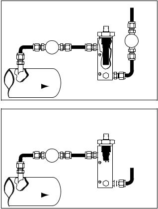
2.3.2 Extractive Installation
For extractive installations we recommend our sample system ESS, which may be equipped with a variety of features, such as: isolation valve, coalescing or particulate filter, pressure regulator, calibration sample injection or extraction port, pressure gauge, flow meter, weatherproof enclosure. Refer to the ESS literature for more information.
If the resources to make your own sample system are available, the following two diagrams may be used as a guideline to configure a simple system.
Exhaust
Safety shut-off Valve
Cell |
Regulator or |
Needle Valve |
Sample |
|
|
Main |
|
Extractive Installation, Sensor |
|
||
Gas Line |
|
Measuring at Line Pressure |
|
|
Regulator or Needle Valve
Sample Cell


Exhaust
Main |
|
Extractive Installation, Sensor |
Gas Line |
|
|
|
Measuring at Ambient Pressure |
|
|
|
It is generally recommended to measure at ambient pressure for the following reasons:
•The readings will not be affected by variations in line pressure.
•The risk of exposing the sensor to liquid water is significantly reduced.
•ppm readings are computed for a pressure of one atmosphere (1 bar); and have to be corrected using software in the instrument, or a pressure monograph, or calculator if the sensor is mea-
suring at different pressures.
If readings at line pressure are necessary, it is recommended to measure at ambient pressure and to use the instrument’s pressure compensation feature to calculate the dewpoint at line pressure. Refer to Viewing Dewpoint Mode section 3.4.4.1.
Please make sure that:
•The sample is taken from the upper surface of the main gas line. This avoids problems with contamination. The sample should be taken away from pipe line walls where flow rates may be low, and dewpoint changes may lag.
•For dewpoints dryer than -40°F, use stainless steel tubing only. Copper tubing is acceptable for dewpoints wetter than -40°F. Do not use plastic, rubber or tygon tubing under any circumstances, as measurements would be incorrect and/or response time slow due to water retention
6
Section 2: Sensor and Sampling Techniques
inside these materials.
•Try to run pipes to the sensor upwards, so that contaminants tend to fall back into the main line.
•Keep the length of the sample line to the sensor as short as possible.
•Use small diameter pipes (1/4” or 1/8” OD).
•Use sufficient flow rates (e.g. 1 l/min with 6 feet of 1/8” piping is adequate). The flow rate will influence the systems’ response time.
•Do not install any devices upstream of the sensor, such as other measuring systems, flow meters etc., which are not absolutely necessary as these are potential leak sources.
•Installation of a coalescing and / or particulate filter ahead of the sensor is desirable to prevent any liquid or particulate contamination of the sensor.
•If filters are used upstream of the sensor, make sure these contain non-hygroscopic filter materials only. Refer to Sample Gas Filter Considerations Appendix H.
•If pressure regulators, shut off valves etc. are used upstream of the sensor, make sure these do not contain rubber or other hygroscopic materials.
2.4 Mechanical Installation
The sensor probe has two thread sizes for mounting to the sample cavity where the dewpoint will be measured, see appendix C. Various optional fittings are available for direct connection into existing system openings, refer to appendix D. Ask your representative for a Sample Cell, if you do not have the ability to provide an appropriate sample cavity mounting. If the ¾”x16 thread is used then the sensor will seal against the wall of the sample cell with the provided Viton A O-ring. If the 14mm x 1.25 spark plug thread is used then an additional Viton gasket must be installed to provide the proper seal. Ask your representative for this gasket, it is available free of charge. To prevent any leaks, tighten the fitting into the sample cavity, with a 11/4” wrench, 1/8 turn past fin- ger-tight to assure metal-to-metal contact.
The sensor can be removed from the fitting by unscrewing it. Make sure that the sensor is securely fastened to the fitting (the tension washer should be compressed), so that it does not come loose during use.
7
8800 Series Trace Moisture Analyzer Instruction Manual
2.5 Troubleshooting unexpected readings
If erroneous readings are suspected on a newly acquired instrument, compare the serial number engraved on the sensor sintered filter, to the label on the instrument. The two should be the same; if they are not, the instrument may not be calibrated with the installed sensor. To troubleshoot other problems, identify the unexpected reading category in the following table, and consider the possible causes and appropriate diagnostic action and remedy.
Symptom |
|
Possible Cause |
Diagnostic/Remedy |
|
|
|
|
|
|
|
|
|
|
|
Condensation will occur if the temperature of the sample system, at any point is below |
Reading is not |
Condensation in sample system. |
(colder) the dewpoint temperature of the sample gas. Once having formed, the sample |
|
changing |
|
|
reaching the sensor will have a dewpoint equal to the temperature of the condensation, |
|
|
|
regardless of the dewpoint of the source gas. |
|
|
|
|
|
1. |
Water vapor in the system. |
It is usually more satisfactory to bleed a sample gas at atmospheric pressure through |
Slow Response |
2. Flow rate too low. |
the sensor sampling chamber, and to use 1/8” (3mm) o.d. sample pipe. |
|
|
3. |
Sample pipe too large and/or too long. |
|
|
4. |
Unsuitable sample pipe. |
|
|
5. |
Leaks. |
|
|
6. |
Hygroscopic materials in sample system |
See below re sample pipe material, also see section 2.3 |
|
|
|
|
Dry Reading |
SpanCheck™, wrongly set, or faulty Sensor. |
Verify SpanCheck™, or return sensor for full calibration to your representative. |
|
|
|
|
|
|
Leak in system or use of unsuitable pipe. |
Cure the leak, or replace unsuitable pipe with copper or stainless steel. Flexible con- |
|
Wet Reading |
|
|
nections should be made with PTFE pipe. NEVER use rubber or plastic pipe. |
|
|
|
|
|
Comparison of readings with manual cooled- |
This type of indicator reads about 10ºC dry at about -50ºC dewpoint due to tempera- |
|
|
mirror instrument. |
ture gradients within the device. The error increases at drier levels. |
|
|
|
|
|
Display Shows |
Prolonged exposure to wet gas. |
Dry down the sensor, install sensor in either a known dry gas stream i.e. instrument |
|
SAT |
|
|
quality air or dry nitrogen, or place sensor in a dry can or bottle of desiccant and seal |
|
|
|
the container from outside air (the shipping container is designed for this purpose) |
|
|
|
also see section 3.4.4.3.1 |
|
|
|
|
|
1. |
Instrument Failure |
Disconnect cable from input terminals, if the instrument still reads SHR the problem |
|
|
|
is with the instrument. However, if the instrument reads OPN then recconect the cable |
|
|
|
to the input terminals and check possible causes 2 or 3. |
|
|
|
|
Display Shows |
2.Short circuit on sensor cable or connections. |
Disconnect cable from sensor and if meter still reads SHR, cure the short circuit in the |
|
SHR |
|
|
cable or connections or replace cable; otherwise check the sensor. |
|
|
|
|
|
3.Short circuited sensor. |
Disconnect cable from sensor and note that the meter reading returns to OPN. Use a |
|
|
new sensor, or apply approximately 20V DC to the sensor MOMENTARILY with the |
||
|
|
|
sensor in a known dry condition. Polarity is not important, but the contact MUST be |
|
|
|
very brief or the sensor may be damaged. |
|
|
|
|
|
|
|
Short the SIG and SHIELD contacts of the sensor input terminal, if the instrument |
Display Shows |
1. |
Instrument failure. |
reads SHR the problem is in the cable or sensor, otherwise return the instrument for |
|
|
service. |
|
OPN. |
|
|
|
2. Open circuit on cable. |
Disconnect cable from sensor and short center pin of plug to the outer shell. If the dis- |
||
|
|
|
play still shows OPN, repair cable. |
|
|
|
|
|
3. |
Open circuit on sensor. |
Check sensor connection or replace sensor. |
|
|
|
|
For non-sensor related problems (e.g. no reading on instrument) refer to section 3.6
8
Section 3: Instrument
3. Instrument
3.1 Precautions using the 8800 Series Trace Moisture Analyzer
The 8800 Series Trace Moisture Analyzer uses state-of-the-art microelectronics to provide a compact full functioning instrument. The user should consider the following precautions when using any sensitive electronic device.
•Observe the appropriate electrical safety codes and regulations. Consult with National Electrical Code article 400, and/or other nationally or locally recognized procedures relevant to your installation. You will most probably require a disconnect switch, and power wiring. The power cord provided with the instrument is intended only for testing, it may not be used for a permanent field wired installation. This instrument is UL approved for field wiring.
•If weather proofing is required consult your representative for an optional enclosure. The 8800 Series Trace Moisture Analyzer is not intended for direct outdoor installation unless it is appropriately housed.
•Do not install the unit near heat sources such as radiators or air ducts.
•Do not install the unit in places subject to extreme mechanical vibration or shock. If this is not avoidable, use resilient mounting. If in doubt, call your representative.
3.1.1 Electromagnetic Compatibility Considerations
The 8800 Series Trace Moisture Analyzer has been designed and verified by testing to meet the requirements of the EC Council EMC Directive 89/336/EEC, for Industrial, Scientific & Medical equipment. The sensor ground is isolated from the AC ground, logic ground, 4-20mA loop return, etc.; however they are also shunted with a 0.1uf capacitor 1M Ohm resistor, and a 33V Transient Voltage Suppressor; this prevents electrostatic buildup, noise pick-up, and in conjunction with the internal fuse protects the instrument from over-voltage inputs. Please consider the following electromagnetic interference issues during installation:
•In order to provide an acceptable noise environment for the 8800 series Trace Moisture Analyzer or any other digital equipment in the proximity of switched inductive loads, it is recommended that there be varistors placed across the inductors to keep down the high voltage spikes during transitions.
•Any circuitry which is activated by relay contacts should account for the contact bounce, one simple debouncing method is placing a capacitor across the relay contacts.
•AC power wiring should be routed as far away from the 8800 Series Trace Moisture Analyzer and its wiring as practical.
9
8800 Series Trace Moisture Analyzer Instruction Manual
3.2 Instrument Technical Specifications
Enclosure: ......................... |
8800B tabletop or surface mount, watertight IP65 tested, and NEMA 12 tested |
|
|
8800A panel-mount, DIN 43700 dimensional standard, optional NEMA 12 type protection gasketing |
|
|
available |
|
Dimensions & Weight:...... |
8800B: 4.73” x 6.3” x 3.55”, 2.1 lbs (fully optioned) w/cables. |
|
|
8800A: 5.67” x 2.84” x 2.95” DIN 43700 standard, 1.3 lbs (fully optioned) w/cables. |
|
|
refer to appendix E for detailed dimensions |
|
Environmental Range: ...... |
Operating temperature of electronics: 14°F to 122°F (-10°C to 50°C) |
|
|
Storage temperature of electronics: -40°F to 176°F (-40°C to 80°C) |
|
|
Humidity: 0 to 90% RH non-condensing |
|
|
Altitude: 0 to 6500 feet (2000 meters) |
|
Mains Supply Voltage:...... |
100 to 250VAC autoranging, 50/60Hz, 10VA, internal 0.5A, 250V fast acting fuse. |
|
|
Optionally the instrument may be configured with DC power capability: 15 to 30VDC 0.5A. |
|
Electrical connections:...... |
21 contact pluggable screw terminal block, 1.3mm diameter pins on 5mm centers. |
|
Wiring requirements: ........ |
For AC Power: 18AWG or heavier wire, an external means for disconnecting the power source is |
|
|
required to meet National Electrical Code requirements. |
|
|
For Sensor signal: RG58 coaxial cable, or RG6 for cable longer than 100’. A 6 foot cable is provided as |
|
|
a standard, other lengths ordered as options. When changing cable, refer to cable compensation section. |
|
Input resolution:................ |
0.1°C dewpoint. |
|
Indicators: ......................... |
3.5 digit backlit LCD with custom legends, audible indicator. |
|
Engineering units: ............. |
°C,°F, PPM, LBS H O/mm scf,gm H O/m3. |
|
|
2 |
2 |
Controls:............................ |
Four push buttons, user’s selections are stored in EEPROM. |
|
Outputs:............................. |
Analog: voltage by order or current user selectable 4-20mA or 0/24mA. Linear to the selected engi- |
|
|
neering units, the range is programmable. Output resolution is 0.1°C dewpoint, linearity 1%, max load |
|
|
resistance 500 Ohms. |
|
|
Digital RS-232C (9600,8,E,1), can interface to a Personal Computer or other RS-232 device. |
|
Alarm relay contacts: ........ |
Ordinary use, explosion-proof housed, and safe area instruments: 10A, 250VAC or 30VDC. |
|
|
Intrinsically Safe Div 2 instruments use hermetically sealed relays: 3A, 120VAC |
|
Isolation: ........................... |
Sensor is isolated from power ground, analog output and RS-232, but they are shunted with a 33V tran- |
|
|
sorb, a 1M Ohm resistor and 0.1uF capacitor. Refer to Electrical Connections section. |
|
Approvals/Classifications: CE for electromagnetic compatibility, accredited laboratory tested and certified |
||
|
UL and cUL for ordinary field wired use |
|
|
Intrinsically Safe configurations: |
for NEC standard IS installations UL, |
|
|
for CENELEC standard IS installations DEMKO, |
|
|
refer to instrument labeling |
10
Section 3: Instrument
3.3 Installation
3.3.1 Instrument Mechanical Installation
The 8800 Series Trace Moisture Analyzer is available in several different physical configurations. Please follow the instructions below, which describe the instrument being installed. The sensor installation is discussed in Section 2: Sensor and Sampling Techniques.
3.3.1.1 8800A (DIN43700) Enclosure Installation
The standard 8800A Trace Moisture Analyzer is provided with two clip-on compression panel mounting brackets. These brackets allow the user to mount and secure the instrument onto a properly cutout panel (137mm x 67mm). Consult with drawing in appendix E, for all relevant dimensions. Installation is accomplished by attaching 2 clips, one on each side of instrument, and inserting the instrument into the panel cutout. Pressure must be applied along edges of instrument until it is firmly seated.
The 8800A Trace Moisture Analyzer may be ordered with an environmental seal option. This option provides a gasket (installed at the factory) to seal the face plate to the enclosure box, and a gasket (to be installed by the user) to seal the enclosure box to the user’s mounting panel. To achieve a good environmental seal the 8800A Trace Moisture Analyzer must be mounted onto a rigid flat panel with a cutout according to the specified dimensions, using the provided panel gasket and all four provided mounting brackets. The instructions listed below should be followed.
•If the clip-on mounting brackets are installed on the instrument enclosure, remove them.
•Make sure that the panel gasket is flat and even around the box bezel. Handle the gasket carefully as not to tear it.
•Insert the box into the user’s panel cutout, consult with drawing in appendix E for proper panel cutout dimensions.
•Attach all four mounting brackets to the instrument enclosure from the rear of the panel, make sure they are fully locked in.
•Use a screwdriver to tighten the mounting bracket screws, all four screws should be tightened uniformly, the panel gasket should be compressed.
3.3.1.2 8800B (IP65) Enclosure Installation
The instrument can be installed as a wall or panel surface mount, by making use of four screw holes on the back (bottom) of the instrument enclosure. Open the instrument cover for access to these screw holes. They are located at the corners of the enclosure and outside of the NEMA seal. Do not drill other mounting holes, as you may compromise the seal. Refer to Appendix E for all relevant dimensions.
11
8800 Series Trace Moisture Analyzer Instruction Manual
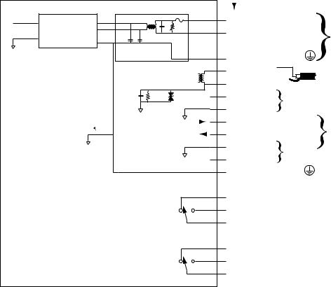
3.3.2 Electrical Connections
All connections are made via a 21 contact, pluggable screw terminal block referred to as P1.
Pluggable Block Terminals 
Power Supply Module |
0.5A 250V |
1 |
AC LIVE |
|
|
4.3mH |
|
|
|||
|
0.1uf |
|
|
|
|
|
275VAC |
2 |
AC NEUTRAL |
AC Power Input: |
|
|
|
||||
0.0047uf |
0.0047uf |
3 |
Not Connected |
100 to 250VAC, 50/60Hz, 10VA |
|
|
|||||
|
|
|
|||
RFI filter board |
4 |
AC GROUND |
|
||
|
Sensor |
5 |
SIG-IN |
white |
|
|
|
SENSOR CABLE |
|||
|
Measuring |
6 |
SIG-RET |
|
|
|
Circuitry |
black |
|
||
0.1uf |
1M Ohm 33V 400W |
7 |
A-OUT |
Analog Output 4/20mA or 0/24mA or Voltage * |
|
|
|
||||
Logic ground and AC Power |
|
8 |
A-RET |
|
|
|
|
|
|
|
|
ground are connected for safety |
|
|
|
|
RS 232 I/O * |
and electromagnetic |
|
9 |
TxD |
|
|
interference considerations |
|
|
|||
|
|
10 |
RxD |
|
CAUTION: Connecting the RS-232C interface |
|
|
|
on instruments which do not have the option |
||
|
|
11 |
RET |
|
|
|
|
|
installed, will damage the instrument. |
||
|
|
+DC power 15V OUTPUT and/or 15-30V INPUT* 0.5A |
|||
|
|
12 |
PS+ |
||
|
|
|
|
||
|
|
13 |
AC GROUND |
|
|
|
|
14 |
Not Connected |
|
|
|
|
15 |
NC |
|
|
|
LO |
16 |
NO |
|
|
|
17 |
C |
|
|
|
|
|
|
|
||
Ordinary relay contacts: 10A, 250VAC or 30VDC |
ALARMS* |
18 |
Not Connected |
|
|
Hermetically Sealed relay contacts: 3A, 120VAC |
|
||||
|
|
19 |
NC |
|
|
|
HI |
20 |
NO |
|
|
|
21 |
C |
|
|
|
|
|
|
|
||
Instrument Circuit board
Note: * Options will function only if they are installed
Cable access to the 8800B enclosure is through three ports (refer to appendix E), which maintain the NEMA integrity:
•One 1/2” NPT conduit fitting, may be used for high or low voltage connections. This port is intended for the power and high voltage relay wiring.
•Two watertight cable grips located at the bottom of the instrument: for low voltage wiring only such as sensor, analog output, RS-232, or relays when used with low voltages. They accommodate cables with diameters 0.196” to 0.315”. To install a cable, loosen the nut, feed the cable through the grip and tighten the nut again. Unused cable grips should be plugged to maintain the integrity of the enclosure.
3.3.2.1 Connecting Power
The 8800 Series Trace Moisture Analyzer is typically provided to be field wired to operate from AC Mains Power of 100 to 250VAC, 50/60Hz, 10VA, the instrument has an internal 0.5A, 250V fast acting fuse. However the 8800 Series Trace Moisture Analyzer can also be optionally ordered
12
Section 3: Instrument
to operate from 15 to 30 VDC 0.5A, with an internal 0.5A fast acting fuse. Please follow the appropriate installation procedures in the paragraphs below according to the electrical power option on your instrument. Do not connect to AC power without a proper ground connection.
For Intrinsically Safe installations, first make sure that the equipment is qualified for the particular installation, it should have a label specifying the certifications and the approving agency. Then follow the appropriate control drawing as well as the instructions in the relevant paragraphs in this manual.
3.3.2.1.1 AC Mains Electrical Power Connection
The 8800 Series Trace Moisture Analyzer is provided with a 6 foot (2 meter) internationally approved AC power cord, terminated with a connector according to the ordered option. This cable is connected to the pluggable screw terminal block; however it is provided strictly as a means of testing the instrument, it should not be used in the final installation. The 8800 Series Trace Moisture Analyzer is intended as a field wired instrument permanently connected and installed according to the local, nationally recognized procedures for equipment of this type and stated power requirements. For North American installations use UL 62 and/or CSA C22.2 No 49, 18AWG cable with black, white, and green color codes. For European and other international installations use CENELEC harmonized type cable, with 0.82mm wire size or equivalent 10 amp use, with brown, light blue, and green/yellow stripe color codes. The power wiring must be connected to the pluggable screw terminals marked AC LIVE (#1), AC NEUTRAL (#2), and AC GROUND (#4). A switch or circuit breaker shall be included in the installation. It shall be in close proximity to the equipment and within easy reach of the operator. It shall be marked as the disconnecting device for the instrument. For the 8800B use the 1/2” NPT conduit fitting as the power cable access, do not use the cable grips they are for low voltage use only.
3.3.2.1.2 Low Voltage DC Powered Option - Electrical Power Connection
When an 8800 Series Trace Moisture Analyzer is configured with the low voltage DC power option, it can be powered by applying 15 to 30 VDC 0.5A, to the PS+ (#12) and RET (#11) pluggable screw terminals. The positive supply must be connected to PS+, while the negative or ground to RET. The AC terminals must not be connected.
3.3.2.2 Sensor Connection
The sensor input terminals are labeled “SIG-IN” (#5) for the center core of the coaxial sensor cable, and “SIG RET” (#6) for the outside braid of the cable. Factory supplied coaxial cables have a BNC connector at one end to mate to the sensor, and pigtails at the other end to be placed in the screw terminals of P1, the black pigtail is the braid and should be connected to the terminal marked “SIG RET”. The coaxial cable can be as much as 3,000 ft. long, however if the cable is changed for a longer or shorter one the instrument must be compensated for the new cable (see section 3.4.5 -11). The instrument is properly compensated for the cable supplied from the factory. Consult your representative for obtaining the proper cable.
3.3.2.3 Wiring the Alarm Contacts
The optional alarm relay contacts are located on the terminal strip P1. The terminal strips are marked to indicate wipers and normally open and normally closed contacts, of the two independent relays corresponding to the HI and LO alarms. The relay contacts are rated at 10A 250VAC
13
8800 Series Trace Moisture Analyzer Instruction Manual
or 30VDC, instruments for use in division 2 Hazardous Areas have hermetically sealed relays rated at 3A 125VAC. Use wiring appropriate for the voltage and current that will be switched by the relays. Also see section 1.3 for EMI considerations. Keep in mind that the relay polarity is programmable thus wiring should be designed to provide a fail safe operation in case of power failure. See section 3.4.4.2. Also note that while viewing the dewpoint, the display will flash HI and/or LO as necessary to indicate that the corresponding alarm relay is de-energized. Specially ordered instruments may have a third alarm, refer to the supplied addendum for relay contact rating, pinouts and user interface issues.
3.3.2.4 Interfacing to the Analog Output
The optional Analog Output may be a voltage or current, depending on the ordered configuration. The Analog Output signal is provided on the P1 connector, when wiring please observe the polarity indications. The positive terminal is on pin #7 it is labeled “A-OUT” and the negative is on pin #8 it is labeled “A-RET”. The ground of the Analog Output is connected to the frame (AC power) ground but it is isolated from the sensor ground, see section 3.1.1.
Instruments ordered with Voltage output, are configured at the factory with appropriate resistors across the current loop output such that when operated in the 0-24mA mode they produce the desired voltage.
The current loop is capable of driving loads from 0Ω to 500Ω and the user may select to operate it as 0-24mA or as 4-20mA (refer to 3.4.5-6). The output is linearly proportional to the selected engineering units. The output may be scaled such that it spans only a portion of the full range of the sensor, this feature may be useful in cases where a higher resolution output is required over a narrow dewpoint range, or vise versa. To verify or change the current loop configuration and scaling follow the instructions in the set-up mode section 3.4.5 - 6,7,8&9.
After hooking up the current loop output, it can be forced to its low, mid and high points by following the instructions in section 3.4.5 - 7. This procedure may be helpful in testing the connection and setting-up the termination equipment.
14
Section 3: Instrument
3.3.2.5 Interfacing to the RS-232 option
The optional RS-232C interface is provided on the P1 connector. The configuration is 9600 baud, Even Parity, 8 Bits, 1 Stop, all received characters are echoed. The ground of the RS-232C interface is connected to the frame (AC power) ground however it is isolated from the sensor ground, see section 3.1.1.
To connect the instrument to a Personal Computer a 3 conductor cable is required; with wires to be placed in the screw terminals of the 8800 Series Trace Moisture Analyzer at one end, and with either a DB9 or DB25 female connector at the other end:
Signal Name |
instrument P1 |
DB9 pin |
or DB25 pin |
||
pin # |
|||||
|
|
|
|
||
|
|
|
|
||
|
|
|
|
|
|
Transmit Data |
9 TXD or Tx |
2 |
|
3 |
|
|
|
|
|
|
|
Receive Data |
10 RXD or Rx |
3 |
|
2 |
|
|
|
|
|
|
|
Signal Ground |
11 GND |
5 |
|
7 |
|
|
|
|
|
|
|
RTS |
n.c. |
7 |
|
4 |
|
|
|
|
|
|
|
CTS |
n.c. |
8 |
|
5 |
|
|
|
|
|
|
|
DTR |
n.c. |
4 |
|
20 |
|
|
|
|
|
|
|
DSR |
n.c. |
6 |
|
6 |
|
|
|
|
|
|
|
Note that some Personal Computer Programs may require that RTS & CTS and/or DTR & DSR are jumpered for proper operation. This jumpering may be accomplished at the DB9 or DB25 connector.
CAUTION: Connecting the RS-232C interface on instruments which do not have the option installed, will damage the instrument.
Refer to appendix K for details on the protocol used on the RS-232C interface.
3.4 Operating the Instrument
3.4.1 Starting up
The instrument is ready for use as soon as the power cabling is connected. When power is applied the instrument will initialize its program and for a moment display XEN, then it will enter the Operating State. If the MODE button is held pressed while the instrument is performing its power-up initialization, it will enter the Set-Up State, which allows the user to select setup variables of the instrument.
15
 Loading...