


Thermal Conductivity Analyzer
OPERATING INSTRUCTIONS FOR
Model 2000A-EU
Thermal Conductivity Analyzer
DANGER
HIGHLY TOXIC AND OR FLAMMABLE LIQUIDS OR GASES MAY BE PRESENT IN THIS MONITORING SYSTEM.
PERSONAL PROTECTIVE EQUIPMENT MAY BE REQUIRED WHEN SERVICING THIS SYSTEM.
HAZARDOUS VOLTAGES EXIST ON CERTAIN COMPONENTS INTERNALLY WHICH MAY PERSIST FOR A TIME EVEN AFTER THE POWER IS TURNED OFF AND DISCONNECTED.
ONLY AUTHORIZED PERSONNEL SHOULD CONDUCT MAINTENANCE AND/OR SERVICING. BEFORE CONDUCTING ANY MAINTENANCE OR SERVICING CONSULT WITH AUTHORIZED SUPERVISOR/ MANAGER.
P/N M66182 07/22/05
ECO # 05-0131
i
 Teledyne Analytical Instruments

Model 2000A-EU
Copyright © 1999 Teledyne Analytical Instruments
All Rights Reserved. No part of this manual may be reproduced, transmitted, transcribed, stored in a retrieval system, or translated into any other language or computer language in whole or in part, in any form or by any means, whether it be electronic, mechanical, magnetic, optical, manual, or otherwise, without the prior written consent of Teledyne Analytical Instruments, 16830 Chestnut Street, City of Industry, CA 91749-1580.
Warranty
This equipment is sold subject to the mutual agreement that it is warranted by us free from defects of material and of construction, and that our liability shall be limited to replacing or repairing at our factory (without charge, except for transportation), or at customer plant at our option, any material or construction in which defects become apparent within one year from the date of shipment, except in cases where quotations or acknowledgements provide for a shorter period. Components manufactured by others bear the warranty of their manufacturer. This warranty does not cover defects caused by wear, accident, misuse, neglect or repairs other than those performed by Teledyne or an authorized service center. We assume no liability for direct or indirect damages of any kind and the purchaser by the acceptance of the equipment will assume all liability for any damage which may result from its use or misuse.
We reserve the right to employ any suitable material in the manufacture of our apparatus, and to make any alterations in the dimensions, shape or weight of any parts, in so far as such alterations do not adversely affect our warranty.
Important Notice
This instrument provides measurement readings to its user, and serves as a tool by which valuable data can be gathered. The information provided by the instrument may assist the user in eliminating potential hazards caused by his process; however, it is essential that all personnel involved in the use of the instrument or its interface, with the process being measured, be properly trained in the process itself, as well as all instrumentation related to it.
The safety of personnel is ultimately the responsibility of those who control process conditions. While this instrument may be able to provide early warning of imminent danger, it has no control over process conditions, and it can be misused. In particular, any alarm or control systems installed must be tested and understood, both as to how they operate and as to how they can be defeated. Any safeguards required such as locks, labels, or redundancy, must be provided by the user or specifically requested of Teledyne at the time the order is placed.
Therefore, the purchaser must be aware of the hazardous process conditions. The purchaser is responsible for the training of personnel, for providing hazard warning methods and instrumentation per the appropriate standards, and for ensuring that hazard warning devices and instrumentation are maintained and operated properly.
Teledyne Analytical Instruments, the manufacturer of this instrument, cannot accept responsibility for conditions beyond its knowledge and control. No statement expressed or implied by this document or any information disseminated by the manufacturer or its agents, is to be construed as a warranty of adequate safety control under the user’s process conditions.
ii

Thermal Conductivity Analyzer
Specific Model Information
The instrument for which this manual was supplied may incorporate one or more options not supplied in the standard instrument. Commonly available options are listed below, with check boxes. Any that are incorporated in the instrument for which this manual is supplied are indicated by a check mark in the box.
Instrument Serial Number: _______________________
Options Available with Order:
2000A-C: |
Auto Calibration valves (zero/span) built-in gas selector panel |
|
and control valves are electronically controlled to provide |
|
synchronization with the analyzer’s operations. |
2000A-G: |
Stainless steel cell block with nickel filaments and Stainless |
|
Steel fittings and tubing. |
2000A-H: |
Stainless steel cell block with gold filaments for corrosive gas |
|
streams and Stainless Steel fittings and tubing. |
2000A-K: |
19" Rack Mount available with either one or two analyzers |
|
Control Units installed and ready to mount in a standard rack |
2000A-L: |
Gas selector panel consisting of sample/ref flow meters and |
|
control valves for metering input of sample/calibrations |
|
support gases |
2000A-R: |
Sealed reference cell (application dependent, contact factory). |
2000A-N: |
220 VAC operation. |
iii
Model 2000A-EU
Model 2000A-EU complies with all of the requirements of the Commonwealth of Europe (CE) for Radio Frequency Interference, Electromagnetic Interference (RFI/EMI), and Low Voltage Directive (LVD).
The following International Symbols are used throughout the Instruction Manual for your visual and immediate warnings and when you have to attend CAUTION while operating the instrument:
STAND-BY, Instrument is on Stand-by, but circuit is active
GROUND
Protective Earth
CAUTION, The operator needs to refer to the manual for further information. Failure to do so may compromise the safe operation of the equipment.
CAUTION, Risk of Electric Shock
DANGER
COMBUSTIBLE GAS USAGE WARNING
This is a general purpose instrument designed for usage in a nonhazardous area. It is the customer's responsibility to ensure safety especially when combustible gases are being analyzed since the potential of gas leaks always exist.
The customer should ensure that the principles of operating of this equipment is well understood by the user. Misuse of this product in any manner, tampering with its components, or unauthorized substitution of any component may adversely affect the safety of this instrument.
Since the use of this instrument is beyond the control of Teledyne, no responsibility by Teledyne, its affiliates, and agents for damage or injury from misuse or neglect of this equipment is implied or assumed.
iv

Thermal Conductivity Analyzer
|
|
|
|
|
|
|
|
|
|
|
|
|
|
Table of Contents |
|
|
|
|
|
|
|
|
|
|
|
|
|
|
|
1 Introduction |
|
|
|||
1.1 |
Overview ........................................................................ |
1-1 |
|
||
1.2 |
Typical Applications ....................................................... |
1-2 |
|
||
1.3 |
Main Features of the Analyzer ....................................... |
1-2 |
|
||
1.4 |
Model Designations ....................................................... |
1-3 |
|
||
1.5 |
Front Panel (Operator Interface) ..................................... |
1-3 |
|
||
1.6 |
Recognizing Difference Between LCD & VFD ............... |
1-5 |
|
||
1.7 |
Rear Panel (Equipment Interface) .................................. |
1-5 |
|
||
1.8 |
Gas Connections ........................................................... |
1-7 |
|
||
2 Operational Theory |
|
|
2.1 |
Introduction .................................................................... |
2-1 |
2.2 |
Sensor Theory ............................................................... |
2-1 |
2.2.1 |
Sensor Configuration ............................................... |
2-1 |
||
2.2.2 |
Calibration ............................................................... |
2-2 |
||
2.2.3 Effects of Flowrate and Gas Density ........................ |
2-3 |
|||
2.2.4 Measurement Results .............................................. |
2-3 |
|||
2.3 |
Electronics and Signal Processing ................................ |
2-3 |
||
2.4 |
Temperature Control ...................................................... |
2-5 |
||
3 Installation |
|
|
||
3.1 |
Unpacking the Analyzer ................................................. |
3-1 |
||
3.2 |
Mounting the Analyzer ................................................... |
3-1 |
||
3.3 |
Electrical Connections (Rear Panel) .............................. |
3-3 |
||
3.3.1 |
Primary Input Power ............................................... |
3-4 |
||
3.3.2 |
Primary Input Power ............................................... |
3-4 |
||
3.3.3 50-Pin Equipment Interface Connector .................. |
3-4 |
|||
|
3.3.3.1 |
Analog Outputs .............................................. |
3-5 |
|
|
3.3.3.2 |
Alarm Relays ................................................. |
3-6 |
|
|
3.3.3.3 Digital Remote Cal Inputs .............................. |
3-7 |
||
|
3.3.3.4 |
Range ID Relays ........................................... |
3-9 |
|
|
3.3.3.5 |
Network I/O .................................................... |
3-9 |
|
|
3.3.3.6 |
Remote Valve Connector ............................... |
3-9 |
|
3.3.4 |
RS-232 Port ........................................................... |
3-10 |
||
3.4 |
Gas Connections ........................................................... |
3-11 |
||
3.4.1 |
Sample System Design ......................................... |
3-13 |
||
3.4.2 Pressure and Flow Rate Regulation ...................... |
3-13 |
|||
3.4.3 |
VENT Exhaust ....................................................... |
3-14 |
||
3.4.4 |
SAMPLE Gas......................................................... |
3-14 |
||
v

Model 2000A-EU
|
|
|
|
|
|
|
|
|
|
3.4.5 |
................................................REFERENCE Gas |
3-15 |
||
3.4.6 |
ZERO Gas ............................................................. |
3-15 |
||
3.4.7 |
SPAN Gas .............................................................. |
3-15 |
||
3.5 |
Testing the System ......................................................... |
3-16 |
||
3.6 |
Warm Up at Power Up .................................................... |
3-16 |
||
4 Operation |
|
|
||
4.1 |
Introduction .................................................................... |
4-1 |
||
4.2 |
Using the Data Entry and Function Buttons ................... |
4-1 |
||
4.3 |
The System Function ..................................................... |
4-4 |
||
4.3.1 |
Setting the Display ................................................. |
4-5 |
||
4.3.2 Setting up an Auto-Cal ........................................... |
4-5 |
|||
4.3.3 |
Password Protection .............................................. |
4-6 |
||
|
4.3.3.1 |
Entering the Password ................................... |
4-7 |
|
|
4.3.3.2 Installing or Changing the Password ............. |
4-7 |
||
4.3.4 |
Logging Out ........................................................... |
4-9 |
||
4.3.5 |
System Self-Diagnostic Test .................................. |
4-9 |
||
4.3.6 |
The Model Screen ................................................. |
4-10 |
||
4.3.7 Checking Linearity with ALGORITHM ................... |
4-10 |
|||
4.4 |
The Zero and Span Functions ....................................... |
4-11 |
||
4.4.1 |
Zero Cal ................................................................. |
4-12 |
||
|
4.4.1.1 |
Auto Mode Zeroing ........................................ |
4-12 |
|
|
4.4.1.2 |
Manual Mode Zeroing .................................... |
4-13 |
|
|
4.4.1.3 |
Cell Failure .................................................... |
4-14 |
|
4.4.2 |
Span Cal ................................................................ |
4-14 |
||
|
4.4.2.1 |
Auto Mode Spanning ..................................... |
4-15 |
|
|
4.4.2.2 |
Manual Mode Spanning ................................. |
4-15 |
|
4.5 |
The Alarms Function ...................................................... |
4-16 |
||
4.6 |
The Range Function ...................................................... |
4-18 |
||
4.6.1 Manual (Select/Define Range) Screen .................. |
4-19 |
|||
4.6.2 Auto (Single Application) Screen ........................... |
4-19 |
|||
4.6.3 |
Precautions ............................................................ |
4-21 |
||
4.7 |
The Analyze Function .................................................... |
4-22 |
||
4.8 |
Programming ................................................................. |
4-22 |
||
4.8.1 The Set Range Screen .......................................... |
4.23 |
|||
4.8.2 The Curve Algorithm Screen ................................. |
4-25 |
|||
|
4.8.2.1 |
Checking the Linearization ............................ |
4-25 |
|
|
4.8.2.2 |
Manual Mode Linearization ........................... |
4-26 |
|
|
4.8.2.3 |
Auto Mode Linearization ................................ |
4-27 |
|
4.9 |
Special Function Setup .................................................. |
4-28 |
||
4.9.1 |
Output Signal Reversal .......................................... |
4.28 |
||
vi

Thermal Conductivity Analyzer
|
|
|
|
|
|
|
|
4.9.2 |
......................................Special - Inverting Output |
4-29 |
|
4.9.3 |
Special - Polarity Coding ....................................... |
4.29 |
|
4.9.4 Special - Nonlinear Application Gain Preset.......... |
4-29 |
||
Maintenance |
|
||
5.1 |
Routine Maintenance ..................................................... |
5-1 |
|
5.2 |
System Self Diagnostic Test ........................................... |
5-1 |
|
5.3 |
VFD Display .................................................................. |
5-2 |
|
5.4 |
Fuse Replacement......................................................... |
5-2 |
|
5.5 |
Major Internal Components ............................................ |
5-3 |
|
5.6 |
Cell, Heater, and/or Thermistor Replacement ................ |
5-5 |
|
5.6.1 Removing the Cell Compartment........................... |
5-5 |
||
5.6.2 Removing and Replacing the Cell Block ............... |
5-6 |
||
5.6.3 Removing the Heater and/or Thermocouple .......... |
5-7 |
||
5.7 |
Cleaning ........................................................................ |
5-4 |
|
5.8 |
Phone Numbers ............................................................. |
5-5 |
|
Appendix |
|
|
|
A-1 |
Specifications ................................................................ |
A-1 |
|
A-2 |
Recommended 2-Year Spare Parts List ......................... |
A-3 |
|
A-3 |
Drawing List ................................................................... |
A-4 |
|
A-4 |
19-Inch Relay Rack Panel Mount ................................... |
A-4 |
|
A-5 |
Calibration Procedure for TG Application........................... |
A-5 |
|
vii

Model 2000A-EU
viii
Thermal Conductivity Analyzer |
Introduction 1 |
|
|
|
|
|
|
|
|
|
|
Introduction
1.1Overview
The Analytical Instruments Model 2000 Thermal Conductivity Analyzer is a versatile microprocessor-based instrument for measuring a component gas in a background gas, or in a specific mixture of background gases. 2000A-EU Analyzer complies with all of the requirements of the Comonwealth of Europe (CE) for Radio Frequency Interference and Electromagnetic Interfaces (RFI/EMI) protection. It compares the thermal conductivity of a sample stream with that of a reference gas of known composition. The 2000 can—
•measure the concentration of one gas in a mixture of two gases.
•measure the concentration of a gas in a specific mixture of background gases.
•measure the purity of a sample stream containing a single impurity or a mixture of impurities.
The standard 2000 is preprogrammed with automatic linearization algorithms for a large number of gases and gas mixtures. The factory can add to this data base for custom applications, or the sophisticated user can add his own unique application.
This manual covers the Model 2000A-EU General Purpose flushpanel and rack-mount units only. These units are for indoor use in a nonhazardous environment.
Many of the Model 2000 features covered in this manual are optional, selected according to the customers specific application. Therefore, the user will find much here that does not apply to his instrument. This is unavoidable due to the number of possible combinations of features available. We have endeavored to make the manual as usable and convenient as possible, in light of this flexibility.
Teledyne Analytical Instruments |
1-1 |

1 Introduction |
Model 2000A-EU |
|
|
|
|
|
|
|
|
|
|
1.2Typical Applications
A few typical applications of the Model 2000 are:
•Power Generation
•Air liquefaction
•Chemical reaction monitoring
•Steel manufacturing and heat treating
•Petrochemical process control
•Quality assurance
•Refrigeration and storage
•Gas proportioning control.
1.3Main Features of the Analyzer
The main features of the Model 2000 Thermal Conductivity Analyzer include:
•Three independent, user definable, analysis ranges allow up to three different gas applications with one concentration range each, or up to three concentration ranges for a single gas application, or any combination.
•Special recalibration range for multiple applications. Recalibrating one, recalibrates all.
•Automatic, independent linearization for each range.
•Auto Ranging allows analyzer to automatically select the proper preset range for a given single application. Manual override allows the user to lock onto a specific range of interest.
•RS-232 serial digital port for use with a computer or other digital communications device.
•Two adjustable concentration alarms and a system failure alarm.
•Extensive self-diagnostic testing, at startup and on demand.
•A 2-line alphanumeric display screen, driven by microprocessor electronics, that continuously prompts and informs the operator.
•High resolution, accurate indication of target or impurity gas concentration from large, bright, meter readout. (0-9999 ppm through 0-100 % depending on types of gas involved.)
•Standard, proven sensor cell design.
•Wide range of custom applications, ranges, and linearization.
1-2 |
Teledyne Analytical Instruments |
Thermal Conductivity Analyzer |
Introduction 1 |
|
|
|
|
|
|
|
|
|
|
•Microprocessor based electronics: 8-bit CMOS microprocessor with 32 kB RAM and 128 kB ROM.
•Auto and remote calibration capabilities.
•CE Mark Certified.
•Four analog outputs: two for measurement (0–1 V dc and Isolated 4–20 mA dc) and two for range identification.
•Compact and versatile design: Small footprint, yet internal components are accessible.
1.4Model Designations
The Model 2000A-EU is ordinarily custom programmed at the factory to fit the customer’s application. Many parameters, including the number of channels, the gas application, the materials specification of the sampling system, and others, are options. The most common options, are covered in this manual. See the Specific Model Information checklist in the front pages of this manual for those that apply to your Model 2000A analyzer. Some standard models that are not covered in this manual are listed here.
Models 2000B: NEMA-4, bulkhead mounted enclosure for general purpose, nonhazardous environments.
Models 2010: Split architecture models using a sealed explosion-proof enclosure for the Analysis Unit and a general purpose remote Control Unit for installation in a safe area.
Models 2020: Both the analysis section and control unit are in a single explosion proof enclosure.
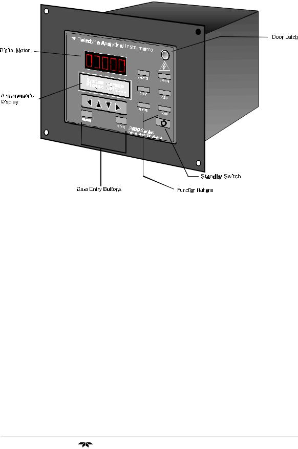
1.5Front Panel (Operator Interface)
The 2000A is housed in a rugged metal case with all controls and displays accessible from the front panel. See Figure 1-1. The front panel has thirteen buttons for operating the analyzer, a digital meter, and an alphanumeric display. They are described briefly here and in detail in the Operations chapter of this manual.
Function Keys: Six touch-sensitive membrane switches are used to change the specific function performed by the analyzer:
•Analyze Perform analysis for target-gas content of a sample
gas.
Teledyne Analytical Instruments |
1-3 |
1 Introduction |
|
|
|
|
|
|
|
|
|
|
|
|
|
|
|
|
|
|
|
|
|
|
|
|
|
Model 2000A-EU |
||||||||||||||
|
|
|
|
|
|
|
|
|
|
|
|
|
|
|
|
|
|
|
|
|
|
|
|
|
|
|
|
|
|
|
|
|
|
|
|
|
|
|
|
|
|
|
|
|
|
|
|
|
|
|
|
|
|
|
|
|
|
|
|
|
|
|
|
|
|
|
|
|
|
|
|
|
|
|
|
|
|
|
|
|
|
|
|
|
|
|
|
|
|
|
|
|
|
|
|
|
|
|
|
|
|
|
|
|
|
|
|
|
|
|
|
|
|
|
|
|
|
|
|
|
|
|
|
|
|
|
|
|
|
|
|
|
|
|
|
|
|
|
|
|
|
|
|
|
|
|
|
|
|
|
|
|
|
|
|
|
|
|
|
|
|
|
|
|
|
|
|
|
|
|
|
|
|
|
|
|
|
|
|
|
|
|
|
|
|
|
|
|
|
|
|
|
|
|
|
|
|
|
|
|
|
|
|
|
|
|
|
|
|
|
|
|
|
|
|
|
|
|
|
|
|
|
|
|
|
|
|
|
|
|
|
|
|
|
|
|
|
|
|
|
|
|
|
|
|
|
|
|
|
|
|
|
|
|
|
|
|
|
|
|
|
|
|
|
|
|
|
|
|
|
|
|
|
|
|
|
|
|
|
|
|
|
|
|
|
|
|
|
|
|
|
|
|
|
|
|
|
|
|
|
|
|
|
|
|
|
|
|
|
|
|
|
|
|
|
|
|
|
|
|
|
|
|
|
|
|
|
|
|
|
|
|
|
|
|
|
|
|
|
|
|
|
|
|
|
|
|
|
|
|
|
|
|
|
|
|
|
|
|
|
|
|
|
|
|
|
|
|
|
|
|
|
|
|
|
|
|
|
|
|
|
|
|
|
|
|
|
|
|
|
|
|
|
|
|
|
|
|
|
|
|
|
|
|
|
|
|
|
|
|
|
|
|
|
|
|
|
|
|
|
|
|
|
|
|
|
|
|
|
|
|
|
|
|
|
|
|
|
|
|
|
|
|
|
|
|
|
|
|
|
|
|
|
|
|
|
|
|
|
|
|
|
|
|
|
|
|
|
|
|
|
|
|
|
|
|
|
|
|
|
|
|
|
|
|
|
|
|
|
|
|
|
|
|
|
|
|
|
|
|
|
|
|
|
|
|
|
|
|
|
|
|
|
|
|
|
|
|
|
|
|
|
|
|
|
|
|
|
|
|
|
|
|
|
|
|
|
|
|
|
|
|
|
|
|
|
|
|
|
|
|
|
|
|
|
|
|
|
|
|
|
|
|
|
|
|
|
|
|
|
|
|
|
|
|
|
|
|
|
|
|
|
|
|
|
|
|
|
|
|
|
|
|
|
|
|
|
|
|
|
|
|
|
|
|
|
|
|
|
|
|
|
|
|
|
|
|
|
|
|
|
|
|
|
|
|
|
|
|
|
|
|
|
|
|
|
|
|
|
|
|
|
|
|
|
|
|
|
|
|
|
|
|
|
|
|
|
|
|
|
|
|
|
|
|
|
|
|
|
|
|
|
|
|
|
|
|
|
|
|
|
|
|
|
|
|
|
|
|
|
|
|
|
|
|
|
|
|
|
|
|
|
|
|
|
|
|
|
|
|
|
|
|
|
|
|
|
|
|
|
|
|
|
|
|
|
|
|
|
|
|
|
|
|
|
|
|
|
|
|
|
|
|
|
|
|
|
|
|
|
|
|
|
|
|
|
|
|
|
|
|
|
|
|
|
|
|
|
|
|
|
|
|
|
|
|
|
|
|
|
|
|
|
|
|
|
|
|
|
|
|
|
|
|
|
|
|
|
|
|
|
|
|
|
|
|
|
|
|
|
|
|
|
|
|
|
|
|
|
Figure 1-1: Model 2000A Front Panel
•System Perform system-related tasks (described in detail in
chapter 4, Operation.).
•Span Span calibrate the analyzer.
•Zero Zero calibrate the analyzer.
•Alarms Set the alarm setpoints and attributes.
•Range Set up the user definable ranges for the instrument.
Data Entry Keys: Six touch-sensitive membrane switches are used to input data to the instrument via the alphanumeric VFD display:
•Left & Right Arrows Select between functions currently
displayed on the VFD screen.
•Up & Down Arrows Increment or decrement values of
functions currently displayed.
•Enter Moves VFD on to the next screen in a series. If none
remains, returns to the Analyze screen.
1-4 |
Teledyne Analytical Instruments |

Thermal Conductivity Analyzer |
Introduction 1 |
|
|
|
|
|
|
|
|
|
|
•Escape Moves VFD back to the previous screen in a series. If
none remains, returns to the Analyze screen.
Digital Meter Display: The meter display is a LED device that produces large, bright, 7-segment numbers that are legible in any lighting. It produces a continuous trace readout from 0-9999 ppm or a continuous percent readout from 1-100 %. It is accurate across all analysis ranges.
Alphanumeric Interface Screen: The VFD screen is an easy-to-use interface between operator and analyzer. It displays values, options, and messages that give the operator immediate feedback.


 Standby Button: The Standby turns off the display and outputs, but circuitry is still operating.
CAUTION: The power cable must be unplugged to fully disconnect power from the instrument. When chassis is exposed or when access door is open and power cable is connected, use extra care to avoid contact with live electrical circuits.
Access Door: For access to the thermal conductivity sensor or the front panel electronics, the front panel swings open when the latch in the upper right corner of the panel is pressed all the way in with a narrow gauge tool. Accessing the main electronics circuit board requires unfastening rear panel screws and sliding the electronics drawer out of the case. (See chapter 5.)
CAUTION: The Access door must be closed and latched for CE mark compliance to be in effect.
1.6 Recognizing Difference Between LCD & VFD
LCD has GREEN background with BLACK characters. VFD has DARK background with GREEN characters. In the case of VFD - NO
CONTRAST ADJUSTMENT IS NEEDED.
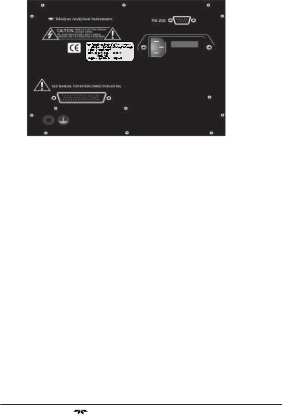
1.7Rear Panel (Equipment Interface)
All electrical inputs and outputs to the 2000A are made through rearpanel connectors. The connectors are described briefly here and in detail in chapter 3, Installation.
Teledyne Analytical Instruments |
1-5 |
1 Introduction |
Model 2000A-EU |
|
|
|
|
|
|
|
|
|
|
Figure 1-2: Model 2000A-EU Rear Panel
•Power Connection Universal AC power source.
•9-Pin RS-232 Port Serial digital concentration signal output
and control input.
•50-Pin Equipment Interface Port
• Analog Outputs 0-1 V dc concentration plus 0-1 V dc
range ID, and isolated 4-20 mA dc plus 4-20 mA dc range ID.
•Alarm Connections 2 concentration alarms and 1 system
alarm.
•Remote Valve Used in the 2000 for controlling
external solenoid valves only.
•Remote Span/Zero Digital inputs allow external control
of analyzer calibration.
•Calibration Contact To notify external equipment that
instrument is being calibrated and readings are not monitoring sample.
•Range ID Contacts Four separate, dedicated,
range-identification relay contacts (00, 01, 02, 03).
1-6 |
Teledyne Analytical Instruments |

Thermal Conductivity Analyzer |
Introduction 1 |
|
|
|
|
|
|
|
|
|
|
Note: If you require highly accurate Auto-Cal timing, use external Auto-Cal control where possible. The internal clock in the Model 2000 is accurate to 2-3 %. Accordingly, internally scheduled calibrations can vary 2-3 % per day.
1.8Gas Connections
The gas connectors are on the bottom of the Model 2000A chassis near the front panel. There are no gas control valves inside the main chassis. Electronic input/output ports are provided on the rear panel for the operation of solenoid valves under the complete control of the Model 2000 electronics. See section 3.3.
A sample system must be provided for introduction of zero and span gas, as well as sample gas, into the sample path, and for controlling the flowrates through the sample and reference paths of the analyzer. Appropriate pressure reducing regulators must be installed at all gas supply sources.
Gas Connector-and-Control Panels for specific applications are available as extra cost additions. These panels are usually designed around a standard manifold that attaches to the Model 2000 series analyzer below the front panel.
For those customers wishing to incorporate their own sample controls, the recommended system piping schematic is included among the drawings at the rear of the manual.
Teledyne Analytical Instruments |
1-7 |

1 Introduction |
Model 2000A-EU |
|
|
|
|
|
|
|
|
|
|
1-8 |
Teledyne Analytical Instruments |

Thermal Conductivity Analyzer |
Operational Theory 2 |
|
|
|
|
|
|
|
|
|
|
Operational Theory
2.1Introduction
The analyzer is composed of two subsystems:
1.Thermal Conductivity Sensor
2.Electronic Signal Processing, Display and Control.
The sensor is a thermal conductivity comparator that continuously compares the thermal conductivity of the sample gas with that of a reference gas having a known conductivity.
The electronic signal processing, display and control subsystem simplifies operation of the analyzer and accurately processes the sampled data. A microprocessor controls all signal processing, input/output, and display functions for the analyzer.
2.2Sensor Theory
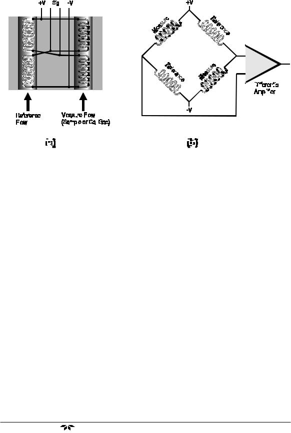
For greater clarity, Figure 2-1 presents two different illustrations, (a) and (b), of the operating principle of the thermal conductivity cell.
2.2.1 Sensor Configuration
The thermal conductivity sensor contains two chambers, one for the reference gas of known conductivity and one for the sample gas. Each chamber contains a pair of heated filaments. Depending on its thermal conductivity, each of the gases conducts a quantity of heat away from the filaments in its chamber. See Figure 2-1(a).
The resistance of the filaments depends on their temperature. These filaments are parts of the two legs of a Wheatstone bridge circuit that unbalances if the resistances of its two legs do not match. See Figure 2-1(b).
Teledyne Analytical Instruments |
2-1 |
2 Operational Theory |
|
|
|
|
|
|
|
|
|
|
|
|
|
|
|
|
|
|
|
|
|
|
|
|
|
|
|
|
|
|
|
|
|
|
|
|
|
|
|
|
|
|
|
|
|
|
Model 2000A-EU |
||||||||||||||||||||||||||||||||||||||||||||||||||||||||||||||||||||||||||||||||||||||||||||||||||||||||||
|
|
|
|
|
|
|
|
|
|
|
|
|
|
|
|
|
|
|
|
|
|
|
|
|
|
|
|
|
|
|
|
|
|
|
|
|
|
|
|
|
|
|
|
|
|
|
|
|
|
|
|
|
|
|
|
|
|
|
|
|
|
|
|
|
|
|
|
|
|
|
|
|
|
|
|
|
|
|
|
|
|
|
|
|
|
|
|
|
|
|
|
|
|
|
|
|
|
|
|
|
|
|
|
|
|
|
|
|
|
|
|
|
|
|
|
|
|
|
|
|
|
|
|
|
|
|
|
|
|
|
|
|
|
|
|
|
|
|
|
|
|
|
|
|
|
|
|
|
|
|
|
|
|
|
|
|
|
|
|
|
|
|
|
|
|
|
|
|
|
|
|
|
|
|
|
|
|
|
|
|
|
|
|
|
|
|
|
|
|
|
|
|
|
|
|
|
|
|
|
|
|
|
|
|
|
|
|
|
|
|
|
|
|
|
|
|
|
|
|
|
|
|
|
|
|
|
|
|
|
|
|
|
|
|
|
|
|
|
|
|
|
|
|
|
|
|
|
|
|
|
|
|
|
|
|
|
|
|
|
|
|
|
|
|
|
|
|
|
|
|
|
|
|
|
|
|
|
|
|
|
|
|
|
|
|
|
|
|
|
|
|
|
|
|
|
|
|
|
|
|
|
|
|
|
|
|
|
|
|
|
|
|
|
|
|
|
|
|
|
|
|
|
|
|
|
|
|
|
|
|
|
|
|
|
|
|
|
|
|
|
|
|
|
|
|
|
|
|
|
|
|
|
|
|
|
|
|
|
|
|
|
|
|
|
|
|
|
|
|
|
|
|
|
|
|
|
|
|
|
|
|
|
|
|
|
|
|
|
|
|
|
|
|
|
|
|
|
|
|
|
|
|
|
|
|
|
|
|
|
|
|
|
|
|
|
|
|
|
|
|
|
|
|
|
|
|
|
|
|
|
|
|
|
|
|
|
|
|
|
|
|
|
|
|
|
|
|
|
|
|
|
|
|
|
|
|
|
|
|
|
|
|
|
|
|
|
|
|
|
|
|
|
|
|
|
|
|
|
|
|
|
|
|
|
|
|
|
|
|
|
|
|
|
|
|
|
|
|
|
|
|
|
|
|
|
|
|
|
|
|
|
|
|
|
|
|
|
|
|
|
|
|
|
|
|
|
|
|
|
|
|
|
|
|
|
|
|
|
|
|
|
|
|
|
|
|
|
|
|
|
|
|
|
|
|
|
|
|
|
|
|
|
|
|
|
|
|
|
|
|
|
|
|
|
|
|
|
|
|
|
|
|
|
|
|
|
|
|
|
|
|
|
|
|
|
|
|
|
|
|
|
|
|
|
|
|
|
|
|
|
|
|
|
|
|
|
|
|
|
|
|
|
|
|
|
|
|
|
|
|
|
|
|
|
|
|
|
|
|
|
|
|
|
|
|
|
|
|
|
|
|
|
|
|
|
|
|
|
|
|
|
|
|
|
|
|
|
|
|
|
|
|
|
|
|
|
|
|
|
|
|
|
|
|
|
|
|
|
|
|
|
|
|
|
|
|
|
|
|
|
|
|
|
|
|
|
|
|
|
|
|
|
|
|
|
|
|
|
|
|
|
|
|
|
|
|
|
|
|
|
|
|
|
|
|
|
|
|
|
|
|
|
|
|
|
|
|
|
|
|
|
|
|
|
|
|
|
|
|
|
|
|
|
|
|
|
|
|
|
|
|
|
|
|
|
|
|
|
|
|
|
|
|
|
|
|
|
|
|
|
|
|
|
|
|
|
|
|
|
|
|
|
|
|
|
|
|
|
|
|
|
|
|
|
|
|
|
|
|
|
|
|
|
|
|
|
|
|
|
|
|
|
|
|
|
|
|
|
|
|
|
|
|
|
|
|
|
|
|
|
|
|
|
|
|
|
|
|
|
|
|
|
|
|
|
|
|
|
|
|
|
|
|
|
|
|
|
|
|
|
|
|
|
|
|
|
|
|
|
|
|
|
|
|
|
|
|
|
|
|
|
|
|
|
|
|
|
|
|
|
|
|
|
|
|
|
|
|
|
|
|
|
|
|
|
|
|
|
|
|
|
|
|
|
|
|
|
|
|
|
|
|
|
|
|
|
|
|
|
|
|
|
|
|
|
|
|
|
|
|
|
|
|
|
|
|
|
|
|
|
|
|
|
|
|
|
|
|
|
|
|
|
|
|
|
|
|
|
|
|
|
|
|
|
|
|
|
|
|
|
|
|
|
|
|
|
|
|
|
|
|
|
|
|
|
|
|
|
|
|
|
|
|
|
|
|
|
|
|
|
|
|
|
|
|
|
|
|
|
|
|
|
|
|
|
|
|
|
|
|
|
|
|
|
|
|
|
|
|
|
|
|
|
|
|
|
|
|
|
|
|
|
|
|
|
|
|
|
|
|
|
|
|
|
|
|
|
|
|
|
|
|
|
|
|
|
|
|
|
|
|
|
|
|
|
|
|
|
|
|
|
|
|
|
|
|
|
|
|
|
|
|
|
|
|
|
|
|
|
|
|
|
|
|
|
|
|
|
|
|
|
|
|
|
|
|
|
|
|
|
|
|
|
|
|
|
|
|
|
|
|
|
|
|
|
|
|
|
|
|
|
|
|
|
|
|
|
|
|
|
|
|
|
|
|
|
|
|
|
|
|
|
|
|
|
|
|
|
|
|
|
|
|
|
|
|
|
|
|
|
|
|
|
|
|
|
|
|
|
|
|
|
|
|
|
|
|
|
|
|
|
|
|
|
|
|
|
|
|
|
|
|
|
|
|
|
|
|
|
|
|
|
|
|
|
|
|
|
|
|
|
|
|
|
|
|
|
|
|
|
|
|
|
|
|
|
|
|
|
|
|
|
|
|
|
|
|
|
|
|
|
|
|
|
|
|
|
|
|
|
|
|
|
|
|
|
|
|
|
|
|
|
|
|
|
|
|
|
|
|
|
|
|
|
|
|
|
|
|
|
|
|
|
|
|
|
|
|
|
|
|
|
|
|
|
|
|
|
|
|
|
|
|
|
|
|
|
|
|
|
|
|
|
|
|
|
|
|
|
|
|
|
|
|
|
|
|
|
|
|
|
|
|
|
|
|
|
|
|
|
|
|
|
|
|
|
|
|
|
|
|
|
|
|
|
|
|
|
|
|
|
|
|
|
|
|
|
|
|
|
|
|
|
|
|
|
|
|
|
|
|
|
|
|
|
|
|
|
|
|
|
|
|
|
|
|
|
|
|
|
|
|
|
|
|
|
|
|
|
|
|
|
|
|
|
|
|
|
|
|
|
|
|
|
|
|
|
|
|
|
|
|
|
|
|
|
|
|
|
|
|
|
|
|
|
|
|
|
|
|
|
|
|
|
|
|
|
|
|
|
|
|
|
|
|
|
|
|
|
|
|
|
|
|
|
|
|
|
|
|
|
|
|
|
|
|
|
|
|
|
|
|
|
|
|
|
|
|
|
|
|
|
|
|
|
|
|
|
|
|
|
|
|
|
|
|
|
|
|
|
|
|
|
|
|
|
|
|
|
|
|
|
|
|
|
|
|
|
|
|
|
|
|
|
|
|
|
|
|
|
|
|
|
|
|
|
|
|
|
|
|
|
|
|
|
|
|
|
|
|
|
|
|
|
|
|
|
|
|
|
|
|
|
|
|
|
|
|
|
|
|
|
|
|
|
|
|
|
|
|
|
|
|
|
|
|
|
|
|
|
|
|
|
|
|
|
|
|
|
|
|
|
|
|
|
|
|
|
|
|
|
|
|
|
|
|
|
|
|
|
|
|
|
|
|
|
|
|
|
|
|
|
|
|
|
|
|
|
|
|
|
|
|
|
|
|
|
|
|
|
|
|
|
|
|
|
|
|
|
|
|
|
|
|
|
|
|
|
|
|
|
|
|
|
|
|
|
|
|
|
|
|
|
|
|
|
|
|
|
|
|
|
|
|
|
|
|
|
|
|
|
|
|
|
|
|
|
|
|
|
|
|
|
|
|
|
|
|
|
|
|
|
|
|
|
|
|
|
|
|
|
|
|
|
|
|
|
|
|
|
|
|
|
|
|
|
|
|
|
|
|
|
|
|
|
|
|
|
|
|
|
|
|
|
|
|
|
|
|
|
|
|
|
|
|
|
|
Figure 2-1: Thermal Conductivity Cell Operating Principle
If the thermal conductivities of the gases in the two chambers are different, the Wheatstone bridge circuit unbalances, causing a current to flow in its detector circuit. The amount of this current can be an indication of the amount of impurity in the sample gas, or even an indication of the type of gas, depending on the known properties of the reference and sample gases.
The temperature of the measuring cell is regulated to within 0.1 °C by a sophisticated control circuit. Temperature control is precise enough to compensate for diurnal effects in the output over the operating ranges of the analyzer. (See Specifications in the Appendix for details.)
2.2.2 Calibration
Because analysis by thermal conductivity is not an absolute measurement, calibration gases of known composition are required to fix the upper and lower parameters (“zero” and “span”) of the range, or ranges, of analysis. These gases must be used periodically, to check the accuracy of the analyzer.
During calibration, the bridge circuit is balanced, with zero gas against the reference gas, at one end of the measurement range; and it is sensitized with span gas against the reference gas at the other end of the measurement range. The resulting electrical signals are processed by the analyzer electronics to produce a standard 0-1V, or an isolated 4–20 mA dc, output signal, as described in the next section.
2-2 |
Teledyne Analytical Instruments |

Thermal Conductivity Analyzer |
Operational Theory 2 |
|
|
|
|
|
|
|
|
|
|
2.2.3 Effects of Flowrate and Gas Density
Because the flowrate of the gases in the chambers affects their cooling of the heated filaments, the flowrate in the chambers must be kept as equal, constant, and low as possible.
When setting the sample and reference flowrate, note that gases lighter than air will have an actual flowrate higher than indicated on the flowmeter, while gases heavier than air will have an actual flowrate lower than indicated. Due to the wide range of gases that are measured with the Thermal Conductivity Analyzer, the densities of the gases being handled may vary considerably.
Then, there are limited applications where the reference gas is in a sealed chamber and does not flow at all. These effects must be taken in consideration by the user when setting up an analysis.
2.2.4 Measurement Results
Thermal conductivity measurements are nonspecific by nature. This fact imposes certain limitations and requirements. If the user intends to employ the analyzer to detect a specific component in a sample stream, the sample must be composed of the component of interest and one other gas (or specific, and constant, mixture of gases) in order for the measured heat-transfer differences to be nonambiguous.
If, on the other hand, the user is primarily interested in the purity of a process stream, and does not require specific identification of the impurity, the analyzer can be used on more complex mixtures.
2.3Electronics and Signal Processing
The Model 2000 Thermal Conductivity Analyzer uses an 8031 microcontroller (Central Processing Unit—CPU) with 32 kB of RAM and 128 kB of ROM to control all signal processing, input/output, and display functions for the analyzer. System power is supplied from a universal power supply module designed to be compatible with any international power source. (See Major Internal Components in chapter 5 Maintenance for the location of the power supply and the main electronic PC boards.)
The Temperature Control board is mounted on the inner face of the rear panel, under the power input receptacle. The signal processing electronics including the microprocessor, analog to digital, and digital to analog converters are located on the Motherboard at the bottom of the case.
Teledyne Analytical Instruments |
2-3 |
2 Operational Theory |
Model 2000A-EU |
|
|
|
|
|
|
|
|
|
|
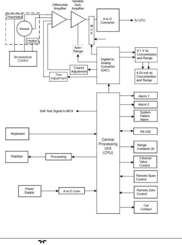
The Preamplifier board is mounted on top of the Motherboard as shown in the figure (in chapter 5). These boards are accessible after removing the back panel. Figure 2-2 is a block diagram of the Analyzer electronics.
Figure 2-2: Block Diagram of the Model 2000 Electronics
2-4 |
Teledyne Analytical Instruments |
Thermal Conductivity Analyzer |
Operational Theory 2 |
|
|
|
|
|
|
|
|
|
|
The Temperature Control Board keeps the temperature of the measuring cell regulated to within 0.1 degree C. A thermistor is used to measure the temperature, and a zero-crossing switch regulates the power in a car- tridge-type heater. The result is a sensor output signal that is temperature independent.
In the presence of dissimilar gases the sensor generates a differential voltage across its output terminals. A differential amplifier converts this signal to a unipolar signal, which is amplified in the second stage, variable gain amplifier, which provides automatic range switching under control of the CPU. The output from the variable gain amplifier is sent to an 18 bit analog to digital converter.
The digital concentration signal along with input from the control panel is processed by the CPU and passed on to the 12-bit DAC, which outputs 0-1 V dc Concentration and Range ID signals. An voltage-to- current converter provides 4-20 mA dc concentration signal and range ID outputs.
The CPU also provides appropriate control signals to the Displays, Alarms, and External Valve Controls, and accepts digital inputs for external Remote Zero and Remote Span commands. It monitors the power supply through an analog to digital converter as part of the data for the system failure alarm.
The RS-232 port provides two-way serial digital communications to and from the CPU. These, and all of the above electrical interface signals are described in detail in chapter 3 Installation.
2.4. Temperature Control
For accurate analysis the sensor of this instrument is temperature controlled to 60oC.
Teledyne Analytical Instruments |
2-5 |

2 Operational Theory |
Model 2000A-EU |
|
|
|
|
|
|
|
|
|
|
2-6 |
Teledyne Analytical Instruments |

Thermal Conductivity Analyzer |
Installation 3 |
|
|
|
|
|
|
|
Installation
Installation of the Model 2000A Analyzer includes:
1.Unpacking
2.Mounting
3.Gas connections
4.Electrical connections
5.Installing the Sensor
6.Testing the system.
3.1Unpacking the Analyzer
The analyzer is shipped ready to install and prepare for operation. Carefully unpack the analyzer and inspect it for damage. Immediately report any damage to the shipping agent.
The four gas fittings that mate with the 1/8 NPT gas ports on the Model 2000A, are not included. They must be supplied by the customer.
3.2Mounting the Analyzer
The Model 2000A is for indoor use in a general purpose area. It is NOT for hazardous environments of any type. It must be protected from:
•Direct sunlight
•Drafts of air
•Shock and vibration
•Temperatures below 30 °F (-1 °C) or above 110 °F (43 °C).
Locate the 2000A as close as possible, subject to the above conditions, to the sample point to minimize effects of sample line lag time on the analysis.
The standard model is designed for flush panel mounting. Figure 3-1 is an illustration of the 2000A standard front panel and mounting bezel. There
Teledyne Analytical Instruments |
3-1 |

3 Installation |
Model 2000A-EU |
|
|
|
|
|
|
|
are four mounting holes—one in each corner of the rigid frame. Figure 3-1a contains the hole pattern dimensions. See the outline drawing, at the back of this manual for overall dimensions.
On special order, a 19" rack-mounting panel can be provided. For rack mounting, one or two 2000A series analyzers are flush-panel mounted on the rack panel. See Figure 3-1b for dimensions of the mounting panel.
6.7"
Figure 3-1a: Front Panel of the Model 2000A
|
|
|
|
|
|
|
|
|
|
|
|
|
|
|
|
|
|
|
|
|
|
|
|
|
|
|
|
|
|
|
|
|
|
|
|
|
|
|
|
|
|
|
|
|
|
|
|
|
|
|
|
|
|
|
|
|
|
|
|
|
|
|
|
|
|
|
|
|
|
|
|
|
|
|
|
|
|
|
|
|
|
|
|
|
|
|
|
|
|
|
|
|
|
|
|
|
|
|
|
|
|
|
|
|
|
|
|
|
|
|
|
|
|
|
|
|
|
|
|
|
|
|
|
|
|
|
|
|
|
|
|
|
|
|
|
|
|
|
|
|
|
|
|
|
|
|
|
|
|
|
|
|
|
|
|
|
|
|
|
|
|
|
|
|
|
|
|
|
|
|
|
|
|
|
|
|
|
|
|
|
|
|
|
|
|
|
|
|
|
|
|
|
|
|
|
|
|
|
|
|
|
|
|
|
|
|
|
|
|
|
|
|
|
|
|
|
|
|
|
|
|
|
|
|
|
|
|
|
|
|
|
|
|
|
|
|
|
|
|
|
|
|
|
|
|
|
|
|
|
|
|
|
|
|
|
|
|
|
|
|
|
|
|
|
|
|
|
|
|
|
|
|
|
|
|
|
|
|
|
|
|
|
|
|
|
|
5.75 |
|
|
8.75 |
|
||
|
|
|
|
|
|
|
|
|
|
|
|
|
|
|
|
|
|
|
|
|
|
|
|
|
|
|
|
|
|
|
|
|
|
|
|
|
|
||||
|
|
|
|
|
|
|
|
|
|
|
|
|
|
|
|
|
|
|
|
|
|
|
|
|
|
|
|
|
|
|
|
|
|
|
|
|
|
|
|
|
|
|
|
|
|
|
|
|
|
|
|
|
|
|
|
|
|
|
|
|
|
|
|
|
|
|
|
|
|
|
|
|
|
|
|
|
|
|
|
|
|
|
|
|
|
|
|
|
|
|
|
|
|
|
|
|
|
|
|
|
|
|
|
|
|
|
|
|
|
|
|
|
|
|
|
|
|
|
|
|
|
|
|
|
|
|
|
|
|
|
|
|
|
|
|
|
|
|
|
|
|
|
|
|
|
|
|
|
|
|
|
|
|
|
|
|
|
|
|
|
|
|
|
|
|
|
|
|
|
|
|
|
|
|
|
|
|
|
|
|
|
|
|
|
|
|
|
|
|
|
|
|
|
|
|
|
|
|
|
|
|
|
|
|
|
|
|
|
|
|
|
|
|
|
|
|
|
|
|
|
|
|
|
|
|
|
|
|
|
|
|
|
|
|
|
|
|
|
|
|
|
|
|
|
|
|
|
|
|
|
|
|
|
|
|
|
|
|
|
|
|
|
|
|
|
|
|
|
|
|
|
|
|
|
|
|
|
|
|
|
|
|
|
|
|
|
|
|
|
|
|
|
|
|
|
|
|
|
|
|
|
|
|
|
|
|
|
|
|
|
|
|
|
|
|
|
|
|
|
|
|
|
|
|
|
|
|
|
|
|
|
|
|
|
|
|
|
|
|
|
|
|
|
|
|
|
|
|
|
|
|
|
|
|
|
|
|
|
|
|
|
|
|
|
|
|
|
|
|
|
|
|
|
|
|
|
|
|
|
|
|
|
|
|
|
|
|
|
|
|
|
|
|
|
|
|
|
|
|
|
|
|
|
|
|
|
|
|
|
|
|
|
|
|
|
|
|
|
|
|
|
|
|
|
|
|
|
|
|
|
|
|
|
|
|
|
|
|
|
|
|
|
|
|
|
|
|
|
|
|
|
|
|
|
|
|
|
|
|
|
|
|
|
|
|
|
|
|
|
|
|
|
|
|
|
|
|
|
|
|
|
|
|
|
|
|
|
|
|
|
|
|
|
|
|
|
|
|
|
|
|
|
|
|
|
|
|
|
|
|
|
|
|
|
|
|
|
|
|
|
|
|
|
|
|
|
|
|
|
|
|
|
|
|
|
|
|
|
|
|
|
|
|
|
|
|
|
|
|
|
|
|
|
|
|
|
|
|
|
|
|
|
|
|
|
|
|
|
|
|
|
|
|
|
|
|
|
|
|
|
|
|
|
|
|
|
|
|
|
|
|
|
|
|
|
|
|
|
|
|
|
|
|
|
|
|
|
|
|
|
|
|
|
|
|
|
|
|
|
|
|
|
|
|
|
|
|
|
|
|
|
|
|
|
|
|
|
|
|
5.75 |
8.75 |
||||
|
|
|
|
|
|
|
|
|
|
||||||
|
|
|
|
|
|
|
|
|
|
|
|
|
|
|
|
|
|
|
|
|
|
|
|
|
|
|
|
|
|
|
|
|
|
|
|
|
|
|
|
|
|
|
|
|
|
|
|
|
|
|
|
|
|
|
|
|
|
|
|
|
|
|
|
|
|
|
|
|
|
|
|
|
|
|
|
|
|
|
|
Figure 3-1b: Single and Dual 19" Rack Mounts
3-2 |
Teledyne Analytical Instruments |
Thermal Conductivity Analyzer |
Installation 3 |
|
|
|
|
|
|
|
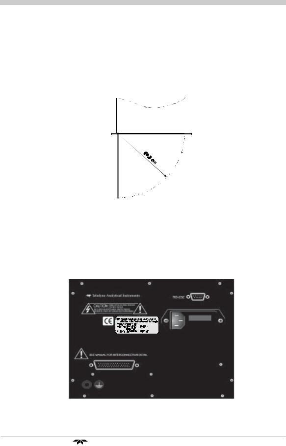
All operator controls are mounted on the control panel, which is hinged on the left edge and doubles as the door that provides access to the sensor inside the instrument. The door is spring loaded and will swing open when the button in the center of the latch (upper right corner) is pressed all the way in with a narrow gauge tool (less than 4.5 mm wide), such as a small hex wrench or screwdriver Allow clearance for the door to open in a 90-degree arc of radius 19.3 cm. See Figure 3-2.
Figure 3-2: Required Front Door Clearance
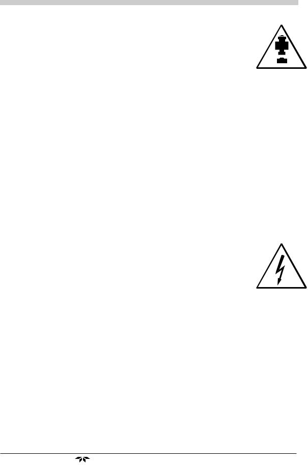
3.3Electrical Connections (Rear Panel)
Figure 3-3 shows the Model 2000A-EU rear panel. There are connectors for power, digital communications, and both digital and analog concentration output.
Figure 3-3: Rear Panel of the Model 2000A-EU
Teledyne Analytical Instruments |
3-3 |
3 Installation |
Model 2000A-EU |
|
|
|
|
|
|
|
For safe connections, no uninsulated wiring should be able to come in contact with fingers, tools or clothing during normal operation.
CAUTION: Use Shielded Cables. Also, use plugs that provide excellent EMI/RFI protection. The plug case must be connected to the cable shield, and it must be tightly fastened to the analyzer with its fastening screws. Ultimately, it is the installer who ensures that the connections provide adequate EMI/RFI shielding.
3.3.1 Primary Input Power
The power cord receptacle and fuse block are located in the same assembly. Insert the power cord into the power cord receptacle.
DANGER: POWER IS APPLIED TO THE INSTRUMENT'S CIRCUITRY AS LONG AS THE INSTRUMENT IS CONNECTED TO THE POWER SOURCE. THE STANDBY ON THE FRONT PANEL IS FOR SWITCHING POWER ON OR OFF TO THE DISPLAYS AND OUTPUTS ONLY.
The standard power supply requires a 110 V ac, 50-60 Hz power source. If you have the -N option, you will require 220 V ac, 50-60 Hz power.
3.3.2 Fuse Installation
The fuse block, at the right of the power cord receptacle, accepts US or European size fuses. A jumper replaces the fuse in whichever fuse receptacle is not used. Fuses are not installed at the factory. Be sure to install the proper fuse as part of installation. (See Fuse Replacement in chapter 5, maintenance.)
3.3.3 50-Pin Equipment Interface Connector
Figure 3-4 shows the pin layout of the Equipment Interface connector. The arrangement is shown as seen when the viewer faces the rear panel of the analyzer. The pin numbers for each input/output function are given where each function is described in the paragraphs below.
3-4 |
Teledyne Analytical Instruments |
 Loading...