


100EU
Table of contents
 Loading...
PRINT DATE: 08 April 2009
ADDENDUM TO
MODEL 100E
OPERATORS MANUAL
(P/N 04515)
FOR
MODEL 100EU
TRACE LEVEL SULFUR DIOXIDE
ANALYZER
9480 CARROLL PARK DRIVE
SAN DIEGO, CA 92121-5201
USA
Toll-free Phone: 800-324-5190
Phone: 858-657-9800
Fax: 858-657-9816
Email: Api-sales@teledyne.com
Website: http://www.teledyne-api.com/
© 2007 T-API 08 April 2009
05831 Rev C
DCN 5379


M100EU – OPERATIONS MANUAL TELEDYNE INSTRUMENTS
Addendum to M100E Manual - P/N 04515 TABLE OF CONTENTS
TABLE OF CONTENTS
1. PREFACE ..........................................................................................................................................................................3
1.1 Reference Numbering convention............................................................................................................................. 3
2. SPECIFICATIONS, APPROVALS AND WARRANTY....................................................................................................... 5
2.1 Specifications............................................................................................................................................................5
2.2 EPA Equivalency Designation................................................................................................................................... 6
2.3 CE Mark Compliance ................................................................................................................................................6
2.4 Warranty ...................................................................................................................................................................6
3. GETTING STARTED.......................................................................................................................................................... 7
3.1 Unpacking the M100EU ............................................................................................................................................7
3.2 Internal Layouts ........................................................................................................................................................7
3.3 Functional Check of the M100EU .............................................................................................................................8
3.3.1 Test Functions......................................................................................................................................................8
4. FREQENTLY ASKED QUESTIONS & GLOSSARY........................................................................................................ 11
5. OPTIONAL HARDWARE AND SOFTWARE...................................................................................................................13
6. M100EU OPERATING INSTRUCTIONS..........................................................................................................................15
6.1 Additional Test Parameters.....................................................................................................................................15
6.2 STBL MENU: Setup for the Three Stability Functions.............................................................................................15
7. CALIBRATION PROCEDURES.......................................................................................................................................17
8. EPA PROTOCOL CALIBRATION ................................................................................................................................... 19
9. INSTRUMENT MAINTENANCE....................................................................................................................................... 21
10. THEORY OF OPERATION..........................................................................................................................................23
10.1 Electronic Operation................................................................................................................................................23
10.1.1 Sensor Module ..............................................................................................................................................23
10.1.1.1 Sample Chamber......................................................................................................................................24
11. TROUBLESHOOTING & REPAIR .............................................................................................................................. 27
11.1.1 Fault Diagnosis with Warning Messages....................................................................................................... 27
11.1.2 Fault Diagnosis with Test Functions..............................................................................................................27
11.1.3 Fault Diagnosis with Sync Demod PCA LEDs............................................................................................... 29
11.2 Other Performance Problems .................................................................................................................................29
11.3 Additional Repair Procedures .................................................................................................................................29
11.3.1 UV Lamp Adjustment and/or Replacement ...................................................................................................29
11.3.1.1 Adjusting the UV Lamp (Peaking the Lamp.............................................................................................. 30
11.3.1.2 Replacing the UV Lamp............................................................................................................................32
11.3.2 Replacing the UV filter/lens............................................................................................................................. 33
11.3.3 Replacing the PMT, HVPS or TEC................................................................................................................34
11.3.4 M100EU PMT Hardware Calibration (Factory Cal)........................................................................................ 36
11.4 Technical Assistance ..............................................................................................................................................37
05944 Rev B 1
DCN 5063 PRINTED DOCUMENTS ARE UNCONTROLLED

TELEDYNE INSTRUMENTS M100EU – OPERATIONS MANUAL
TABLE OF CONTENTS
Addendum to M100E Manual - P/N 04515
LIST OF FIGURES
Figure 3-1: M100EU Internal Layout ................................................................................................................7
Figure 3-2: M100EU Test Functions ................................................................................................................9
Figure 6-1: Accessing the STBL Menu ..........................................................................................................16
Figure 10-2: M100EU Sensor Module Assembly.............................................................................................24
Figure 10-3: M100EU Sample Chamber Exploded View................................................................................25
Figure 11-1: UV Lamp Adjustment...................................................................................................................31
Figure 11-2: Disassembling the Shutter Assembly ..........................................................................................33
Figure 11-3: PMT Assembly - Exploded View..................................................................................................34
LIST OF TABLES
Table 2-1: Model 100EU Basic Unit Specifications.........................................................................................5
Table 3-1: Test Functions Defined..................................................................................................................8
Table 11-1: Test Functions - Possible Causes for Out-Of-Range Values ......................................................27
Table 11-2: Relay PCA Status LED Failure Indications..................................................................................29
USER NOTES:
2 05944 Rev B
PRINTED DOCUMENTS ARE UNCONTROLLED DCN 5063

M100EU – OPERATIONS MANUAL TELEDYNE INSTRUMENTS
Addendum to M100E Manual - P/N 04515 PREFACE
1. PREFACE
NOTE
The information contained in this addendum is pertinent to M100EU analyzers running software revision
F.0. Some or all of the information may not be applicable to later revisions of software.
The software revision your analyzer is running is displayed in the upper left-hand corner of the display
any time the instrument is in SETUP mode.
This addendum is based on the Model 100E Operators Manual (P/N 04145). In most ways the M100EU is
identical to the M100E in design and operation, therefore most of the basic set up information, operating
instructions as well as calibration, maintenance, troubleshooting and repair methods are found in that manual.
This addendum documents only those areas where the M100EU is different in design or operating method from
the M100E.
Therefore this addendum includes instructions and information regarding:
Additional Test Functions
Adjusting the PMT HV for “Factory Calibrations”
Differences in theory of operation
1.1 REFERENCE NUMBERING CONVENTION
Unless otherwise specified, chapter, section, figure and table reference numbers referred to within this text are
relative to this document.
EXAMPLE: “Figure 2-1” refers to the figure, within
References to chapters, sections, figures and tables
EXAMPLE: “Figure 6.1 of the M101E Operators Manual (P/N 04145, REV. A)”.
this document, labeled as 2-1.
in the original document will be labeled as such.
USER NOTES
05944 Rev
DCN 5063 PRINTED DOCUMENTS ARE UNCONTROLLED
B 3

TELEDYNE INSTRUMENTS M100EU – OPERATIONS MANUAL
PREFACE
Addendum to M100E Manual - P/N 04515
USER NOTES:
4 05944 Rev B
PRINTED DOCUMENTS ARE UNCONTROLLED DCN 5063

M100EU – OPERATIONS MANUAL TELEDYNE INSTRUMENTS
Addendum to M100E Manual - P/N 04515 SPECIFICATIONS, APPROVALS AND WARRANTY
2. SPECIFICATIONS, APPROVALS AND WARRANTY
2.1 SPECIFICATIONS
Table 2-1: Model 100EU Basic Unit Specifications
Min/Max Range
(Physical Analog Output)
Measurement Units ppb, ppm, µg/m3, mg/m3 (user selectable)
Zero Noise2 25 ppt RMS (50 ppt RMS with 360 nM filter installed)
Span Noise2 0.5% of reading RMS, above 5 ppb
Lower Detectable Limit3 50 ppt RMS
Zero Drift (24 hours) <200 ppt (<400 ppt with 360 nM filter installed)
Zero Drift (7 days) <200 ppt (<400 ppt with 360 nM filter installed)
Span Drift (7 Days) <0.5% FS
Linearity 1% of full scale
Precision 0.5% of reading
Temperature Coefficient < 0.1% per oC
Lag Time1 30 sec
Rise/Fall Time1 95% in <140 sec
Sample Flow Rate 650cc/min. ±10%
Temperature Range 5-40oC
Humidity Range 0 - 95% RH, non-condensing
Dimensions H x W x D 7" x 17" x 23.5" (178 mm x 432 mm x 597 mm)
Weight, Analyzer
(Basic Configuration)
AC Power Rating
Environmental Installation category (over-voltage category) II; Pollution degree 2
Analog Outputs Three (3) Outputs
Analog Output Ranges
Analog Output Resolution 1 part in 4096 of selected full-scale voltage
Status Outputs 8 Status outputs from opto-isolators
Control Inputs 6 Control Inputs, 3 defined, 3 spare
Serial I/O
Certifications
1-As defined by the USEPA; 2 – 25 samples taken, 10 sec. interval; 3 – Twice zero noise
In 1ppb increments from 50ppb to 20 000ppb, dual ranges or auto ranging
45 lbs (20.5 kg) w/internal pump
100 V, 50/60 Hz (3.25A); 115 V, 60 Hz (3.0 A);
220 – 240 V, 5
100 mV, 1 V, 5 V, 10 V, 2-20 or 4-20 mA isol
All Ranges with 5% Under/Over Range
One (1) RS-232; One (1) RS-485 (2 connecters in parallel)
Baud Ra
EN61326 (1997 w/A1: 98) Class A, FCC Part 15 Subpart B Section 15.107 Class
A, ICES-003 Class A (ANSI C63.4 19
Class A.
IEC 61010-1:90 + A1:92 + A2:95,
0/60 Hz (2.5 A)
ated current loop.
te : 300 – 115200: Optional Ethernet Interface
92) & AS/NZS 3548 (w/A1 & A2; 97)
05944 Rev
B 5
DCN 5063 PRINTED DOCUMENTS ARE UNCONTROLLED

TELEDYNE INSTRUMENTS M100EU – OPERATIONS MANUAL
SPECIFICATIONS, APPROVALS AND WARRANTY
Addendum to M100E Manual - P/N 04515
2.2 EPA EQUIVALENCY DESIGNATION
At this time the M100EU has not been certified by the EPA as an equivalent method at the time of this writing
however it is anticipated that the M100EU will qualify as Reference Method Number EQSA-0495-100 per 40
CFR Part 53 in the near future. Please see section 2.2 of the M100E manual, P/N 04515 for details.
2.3 CE MARK COMPLIANCE
See Section 2.3 of the M100E Manual - P/N 04515
2.4 WARRANTY
See Section 2.4 of the M100E Manual - P/N 04515
User Notes:
6 05944 Rev B
PRINTED DOCUMENTS ARE UNCONTROLLED DCN 5063
M100EU – OPERATIONS MANUAL TELEDYNE INSTRUMENTS
Addendum to M100E Manual - P/N 04515 GETTING STARTED
3. GETTING STARTED
3.1 UNPACKING THE M100EU
Unpack the M100EU as per the directions in Section 3.1 of the M100E Manual - P/N 04515, with the following
change. There are two redheaded shipping screws that hold down the PMT/Sensor assembly and must be
removed prior to operation. They are located along the base of the PMT housing adjacent to the chassis.
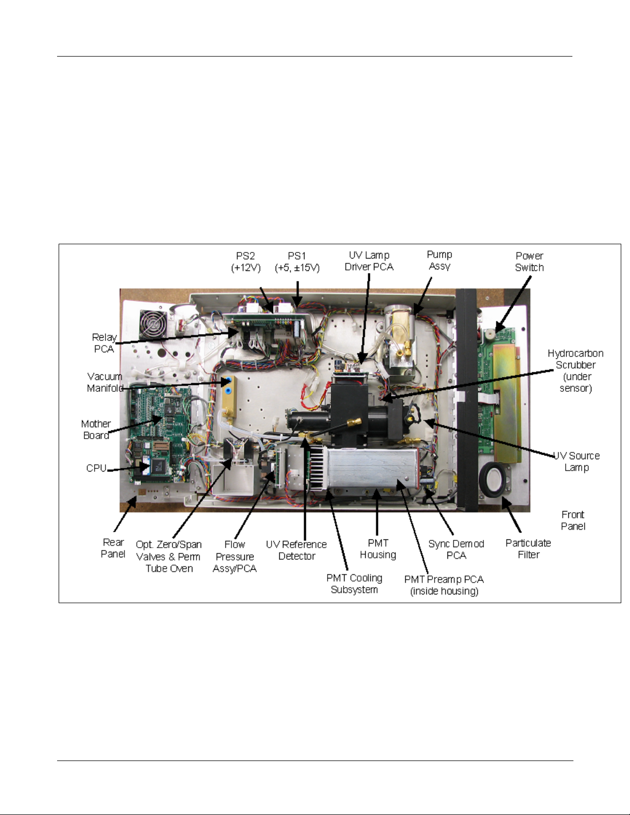
3.2 INTERNAL LAYOUTS
Figures 3-1 replaces Figure 3-9 in the M100E manual. The primary difference between the M100EU and M100E
layouts is the differences in the PMT Housing, the location of the PMT preamp PCA and the addition of a Sync
Demodulator PCA.
Figure 3-1: M100EU Internal Layout
05944 Rev
DCN 5063 PRINTED DOCUMENTS ARE UNCONTROLLED
B 7

TELEDYNE INSTRUMENTS M100EU – OPERATIONS MANUAL
GETTING STARTE
Addendum to M100E Manual - P/N 04515
D
3.3 FUNCTIONAL CHECK OF THE M100EU
To perform an initial functional check of the M100EU follow the steps contained in Section 3.2.4 of the M100E
Manual - P/N 04145, but use the Test functions described in below.
3.3.1 TEST FUNCTIONS
Table 3-1 supersedes the figure in Step 2 of Section 3.2.4 and Figure 6-2 of the M100E Manual - P/N 04145.
Table 11-1 supersedes Table 6-2. The only differences between the M100E an
the addition of STABIL2 and UV STAB.
Table 3-1: Test Functions Defined
DISPLAY PARAMETER UNITS DESCRIPTION
The Full Scale limit at which the repo
ANALOG OUTPUTS is currently set.
THIS IS NOT the Physical Range of the instrument. See Section
6.7 of M100E manual for more information.
If DUAL or AUTO Range modes have been selected, two
RANGE functio
Standard deviation of SO
are recorded every ten seconds. The calculation uses the last
25 data points.
Standard deviation of SO
Data points are recorded every 120 seconds. The calculation
uses the last 25 data points.
The current pressure of the sample
chamber, measured between the SO
The flow rate of the sample gas through the sample chamber.
Th
is value is not measured but calculated from the sample
pressure.
he output voltage of the PMT after normalization for offset and
T
temperature/pressure compensation (if activated).
Standard deviation of UV reference detector output. Data points
are recorded
25 data points.
The current output of the UV referenc
reading stored in the CPU’s memory from the last time a UV
Lamp calibration was performed.
The offset due to stray light recorded by the CPU during the last
zero-point cal
The PMT output reading recorded the la
lamp shutter was closed.
The UV reference detector output readin
the UV source lamp shutter was closed.
The sensitivity of the instrument as calculate
calibration activity.
calibration point of the analyzer.
s will appear, one for each range.
n
every ten seconds. The calculation uses the last
ibration performed.
The slope parameter is used to set the span
RANGE
STABIL
STABIL2
PRES
SAMP FL
PMT
NORM PMT
UV LAMP
UV STAB
LAMP RATIO
STR. LGT
DRK PMT
DRK LMP
SLOPE
(table continued)
RANGE
- -
RANGE1
RANGE2
STABILITY ppb
STABILITY ppb
SAMPLE PRESSURE in-Hg-A
SAMPLE FLOW
PMT Signal mV The raw output voltage of the PMT.
NORMALIZED PMT
Source UV Lamp
Intensity
Stability of UV Lamp
Intensity
UV Source lamp ratio %
Stray Light ppb
Dark PMT mV
Dark UV Source Lamp mV
measurement Slope -
SO
2
Signal
PPB,
PPM,
UGM &
MGM
cm³/min
(cc/m)
mV
mV The output voltage of the UV reference detector.
mV
d M100EU’s test functions are
rting range of the analyzer’s
Concentration readings. Data points
2
Concentration readings, per EPA.
2
gas as it enters the sample
and Auto-Zero valves.
2
e detec
tor divided by the
st time the UV source
g recorded the last time
d during the last
8 05944 Rev B
PRINTED DOCUMENTS ARE UNCONTROLLED DCN 5063
M100EU – OPERATIONS MANUAL TELEDYNE INSTRUMENTS
1
g
Addendum to M100E Manual - P/N 04515 GETTING STARTED
Table 3-1: Test Functions Defined
DISPLAY PARAMETER UNITS DESCRIPTION
lated during the last
analyzer case.
OFFSET
HVPS
RCELL TEMP
BOX TEMP
PMT TEMP
IZS TEMP
2
TEST
TIME
The overall offset of the instrument as calcu
measurement Offset -
SO
2
HVPS V The PMT high voltage power supply.
SAMPLE CHAMBER
P
TEM
BOX TEMPERATURE °C The ambient temperature of the inside of the
PMT TEMPERATURE °C The current temperature of the PMT.
1
IZS TEMPERATURE
TEST SIGNAL
CLOCK TIME
1
2
°C The current temperature of the sample chamber.
°C
mV Signal of a user-defined test function on output channel A4.
hh:mm:s
s
calibration activity. The offset parameter is used to set the zero
point of the analyzer response.
The current temperature of the internal zero/span option. Only
appears when IZS option is enabled
The current day time for iDAS records and calibration events.
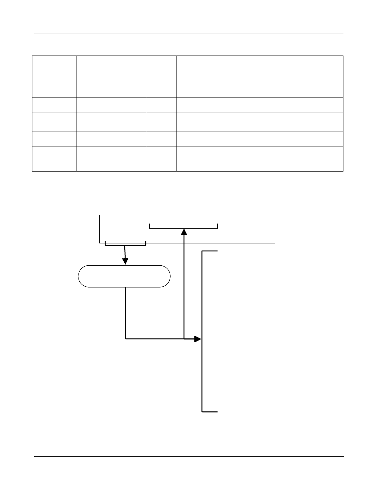
To view the TEST Functions press the following Key sequence:
SAMPLE
RANGE = 500.0 PPB
< TST TST >
CAL SETUP
Toggle <TST TST> keys to
scroll throu
Only appears if IZS option is
installed.
2
Only appears if analog output
h list of functions
A3 is actively reporting a test
function
SO2 =XXX.X
RANGE
STABIL
STABIL2
PRES
SAMP FL
PMT
NORM PMT
UV LAMP
UV STAB
LAMP RATIO
STR. LGT
DARK PMT
DARK LAMP
SLOPE
OFFSET
HVPS
RCELL TEMP
BOX TEMP
PMT TEMP
IZS TEMP
TEST
TIME
1
2
Refer to
Section
6.2.1 for
definitions
of these
test
functions.
Figure 3-2: M100EU Test Functions
05944 Rev
B 9
DCN 5063 PRINTED DOCUMENTS ARE UNCONTROLLED

TELEDYNE INSTRUMENTS M100EU – OPERATIONS MANUAL
GETTING STARTED
Addendum to M100E Manual - P/N 04515
USER NOTES:
10 05944 Rev B
PRINTED DOCUMENTS ARE UNCONTROLLED DCN 5063

M100EU – OPERATIONS MANUAL TELEDYNE INSTRUMENTS
Addendum to M100E Manual - P/N 04515 FREQENTLY ASKED QUESTIONS & GLOSSARY
4. FREQENTLY ASKED QUESTIONS & GLOSSARY
Please refer to Section 4 of the M100E manual, PN 04515 for information.
05944 Rev
DCN 5063 PRINTED DOCUMENTS ARE UNCONTROLLED
B 11

TELEDYNE INSTRUMENTS M100EU – OPERATIONS MANUAL
FREQUENT
LY ASKED QUESTIONS & GLOSSARY
Addendum to M100E Manual - P/N 04515
USER NOTES:
12 05944 Rev B
PRINTED DOCUMENTS ARE UNCONTROLLED DCN 5063

M100EU – OPERATIONS MANUAL TELEDYNE INSTRUMENTS
Addendum to M100E Manual - P/N 04515 OPTIONAL HARDWARE AND SOFTWARE
5. OPTIONAL HARDWARE AND SOFTWARE
Please refer to Section 5 of the M100E manual, PN 04515 for information.
05944 Rev
DCN 5063 PRINTED DOCUMENTS ARE UNCONTROLLED
B 13

TELEDYNE INSTRUMENTS M100EU – OPERATIONS MANUAL
OPTIONAL
HARDWARE AND SOFTWARE
Addendum to M100E Manual - P/N 04515
USER NOTES:
14 05944 Rev B
PRINTED DOCUMENTS ARE UNCONTROLLED DCN 5063

M100EU – OPERATIONS MANUAL TELEDYNE INSTRUMENTS
Addendum to M100E Manual - P/N 04515 M100EU OPERATING INSTRUCTIONS
6. M100EU OPERATING INSTRUCTIONS
NOTE
For the most part the operation instruction for the M100EU are the same as those described in Chapter 6
of the M100E Manual - P/N 04515 with the exception that there are additional test parameters and setup
procedures.
6.1 ADDITIONAL TEST PARAMETERS
Please see Section 3.3 above for details on the additional test parameters.
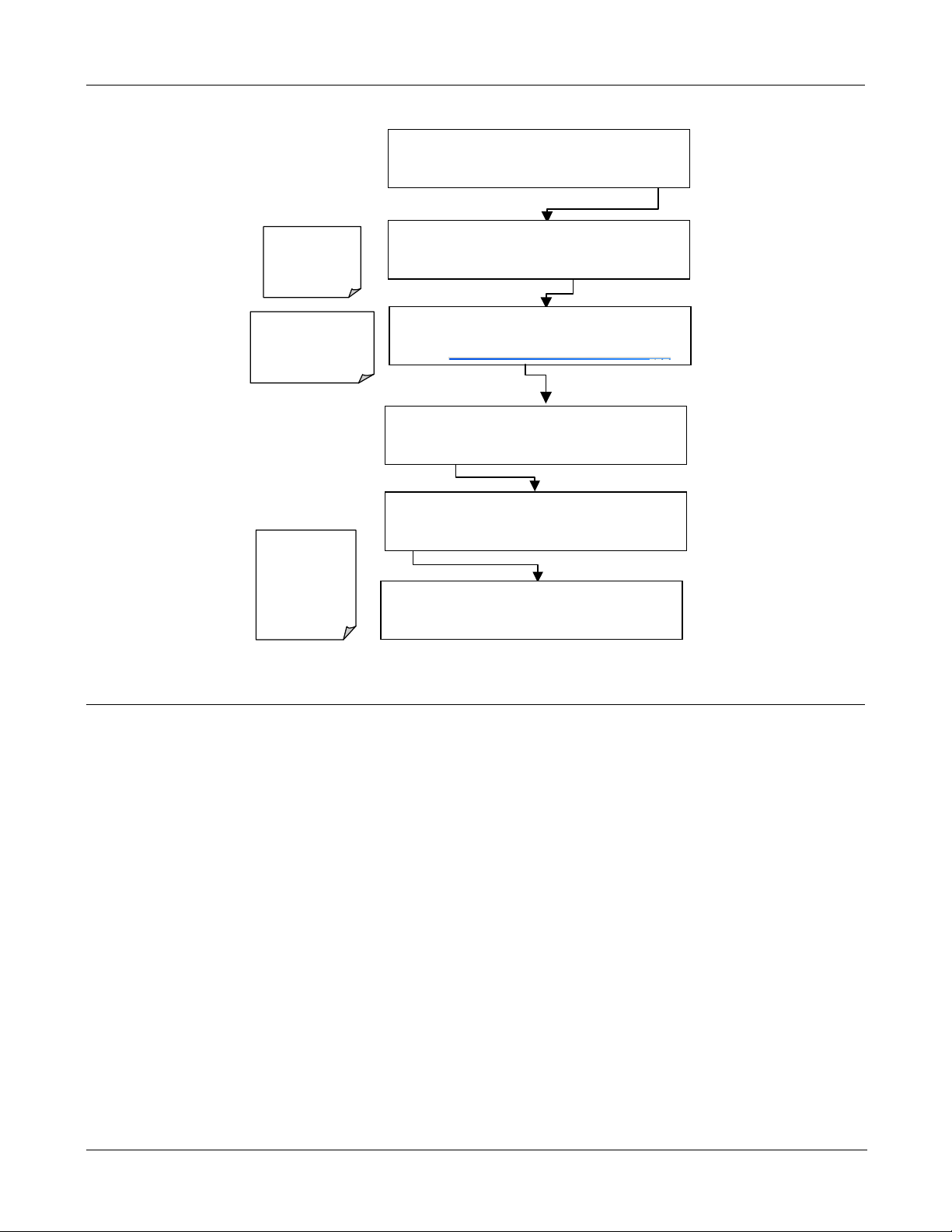
6.2 STBL MENU: SETUP FOR THE THREE STABILITY FUNCTIONS
There is an additional submenu on the Secondary Setup Menu in the M100EU’s software. The STBL menu, see
Figure 6-1 allows the user to modify the settings for the three stabili
Functions on the front panel and are available via the serial data port and that can be logged with the iDAS.
Test Function STABIL, CONC1 in the menus below, is equivalent to the standard M100E STABIL function and is
useful when conducting calibrations and other operations in which the operator has limited time to view the
display. CONC2, which is the same as the STABIL2 test function has been configured so that it calculates
stability in the same way as required by the EPA. STABIL2 is useful when comparing instruments against the
EPA standard but is very slow and difficult to use for calibration or other activities where the operator must wait
for analyzer to settle to the desired value. UVLAMP is the same as UV STAB on the front panel is a diagnostic
that can be used to understand the stability of the UV lamp.
ty calculations that are displayed as Test
05944 Rev
DCN 5063 PRINTED DOCUMENTS ARE UNCONTROLLED
B 15
TELEDYNE INSTRUMENTS M100EU – OPERATIONS MANUAL
M100EU OPERATING INSTRUCTIONS
Addendum to M100E Manual - P/N 04515
EXIT returns
to the main
SAMPLE
display
returns
EXIT
to the PRIMARY
SETUP MENU
CONC2 is
setup for
STABIL2 test
function,
UVLAMP for
UV STAB test
function
SAMPLE RANGE = 500.000 PPB SO2 =XXX.X
< TST TST > CAL SETUP
SETUP X.X
CFG DAS RNGE PASS CLK
SETUP X.X
COMM VARS
SETUP X.X
NEXT EDIT PRNT EXIT
SETUP X.X
PREV NEXT EDIT PRNT EXIT
SETUP X.X
PREV EDIT PRNT EXIT
PRIMARY SETUP MENU
EXIT
MORE
SECONDAR Y S E TU P MENU
STBL
DIAG
CONC1, 10SEC, 25 SAMPLES
CONC2, 120SEC, 25 SAMPLES
UVLAMP, 10SEC, 25 SAMPLES
User Notes:
Figure 6-1: Accessing the STBL Menu
16 05944 Rev B
PRINTED DOCUMENTS ARE UNCONTROLLED DCN 5063

M100EU – OPERATIONS MANUAL TELEDYNE INSTRUMENTS
Addendum to M100E Manual - P/N 04145 CALIBRATION PROCEDURES
7. CALIBRATION PROCEDURES
Calibration of the M100EU should be performed according to the procedures described in Chapters 7 & 8 of the
M100E Manual - P/N 04145. However, delivering span and zero gases for the lower ranges that the M100EU is
designed for can be difficult. For best results when calibrating the M100EU, wait one hour for the instrument to
stabilize when delivering zero and span gases before pressing the zero and span buttons. Attention must be
paid to the quality of the gasses, the level of contaminants in the gases as well as the history and conditioning of
the gas delivery components. Only Teflon or glass should be used for any “wetted” surfaces that the calibration
gasses contact. All delivery system components should be conditioned by running span gas for a minimum of
four hours before conducting actual span calibrations.
05944 Rev B 17
DCN 5063 PRINTED DOCUMENTS ARE UNCONTROLLED

TELEDYNE INSTRUMENTS M100EU – OPERATIONS MANUAL
CALIB
RATION PROCEDURES
Addendum to M100E Manual - P/N 04515
USER NOTES:
18 05944 Rev B
PRINTED DOCUMENTS ARE UNCONTROLLED DCN 5063

M100EU – OPERATIONS MANUAL TELEDYNE INSTRUMENTS
Addendum to M100E Manual - P/N 04145 EPA PROTOCOL CALIBRATION
8. EPA PROTOCOL CALIBRATION
The M100EU is designated as an equivalent method for measuring SO2 under certification EQSA-0495-100.
Calibration of the M100EU is done so in a manner that is consistent with EPA requirements. For calibration in
this manner please refer to section 8 of the M100E manual.
05944 Rev B 19
DCN 5063 PRINTED DOCUMENTS ARE UNCONTROLLED

TELEDYNE INSTRUMENTS M100EU – OPERATIONS MANUAL
EPA PROTOC
OL CALIBRATION
Addendum to M100E Manual - P/N 04515
USER NOTES:
20 05944 Rev B
PRINTED DOCUMENTS ARE UNCONTROLLED DCN 5063

M100EU – OPERATIONS MANUAL TELEDYNE INSTRUMENTS
Addendum to M100E Manual - P/N 04145 INSTRUMENT MAINTENANCE
9. INSTRUMENT MAINTENANCE
Instrument maintenance is almost identical to that in the M100E. The M100EU uses a 1 micron sample filter, instead of the 5
micron sample filter used in the M100E. Replacement part numbers are shown below.
Part Number Description
009690200 AKIT, TFE FLTR ELEMENT, 47MM, 1UM (100)
05920 UV Zinc LAMP, M100EU
For all other maintenance questions, please refer to section 9 in the M100E manual.
05944 Rev B 21
DCN 5063 PRINTED DOCUMENTS ARE UNCONTROLLED

TELEDYNE INSTRUMENTS M100EU – OPERATIONS MANUAL
INSTRU
MENT MAINTENANCE
Addendum to M100E Manual - P/N 04515
USER NOTES:
22 05944 Rev B
PRINTED DOCUMENTS ARE UNCONTROLLED DCN 5063
M100EU – OPERATIONS MANUAL TELEDYNE INSTRUMENTS
Addendum to M100E Manual - P/N 04145 THEORY OF OPERATION
10. THEORY OF OPERATION
The M100EU is a modified M100E. The primary differences are the way in which the PMT and UV reference
signals are acquired and processed. The M100EU has no shutter but rather employs synchronous
demodulation to capture the dark and light PMT and UV reference signals several times per second. A printed
circuit board, the Sync Demodulator, attached to the end of the PMT housing, on the sensor assembly, includes
circuitry that digitizes the PMT and UV reference signals and synchronizes the operation of the UV source with
these measurements. This method of signal processing minimizes the error that changing offsets could make in
an instrument that is designed to operate near its detection limit.
10.1 ELECTRONIC OPERATION
The following information is in addition to that contained in Section 10.2 of the M100E Manual - P/N 04145.
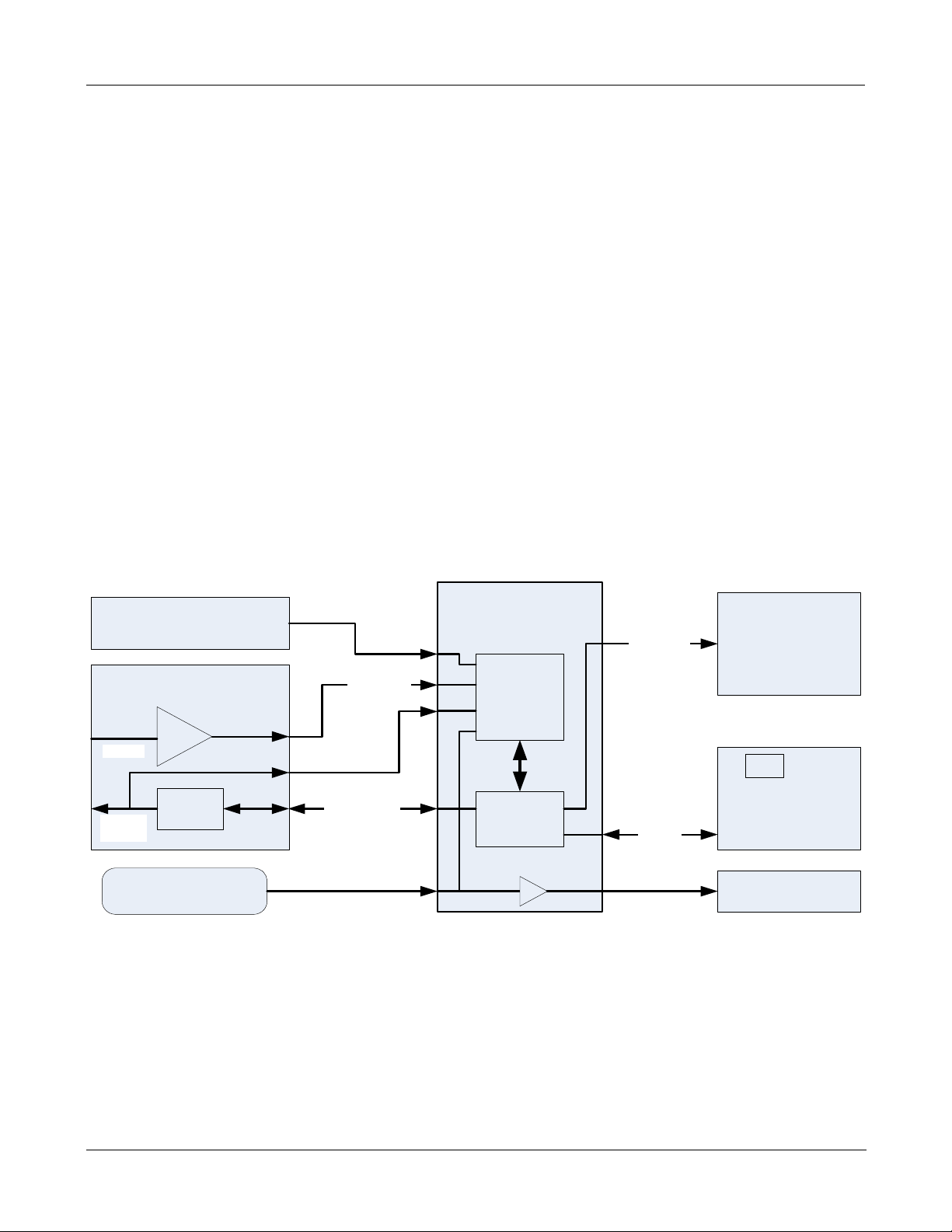
10.1.1 SENSOR MODULE
At the heart of the M100EU’s signal processing, illustrated in Figure 10-1 below, is the Synchronous
Demodulator PCA. The PCA is attached to the end of the PMT housing and serves to seal the end of the PMT
housing. The sync demodulator controls the operation of the UV Lamp driver, digitizes the analog output
signals from the PMT UV reference detector and PMT temperature sensor, controls the PMT cooler (TEC),
controls the PMT HV via a local I2C bus, and communicates with the analyzer’s CPU over the master I2C bus.
Digitized and processed data from the UV reference and PMT are passed to the analyzer’s CPU over the master
I2C bus and data for control of the PMT HV control DAC is passed from the CPU to the DAC on the PMT
preamp via the microcontroller on the Sync Demod board.
UV REF PCA
(End of Sensor Module)
PMT PREAMP PCA
(Inside PMT Housing)
PMT IN
8 bit DAC
PMT HV
Control
PMT Temp Sensor
(Inside PMT Housing)
I2C
SYNC DEMOD PCA
(End of PMT Housing)
UV REF
`
PMT Signal
PMT HV
Monitor
Local I2C Bus
A/D
Converter
Micro
Controller
Figure 10-1: Sensor Block Diagram
Lamp Sync
Master
I2C Bus
UV LAMP DRIVER
PCA
(Side of Sensor Assy)
CPU
MOTHERBOARD
(Rear Panel)
PMT Cooler
(End of PMT Housing)
05944 Rev B 23
DCN 5063 PRINTED DOCUMENTS ARE UNCONTROLLED
TELEDYNE INSTRUMENTS M100EU – OPERATIONS MANUAL
THEORY OF OPERATION
Reaction Cell
Sample Gas Inlet
Addendum to M100E Manual - P/N 04515
Lamp Shutter Housing
Sample Gas Outlet
UV LAMP
PMT PREAMP PCA
SAMPLE
CHAMBER
PMT HOUSING
Reference Detector
PMT Cooling System
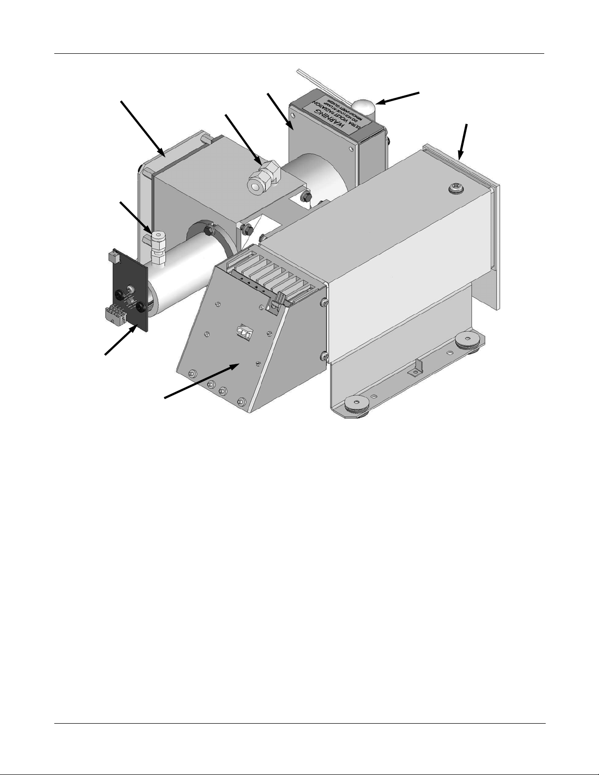
Figure 10-2: M100EU Sensor Module Assembly
These compo
nents are divided into two significant subassemblies. The sample chamber and the PMT
assembly.
Figure 10-3 shows an exploded view of the sample chamber assembly
Figure 11-3 shows an exploded view of the PMT Assembly
10.1.1.1 Sample Chamber
The main electronic components of the sample chamber are the reference detector(see Section 10.2.2 of the
M100E Manual - P/N 04145); the UV Lamp (see Section 10.2.1 of the M100E Manual - P/N 04145) and its
electronically operated shutter (see Section 9.2.1 of this addendum); and the sample chamber heating circuit,
24 05944 Rev B
PRINTED DOCUMENTS ARE UNCONTROLLED DCN 5063
Loading...