

527_Q
tekmarNet®2 Thermostat 527
Quick Setup Guide
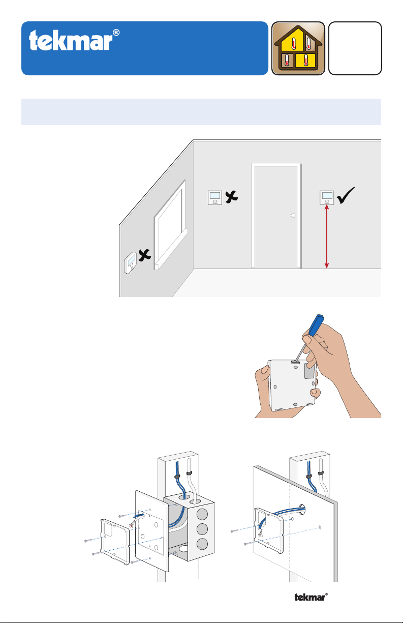
1. Location
Behind
Door
Exterior
Wall
2. Remove Mounting Base
Zoning
02/14
Replaces: 12/13
Interior
Wall
5 feet
1.5 m
3. Install Mounting Base
Adaptor
Plate 007
Thermostat
Base
Switch
Box
A Watts Water Technologies Company
1
Thermostat
Base
OR
Wall
© 2014 527_Q - 02/14
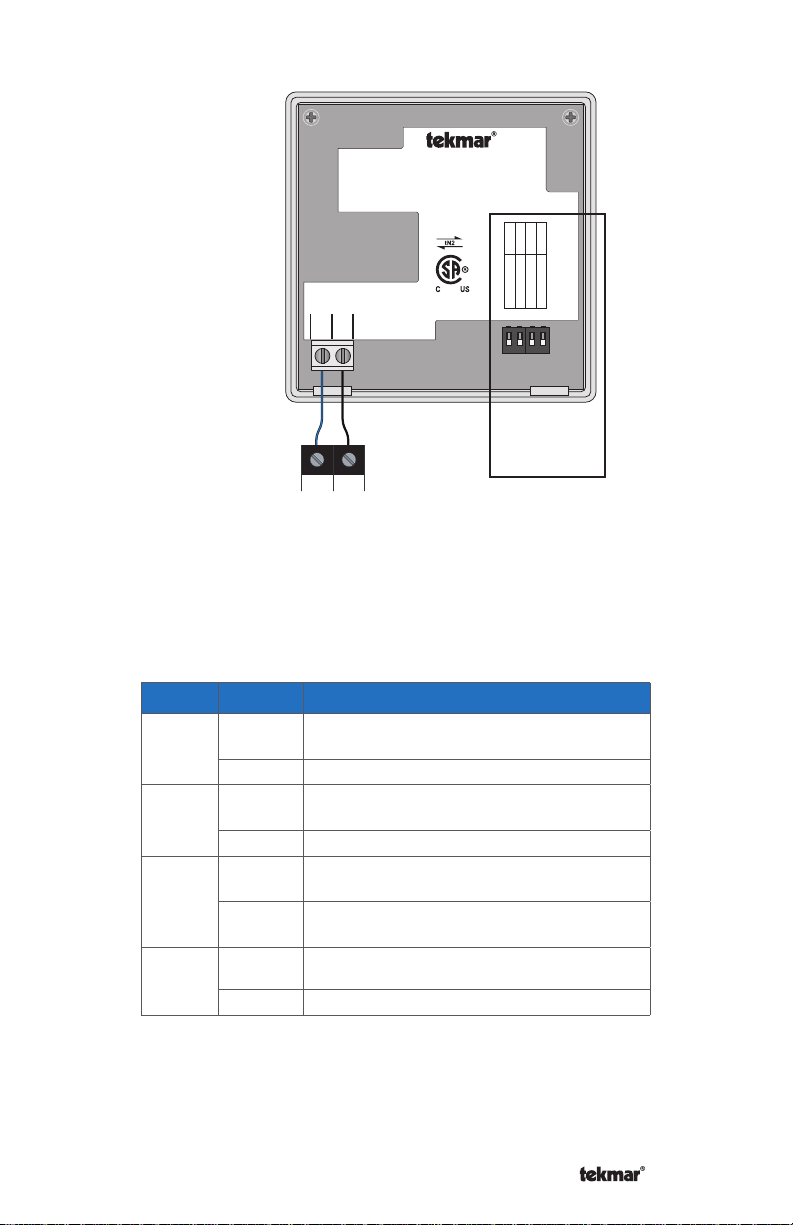
4. Wiring
tNt 527
One Stage Heat
527
1023-01
For instructions see brochure
Use at least 65°C conductors
tN21tN2
tN2 Manager, Module
or Wiring Center
tN2 tN2
5. Switch Settings
Switch
1
2
3
4
Position
ON
Action
SETBACK Allow thermostat to respond to
available schedule. Requires Timer 033.
OFF OFF No setback schedule response.
ON
SCENE Allow thermostat to respond to
scenes. Requires User Switch 479.
OFF OFF No scene response.
ON
OFF
LOCK Locked to ‘User’ access level. Set to
Lock when installation completed.
UNLOCK Unlock to access all settings. Set
to Unlock during installation.
ON Not used
OFF Not used
2
ON
Switch Settings:
12 34
Scene
Setback
Off
Off
1234
Lock
Unlock
Not used
Not used
Mmm YYYY
Lot # 12345
Meets Class B:
Canadian ICES
FCC Part 15
Switch
Setting
Location
A Watts Water Technologies Company
2
© 2014 527_Q - 02/14
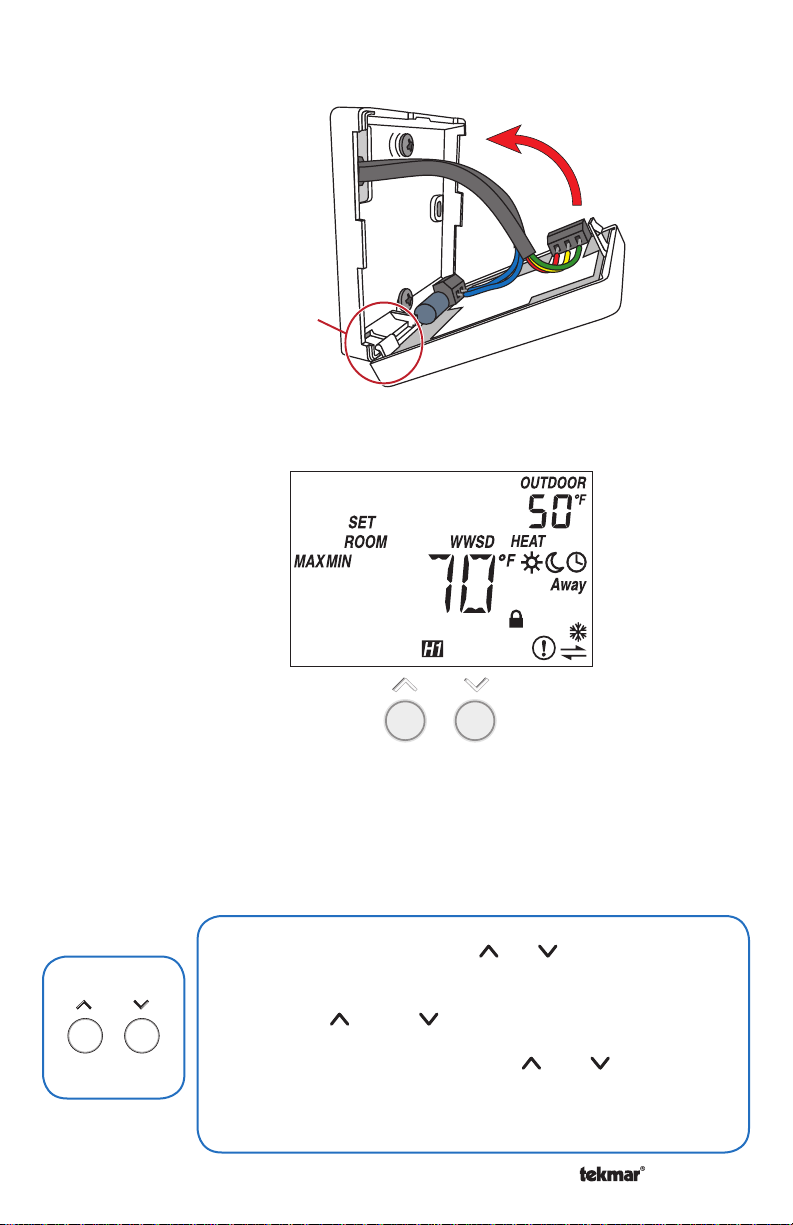
6. Close Thermostat
pivot
tab
7. User Interface
8. Critical Settings
The following settings are essential to the successful operation of the system.
Important
Access level to Installer. Return to Lock setting once installation has been completed.
Together
A Watts Water Technologies Company
Note: Set switch setting #3 and tekmarNet® system control to Unlock to change
• Press and hold down both the and buttons for 2 seconds
Press
+
to change from one step to the next.
• Release both buttons once the step has been reached.
• Press the or the button to change the setting, if
available.
• Press and hold down both the and buttons for 2
seconds to go to the next step, OR
• After 10 seconds of no button activity, the display goes
back to normal operation.
3
© 2014 527_Q - 02/14
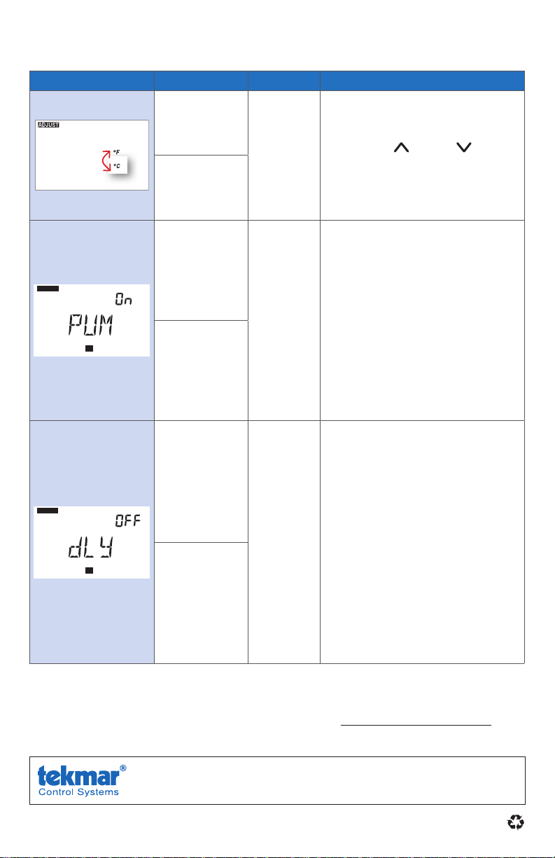
8. Critical Settings (Continued)
H1
ADJUST
H1
ADJUST
Display Range Access Description
°F or °C
Default = °F
Installer
User
Set To:
TEMPERATURE UNITS
Press the or the button
to change from °F to °C and
vice versa.
ADJUST
SUPPLY
ADJUST
SUPPLY
OFF or On
Default = On
HEAT SUPPLY PUMP
During heating, select whether
or not the system supply pump
Installer
H1
Set To:
OFF or On
Default = OFF
should turn on or be off to allow
a zone group pump per manifold.
Available when:
• A reset control is present on
the tekmarNet® system.
HEAT SUPPLY PUMP DELAY
During heating, select whether
or not the system supply pump
should be delayed by 3 minutes
Installer
H1
before coming on (for thermal
motor or wax actuator).
Available when:
• A reset control is present on
Set To:
the tekmarNet® system.
For a full list of settings and operational details, please refer to the thermostat
Installation and Operation Manual (527_D) included with compatible
tekmarNet® controls or download the brochure from www.tekmarcontrols.com
Product design, software and literature are Copyright ©2014 by tekmar Control Systems Ltd.,
All specifications are subject
to change without notice
A Watts Water Technologies Company. Head Offi ce: 5100 Silver Star Road, Vernon, B.C.
Canada V1B 3K4, 250-545-7749, Fax. 250-545-0650
4 527_Q - 02/14.
Web Site
: www.tekmarControls.com
 Loading...