

Page 1
- Data Brochure
D 508
Thermostat 508 and 509
04/12
Replaces: 05/10
Table of Contents
Display / Keypad Operation ............ pg 1
Display Symbols ............................. pg 2
General ........................................ pg 2-3
Sequence of Operation................pg 3-4
Installation - Slab Sensor 079 ......pg 4-6
Installation - Thermostats ............ pg 7-8
Wiring Examples ........................ pg 9-10
User Interface ................................pg 11
This brochure is for Thermostats 508 and 509 (with sensor). The section on the 079 slab
sensor installation is for the 509 only!
Menus .......................................pg 12-14
View Menu .............................. pg 12
Adjust Menu .......................... pg 13
Schedule Menu ...................... pg 14
Error Messages ........................... pg 14
Technical Data .............................. pg 15
Warranty ....................................... pg 16
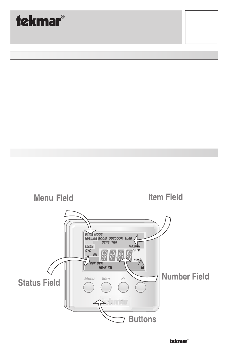
Display / Keypad Operation
The thermostat’s display has four distinct fields. These fields are the Menu field, the Item
field, the Number field and the Status field. The four buttons on the face of the thermostat are
used to navigate through the menus and items to view and / or adjust the desired settings.
Displays the
current
menu
Displays the current
status of the
thermostat's inputs,
outputs and operation
Selects Menus, Items
and adjusts settings
1 of 16 © 2012 D 508 - 04/12
Displays an abbreviated
name of the selected item
AWAY
Displays the current value
of the selected item
Page 2

Display Symbols
Warning
Displays when an error exists.
Heat One
Displays when the heat contac t
is on.
Access Level
Displays when in the user
access level.
General
CYCLES PER HOUR
The thermostat operation is based on cycles per hour. The number of cycles per hour is adjustable
through the HEAT CYC setting in the Adjust menu. During each cycle that heating is required,
the thermostat turns on the Heat relay for a calculated amount of time. This amount of time is
the “ON time”. The ON time is calculated based on the requirements of the zone. If the zone
requires more heating, the ON time is increased. If the zone requires less heating, the ON time
is reduced.
In order to prevent short cycling of the heating relay, the
thermostat ensures that the relay remains on or off for
a minimum amount of time.
An AUTO CYC setting is available for the heating cycle.
This setting allows the thermostat to determine the
best number of cycles per hour that balances both
temperature swings and equipment cycles.
Cycles Per Hour
on onon
offoff
⇐ Cycle Length ⇒
Time
off
AUXILIARY SENSOR
The thermostat has a single built-in sensor to measure air temperature at the
thermostat. In addition to the built-in sensor, the thermostat has terminals to connect
one auxiliary sensor. This sensor can be either an indoor sensor, a slab sensor, or
an outdoor sensor.
Indoor Sensor
An indoor sensor is used to measure the air temperature in the zone that the thermostat
is controlling. The temperature being read by the indoor sensor is used in the calculations
of the ON time for the relay in the thermostat. This setting is made through the Adjust
menu of the thermostat. If the built-in sensor is set to ON and the auxiliary sensor is set
to Indoor, the temperatures of the sensors are averaged and used to calculate the ON
time of the relay.
Slab Sensor
A slab sensor is used to measure the slab temperature in the zone that the thermostat
is controlling. The temperature being read by the slab sensor is used in the calculations
of the ON time for the Heat relay and allows the thermostat to operate the slab between
the slab minimum and slab maximum settings.
© 2012 D 508 - 04/12 2 of 16
Page 3
Outdoor Sensor
An outdoor sensor can be connected to the thermostat. The temperature measured by
an outdoor sensor does not affect the ON time of the relay and is only used for display
purposes.
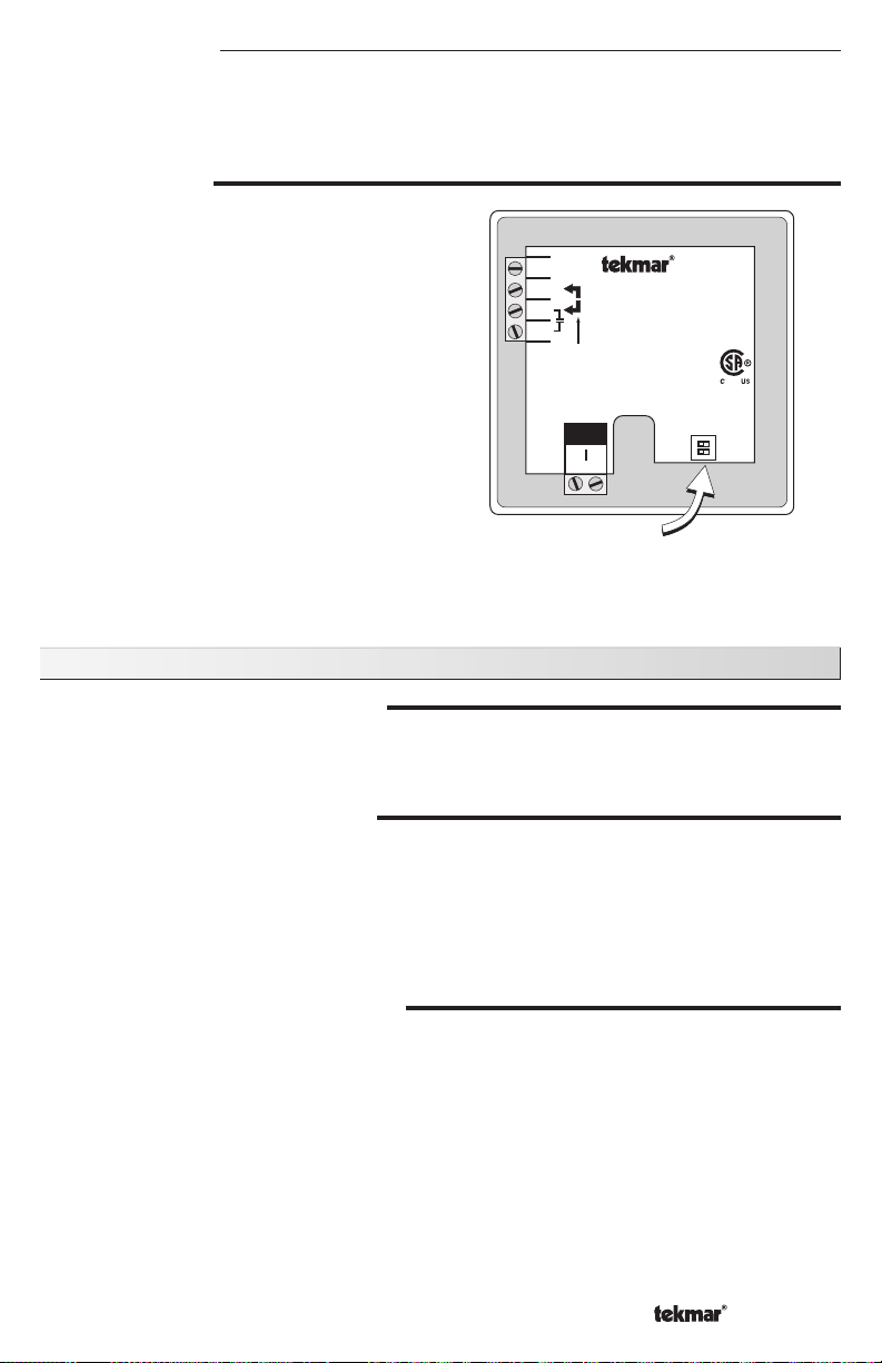
ACCESS LEVELS
The 508 thermostat has two access levels.
These access levels restrict the number of items
available in the menus of the thermostat. The
two access levels are User and Installer. This
selection is made using the DIP switch located
on the circuit board inside the thermostat.
Installer access level - allows the installer
to adjust all of the settings in the thermostat
including those required to match the thermostat
to the mechanical system and the devices
used.
24 V
4653
For 3 wires,
install jumper
R to Rh
POWER
Thermostat 508
One Stage Heat
Power:
Relay:
NO
2
1
Sensor
24 V ±10% 50/60 Hz 1.5 VA.
24 V (ac) 2 A Class 2
RhRCW
Made in
Canada
Meets Class B:
Canadian ICES
FCC Part 15
Installer
Not used
Access level
1
2
ON
508
944-02
Apr 2010
Lot 1234
User
User access level - allows the end user
to adjust the temperatures used by the
thermostat.
Dip Switch
Set to User access level once installation and settings have been completed.
Note: DIP switch 2 is not used.
Sequence of Operation
AIR SENSOR(S) ONLY OPERATION
When operating with only an air sensor, the ON time for the Heat relay is calculated to
satisfy the requirements of the air sensor.
SLAB SENSOR ONLY OPERATION
When operating with only a slab sensor, the ON time for the Heat relay is calculated to
satisfy the requirements of the slab sensor. The thermostat operates to maintain the slab
at the minimum slab temperature setting.
NOTE: Operating with only a slab sensor can lead to either overheating or underheating
of the space.
AIR AND SLAB SENSOR OPERATION
When operating with both air and slab sensors, the thermostat calculates an ON time for the
Heat relay to satisfy the slab sensor’s requirements and an ON time to satisfy the air sensor’s
requirements. The Heat relay operates for the longer of these two ON times.
During light heating loads, overheating can occur due to the minimum slab temperature
requirements.
During heavy heating loads, the maximum slab temperature setting limits the ON time of
the Heat relay. In this situation, underheating can occur.
3 of 16 © 2012 D 508 - 04/12
Page 4
MODE
•
•
Heat In the heat mode, the Heat relay is operated to satisfy the temperature
requirement of the zone.
Off In the OFF mode, the Heat relay is not operated.
NOTE: If an air or slab sensor is active in the OFF mode, a freeze protection is enabled
that allows the Heat relay to be operated to keep the zone above 35°F (2°C).
GETTING READY
Check the contents of this package. If any of the contents are missing or damaged, please
contact your wholesaler or tekmar sales representative for assistance.
Type 508 Includes:
Type 509 Includes:
• One Thermostat 508 • Data Brochure D 508 • • User Brochure U 508
• One Thermostat 508 • One 079 Slab Sensor • • Data Brochure D 508
User Brochure U 508
SLAB SENSOR 079
The tekmar Slab Sensor 079 has a stainless steel sleeve which is designed for use in
concrete, thin-set or grout. The 079 is supplied with 10’ (3 m) of 2 conductor zipcord.
Installation - Slab Sensor 079
STEP ONE
INSTALLING THE SENSOR
New Installations
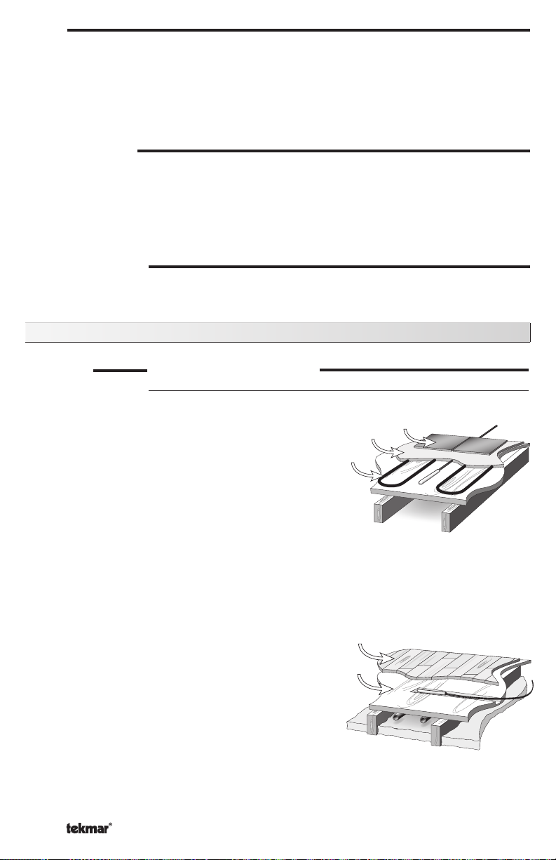
Thin-Set or Thin-Pour Applications
If the floor covering is to be installed over either
a thin-set or thin-pour material of sufficient
depth, the 079 slab sensor can be placed
Electric
Cables
Thin-set
Tiles
directly into either the thin-set material or the
thin-pour material and covered over. Ensure
that the sensor is located in such a position that
the attached wire is able to reach to a suitable
junction location. Splices within the thin-set or
thin-pour should be avoided to ensure trouble free operation. The sensor should be located
mid way between the heating elements to ensure a proper temperature reading.
Thin Floor Coverings (less than 3/8” (10 mm))
If a thin floor covering is to be installed directly
to the subfloor, a groove 1/8” (4 mm) wide by
Hardwood
1/16” (2 mm) deep can be cut into the surface of
the subfloor to accommodate the wire for the
Subfloor
sensor. Ensure that the sensor is located in
such a position that the attached wire is able
to reach to a suitable junction location. Splices
under the floor covering should be avoided to
ensure trouble free operation. A groove 3/16”
(5 mm) wide by 3/16” (5 mm) deep by 1-3/4”
(45 mm) long should be cut to accommodate the sensor. The sensor should be located
mid way between the heating elements to ensure a proper temperature reading.
© 2012 D 508 - 04/12 4 of 16
Page 5
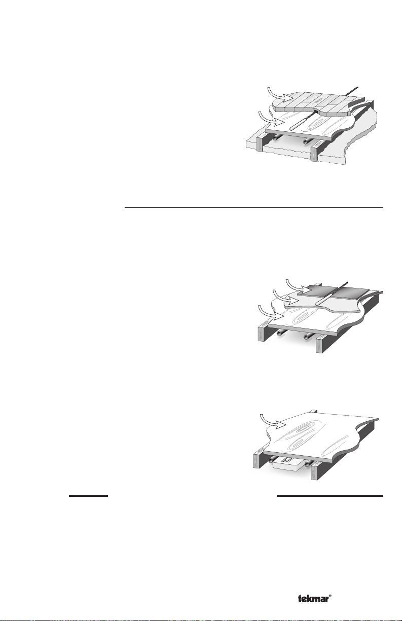
Thick Floor Coverings (greater than 3/8” (10 mm))
If a thick floor covering is to be installed directly to the subfloor, a groove 1/8” (4 mm) wide
by 1/16” (2 mm) deep can be cut into the back of the flooring material to accommodate
the wire for the sensor. Ensure that the sensor is located in such a position that the
attached wire is able to reach to a suitable junction location.
Splices under the floor covering should be
avoided to ensure trouble free operation. A
groove 3/16” (5 mm) wide by 3/16” (5 mm)
Hardwood
Subfloor
deep by 1-3/4” (45 mm) long should be cut to
accommodate the sensor. The sensor should be
located mid way between the heating elements
to ensure a proper temperature reading.
NOTE: If it is not practical to cut a groove in the surface covering, follow the installation
method used for thin floor coverings.
Retrofit Installations
Tile Floor Coverings
If a Slab Sensor 079 is to be installed into an existing tile floor with sufficiently large grout
lines, the sensor and wire can be installed in one of the grout lines between the tiles.
Select a low traffic area of the floor that is mid way between the heating elements for
the sensor location. Ensure that the sensor is
located in such a position that the attached wire
is able to reach to a suitable junction location.
Splices within the grout should be avoided to
Subfloor
Tiles
Thin-set
ensure trouble free operation. Remove the
appropriate grout line and place the sensor and
wire in the floor. Re-grout the area.
Installing the Sensor to the Bottom of a Subfloor
If the sensor is to be installed to the bottom of a subfloor, cut a piece of 1” (25 mm)
thick rigid insulation into a 6” (150 mm) by 6” (150 mm) square. A groove 3/16” (5
mm) wide by 3/16” (5 mm) deep by 1-3/4”
(45 mm) long should be cut into the insulation
Subfloor
to accommodate the sensor. Place the sensor
in the groove and sandwich the sensor between
the insulation and the subfloor. Use a suitable
fastening method to affix the insulation to the
subfloor.
STEP TWO
WIRING AND TESTING THE SENSOR
Caution: Do not run sensor wires parallel to telephone or power cables. If the sensor wires
are located in an area with strong sources of electromagnetic interference, shielded cable
or twisted pair should be used or the wires can be run in a grounded metal conduit.
The Slab Sensor 079 is supplied with 10’ (3 m) of cable. If a longer length is required, 24
AWG or larger wire can be spliced onto the two wires from the sensor. The splices should
be properly soldered and protected in an accessible junction box. Follow the sensor testing
instructions given in this brochure and then connect the wires to the control.
5 of 16 © 2012 D 508 - 04/12
Page 6

Sensor Testing Instructions
°F °C
°F °C
°F °C
0 -18 85,362 70 21 11,883 140 60 2,490 210 99 703
5 -15 72,918 75 24 10,501 145 63 2,255 215 102 648
°F °C
-50 -46 490,813 20 -7 46,218 90 32 7,334 160 71 1,689
-45 -43 405,710 25 -4 39,913 95 35 6,532 165 74 1,538
-40 -40 336,606 30 -1 34,558 100 38 5,828 170 77 1,403
-35 -37 280,279 35 2 29,996 105 41 5,210 175 79 1,281
-30 -34 234,196 40 4 26,099 110 43 4,665 180 82 1,172
-25 -32 196,358 45 7 22,763 115 46 4,184 185 85 1,073
Temperature Resistance Temperature Resistance Temperature Resistance Temperature Resistance
© 2012 D 508 - 04/12 6 of 16
-20 -29 165,180 50 10 19,900 120 49 3,760 190 88 983
-15 -26 139,402 55 13 17,436 125 52 3,383 195 91 903
-10 -23 118,018 60 16 15,311 130 54 3,050 200 93 829
-5 -21 100,221 65 18 13,474 135 57 2,754 205 96 763
10 -12 62,465 80 27 9,299 150 66 2,045 220 104 598
15 -9 53,658 85 29 8,250 155 68 1,857 225 107 553
to this, the actual temperature must be measured with either a good quality digital thermometer, or if a thermometer is not available, a
A good quality test meter capable of measuring up to 5,000 k (1 k = 1000) is required to measure the sensor resistance. In addition
second sensor can be placed alongside the one to be tested and the readings compared.
First measure the temperature using the thermometer and then measure the resistance of the sensor at the control. The wires from the
sensor must not be connected to the control while the test is performed. Using the chart on the following page, estimate the temperature
measured by the sensor. The sensor and thermometer readings should be close. If the test meter reads a very high resistance, there
may be a broken wire, a poor wiring connection or a defective sensor. If the resistance is very low, the wiring may be shorted, there may
be moisture in the sensor or the sensor may be defective. To test for a defective sensor, measure the resistance directly at the sensor
location.
Do not apply voltage to a sensor at any time as damage to the sensor may result.
Page 7

Installation - Thermostat
•
•
•
•
STEP ONE
REMOVING THE FRONT COVER
Place a screwdriver or similar object into the small slot located in the top of the thermostat.
Push the screwdriver against the plastic tab and pull the top of the front cover so that it pivots
around the bottom edge of the base.
Push tab
1
Remove cover
2
Item
Menu
STEP TWO
MOUNTING THE BASE
The thermostat should be installed on an interior wall of the desired zone approximately 5’ (1.5
m) above the floor. Do not mount the thermostat in a location that may be affected by localized
heat sources or cold drafts. It may be necessary to install a draft barrier behind the thermostat to
prevent air from blowing through the wiring hole and affecting the thermostat’s built-in sensor.
Mount the base directly to the wall using two #6
1” screws. The screws are inserted through the
mounting holes and must be securely fastened
to the wall. If possible, at least one of the screws
should enter a wall stud or similar surface. If the
thermostat is to be mounted to a 2” x 4” electrical
box, order an Adaptor Plate 007. This plate mounts
to the electrical box and the thermostat mounts to
the plate. Ensure that the electrical box does not
#6 1” screws
provide cold air to the thermostat.
NOTE: If the 508 is to be used for remote sensing (i.e. The built-in air sensor is disabled
and an indoor sensor is being used.) Mount the thermostat in the desired location in an
appropriate manner.
STEP THREE
18 AWG or similar wire is recommended for all 24 V (ac) wiring.
All wires are to be stripped to 1/4” (6 mm) to ensure proper connection to the control.
Run wires from the 24 V (ac) power to the thermostat. Use a clean power source to
ROUGH IN WIRING
ensure proper installation.
Run wires from the heating device to the thermostat.
7 of 16 © 2012 D 508 - 04/12
Page 8

STEP FOUR
WIRING THE THERMOSTAT
(Refer to the examples on the following page.)
24 V (ac) Power
Connect the 24 V (ac) power to the R and C terminals of the thermostat. This connection
provides power to the microprocessor and display of the thermostat.
Auxiliary Sensor
Either an indoor, slab, or outdoor sensor may be connected to the auxiliary sensor input.
Connect the two wires from the auxiliary sensor to the Sensor terminals.
Heat Relay (Rh – W)
The Heat Relay Rh – W terminals are an isolated output. There is no power available
on these terminals from the thermostat. These terminals are to be used as a switch for
a 24 V (ac) circuit. This circuit can operate a low current 24 V (ac) device directly or an
external relay to enable a line voltage or high current device.
STEP FIVE
INSTALLING THE FRONT COVER
Align the hinges on the bottom of the front cover with the bottom of the thermostat mounting
base. Pivot the front cover around the bottom hinges and push the top against the mounting
base until it snaps firmly in place.
2
Pivot front
cover around
bottom hinges
Item
Menu
Align hinges
1
on bottom
of front cover
© 2012 D 508 - 04/12 8 of 16
Page 9

Wiring Examples
115 V (ac)
24 V (ac)
Sensor Wires
115 V (ac)
24 V (ac)
Sensor Wires
115 V (ac)
N
L
C
Zone 2
WtN4CtN4C
Zon
e 1
Zone 1 Expansion
Zon
e 2
Zon
e 3
Zon
e 4
End Switch
X X
Input Power
RR
tN4 Wiring Center 316
C
Four Zone Pumps
24 V (ac)
Class 2
Transformer
Wiring to a tekmar Wiring Center 315 or 316
WtN4 R C
WtN4 R C
Zone 3
Power
End Switch
Input Power: 24 V (ac) ±10% 60 Hz
11 VA Class 2
End Switch: 24 V (ac) 2 A
Pump Relays: 115 V (ac) 5 A
Zone Power: 115 V (ac) 12 A
Use at least 167°F (75°C) conductors
Red
24 V (ac)
WtN4 R
Zone 4
Made in Canada
tektra 1031-01
Black
Class 2
Transformer
H8002A
N
115 V (ac)
L
Wiring to 24 V (ac) Zone Valve
4653
RhRCW
For 3 wires,
install jumper
R to Rh
Zone
M
Valve
24 V
4653
Thermostat 508
RhRCW
One Stage Heat
Power:
Relay:
For 3 wires,
install jumper
R to Rh
NO
POWER
2
1
Sensor
Auxiliary Sensor
24 V
Thermostat 508
One Stage Heat
Power:
24 V ±10% 50/60 Hz 1.5 VA.
Relay:
24 V (ac) 2 A Class 2
NO
POWER
2
1
Sensor
24 V ±10% 50/60 Hz 1.5 VA.
24 V (ac) 2 A Class 2
Made in
Canada
Meets Class B:
Apr 2010
Canadian ICES
FCC Part 15
Lot 1234
Access level
1
ON
User
Installer
2
Not used
508
944-02
Made in
Canada
Meets Class B:
Apr 2010
Canadian ICES
FCC Part 15
Lot 1234
Access level
1
ON
User
Installer
2
Not used
508
944-02
Auxiliary Sensor
9 of 16 © 2012 D 508 - 04/12
Page 10

115 V (ac)
24 V (ac)
Sensor Wires
Unpowered
Relay
N
115 V (ac)
L
3
4
5
6
Zone Pump
Transformer
2
1
8
7
Class 2
Wiring to Unpowered 24 V (ac) Relay
24 V
4653
RhRCW
For 3 wires,
install jumper
R to Rh
NO
POWER
1
Sensor
24 V (ac)
Auxiliary Sensor
Thermostat 508
One Stage Heat
Power:
24 V ±10% 50/60 Hz 1.5 VA.
Relay:
24 V (ac) 2 A Class 2
Made in
Canada
Meets Class B:
Canadian ICES
FCC Part 15
Installer
Not used
2
Access level
1
2
ON
508
944-02
Apr 2010
Lot 1234
User
115 V (ac)
24 V (ac)
Sensor Wires
24 V
Com
Class 2
Transformer
Switching Relay
Wiring to Switching Relay
W
W
R
(T)(T)
Zone 1 Zone 2 Zone 3
HNX X HNHN NH
R
W
R
(T)(T)
(T)(T)
Zone Pump
N
115 V (ac)
L
© 2012 D 508 - 04/12 10 of 16
24 V
4653
For 3 wires,
install jumper
R to Rh
POWER
Thermostat 508
One Stage Heat
Power:
Relay:
NO
2
1
Sensor
24 V ±10% 50/60 Hz 1.5 VA.
24 V (ac) 2 A Class 2
RhRCW
Auxiliary Sensor
Made in
Canada
Meets Class B:
Canadian ICES
FCC Part 15
Installer
Not used
Access level
1
2
ON
508
944-02
Apr 2010
Lot 1234
User
Page 11

User Interface
MENU BUTTON
The menus display in the Menu Field at the left of the LCD.
Three menus are available:
• View
• Adjust
• Schd (Schedule)
To select a menu, press and release the Menu button.
ITEM BUTTON
In each menu, a group of items can be selected. The abbreviated name of the selected
item displays in the Item field of the LCD display.
• To view the next available item, press and release the Item button.
• To view the previous item, hold down the Item button and press and release the Up
button.
ADJUSTING A SETTING
To adjust a setting:
1. Use the Menu button to select the appropriate menu.
2. Use the Item button to find the desired setting.
3. Use the Up or Down button to adjust the setting.
11 of 16 © 2012 D 508 - 04/12
Page 12

View Menu
ROOM TARGET
The current desired air temperature for the space. This item is
only available in the Installer access level.(Must have an active
air sensor.)
ROOM
The current air temperature for the space. (Must have at least one
active air sensor. This is the average of all active air sensors.
OUTDOOR
The current temperature at the outdoor sensor.
(SENS must be set to OUT.)
SLAB
The current slab temperature. (Must have an active slab sensor.)
The MIN segment is displayed when running at Slab Minimum.
© 2012 D 508 - 04/12 12 of 16
Page 13

Adjust Menu
MODE
Current mode of operation of the thermostat.
OFF, HEAT
ROOM HEAT
Desired temperature for heating. (Must have an active air sensor
and be set to HEAT.)
35 to 100°F (1.5 to 38.0°C)
SLAB MINIMUM
Minimum slab temperature. (Must have an active slab sensor.)
OFF, 34 to 122°F (OFF, 1.0 to 50.0°C)
SLAB MAXIMUM
Maximum slab temperature. This item is only available in the
Installer access level. (Must have an active slab sensor.)
34 to 122°F, OFF (1.0 to 50.0°C, OFF)
SENSOR
Selects the type of auxiliary sensor present. This item is only
available in the Installer access level.
OFF, Indr, SLAB, OUT
ROOM SENSOR
Selects whether the built-in sensor is functional or not. This item
is only available in the Installer access level.
OFF, On
HEATING CYCLE
Determines the number of cycles per hour for the heating equipment.
This item is only available in the Installer access level.
Au, 2 to 12
UNITS
The units of temperature used to display the items.
°F, °C
13 of 16 © 2012 D 508 - 04/12
Page 14

Schedule Menu
Error Messages
AWAY OVERR IDE
Selects an automatic setback temperature of 62°F (16.5°C) without
altering the normal room temperature setting (Slab minimum is
ignored). Select between None & Away.
E01
The thermostat was unable to read a piece of information stored
in its memory. The thermostat was required to load the factory
settings. The thermostat will stop operation until all settings are
checked. To clear this error, select the Installer access level and
check all of the settings in the Adjust menu.
E02
There are no active sensors selected on the thermostat. Either the
internal sensor must be turned on or the auxiliary sensor must be
set to either INDR or SLAB. After the fault is corrected, press any
button to clear the error message.
ROOM SHORT
The thermostat’s internal air sensor is short circuit. This cannot
be repaired in the field. The thermostat should be replaced or
returned for repair.
ROOM OPEN
The thermostat’s internal air sensor is open circuit. This cannot be
repaired in the field. Either turn off the internal sensor and use an
auxiliary sensor set to INDR or replace the thermostat. After the
fault is corrected, press any button to clear the error message.
SENSOR SHORT
The auxiliary sensor is short circuit. Locate and repair the problem
as described in the appropriate sensor brochure. After the fault is
corrected, press any button to clear the error message.
SENSOR OPEN
The auxiliary sensor is open circuit. Locate and repair the problem
as described in the appropriate sensor brochure. After the fault is
corrected, press any button to clear the error message.
© 2012 D 508 - 04/12 14 of 16
Page 15

Technical Data
Thermostat 508 One Stage Heat
Literature D508, U508, C508
Control Microprocessor control. This is not a safety (limit) control
Packaged weight 0.5 lb. (230 g)
Dimensions 2-7/8” H x 2-7/8” W x 13/16” D (73 x 73 x 21 mm)
Enclosure White PVC plastic, NEMA type 1
Approvals
Ambient conditions
Power supply 24 V (ac) ±10%, 50/60 Hz, 1.5 VA
Relay 24 V (ac) 2 A max, Class 2
Sensors NTC thermistor, 10 kΩ @ 77°F (25°C ±0.2°C) ß=3892
–Included 508 (None) 509 (079)
–Optional tekmar type #: 070, 072, 073, 076, 077, 079, 084
Warranty Limited 3 Year (See D508 for full warranty)
CSA C US, meets class B: ICES & FCC Part 15
Indoor use only, -22 to 131°F (-30 to 55°C), RH ≤90% Noncondensing
Slab Sensor 079
Literature D079, C079
Packaged weight 0.1 lb. (50 g)
Dimensions 3/16” OD x 1-1/2” (5 OD x 38 mm)
Sensor Material
Approvals
Operating range -58 to 140°F (-50 to 60°C)
Sensor NTC thermistor, 10 kΩ @ 77°F (25°C ±0.2°C) ß=3892
Warranty Limited 3 Year (See D079 for full warranty)
316 stainless steel, 10’ (3 m) 24 AWG, 300 volt PVC insulated
Zipcord
CSA C US
Notes
15 of 16 © 2012 D 508 - 04/12
Page 16

Limited Warranty and Product Return Procedure
Limited Warranty The li ability of t ekm ar unde r this wa rra nty is limited. The Purchaser, by t aki ng rece ipt of
any tekmar product (“Product”), acknowledges the terms of the Limited Warranty in effect at the time of
such Product sale and acknowl edges that it has read and und erstands same.
The tekmar Limited Warranty to the Purchaser on the Products sold hereunder is a manufacturer’s passthrough warranty which the Purchaser is authorized to pass through to its customers. Under the Limited
Warranty, each tekmar Product is warranted against defects in workmanship and materials if the Product
is installed and used in compliance with tekmar’s instructions, ordinary wear and tear excepted. The passthrough warranty period is for a period of twenty-four (24) months from the production date if the Product is
not installed during that period, or twelve (12) months from the documented date of installation if installed
within twenty-four (24) months from the production date.
The liability of tekmar under the Limited Warranty shall be limited to, at tekmar’s sole discretion: the cost of par ts
and labor provided by tekmar to repair defects in materials and / or workmanship of the defective product; or to
the exchange of the defective product for a warrant y replacement product; or to the granting of credit limited to the
original cost of the defective product, and such repair, exchange or credit shall be the sole remedy available from
tekmar, and, without limiting the foregoing in any way, tekmar is not responsible, in contract, tort or stric t product
liability, for any other losses, costs, expenses, inconveniences, or damages, whether direct, indirect, special, secondar y, incidental or c onsequential, arising from ownership or use of the product, or from defects in workmanship
or materials, including any liability for fundamental breach of contract.
The pass-through Limited Warranty applies only to those defective Products returned to tekmar during the warranty period. This Limited Warranty does not cover the cost of the par ts or labor to remove or transport the defective Product, or to reinstall the repaired or replacement Product, all such c osts and expenses being subject to
Purchaser’s agreement and warrant y with its customers.
Any representations or warranties about the Products made by Purchaser to its customers which are different from
or in excess of the tekmar Limited Warranty are the Purchaser’s sole responsibility and obligation. Purchaser shall
indemnify and hold tekmar harmless from and against any and all claims, liabilities and damages of any kind or
nature which arise out of or are related to any such representations or warranties by Purchaser to its customers.
The pass-through Limited Warranty does not apply if the returned Product has been damaged by negligence by
persons other than tekmar, accident, fire, Act of God, abuse or misuse; or has been damaged by modifications,
alterations or at tachments made subsequent to purchase which have not been authorized by tek mar; or if the Product was not installed in compliance with tekmar’s instructions and / or the local codes and ordinances; or if due to
defective installation of the Product; or if the Product was not used in c ompliance with tekmar’s instructions.
THIS WARRANTY IS IN LIEU OF ALL OTHER WARRANTIES, EXPRESS OR IMPLIED, WHICH THE GOVERNING
LAW ALLOWS PARTIES TO CONTRACTUALLY EXCLUDE, INCLUDING, WITHOUT LIMITATION, IMPLIED WARRANTIES OF MERCHANTABILITY AND FITNESS FOR A PARTICULAR PURPOSE, DURABILITY OR DESCRIPTION OF THE PRODUCT, ITS NON-INFRINGEMENT OF ANY RELEVANT PATENTS OR TRADEMARKS, AND
ITS COMPLIANCE WITH OR NON-VIOLATION OF ANY APPLICABLE ENVIRONMENTAL, HEALTH OR SAFETY
LEGISLATION; THE TERM OF ANY OTHER WARRANT Y NOT HEREBY CONTRACTUALLY EXCLUDED IS LIMITED SUCH THAT IT SHALL NOT EXTEND BEYOND TWENTY-FOUR (24) MONTHS FROM THE PRODUCTION
DATE, TO THE EXTENT THAT SUCH LIMITATION IS ALLOWED BY THE GOVERNING LAW.
Product Warranty Return Procedure All Products that are believed to have defec ts in workmanship or materials must be returned, together with a writ ten description of the defect, to the tekmar Representative assigned to
the territory in which such Product is located. If tekmar receives an inquiry from someone other than a tekmar
Representative, including an inquiry from Purchaser (if not a tekmar Representative) or Purchaser’s customers,
regarding a potential warrant y claim, tekmar’s sole obligation shall be to provide the address and other contact
information regarding the appropriate Representative.
tekmar Contro l Systems Ltd., Canada
tekmar Control Systems, Inc., U.S.A.
Head O ffic e: 5100 Sil ver Sta r Road
Vernon, B.C. Can ada V1B 3K4
(250) 545-7749 Fax. (250) 545-0650
Web Site: www.tekmarControls.com
All specifications are subject
to change without notic e
Product design, soft ware and literature
are Copyright © 2012 by:
tekmar Control Systems Ltd. and tek mar
Control Systems, Inc.
16 of 16 D 508 - 04/12.
 Loading...