


3-759-749-14 (1)
Conference System
Model:
SX-M100 SX-C100A/SX-C150 SX-D100A/SX-D150 SX-T100
Chairman’s Unit
Delegate’s Unit
Operating Instructions
Before operating the unit, please read this manual thoroughly and retain it for future reference.
© 1994 by Sony Corporation

Owner’s Record
The model and serial numbers are located on the rear of the SX-M100 and on the bottom of the SX-C100A/ D100A/T100. Record the serial numbers in the spaces provided below. Refer to them whenever you call upon your Sony dealer regarding these products.
Model No. SX-M100 |
Serial No.______________ |
Model No. SX-C100A/C150 |
Serial No.______________ |
Model No. SX-D100A/D150 |
Serial No.______________ |
Model No. SX-T100 |
Serial No.______________ |
WARNING
To prevent fire or shock hazard, do not expose the unit to rain or moisture.
For the customers in the U.S.A.
communications. Operation of this equipment in a residential area is likely to cause harmful interference in which case the user will be required to correct the interference at his own expense.
You are cautioned that any changes or modifications not expressly approved in this manual could void your authority to operate this equipment.
The shielded interface cable recommended in this manual must be used with this equipment in order to comply with the limits for a digital device pursuant to Subpart B of Part 15 of FCC Rules.
For the customers in Canada
This Class A digital apparatus complies with Canadian ICES-003.
Pour les utilisateurs au Canada
Cet appareil numérique de la classe A est conforme à la norme NMB-003 du Canada.
This symbol is intended to alert the user to the presence of uninsulated "dangerous voltage" within the product's enclosure that may be of sufficient magnitude to constitute a risk of electric shock to persons.
This symbol is intended to alert the user to the presence of important operating and maintenance (servicing) instructions in the literature accompanying the appliance.
WARNING
This equipment has been tested and found to comply with the limits for a Class A digital device, pursuant to Part 15 of the FCC Rules. These limits are designed to provide reasonable protection against harmful interference when the equipment is operated in a commercial environment. This equipment generates, uses, and can radiate radio frequency energy and, if not installed and used in accordance with the instruction manual, may cause harmful interference to radio
NOTICE FOR THE CUSTOMERS IN THE UNITED KINGDOM
WARNING
THIS APPARATUS MUST BE EARTHED
IMPORTANT
The wires in this mains lead are coloured in accordance with the following code:
Green-and-yellow: Earth
Blue: Neutral Brown: Live
As the colours of the wires in the mains lead of this apparatus may not correspond with the coloured markings identifying the terminals in your plug proceed as follows:
The wire which is coloured green-and-yellow must be connected to the terminal in the plug which is marked by the letter E or by the safety earth symbol Yor coloured green or green-and-yellow.
The wire which is coloured blue must be connected to the terminal which is marked with the letter N or coloured black.
The wire which is coloured brown must be connected to the terminal which is marked with the letter L or coloured red.
VORSICHT
Um Feuergefahr und die Gefahr eines elektrischen Schlages zu vermeiden, darf das Gerät weder Regen noch Feuchtigkeit ausgesetzt werden.
Für Kunden in Deutschland
Dieses Produkt kann im kommerziellen und in begrenztem Maße auch im Industriellen Bereich eingesetzt werden. Dies ist eine Einrichtung, welche die Funk-Entstörung nach Klasse B besitzt.
2

Table of Contents
Outline .......................................................................................................... |
4 |
Features .................................................................................................... |
4 |
System Configuration .............................................................................. |
5 |
Location and Function of Parts and Controls .......................................... |
6 |
SX-M100 Control Unit ............................................................................ |
6 |
SX-C100A/C150/SX-D100A/D150 Chairman’s Unit/Delegate’s Unit .. |
9 |
SX-T100 Telephone Coupler ................................................................. |
13 |
Setting Up the System ............................................................................... |
14 |
Precautions ............................................................................................. |
14 |
System Connection ................................................................................ |
14 |
Turning On the Power of the System ..................................................... |
16 |
Preparing the Control Unit ..................................................................... |
17 |
Operation During a Conference .............................................................. |
19 |
Operation Performed by the Chairman and Delegates .......................... |
19 |
Taking Part in a Conference via a Telephone ........................................ |
20 |
Troubleshooting Guide ............................................................................. |
21 |
Specifications ............................................................................................. |
22 |
3

Outline
Features
The SX-M100 conference system is a flexible discussion system that can be configured with the versatile units introduced below.
The standard system supports a conference of up to 60 delegates. Connecting the SX-E120 Expansion Unit (not supplied) allows the system to support up to 120 delegates. The SX-T100 Telephone Coupler (not supplied) allows the use of a telephone line during a conference. By using the telephone, a person not actually in the conference hall can also take part in the conference.
The standard system consists of the following units.
•SX-M100 Control Unit
This unit controls the conference system.
The control unit can be mounted in a 19-inch rack.
•Chairman’s Unit/Delegate’s Unit
–SX-C100A/SX-D100A Chairman’s Unit/Delegate’s Unit: Desktop type. You can move these units freely in the conference room.
–SX-C150/SX-D150 Chairman’s Unit/Delegate’s Unit: Desk-mounted type. These units are fixed to the desks.
These units feature both a microphone and speaker.
Use the above combination of the chairman’s unit and delegate’s unit.
•SX-T100 Telephone Coupler
This coupler is used to connect the control unit to a telephone line. Using this coupler allows a person to take part in a conference from a remote location, even from overseas.
In addition to the units described above, the following optional units are available.
SXA-120 Expansion Board
The board is designed to allow the expansion of the system’s functions. Installing this board in the control unit allows the following function expansion units to be connected.
•SX-E120 Expansion Unit
•SX-8300/SX-S100 Microphone Control Panel Used to enable or disable delegates’ microphones.
When multiple SX-8300 microphone control panels are used, the power interface unit is required.
When the SX-S100 microphone control panels are used, they are connected using only the connecting cables.
For detailed information on the power interface unit, contact your Sony dealer.
•Personal computer
For details of the SXA-120 Expansion Board, refer to the manual supplied with the expansion board.
4
System Configuration
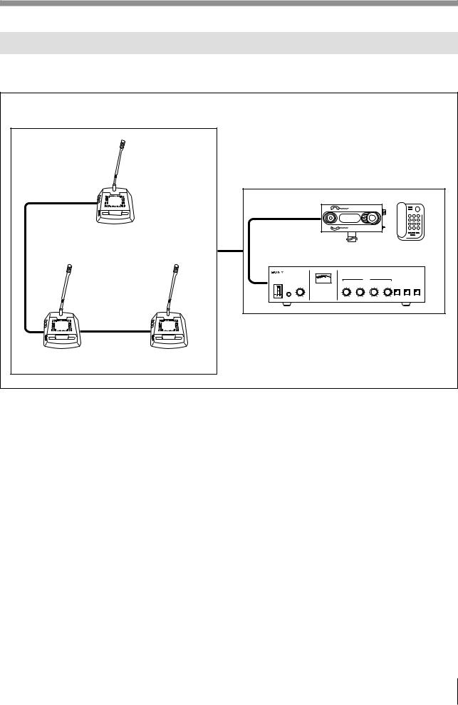
The figure below shows an example of the conference system.
Conference hall
Conference seats
Operator section |
|
|
|
|
|
|
|
|
|
|
|
|
|
|
|||||
SX-C100A |
|
SX-T100 |
|
|
|
|
|
|
|
|
|
|
|
|
|
|
|||
Chairman’s Unit a) |
|
Telephone Coupler |
|
|
|
|
|
|
|
|
|
|
|
|
|
||||
|
|
|
|
|
|
|
|
SX-M100 Control Unit |
|||||||||||
|
|
|
|
|
|
VU |
|
|
|
|
ORIGINAL |
|
|
|
|
|
|
|
|
|
|
|
|
MONITOR |
MIC/LINE 1 |
|
MIC/LINE 2 |
|
D/C UNIT MIC |
|
D/C UNIT SP |
|
|
||||||
|
POWER |
|
|
|
MONITOR |
|
|
|
|
|
|
|
|
|
|
|
MIC/LIMIT DIRECT ACCESS SEAT ASIGN |
||
I |
|
|
|
|
5 |
|
4 |
5 |
|
|
5 |
|
|
5 |
|
5 |
|
||
ON |
|
|
4 |
6 |
|
6 |
|
4 |
6 |
|
4 |
6 |
|
4 |
6 |
ON/OFF |
ON/OFF START/END |
||
|
|
3 |
|
7 |
3 |
|
7 |
3 |
|
7 |
3 |
|
7 |
3 |
|
|
7 |
|
|
|
|
|
PHONES |
|
|
|
|
|
|
|
|
|
|
|
|
|
|
|
|
|
|
|
2 |
|
8 |
2 |
|
8 |
2 |
|
8 |
2 |
|
8 |
2 |
|
|
8 |
|
O OFF |
1 |
|
9 |
1 |
|
9 |
1 |
|
9 |
1 |
|
9 |
1 |
|
|
9 |
|
||
MIN |
MAX |
0 |
10 |
0 |
10 |
0 |
10 |
0 |
10 |
|
|
||||||||
|
a) You can also use other combination of |
SX-D100A Delegate’s Unit a) |
the SX-C150/SX-D150. |
System configuration
5

Location and Function of Parts and Controls
SX-M100 Control Unit
Front panel |
|
|
|
|
|
|
|
|
|
|
|
|
|
|
|
|
|
||
1POWER switch |
|
|
|
|
|
|
|
|
5Volume controls |
|
|
||||||||
|
|
2PHONES connector |
|
|
|
|
|
|
|
|
|
|
|
6MIC LIMIT ON/OFF button |
|||||
|
|
3MONITOR volume control |
|
|
|
|
|
|
|
|
|
|
|
7DIRECT ACCESS |
|||||
|
|
|
|
|
4Level meter |
|
|
|
|
|
|
|
|
|
|
|
ON/OFF button |
||
|
|
|
|
|
|
|
|
|
|
|
|
|
|
|
|
|
|
8SEAT ASSIGN |
|
|
|
|
|
|
|
|
|
|
|
|
|
|
|
|
|
|
|
START/END button |
|
|
|
|
|
|
VU |
|
|
|
|
|
ORIGINAL |
|
|
|
|
|
|
|
|
|
|
MONITOR |
|
|
MIC/LINE 1 |
MIC/LINE 2 |
|
D/C UNIT MIC |
|
D/C UNIT SP |
|
|
|
||||||
|
|
|
|
|
|
|
|
|
|
||||||||||
|
POWER |
|
|
|
MONITOR |
|
|
|
|
|
|
|
|
|
|
|
MIC/LIMIT |
DIRECT ACCESS |
SEAT ASIGN |
I |
|
5 |
6 |
|
|
|
4 |
5 |
4 |
5 |
|
4 |
5 |
|
5 |
6 |
|||
ON |
4 |
|
|
|
6 |
6 |
|
6 |
|
4 |
ON/OFF |
ON/OFF |
START/END |
||||||
|
|
|
|
|
|
|
|
|
|
|
|
|
|
|
|||||
|
3 |
7 |
|
|
|
3 |
7 |
3 |
|
7 |
3 |
7 |
3 |
|
|
7 |
|
|
|
|
|
|
|
|
|
|
|
|
|
||||||||||
|
|
PHONES |
8 |
|
|
|
|
|
|
|
|
|
|
|
|
|
|
|
|
|
|
2 |
|
|
2 |
|
8 |
2 |
|
8 |
2 |
8 |
2 |
|
|
8 |
|
|
|
O OFF |
1 |
9 |
|
|
|
1 |
9 |
1 |
|
9 |
1 |
9 |
1 |
|
|
9 |
|
|
|
MIN |
MAX |
|
|
|
0 |
10 |
0 |
10 |
|
0 |
10 |
|
0 |
10 |
|
|
|
||
|
|
|
|
|
|
|
|
|
|
||||||||||
Rear panel |
|
|
|
|
|
|
|
|
|
|
|
|
|
|
|
|
|
||
|
9EXT UNIT IN/OUT connectors |
|
|
|
|
|
|
|
|
|
|
|
|
|
|
||||
|
|
|
0EXT IN-1 MIC/LINE connectors and MIC/LINE switch |
|
|
|
|
|
|
||||||||||
|
|
|
|
|
|
|
|
|
!¡LINE OUT!™TELEPHONE COUPLER connector |
||||||||||
|
|
|
|
|
|
|
|
|
connector |
|
|
|
|
|
|
|
|||
|
EXT UNIT |
EXT IN-1 |
|
|
|
|
LINE OUT |
@TELEPHONE COUPLER |
|
|
|
|
|
|
|||||
|
OUT |
MIC |
|
|
|
|
|
|
|
|
|
|
|
|
|
|
|
|
|
|
IN |
|
|
|
|
|
|
|
|
|
|
|
|
|
|
|
|
|
|
|
EXT IN-2 |
|
|
|
|
|
1 |
|
|
|
|
|
|
|
|
|
|
|
|
|
|
|
LINE |
|
|
|
|
|
|
|
|
|
|
|
|
|
|
||
|
MIC |
LINE |
|
|
|
|
|
|
|
|
|
|
|
|
|
|
|
|
|
|
|
|
|
|
|
2 |
|
|
|
|
|
|
|
|
|
|
|
||
|
MIC |
LINE |
MIC |
LINE |
|
|
|
|
|
|
|
|
|
|
|
|
|
|
|
|
|
|
|
|
|
|
|
|
|
|
|
|
|
|
|
||||
|
|
|
DELEGATE'S/CHAIRMAN'S UNIT |
|
|
|
|
|
|
|
|
|
|
|
AC IN |
|
|||
|
|
|
4 |
3 |
2 |
1 |
|
|
|
|
|
|
|
|
|
|
|
|
|
|
!£EXT IN-2 MIC/LINE |
|
|
|
|
|
|
|
|
|
|
|
|
!∞y terminal |
|
||||
|
|
connectors and |
|
|
|
|
|
|
|
|
|
|
|
|
|
|
|
|
|
|
|
MIC/LINE switch |
|
!¢DELEGATE’S/CHAIRMAN’S UNIT |
|
|
|
|
|
|
|
!§AC IN connector |
|||||||
|
|
|
|
|
connectors |
|
|
|
|
|
|
|
|
|
|
|
|
|
|
SX-M100 Control Unit
6

1 POWER switch
Setting the switch to ON (1 ) turns the power on. The level meter will light.
Setting the switch to OFF (o) turns the power off.
2 PHONES connector (stereo phone jack)
Connect 8-ohm stereo or monaural headphones. Note that the output is monaural even when stereo headphones are connected.
3 MONITOR volume control
Adjusts the volume of the headphones.
4 Level meter
Indicates the level of the audio signal output to the LINE OUT !¡, TELEPHONE COUPLER !™ and DELEGATE’S/CHAIRMAN’S UNIT !¢ connectors.
5 Volume controls
Used to adjust the level of the following sound.
D/C UNIT SP volume control: Adjusts the level of the audio signal output to the chairman’s unit/delegate’s unit.
D/C UNIT MIC volume control: Adjusts the input level of the audio signal sent from the microphones on the chairman’s units and delegate’s units.
MIC/LINE 1 volume control: Adjusts the input level of the signal input through the EXT IN-1 MIC or LINE connector.
MIC/LINE 2 volume control: Adjusts the input level of the signal input through the EXT IN-2 MIC or LINE connector.
When the MIC/LINE switch of the EXT IN-1 or EXT IN-2 connector is set to LINE, the input level of the signal input through the LINE connector can be adjusted.
When the MIC/LINE switch of the EXT IN-1 or EXT IN-2 connector is set to MIC, the input level of the signal input through the MIC connector can be adjusted.
6MIC (microphone mode) LIMIT ON/OFF button
Selects the microphone mode for the delegate’s units.
The microphone of the chairman’s unit remains live regardless of the setting of this button.
MIC (microphone) LIMIT ON: Press this button to set the microphone to the speaker’s number limitation mode. The button indicator lights. Setting this mode allows the microphones of up to five delegate’s units to be live at the same time.
MIC (microphone) LIMIT OFF: Press the button again to set the microphone to the speaker’s number unlimitation mode. The button indicator goes out. Setting this mode allows the microphones of all delegate’s units to be live at the same time.
7 DIRECT ACCESS ON/OFF button
This button is effective only when the SXA-120 Expansion Board (not supplied) is installed and the SX-8300/SX-S100 Microphone Control Panel is connected to the control unit.
While the SX-8300 is not connected, this button indicator lights, even though it is not operative. The button indicator does not go out even if you press this button.
8 SEAT ASSIGN START/END button
This button is effective only when the SXA-120 Expansion Board (not supplied) is installed and the SX-8300/SX-S100 Microphone Control Panel is connected to the control unit for performing seat assignment.
While the SX-8300 Microphone Control Panel is not connected, the button indicator does not light even if you press the button.
For details of the functions and how to use the DIRECT ACCESS ON/OFF and SEAT ASSIGN START/END buttons, refer to the manuals supplied with the SXA-120 Expansion Board.
9EXT UNIT IN/OUT (external unit input/ output) connectors (phone jack)
Connect to the howling suppressor unit or filter unit (not supplied).
Notes
•Be sure to connect both the IN and OUT connectors. Connecting only one of the two connectors results in incorrect operation of the unit.
•When it is not necessary to use the howling suppressor or filter unit, disconnect cables from both connectors.
7

Location and Function of Parts and Controls
0EXT IN-1 MIC/LINE (external 1 microphone/ line signal input) connectors and MIC/LINE
switch
EXT IN-1 MIC/LINE connectors
Accept an external audio signal.
MIC connector (XLR type): Connect a rostrum or conference hall microphone.
Note
When you use a connecting cable with an XLR connector, pin No.1 and the case (metal part) of which are connected, noise may be picked up.
LINE connector (phono jack): Connect to external equipment such as audio equipment.
MIC/LINE switch
Selects the signal input to the EXT IN-1 connector. MIC: Set the switch to this position when a
microphone is connected.
LINE: Set the switch to this position when an item of audio equipment is connected.
!¡LINE OUT (line output) connectors
(phono jacks)
Supply the signal from the chairman’s unit/ delegate’s unit, that from the rostrum or conference hall microphone. There are two connectors. Use these connectors when recording the output to a tape recorder or when sending the line output to the monitor system transmitter by means of an infrared or induction-based system.
!™ TELEPHONE COUPLER connector (6-pin multi-connector)
Connect to the SX-T100 telephone coupler (not supplied).
!£EXT IN-2 MIC/LINE (external 2 microphone/ line signal input) connectors and MIC/ LINE (microphone/line signal select) switch
EXT IN-2 MIC/LINE connectors
Input an external audio signal.
MIC connector (phone jack): Connect a rostrum or conference hall microphone.
LINE connector (phono jack): Connect to external equipment such as audio equipment.
MIC/LINE switch
Selects the signal input to the EXT IN-2 connector. MIC: Set the switch to this position when a
microphone is connected.
LINE: Set the switch to this position when an item of audio equipment is connected.
!¢DELEGATE’S/CHAIRMAN’S UNIT connectors (20-pin multi-connectors)
Connect to the SX-C100A/SX-C150/SX-D100A/ SX-D150 Chairman’s Unit/Delegate’s Unit. The same signal is output from four connectors. Up to 15 SX-C100A/D100A units can be connected to each of the four connectors. Thus, up to 60 SX- C100A/SX-C150/SX-D100A/SX-D150 units can be connected.
!∞y (signal ground) terminal
Ground if necessary.
!§AC IN (AC power input) connector
Connect the unit to an AC power source by means of the supplied AC power cord.
8
 Loading...