


 Loading...
DIGITAL VIDEOCASSETTE RECORDER
DVW-M2000 DVW-M2000P DVW-2000
DVW-2000P
Note
The supplied CD-ROM includes operation manuals for the DVW-2000 series of digital videocassette recorders (English, Japanese, French and German versions). For more details, see page 1-5 “Using the CD-ROM Manual.”
TM
OPERATION MANUAL [English] 1st Edition (Revised 2)

WARNING
To prevent fire or shock hazard, do not expose the unit to rain or moisture.
To avoid electrical shock, do not open the cabinet. Refer servicing to qualified personnel only.
THIS APPARATUS MUST BE EARTHED.
AVERTISSEMENT
Afin d’éviter tout risque d’incendie ou d’électrocution, ne pas exposer cet appareil à la pluie ou à l’humidité.
Afin d’écarter tout risque d’électrocution, garder le coffret fermé. Ne confier l’entretien de l’appareil qu’à un personnel qualifié.
CET APPAREIL DOIT ÊTRE RELIÉ À LA TERRE.
VORSICHT
Um Feuergefahr und die Gefahr eines elektrischen Schlages zu vermeiden, darf das Gerät weder Regen noch Feuchtigkeit ausgesetzt werden.
Um einen elektrischen Schlag zu vermeiden, darf das Gehäuse nicht geöffnet werden. Überlassen Sie Wartungsarbeiten stets nur einem Fachmann.
DIESES GERÄT MUSS GEERDET WERDEN.
For the customers in the USA
This equipment has been tested and found to comply with the limits for a Class A digital device, pursuant to Part 15 of the FCC Rules. These limits are designed to provide reasonable protection against harmful interference when the equipment is operated in a commercial environment. This equipment generates, uses, and can radiate radio frequency energy and, if not installed and used in accordance with the instruction manual, may cause harmful interference to radio communications. Operation of this equipment in a residential area is likely to cause harmful interference in which case the user will be required to correct the interference at his own expense.
You are cautioned that any changes or modifications not expressly approved in this manual could void your authority to operate this equipment.
The shielded interface cable recommended in this manual must be used with this equipment in order to comply with the limits for a digital device pursuant to Subpart B of Part 15 of FCC Rules.
This symbol is intended to alert the user to the presence of important operating and maintenance (servicing) instructions in the literature accompanying the appliance.
WARNING: THIS WARNING IS APPLICABLE FOR USA ONLY.
If used in USA, use the UL LISTED power cord specified below.
DO NOT USE ANY OTHER POWER CORD.
Plug Cap |
Parallel blade with ground pin (NEMA |
|
5-15P Configuration) |
Cord |
Type SJT, three 16 or 18 AWG wires |
Length |
Minimum 1.5 m Less than 2.5 m (8 ft |
|
3 in) |
Rating |
Minimum 10 A, 125 V |
Using this unit at a voltage other than 120V may require the use of a different line cord or attachment plug, or both. To reduce the risk of fire or electric shock, refer servicing to qualified service personnel.
WARNING: THIS WARNING IS APPLICABLE FOR OTHER COUNTRIES.
1.Use the approved Power Cord (3-core mains lead)/ Appliance Connector/Plug with earthing-contacts that conforms to the safety regulations of each country if applicable.
2.Use the Power Cord (3-core mains lead)/Appliance Connector/Plug conforming to the proper ratings (Voltage, Ampere).
If you have questions on the use of the above Power Cord/ Appliance Connector/Plug, please consult a qualified service personnel.
AVERTISSEMENT: CET AVERTISSEMENT EST VALABLE POUR LES AUTRES PAYS.
1.Utiliser un cordon d’alimentation approuvé (conducteur d’alimentation 3 âmes)/connecteur d’appareil/prise avec contacts de mise à la terre conforme aux règles de sécurité de chaque pays si applicable.
2.Utiliser un cordon d’alimentation approuvé (conducteur d’alimentation 3 âmes)/connecteur d’appareil/prise conforme aux valeurs nominales (tension, ampérage) correctes.
S’adresser à un personnel de service qualifié pour toute question concernant l’emploi du cordon d’alimentation/ connecteur d’appareil/prise ci-dessus.
WARNUNG: DIESE WARNUNG GILT FÜR ANDERE LÄNDER.
1.Verwenden Sie Netzkabel (dreiadrig), Geräteanschlüsse und Netzkabelstecker mit Masseleitung, die den Sicherheitsrichtlinien des jeweiligen Landes entspricht.
2.Verwenden Sie Netzkabel (dreiadrig), Geräteanschlüsse und Netzkabelstecker mit Masseleitung, die den vor Ort herrschenden Spannungsanforderungen (Spannug, Stromstärke) entsprechen.
Bei Frage über die Eignung und Sicherheit von Netzkabeln (dreiadrig), Geräteanschlüssen und Netzkabelsteckern wenden Sie sich bitte an einen qualifizierten Electrotechniker.
CAUTION
The apparatus shall not be exposed to dripping or splashing and no objects filled with liquid, such as vases, shall be placed on the apparatus.
ATTENTION
Eviter d’exposer l’appareil à un égouttement ou à des éclaboussures et ne placer aucun objet rempli de liquide, comme un vase, sur l’appareil.
ACHTUNG
Das Gerät ist nicht tropfund spritzwassersicher, daher dürfen keine mit Flüssigkeiten gefüllten Gegenstände, z. B. Vasen, darauf abgestellt werden.
CAUTION
The unit is not disconnected from the AC power source (mains) as long as it is connected to the wall outlet, even if the unit itself has been turned off.
ATTENTION
Cet appareil n’est pas déconnecté de la source d’alimentation secteur tant qu’il est raccordé à la prise murale, même si l’appareil lui-même a été mis hors tension.
ACHTUNG
For the customers in Europe
This product with the CE marking complies with both the EMC Directive (89/336/EEC) and the Low Voltage Directive (73/23/EEC) issued by the Commission of the European Community.
Compliance with these directives implies conformity to the following European standards:
•EN60065: Product Safety
•EN55103-1: Electromagnetic Interference (Emission)
•EN55103-2: Electromagnetic Susceptibility (Immunity) This product is intended for use in the following Electromagnetic Environment (s):
E1 (Residential), E2 (Commercial and light industrial), E3 (Urban outdoors) and E4 (Controlled EMC environment ex. TV studio).
Pour les clients européens
Ce produit portant la marque CE est conforme à la fois à la Directive sur la compatibilité électromagnétique (EMC) (89/ 336/CEE) et à la Directive sur les basses tensions (73/23/ CEE) émises par la Commission de la Communauté européenne.
La conformité à ces directives implique la conformité aux normes européennes suivantes:
•EN60065: Sécurité des produits
•EN55103-1: Interférences électromagnétiques (émission)
•EN55103-2: Sensibilité électromagnétique (immunité) Ce produit est prévu pour être utilisé dans les environnements électromagnétiques suivants:
E1 (résidentiel), E2 (commercial et industrie légère), E3 (urbain extérieur) et E4 (environnement EMC contrôlé, ex. studio de télévision).
Für Kunden in Europa
Dieses Produkt besitzt die CE-Kennzeichnung und erfüllt die EMV-Direktive (89/336/EMG) der EG-Kommission als auch die Direktive Niederspannung (73/23/EMG).
Angewandte Normen:
•EN60065: Produktsicherheit
•EN55103-1: Elektromagnetische Verträglichkeit (Störaussendung)
•EN55103-2: Elektromagnetische Verträglichkeit (Störfestigkeit)
für die folgenden elektromagnetischen Umgebungen:
E1 (Wohnbereich), E2 (kommerzieller und in beschränktem maße industrieller Bereich), E3 (Stadtbereich im Freien) und E4 (kontrollierter EMV-Bereich, z.B. Fernsehstudio).
Solange das Netzkabel an eine Netzsteckdose angeschlossen ist, bleibt das Gerät auch im ausgeschalteten Zustand mit dem Strommetz verbunden.

Table of Contents
Chapter 1
Overview
Chapter 2
Location and Function of
Parts
Chapter 3
Preparations
Chapter 4
Recording and Playback
Chapter 5
Editing
1-1 |
Features ........................................................................................... |
1-1 |
|
1-2 |
Example System Configuration .................................................... |
1-4 |
|
1-3 |
Using the CD-ROM Manual .......................................................... |
1-5 |
|
|
1-3-1 |
CD-ROM System Requirements ............................................ |
1-5 |
|
1-3-2 |
Preparations ............................................................................ |
1-5 |
|
1-3-3 |
Reading the CD-ROM Manual .............................................. |
1-5 |
2-1 Control Panels................................................................................. |
2-1 |
2-1-1 Upper Control Panel............................................................... |
2-2 |
2-1-2 Lower Control Panel .............................................................. |
2-3 |
2-1-3 Switch Panel ......................................................................... |
2-14 |
2-2 Connector Panel ........................................................................... |
2-15 |
3-1 Connections to External Devices ................................................... |
3-1 |
3-1-1 Connections to Digital Devices .............................................. |
3-1 |
3-1-2 Connections to Analog Devices ............................................. |
3-2 |
3-2 Reference Signals for Video Output and Servo System .............. |
3-3 |
3-2-1 External Sync Signal for the Internal Reference Video Signal |
|
Generator ................................................................................ |
3-3 |
3-2-2 Reference Signal for the Servo System .................................. |
3-4 |
3-2-3 Connecting Reference Signals ............................................... |
3-5 |
3-3 Setup ................................................................................................ |
3-7 |
3-4 Superimposed Character Information ......................................... |
3-8 |
3-5 Cassettes ........................................................................................ |
3-10 |
3-5-1 Cassette Types ...................................................................... |
3-10 |
3-5-2 Inserting and Ejecting Cassettes .......................................... |
3-10 |
3-5-3 Preventing Accidental Erasure of Recordings...................... |
3-11 |
3-6 Using a Memory Stick .................................................................. |
3-12 |
3-6-1 Notes on Memory Stick ....................................................... |
3-12 |
4-1 Recording ........................................................................................ |
4-1 |
4-1-1 Preparations for Recording .................................................... |
4-1 |
4-1-2 Recording Time Code and User Bit Values ............................ |
4-2 |
4-1-3 Recording Procedure .............................................................. |
4-5 |
4-2 Playback .......................................................................................... |
4-6 |
4-2-1 Preparations for Playback ...................................................... |
4-6 |
4-2-2 Playback Procedures .............................................................. |
4-7 |
4-2-3 Dynamic Motion Control (DMC) Playback......................... |
4-11 |
5-1 Automatic Editing .......................................................................... |
5-1 |
5-1-1 Overview ................................................................................ |
5-1 |
5-1-2 Switch and Menu Settings...................................................... |
5-2 |
5-1-3 Selecting the Editing Mode .................................................... |
5-3 |
5-1-4 Setting Edit Points .................................................................. |
5-3 |
5-1-5 Modifying and Deleting Edit Points ...................................... |
5-6 |
5-1-6 Cue-Up to Edit Points and Preroll.......................................... |
5-7 |
5-1-7 Preview ................................................................................... |
5-7 |
5-1-8 Carrying Out Automatic Editing ............................................ |
5-8 |
(Continued)
Table of Contents |
1 |

Table of Contents
Chapter 5
Editing (Continued)
Chapter 6
Shot Mark Function
Chapter 7
Tele-File
Chapter 8
UMID Functions
Chapter 9
Essence Marks
Chapter 10
Auto Event Detector
|
|
|
.................................................................................5-2 DMC Editing |
5-11 |
|
|
|
5-2-1 Overview of DMC Editing ................................................... |
5-11 |
|
|
|
5-2-2 Carrying Out DMC Editing.................................................. |
5-12 |
|
|
|
5-3 Special Automatic Editing Methods ........................................... |
5-13 |
|
|
|
5-3-1 Quick Editing ....................................................................... |
5-13 |
|
|
|
5-3-2 Continuous Editing .............................................................. |
5-13 |
|
|
|
5-3-3 Standalone Editing ............................................................... |
5-14 |
|
|
|
5-3-4 Manual Editing ..................................................................... |
5-14 |
|
|
|
5-3-5 Preread Editing ..................................................................... |
5-14 |
|
|
|
6-1 Overview.......................................................................................... |
6-1 |
|
|
|
6-2 Shot Mark Operation Menu .......................................................... |
6-2 |
|
|
|
6-3 Shot Mark Operations ................................................................... |
6-3 |
|
|
|
6-3-1 Reading Shot Marks ............................................................... |
6-3 |
|
|
|
6-3-2 Writing Shot Marks ................................................................ |
6-3 |
|
|
|
6-3-3 Shot Mark List Operations ..................................................... |
6-4 |
|
|
|
6-3-4 Cueing Up to Shot Marks....................................................... |
6-6 |
|
|
|
6-3-5 Reading In Shot Data ............................................................. |
6-7 |
|
|
|
6-3-6 Sorting Shot Marks ................................................................ |
6-8 |
|
|
|
7-1 Overview of Tele-File Functions .................................................... |
7-1 |
|
|
|
7-2 Opening the Tele-File Menu .......................................................... |
7-2 |
|
|
|
7-3 Tele-File Menu ................................................................................ |
7-3 |
|
|
|
7-3-1 Clip Data Display ................................................................... |
7-3 |
|
|
|
7-3-2 Preroll and Cue Up Using Clip Data ...................................... |
7-6 |
|
|
|
7-3-3 Modifying Clip Data .............................................................. |
7-7 |
|
|
|
7-3-4 Undo/Resume Functions ...................................................... |
7-10 |
|
|
|
7-3-5 Displaying and Modifying Attribute Data ........................... |
7-11 |
|
|
|
8-1 Overview of UMID Functions ....................................................... |
8-1 |
|
|
|
8-2 Recording UMIDs .......................................................................... |
8-2 |
|
|
|
8-3 UMID Output and Display ............................................................ |
8-4 |
|
|
|
8-3-1 UMID Output Settings ........................................................... |
8-4 |
|
|
|
8-3-2 UMID Display........................................................................ |
8-4 |
|
|
|
9-1 Overview of Essence Mark Functions .......................................... |
9-1 |
|
|
|
9-2 Essence Mark Recording and Output .......................................... |
9-2 |
|
|
|
9-2-1 Essence Mark Recording ....................................................... |
9-2 |
|
|
|
9-2-2 Essence Mark Output ............................................................. |
9-2 |
|
|
|
10-1 Overview of Auto Event Detector Functions............................ |
10-1 |
|
|
|
10-2 Event Output and Recording .................................................... |
10-1 |
|
|
|
|
|
|
|
|
|
|
2 Table of Contents

6-1
Chapter 11 |
|
...............................................11-1 Overview of the Function Menu |
11-1 |
Function Menu |
|
...........................................11-1-1 Function Menu Configuration |
11-1 |
|
11-1-2 Using the Function Menu |
11-2 |
|
|
|
||
|
|
11-2 Function Menu Item List ........................................................... |
11-3 |
|
|
12-1 Setup Menu Configuration |
12-1 |
Chapter 12 |
|||
Setup Menus |
|
12-2 Setup Menu Operations ............................................................. |
12-2 |
|
|
12-3 Items in the Basic Setup Menu .................................................. |
12-5 |
|
|
12-4 Items in the Extended Setup Menu........................................... |
12-8 |
|
|
13-1 Overview of Setup Utility Menu Functions |
13-1 |
Chapter 13 |
|||
Setup Utility Menu |
|
13-1-1 Using Memory Stick Data ................................................. |
13-1 |
Functions |
|
|
|
|
|
14-1 Removing a Cassette When Tape Slack Occurs |
14-1 |
Chapter 14 |
|||
Maintenance and |
|
14-2 Head Cleaning ............................................................................ |
14-1 |
|
14-3 Error Messages |
14-2 |
|
Inspection |
|
||
|
14-4 Moisture Condensation |
14-4 |
|
|
|
||
|
|
14-5 Regular Checks........................................................................... |
14-5 |
|
|
14-5-1 Digital Hours Meter ........................................................... |
14-5 |
|
|
14-5-2 Maintenance Timings ........................................................ |
14-6 |
|
|
Specifications |
A-1 |
Appendix |
|
||
|
|
Index ....................................................................................................... |
I-1 |
|
Table of Contents |
3 |
|
1-1 Features
The DVW-M2000/M2000P/2000/2000P is a digital videocassette recorder based on the digital Betacam format.
This unit uses large scale integrated circuits for signal processing, and has a simple internal construction, allowing it to provide functionality at least equivalent to a conventional VTR in a compact (4U size),
lightweight, and low power consumption design. It not only offers recording and playback in digital
Betacam format, but can also play back tapes recorded in Betacam SX format, analog Betacam format, or MPEG IMX format 1).
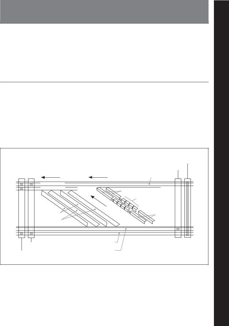
Digital Betacam format
The digital Betacam format is characterized in that the video and four-channel audio signals of each field are recorded onto the tape with six helical tracks, at a slightly slower tape speed and three times faster drum rotation speed than the analog Betacam formats: Betacam, and Betacam SP.
As for longitudinal tracks, the digital Betacam format has a CTL track, a time code (LTC) track and a cue audio track, similarly to the analog Betacam formats.
However, it does not have a channel-1 audio track, and this is a solution to expand the space for the helical tracks.
Digital Betacam VTRs have a greater drum diameter than that of analog Betacam ones to ensure optimum digital recording, but their built-in time base corrector circuit enables them to play analog Betacam tapes (analog Betacam playback compatibility).
|
|
Full erase head |
|
|
CTL head |
Betacam SP tape pattern |
Digital Betacam tape pattern |
Cue audio |
|
|
|
Channel-2 audio |
|
|
Channel-1 audio |
|
Video |
|
|
|
|
|
Channel-1 to |
|
|
Channel-4 audio |
Y track |
|
Video |
|
|
|
C track |
|
|
Cue/time code erase head |
Time code |
|
|
|
|
Audio/time code record/playback head |
CTL (control) |
|
|
|
..........................................................................................................................................................................................................
1)The DVW-2000/2000P does not support these three formats (Betacam SX, analog Betacam, MPEG IMX).
ChapterapterC1
1Overview Overview
Chapter 1 Overview 1-1

Overview 1 Chapter
1-1 Features
High-performance heads and compatibility playback function
The newly developed high-performance heads and dynamic tracking (DT) technology provide highdensity recording and playback in narrow tracks with high reliability. In addition to the digital Betacam recording and playback heads, this unit is also equipped with Betacam SX format playback heads, MPEG IMX playback heads, and analog Betacam DT heads, to provide compatibility playback functions, and allowing a wide variety of recorded resources to be used effectively.
Note that the compatibility playback functions differ depending on the models covered by this manual. 1)
High-precision digital signal processing and range of interfaces
While supporting a wide range of input and output signals, all of the VTR internal processing is digital, providing high stability and reliability.
The audio signals, similarly, are based on AES/EBU format, and are subjected to digital signal processing while still uncompressed.
The following interfaces are standard equipment, for ease of connection to different external devices.
•Analog composite signal input/output
•Analog component signal input/output
•Analog audio signal input/output (4 channels)
•SDI (Serial Digital Interface) SMPTE 259M input (component digital video/audio (4 channels))
•SDI SMPTE 259M output (component digital video/ audio (DVW-M2000/M2000P: 8 channels; DVW2000/2000P: (4 channels))
•AES/EBU serial digital audio input (4 channels)
•AES/EBU serial digital audio output (DVW-M2000/ M2000P: 8 channels; DVW-2000/2000P: 4 channels)
•Time code input/output
•Cue audio signal input/output
High quality four-channel audio
High quality 20 bit/48 kHz digital audio is supported. There are four digital audio input/output channels, and four analog audio input/output channels.
Newly developed multifunction control panel
While a compact 4U size, this unit has a front panel which provides a wide range of functions while maintaining existing operability.
Basic operation buttons and jog/shuttle dial
The basic buttons and jog/shuttle dial for VTR and editing operations are provided in the conventional VTR layout, ensuring continuity with conventional operating panels.
Time data display
This can be selected to display a CTL counter value, time code value, or time code user bits. It can also display edit points and edit durations.
Menu-based control interface
The time data/menu display shows not only various values and settings, but also the pages of a menu system for commonly used functions. You can use the function keys and MULTI CONTROL knob to easily change settings.
Other operation settings, including interfacing with external devices, can be set from the control panel by the same type of setup menu system as on a conventional VTR.
..........................................................................................................................................................................................................
1)The DVW-2000/2000P is equipped with no Betacam SX playback heads, no analog Betacam DT playback heads, and no MPEG IMX playback heads.
1-2 Chapter 1 Overview

High quality variable speed playback and digital jog sound function
In digital Betacam or MPEG IMX format1) playback, the dedicated playback DT heads allow smooth, noiseless playback from –1 to +3 times normal speed. In analog Betacam compatible playback also, similar dedicated DT heads allow noiseless playback from –1 to +3 times normal speed, and in Betacam SX format1) compatible playback, special multi-head playback technology allows noiseless playback from –1 to +2 times normal speed.
In slow motion operation, the digital jog sound function provides the same ease of operation as a conventional analog VTR.
Wide range of editing functions
By combining two units, you can carry out both assemble editing and insert editing automatically. All of the necessary editing functions are provided to set and amend edit points, to preview and review results of editing, and so on.
DMC editing
This allows automatic editing with a varying playback speed memorized beforehand for an edit segment.
Split editing
In insert editing, this allows editing with the audio IN and OUT points to be displaced from the video edit points.
Preread editing
This allows you to play back prerecorded video and audio material, edit it by applying effects with an external device, and then rerecord in real time on the same tape.
Cross-fade editing
In audio editing, to avoid unnatural effects at edit points, you can fade the audio track. The setting allows you to select fade-in, fade-out, or cut-in.
Tele-File functions
Tele-File enables data writing/reading between cassettes with memory labels and VTRs. It increases the efficiency of operations such as recording, playback and editing, and source data management.
Remote control function
This unit can be controlled from an external remote controller or editor through an interface complying with RS-422A (serial 9-pin). Since two remote control connectors are provided, you can also control a number of VTRs simultaneously.
Additionally, a parallel (50-pin) interface is also fitted as standard, supporting easy external control through the parallel interface.
Rack mounting
Using the optional RMM-131 Rack Mount Adaptor, you can mount the unit in a standard EIA 19-inch rack.
For details of rack mounting, refer to the Installation Manual.
..........................................................................................................................................................................................................
1)The MPEG IMX and Betacam SX formats are not supported by the DVW-2000/2000P.
Overview 1 Chapter
Chapter 1 Overview 1-3
Overview 1 Chapter
1-1-2FeaturesExample System Configuration
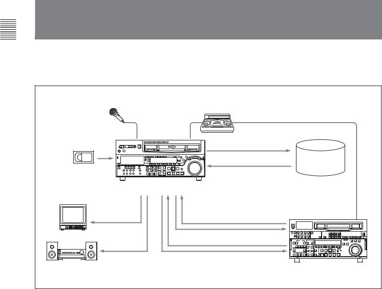
The following conceptual diagram shows an example of use.
Microphone |
BVE-series editor |
|
|
|
|
|
Tape control |
|
Digital/analog cassette |
|
|
|
SDI |
Audio/video |
|
server |
|
|
|
|
|
|
system |
DVW-M2000/M2000P/2000/2000P |
|
|
Video monitor |
|
|
Analog composite |
|
|
|
Analog composite/component |
|
Analog audio |
SDI |
|
|
|
|
Audio monitor |
|
VTR with SDI connectors |
|
|
or analog VTR |
1-4 Chapter 1 Overview
1-3 Using the CD-ROM Manual
The supplied CD-ROM includes operation manuals for the DVW-2000 series of digital videocassette recorders (English, Japanese, French, and German versions).
1-3-1 CD-ROM System
Requirements
The following are required to access the supplied CDROM disc.
•Computer: PC with Intel Pentium CPU
-Installed memory: 64 MB or more
-CD-ROM drive: × 8 or faster
•Monitor: Monitor supporting resolution of 800 × 600 or higher
•Operating system: Microsoft Windows Millennium Edition, Windows 2000 Service Pack 2, Windows XP Professional or Windows XP Home Edition
When these requirements are not met, access to the CD-ROM disc may be slow, or not possible at all.
1-3-2 Preparations
One of the following programs must be installed on your computer in order to use the operation manuals contained on the CD-ROM disc.
•Adobe Acrobat Reader Version 4.0 or higher
•Adobe Reader Version 6.0 or higher
Note
If Adobe Reader is not installed, you can download it from the following URL: http://www.adobe.com/products/acrobat/ readstep2.html
1-3-3 Reading the CD-ROM
Manual
To read the operation manual contained on the CDROM disc, do the following.
1Insert the CD-ROM disc in your CD-ROM drive.
A cover page appears automatically in your browser. If it does not appear automatically in the browser, double-click the index.htm file on the CD-ROM disc.
2Select and click the operation manual that you want to read.
This opens the PDF file of the operation manual.
Note
If you lose the CD-ROM disc or become unable to read its content, for example because of a hardware failure, you can do one of the following.
You can purchase a new CD-ROM disc to replace one that has been lost or damaged. Contact your Sony service representative.
Overview 1 Chapter
.........................................................................................................................................................................................................
•Intel and Pentium are registered trademarks of Intel Corporation or its subsidiaries in the United States and other countries.
•Microsoft and Windows are registered trademarks of Microsoft Corporation in the United States and/or other countries.
•Adobe, Acrobat, and Adobe Reader are trademarks of Adobe Systems Incorporated in the United States and/or other countries.
Chapter 1 Overview 1-5
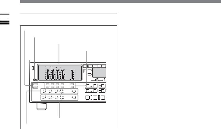
2-1 Control Panels
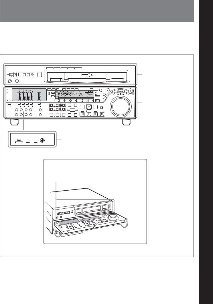
There are three control panels, as follows:
•Upper control panel
•Lower control panel
•Switch panel
Z |
Upper control panel (see page 2-2) |
VID. IN PB/EE |
CONFI |
CTL/TC MENU TCGSET |
Y-R,B PB |
OFF |
TC |
Lower control panel (see page 2-3)
CONTROL PANEL |
Switch panel (access by opening the lower control panel) (see page 2-14) |
KEY INHI |
PANEL SEL |
ON OFF REAR FRONT
Lower control panel unlock buttons
Pushing in these buttons allows you to open the lower control panel.
2 Chapter
LocationChapter2Lation andFunction andofParts Functionof
artsP
Chapter 2 Location and Function of Parts |
2-1 |
Parts of Function and Location 2 Chapter
2-1 |
Control Panels |
|
|
||
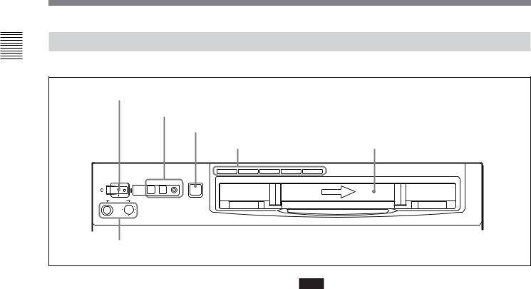
2-1-1 Upper Control Panel |
|
|
|||
|
1 POWER switch |
|
|
||
|
|
2 REMOTE buttons and RS-232C indicator |
|
||
|
|
|
3 EJECT button |
|
|
|
|
|
4 Format indicators |
Cassette compartment |
|
|
|
|
|
||
|
|
|
BETACAM/SP BETACAM SX MPEG IMX |
Digital BETACAM |
|
|
POWER |
REMOTE |
EJECT |
|
|
|
|
1(9P) 2(50P) |
RS-232C |
|
|
|
|
|
Z |
|
|
|
PHONES |
|
|
|
|
|
5 PHONES jack and control |
|
|
||
1 POWER switch
Pressing the ‘ ) ’ side of the switch powers the unit on. When the unit is powered on, the audio setting display section (see page 2-5) and the time data/menu display section (see page 2-7) light.
2 REMOTE buttons and RS-232C indicator
Press one of these buttons to select the device controlling this unit.
1(9P): This unit is controlled by the device connected to the REMOTE 1-IN(9P) or REMOTE 1- OUT(9P) connector. The button lights.
2(50P): This unit is controlled by the device connected to the REMOTE 2 PARALLEL I/ O(50P) connector. The button lights.
RS-232C indicator: This indicator lights when this unit is controlled through the RS-232C connector.
3 EJECT button
To eject the cassette, press this button. While the cassette is being ejected, this button lights.
When using the lower control panel as remote control panel, press the DELETE button and STOP button at the same time to eject the cassette.
Note
Ejecting with the EJECT button is a local operation. It is not possible to eject a cassette in another unit by remote control.
4 Format indicators
The BETACAM/SP, BETACAM SX, MPEG IMX, or Digital BETACAM indicator1) lights depending on the current recording or playback format.
The BETACAM/SP indicator lights when the format is Betacam or Betacam SP.
5 PHONES jack and control
Connect stereo headphones with an impedance of 8 ohms, to monitor the sound during recording, playback and editing.
The control knob adjusts the volume.
It is possible to set an internal board switch so that the output volume from the MONITOR OUTPUT L and R connectors is controlled simultaneously.
For details, refer to the Installation Manual.
..........................................................................................................................................................................................................
1)The BETACAM/SP, BETACAM SX, and MPEG IMX indicators do not exist on the DVW-2000/2000P.
2-2 |
Chapter 2 Location and Function of Parts |

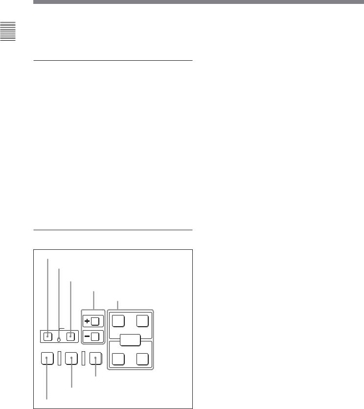
2-1-2 Lower Control Panel
|
|
4Time data/menu display section (see page 2-7) |
|
|
2CHANNEL CONDITION |
5MULTI CONTROL knob and SHIFT |
|
|
indicator (see page 2-6) |
indicator (see page 2-8) |
|
1Audio control section |
3Menu control buttons |
6RESET button (see page 2-8) |
|
(see page 2-4) |
|||
(see page 2-6) |
|
||
|
|
||
|
VID. IN PB/EE CONFI CTL/TC MENU TCGSET |
||
|
Y-R,B PB OFF TC |
|
|
7Search control section (see page 2-8)
8REC INHI indicator (see page 2-10)
9Tape transport control section (see page 2-10)
qaALARM indicator and KEY INHI indicator (see page 2-11)
q;Editing mode setting |
qsPLAYER button and RECORDER |
section (see page 2-11) |
button (see page 2-12) |
VID. IN PB/EE |
CONFI |
CTL/TC MENU TCGSET |
Y-R,B PB |
OFF |
TC |
qdEditing control section (see page 2-12)
qfShot mark section (see page 2-13)
Parts of Function and Location 2 Chapter
Chapter 2 Location and Function of Parts |
2-3 |
Parts of Function and Location 2 Chapter
2-1 Control Panels
1 Audio control section
1 Audio selection function selector buttons |
2 DISPLAY FULL/FINE button |
3 Audio setting display section |
4 Audio signal |
selection buttons |
6 PB controls |
5 REC controls |
In the audio control section, you can select and display input and output signals for audio channels.
1 Audio selection function selector buttons INPUT (input signal selection mode) button:
Pressing this button puts the unit into input signal selection mode. In the audio setting display section, indicators flash to indicate the currently selected signal for each channel (SDI, AES/EBU, or ANA). In this state, you can use the audio signal selection buttons to select the signal to input to each channel.
You can select the following signals for audio input channels 1 to 4, respectively.
•For input channel 1: SDI-1, SDI-5, AES/EBU-1, or ANALOG-1
•For input channel 2: SDI-2, SDI-6, AES/EBU-2, or ANALOG-2
•For input channel 3: SDI-3, SDI-7, AES/EBU-3, or ANALOG-3
•For input channel 4: SDI-4, SDI-8, AES/EBU-4, or ANALOG-4
Pressing this button again takes the unit out of input signal selection mode and puts it into monitor signal selection mode.
MIXING (mixing setting mode) button: Pressing this button puts the unit into mixing setting mode. In the audio setting display section, the MIX indicator flashes. In this state, you can use the audio signal selection buttons to specify which input channel signal will be recorded on which audio track on the tape.
Pressing this button again takes the unit out of mixing setting mode and puts it into monitor signal selection mode.
On how to operate in input signal selection mode, mixing setting mode, and monitor signal selection mode, see the descriptions of the audio signal selection buttons on page 2-5.
2 DISPLAY FULL/FINE button
Pressing this button toggles the display mode of the level meters in the audio setting display section between FULL and FINE.
FULL: The display covers the range –60 dB to 0 dB or –40 dB to +20 dB as selected using setup menu item 806. In this mode the segment of the display corresponding to the current audio level and all lower segments light.
FINE: The display is enlarged, with a step of
0.25 dB. A segment indicating the reference level lights. In this mode only the segment of the display corresponding to the current audio level lights. If the audio level exceeds the maximum display level, the top segment flashes, and if the audio level goes below the minimum display level, the bottom segment flashes.
2-4 |
Chapter 2 Location and Function of Parts |
3 Audio setting display section
Input signal indicator
|
|
|
|
|
|
|
SDI |
|
||||||
DATA indicator |
AES/EBU/ANA |
|
||||||||||||
|
|
|
|
DATA |
5 6 7 8 |
|
Input channel |
|||||||
MIX indicator |
|
|
MIX |
1 2 3 4 |
|
indicator |
||||||||
|
|
|
|
dB |
|
|
|
|
dB |
|||||
|
|
|
|
OVER |
|
|||||||||
OVER indicator |
0 |
|
|
|
|
20 |
|
|
||||||
|
|
|
||||||||||||
|
|
|
|
|
|
|
|
|
2 |
|
|
|
|
|
|
|
|
|
|
|
|
|
|
|
|||||
|
|
|
|
-10 |
|
|
|
110 |
|
|
||||
|
|
|
|
|
|
|
||||||||
|
|
|
|
|
|
|
|
|||||||
|
|
|
|
|
|
|
|
|||||||
Level meter |
|
|
|
-20 |
|
|
|
|
|
|
|
|
|
|
|
|
|
|
|
|
|
|
|
|
|||||
|
|
|
|
|
|
0 |
|
|
|
|
||||
|
|
|
|
|
|
|
|
|
||||||
-1 -30

 -10
-10
-40

 -20
-20 

 -2
-2
-60

 -40
-40
 L
L 
 EMPH
EMPH
 R
R
Monitor channel L and R indicators
EMPH indicator
Input signal indicator: Indicates the currently selected input signal (‘SDI’, ‘AES/EBU’, ‘ANA’ for analog) for the corresponding audio input channel.
DATA indicator: Lights when the corresponding audio track (audio channel on the tape) is put into data mode.
For details of the data mode, refer to the Maintenance Manual Volume 1.
MIX (mixing) indicator: Flashes when a mixing setting operation is enabled for the corresponding audio track. The indicator showing the number of the selected input channel lights.
OVER indicator: While the unit is in recording or playback mode, this lights when the level of the audio signal on the corresponding channel exceeds the maximum level that can be indicated on the level meter.
Level meter: Displays the audio signal level when the unit is in recording, E-E1), or playback mode. You can use the setup menu to switch the display mode between PEAK.0 (0 dB is maximum level) and REF.0 (0 dB is the reference level). You can also use the DISPLAY FULL/FINE button 2 to enlarge the display only near the reference level.
Input channel indicator: Indicates the input channel from which audio signals are recorded on the audio track. Two numbers light to indicate that signals from the corresponding input channels are mixed for recording.
Monitor channel L and R indicators: Indicate whether or not the signals of the track are output to the MONITOR OUTPUT L and R connectors or the PHONES jack. ‘L’ lights to indicate output to the left monitor channel, and ‘R’ lights to indicate output to the right monitor channel.
EMPH (emphasis) indicator: While the unit is in recording or playback mode, this lights when the emphasis setting is on for the audio signal on the corresponding track.
4 Audio signal selection buttons (CH1 to CH4, CUE)
The function of these buttons depends on the signal selection mode set with the audio selection function selector buttons (INPUT, MIXING) 1 as follows.
Input signal selection mode (the input signal indicator flashes): The buttons in the upper row select signals for each audio input channel.
Each time you press the CH1 (CH2, CH3, CH4) button, the selected signal cycles through SDI (channel 1 (2, 3, 4)) t SDI (channel 5 (6, 7, 8)) t AES/EBU t ANA(analog) t SDI (channel 1 (2, 3, 4))...
Press the INPUT button to confirm the input signal selections.
Mixing setting mode (the MIX indicator flashes):
The buttons in the lower row (REC row) select the tracks (audio channels on the tape) to contain the mixed signals. In the audio setting display section, the MIX indicator for the corresponding track flashes. The buttons in the upper row (EXT row) select the input channel signals to record on the corresponding track. By pressing two buttons at the same time, you can specify that the signals of two input channels be mixed for recording.
For example, if you want to record the mixed signals of input channels 1 and 4 on track 3, press the CH3 button in the lower row (REC row), and then simultaneously press the CH1 and CH4 buttons in the upper row (EXT row).
..........................................................................................................................................................................................................
1) E-E mode: Abbreviation of “Electric-to-Electric mode”. |
but not through magnetic conversion circuits such as |
In this mode, video and audio signals input to the VTR |
heads and tapes. This can be used to check input signals |
are output after passing through internal electric circuits, |
and for adjusting input signal levels. |
Parts of Function and Location 2 Chapter
Chapter 2 Location and Function of Parts |
2-5 |

Parts of Function and Location 2 Chapter
2-1 Control Panels
Note
Before selecting signals from two input channels for recording in one recorder channel, check to be sure that the emphasis settings (ON or OFF) of the two input channels are the same. Recording and playback of mixed signals cannot be carried out correctly if the emphasis settings are different. For audio tracks with emphasis on, the EMPH indicator in the audio setting display section lights.
Monitor signal selection mode (the input signal indicator and the MIX indicator do not flash):
The buttons in the upper and lower rows select tracks to be output to the MONITOR OUTPUT L and R connectors on the connector panel or the PHONES jack on the upper control panel. The buttons in the upper row (L row) select tracks for output to the MONITOR OUTPUT L connector, and the buttons on the lower row (R row) select tracks for output to the MONITOR OUTPUT R connector. You can obtain the mixed output of multiple tracks by simultaneously pressing multiple buttons in the upper or lower rows. For example, simultaneously press the CH1, CH2, and CH3 buttons in the upper row to mix the signals of audio tracks 1, 2, and 3 for output to the MONITOR OUTPUT L connector.
To monitor channels 5 to 8 in MPEG IMX playback, press the CUE button to switch between CH1 to CH4 and CH5 to CH8, and then select the desired channels.
5 REC (recording) controls
These individually adjust the recording levels on channels 1 to 4 and cue audio.
To set the recording level, put the unit into E-E mode, press to protrude the control knobs and adjust the level while watching the level meters.
When the control knobs are pushed in, the recording levels return to the preset levels and cannot be adjusted.
For details about selecting the E-E mode, see the description of the REC button in the tape transport control section (see page 2-10) and function menu HOME page (see page 11-3).
6 PB (playback) controls
These adjust individually the playback levels on channels 1 to 4 and cue audio.
During playback, press to protrude the control knobs and adjust the level while monitoring the audio level indication on the level meters in the audio setting display section.
When the control knobs are pushed in, the playback levels return to the preset levels, and cannot be adjusted.
On how to adjust the output levels of audio channel 5 to 8 during IMX tape playback, see the description of setup menu item 826 (page 12-29)
2 CHANNEL CONDITION indicator
A three-color indicator shows the state of the playback signal.
Green: The state of the playback signal is good. Yellow: The playback signal is somewhat
deteriorated, but playback is possible. Red: The playback signal is deteriorated.
When this indicator remains on, head cleaning or an internal inspection is necessary.
3 Menu control buttons
These buttons are used for function menu (see the following section “Overview of the function menu”) and setup menu (see Chapter 12) operations. The page buttons (V, v, and HOME) select menu pages, and the function buttons (F1 to F6) make function settings.
V: Selects the next page in the order HOME t 1 t 2 t 3 t 4 t 5 t HOME.
v: Selects the next page in the order HOME t 5 t 4 t 3 t 2 t 1 t HOME.
When there are setup menu definitions on page 6, page 6 is displayed between page 5 and the HOME page.
HOME: Selects the function menu HOME page. When at least one user-defined function key is set in the HOME2 page, pressing the HOME button toggles the menu page display between HOME and HOME2.
F1 to F6: Make settings for the items displayed in the upper line of the menu display (the menu item display line). Pressing one of these buttons changes the setting for the corresponding item and displays the setting in the lower line of the menu display.
2-6 |
Chapter 2 Location and Function of Parts |
If there is no setting displayed in the lower line of the menu display, even though a menu item is displayed in the upper line, pressing the corresponding function button moves to a lower menu level.
Overview of the function menu
The function menu provides convenient access to frequently used function settings, such as input video signal selection and time code settings.
For details on the function menu, see Chapter 11.
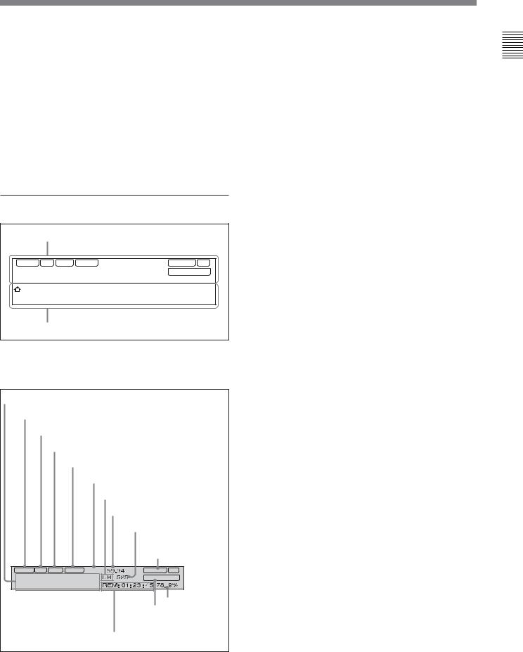
4 Time data/menu display section
1 Time data display
VIUB DF LTC VITC 2F |
59.94 |
|
CONFI ON |
|||||
01:23:45:06 |
REM: 01: 23 : 45 78. 9% |
|||||||
|
|
|
|
DB 525 |
DOLBY NR |
|||
1 |
|
|
|
|
|
|
|
|
VID. IN |
PB/EE |
CONFI |
CTL/TC |
MENU |
TCGSET |
|
||
|
Y-R,B |
PB |
OFF |
TC |
|
|
|
|
|
|
|
|
|
|
|
|
|
2 Menu display
2 Time data display
This displays indicators relating to time data and other indicators.
Time data display area 1 |
|
|
Time data type indicator |
||
DF indicator |
|
|
LTC indicator |
|
|
VITC indicator |
||
|
Capstan lock mode indicator |
|
|
|
Playback format indicator |
|
|
System frequency indicator |
|
|
525/625 indicator |
|
|
CONFI (ON)/PREREAD |
|
|
indicators |
VIUB DF LTC VITC |
2F |
CONFI ON |
01:23:45:06 |
DOLBY NR |
|
|
||
|
|
Speed indication area |
|
|
DOLBY NR indicator |
Time data display area 2 |
||
Time data display area 1
Normally this displays a CTL count, time code value, or user bit value according to the setting in function menu HOME page for F4 (CTL/TC).
Time data type indicator
This indicates the type of data displayed in the time data display area 1.
LTC (longitudinal time code): Time code recorded on a longitudinal track on the tape
LUB: LTC user bit values
VITC (vertical interval time code): Time code recorded in the vertical blanking interval
VIUB: VITC user bit value
DF (drop-frame) indicator (525-line mode only)
This lights when values of drop-frame mode time code are displayed.
LTC indicator
Regardless of the display in time data display
area 1, this indicator lights when LTC values are being read or recorded.
VITC indicator
Regardless of the display in time data display area 1, this indicator lights when VITC values are being read or recorded.
Capstan lock mode indicator
This indicates the capstan lock mode (2F, 4F, or 8F) set in function menu page 4 or in setup menu item 106.
Playback format indicator
This indicator shows the current playback format. DB: Digital Betacam format
IMX: MPEG IMX format, bit rate 50 Mbps, 8 audio channels/16 bits
IMX4: MPEG IMX format, bit rate 50 Mbps, 4 audio channels/24 bits
SX: Betacam SX format SP: Betacam SP format
No display: Betacam format
System frequency indicator
Displays the current playback field frequency.
525/625 indicator
This indicator shows the number of scan lines for the television standard (525 (NTSC) or 625 (PAL)) selected using setup menu item 013.
Parts of Function and Location 2 Chapter
Chapter 2 Location and Function of Parts |
2-7 |
Parts of Function and Location 2 Chapter
2-1 Control Panels
CONFI (ON)/PREREAD indicators
These indicate the state of the VTR CONFI playback 1) function. When the CONFI playback function is enabled by the setting in function menu HOME page, the CONFI indicator appears, and when CONFI playback is actually being carried out the ON indicator also appears.
When F6 (PREREAD) is set to ON in function menu page 4, the CONFI playback function is disabled and one of the following is displayed.
PREREAD: Preread of both audio and video A-PREAD: Preread of both audio only V-PREAD: Preread of video only
Time data display area 2
Displays data types and time data such as the time code of edit points and the total time of that tape. The following data types are shown.
TOTL: Time value representing the total tape length. REM: Time value representing the remaining tape
length.
Either TOTL or REM appears depending on the function menu page 3 setting for F5 (T INFO). The values displayed are approximate values
calculated on the basis of the detected tape diameter. They are not precise to units of seconds.
BOT: Returned to top of tape. EOT: Reached end of tape. IN: video IN point
OUT: video OUT point AIN: audio IN point AOUT: audio OUT point DUR: duration value
TCG (time code generator): time code generated by the internal time code generator
DOLBY NR indicator
This lights when the Dolby noise-reduction 2) circuit is functioning.
Speed indication area
This indicates the speed of a DMC playback.
During a DMC playback, “DMC SPD” is displayed in time data display area 2.
2 Menu display
This displays the function menu and setup menu.
For details on the function menu, see Chapter 11 and for details on the setup menu, see Chapter 12.
5 MULTI CONTROL knob and SHIFT indicator
In function menu operations, rotate the MULTI CONTROL knob to change settings that flash in the menu display section. In setup menu operations, rotate this knob to select menu items.
The SHIFT indicator lights when you press this knob in. In this state, the value of the setting changes by a greater amount when you rotate the knob.
6 RESET button
To reset a CTL, time code (TC) or user bit (UB) value displayed in time data display area 1, hold this button down.
Resetting the CTL value erases all edit points.
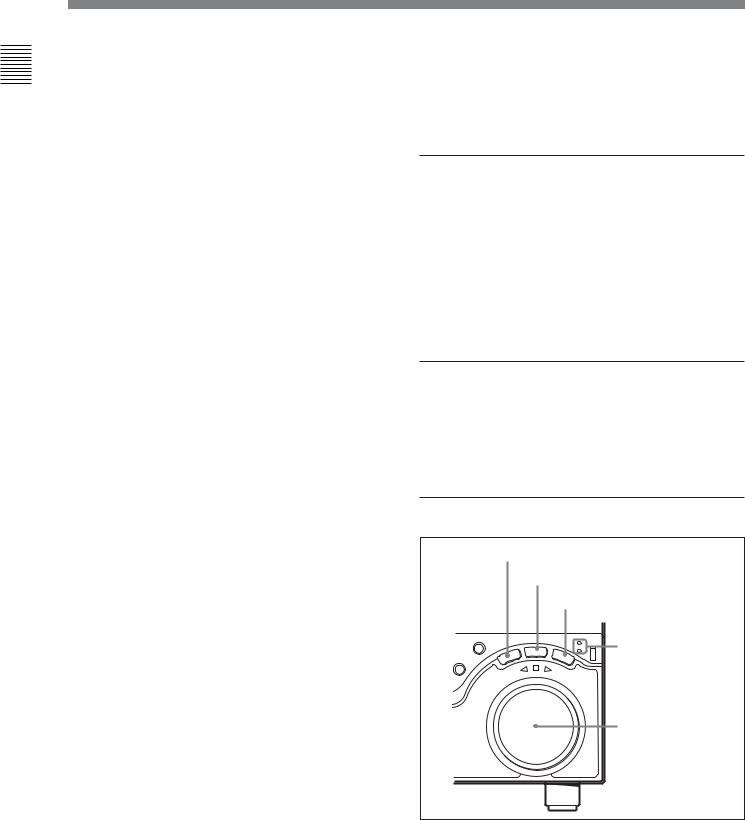
7Search control section
1 SHUTTLE button
2 JOG button
|
|
|
|
|
3 VAR button |
||
RECORDER |
|
|
|
|
SHUTTLE/VAR |
4 SHUTTLE/VAR |
|
|
|
|
|
JOG |
JOG |
||
|
|
|
LE |
VAR |
|
and JOG |
|
H |
|
|
|
||||
S |
|
TT |
|
|
|
||
|
U |
|
|
|
|
|
|
REVERSE |
|
FORWAR |
|
indicators |
|||
|
D |
|
|||||
5 Search dial
..........................................................................................................................................................................................................
1) CONFI playback: This refers to playback of the audio |
2) Dolby noise reduction: Dolby noise reduction |
and video signals immediately after recording, using the |
manufactured under license from Dolby Laboratories |
confidence heads, the signal being output to all intents |
Licensing Corporation. “DOLBY” and the double-D |
and purposes simultaneously with recording. This is used |
symbol ; are trademarks of Dolby Laboratories |
to check recording. |
Licensing Corporation. |
2-8 |
Chapter 2 Location and Function of Parts |

1 SHUTTLE button
To use the search dial for playback in shuttle mode, press this button, turning it on.
For details of playback in shuttle mode, see the description of the search dial 5.
2 JOG button
To use the search dial for playback in jog mode, press this button, turning it on.
For details of playback in jog mode, see the description of the search dial 5.
3 VAR (variable) button
To use the search dial for playback in variable speed mode, press this button, turning it on.
For details of playback in variable speed mode, see the description of the search dial 5.
4 SHUTTLE/VAR and JOG indicators
Either of the indicators is lit to show the current search mode or the mode used last. When the unit is turned on, the SHUTTLE/VAR indicator lights.
When the SHUTTLE/VAR indicator is lit: Shuttle or variable speed mode
When the JOG indicator is lit: Jog mode
5 Search dial
Turn this to carry out playback in the modes shown in the following table. Turning the dial clockwise lights the H indicator and plays back in the forward direction. Turning the dial counterclockwise lights the h indicator and plays back in the reverse direction. When the tape is stopped or the unit is turned on, the s indicator lights. Pressing the dial toggles between shuttle and jog modes or between variable speed and jog modes.
You can carry out noiseless playback in the following speed ranges depending on the tape format.
Digital Betacam: –1 to +3 times normal speed MPEG IMX: –1 to +3 times normal speed Betacam SX: –1 to +2 times normal speed Betacam/Betacam SP: –1 to +3 times normal speed
Playback modes using the search dial
Playback mode |
Operations and functions |
|
|
Shuttle |
Press the SHUTTLE button or the |
|
search dial so that the SHUTTLE |
|
button lights, then turn the search dial. |
|
Playback is carried out at a speed |
|
determined by the position of the |
|
search dial. The playback speed |
|
range is as follows: |
|
• Using a Digital Betacam tape: –50 to |
|
+50 times normal speed |
|
• Using an MPEG IMX tape: –78 to |
|
+78 times normal speed |
|
• Using a Betacam SX tape: –78 to |
|
+78 times normal speed |
|
• Using an analog Betacam tape: –35 |
|
to +35 times normal speed for 525/ |
|
60 mode or –42 to +42 times normal |
|
speed for 625/50 mode |
|
The search dial has detents at the still |
|
position and at ±5 times normal |
|
speed. |
|
The maximum shuttle mode playback |
|
speed can be changed by changing |
|
the setting of setup menu item 102 |
|
(see page 12-8). |
Jog |
Press the JOG button or the search |
|
dial so that the JOG button lights, then |
|
turn the search dial. Playback is |
|
carried out at a speed determined by |
|
the speed of rotation of the search |
|
dial. The playback speed range is –1 |
|
to +1 time normal speed. |
|
The search dial has no detents. |
|
|
Variable speed |
Press the VAR button, turning it on, |
|
then turn the search dial. You can |
|
control the playback speed finely (a |
|
maximum of 51 steps) in the range in |
|
which noiseless playback is possible. |
|
The search dial has detents at the still |
|
position and at the normal speed |
|
position. |
|
|
Capstan override |
For details on operation, see page |
|
4-9. |
Setting setup menu item 101 (see page 12-8) to KEY enables you to use only the SHUTTLE, JOG, and VAR buttons to select shuttle/jog/variable speed modes.
Parts of Function and Location 2 Chapter
Chapter 2 Location and Function of Parts |
2-9 |
Parts of Function and Location 2 Chapter
2-1 Control Panels
8 REC INHI (recording inhibit) indicator
This indicator is on or off according to the combination of the F5 (RECINH) setting on function menu page 4 and the record inhibit plug on the cassette, as shown in the following table. When this indicator is on, recording on tape is prohibited.
REC INHI indicator indications
RECINH setting |
State of the record |
REC INHI |
|
inhibit plug on the |
indicator state |
|
cassette |
|
ON |
Record inhibit/permit |
Lit |
|
|
|
OFF |
Record inhibit |
Lit a) |
|
Record permit |
Off |
|
|
|
a)It is possible to make a setting (setup menu item 107) so that in this case the indicator flashes.
9 Tape transport control section
1 PREROLL button |
|
||
|
2 REC button |
|
|
PREROLL |
REC |
EDIT |
3 EDIT button |
|
|
||
|
|
STANDBY |
|
|
|
|
4 STANDBY button |
REW |
PLAY |
F FWD |
STOP |
|
|
||
|
|
|
5 STOP button |
|
|
|
6 F FWD button |
|
7 PLAY button |
||
8 SERVO indicator
9 REW button
1 PREROLL button
Press this button to cue up to the preroll point (before the IN point by the time set as the preroll time) on the tape. You can change or select the preroll time and the state of the unit at the end of preroll (“stop mode” 1) or (still playback mode) using setup menu item 001 or 401.
Cuing up edit points
Hold down the IN, OUT, AUDIO IN, or AUDIO OUT button while pressing this button to cue up to the corresponding edit point.
2 REC (record) button
To start recording, press this button together with the PLAY button, turning it on.
Monitoring in E-E mode
When the unit is in stop mode, pressing the REC button causes it to light and allows you to monitor the video and audio in E-E mode. To return to the original state, press the STOP button.
During playback, search, fast forward, or rewind, while the REC button is held down you can monitor the video and audio in E-E mode. In this case the button does not light.
3 EDIT button
To carry out manual editing, press this button simultaneously with the PLAY button.
Monitoring in E-E mode
When the unit is in stop mode, pressing the EDIT button causes it to light and allows you to monitor the input signal selected with the ASSEMBLE button or INSERT buttons in E-E mode. To return to the original state, press the STOP button.
During playback, search, fast forward, or rewind, while the EDIT button is held down you can monitor the video and audio input signals in E-E mode.
4 STANDBY button
When a cassette is inserted and this button is off, to put the unit in standby mode, press the button, turning it on.
In standby mode, the drum is rotating and the tape is in contact with the drum. As a result, recording or playback can start immediately.
To end standby mode, press the STANDBY button, turning it off.
If 8 minutes (value can be varied using setup menu item 501) elapse in standby mode, the unit automatically switches out of standby mode to protect the tape.
..........................................................................................................................................................................................................
1)Stop mode: The state in which the device currently the subject of operation is stopped, and the STOP button is lit.
2-10 |
Chapter 2 Location and Function of Parts |

5 STOP button
To stop recording or playback, press this button, turning it on.
When you stop playback, the unit switches either to still playback or to E-E mode according to the setting on function menu HOME page for F2 (PB/EE) and the setting of setup menu item 108.
Fault display function
The STOP button flashes in the following cases related to reference signals:
•When F2 (OUTREF) is set to INPUT on function menu page 4, and there is no input video signal.
•When F2 (OUTREF) is set to REF in function menu page 4, and there is no external reference signal input or the input external reference signal is not synchronized to the input video signal.
6 F FWD (fast forward) button
To fast forward the tape, press this button, turning it on.
7 PLAY button
To start playback, press this button, turning it on.
1 ASSEMBLE button
Press this button, turning it on, to carry out assemble editing 1).
All signals (video signals, audio signals, time code signals, and so on) are recorded together.
Press the button again, turning it off, to exit from assemble editing mode.
Note
When even one of the INSERT buttons is lit, the ASSEMBLE button does not work. To use the ASSEMBLE button, turn off all the lit INSERT buttons.
2 INSERT buttons
Press the corresponding button, turning it on, to select a signal for insert editing 2). Press the button again, turning it off, to cancel the selection.
VIDEO button: Selects the video signal.
TC (time code) button: Selects time code.
CH1 to CH4 (audio channels 1 to 4) buttons:
Select the signals on audio channels 1 to 4. CUE button: Selects the cue audio signal.
Note
To operate in capstan override mode
Hold down this button, and turn the search dial.
For details of capstan override mode, see page 4-9.
8 SERVO indicator
Lights when the drum servo and capstan servo are locked.
9 REW (rewind) button
To rewind the tape, press this button, turning it on.
q; Editing mode setting section
1 ASSEMBLE button
ASSEMBLE |
|
|
INSERT |
|
|
VIDEO TC |
CH1 |
CH2 |
CH3 |
CH4 |
CUE |
2 INSERT buttons
When the ASSEMBLE button is lit, none of the INSERT buttons work. To use INSERT buttons, press the ASSEMBLE button, turning it off.
qa ALARM indicator and KEY INHI indicator
ALARM indicator
This lights when a hardware error is detected on the unit, and goes off when the error is resolved.
When this indicator is lit, an error message appears in the time data/menu display section. If you are using the SDI OUTPUT 3 (SUPER) or COMPOSITE VIDEO OUTPUT 3 (SUPER) connector, then when the setting of F4 (CHARA) in function menu page 4 is ON, the error message also appears on the monitor screen.
For details on error messages, refer to Section 1-24 in the Maintenance Manual Volume 1.
..........................................................................................................................................................................................................
1) Assemble editing: Editing in which new video/audio is |
2) Insert editing: Editing in which new video/audio is added |
added in sequence to the end of existing recorded video/ |
to an intermediate position of existing recorded video/ |
audio. |
audio. |
Parts of Function and Location 2 Chapter
Chapter 2 Location and Function of Parts |
2-11 |
Parts of Function and Location 2 Chapter
2-1 Control Panels
KEY INHI (inhibit) indicator
This indicator lights when the KEY INHIBIT switch on the switch panel (see page 2-14) is set to ON.
qs PLAYER button and RECORDER button
When you carry out editing using a VTR connected to the REMOTE 1-IN(9P) or REMOTE 1-OUT(9P) connector (see page 2-18) as the player and this unit as the recorder, these buttons select which VTR the editing control buttons and tape transport buttons on this unit control.
PLAYER: The editing control buttons and tape transport buttons on this unit control the external player VTR.
RECORDER: The editing control buttons and tape transport buttons on this unit control the recorder, that is to say, this unit.
When this unit is being used in standalone mode, neither button functions.
qd Editing control section
1 DMC EDIT button
2 MEMORY indicator
3 DELETE button
4 TRIM buttons
5 Edit point setting buttons
|
|
TRIM |
|
|
IN AUDIO OUT |
DMC EDIT |
DELETE |
ENTRY |
|
|
|
MEMORY |
|
|
PREVIEW |
AUTO EDIT |
REVIEW |
IN OUT
6 PREVIEW button
7 AUTO EDIT button
8 REVIEW button
1 DMC EDIT button
To carry out recording of playback at any speed between –1 and +3 times normal (between –1 and +2 times normal for Betacam SX), automatic playback, and automatic editing.
2 MEMORY indicator
When memorizing the playback speed using the DMC EDIT button, this indicator flashes as the playback speed is captured to memory, and lights continuously once the speed is captured.
3 DELETE button
This deletes an existing edit point.
Hold down this button and press the IN, OUT, AUDIO IN, or AUDIO OUT button which is lit, indicating an existing edit point, to delete the corresponding edit point. The button either goes off or flashes. When the button flashes, it is necessary to set the deleted edit point again.
To cancel the DMC mode, hold down the DMC EDIT button and press the DELETE button.
4 TRIM buttons
Use these buttons to trim an edit point to single-frame precision.
Hold down the IN, OUT, AUDIO IN, or AUDIO OUT button, and press one of these buttons. The ‘+’ button advances the corresponding edit point by one frame, and the ‘–’ button sets it back by one frame.
Pressing one of these buttons while holding down the PLAY button adjusts the tape speed by +8% or –8% correspondingly. (Capstan override function)
5 Edit point setting buttons
IN button and OUT button: To set a video IN point or OUT point, hold down the IN button or OUT button, and press the ENTRY button.
After you have made the setting, pressing the IN button or OUT button displays the video IN point or video OUT point set in time data display area 2.
AUDIO IN button and AUDIO OUT button: In insert editing, to set an audio IN point or audio OUT point separate from the corresponding video edit point, hold down the AUDIO IN button or AUDIO OUT button, and press the ENTRY button.
After you have made the setting, pressing the AUDIO IN button or AUDIO OUT button displays the audio IN point or audio OUT point set in time data display area 2.
2-12 |
Chapter 2 Location and Function of Parts |

ENTRY button: Use this for setting edit points and so on.
•To set a video IN point or OUT point: Hold down the IN button or OUT button, and press this button.
•To set an audio IN point or OUT point: Hold down the AUDIO IN button or AUDIO OUT button, and press this button.
6 REVIEW button
Use this button to review the editing results after carrying out automatic editing.
7 AUTO (automatic) EDIT button
After edit point setting, to carry out automatic editing (recording), press this button, turning it on.
If the IN point is not set, the automatic editing is carried out with the point where you pressed this button as the IN point.
If you pressed the PREVIEW button to carry out a preview, when the preview ends this button flashes.
8 PREVIEW button
After edit point setting, to preview the editing results on the monitor before recording, press this button, turning it on.
If the IN point is not set, the preview is carried out with the point where you pressed this button as the IN point.
During the preview it is lit, and when the preview ends it flashes.
qf Shot mark section
1 LIST button
LIST GOOD SHOT MARK |
2 REC/ERASE indicator |
|
|
REC/ |
3 MARK button |
ERASE |
3 MARK button
Hold this button down for 2 seconds or more, to enable writing, amending, and deleting of shot marks.
1 LIST button
Use this button to read in and list shot marks.
2 REC/ERASE indicator
This lights in the state in which writing, amending, and deleting of shot marks is enabled and flashes while a shot mark is actually being written, amended or deleted.
Parts of Function and Location 2 Chapter
Chapter 2 Location and Function of Parts |
2-13 |
Parts of Function and Location 2 Chapter
2-1 Control Panels
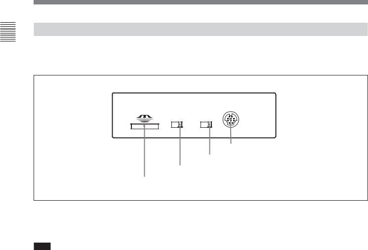
2-1-3 Switch Panel
To access the switch panel, open the lower control panel. On how to open the lower control panel, see the figure on page 2-1.
CONTROL PANEL
KEY INHI |
PANEL SEL |
ON OFF REAR FRONT
4 CONTROL PANEL connector
3 PANEL SELECT switch
2 KEY INHIBIT switch
1 Memory stick slot
1 Memory stick slot
Use this to update the firmware. You can also save or load setup menu settings onto the Memory Stick.
Note
After inserting a Memory Stick, allow at least five seconds to elapse before removing it.
For details on firmware update and save or load setup menu settings, see Section 13-1 “Overview of Setup Utility Menu Functions” and refer to the Maintenance Manual Volume 1.
2 KEY INHIBIT switch
Moving this switch to the ON position disables the controls on the upper and lower control panels.
You can specify which buttons and knobs are disabled in setup menu item 118.
3 PANEL SELECT switch
In addition to the lower control panel, you can connect a similar control panel to this unit. When two control panels are connected to the unit, the PANEL SELECT switch is used to specify which panel be enabled to control the unit.
FRONT: Enables the control panel connected to the CONTROL PANEL connector on the switch panel.
REAR: Enables the control panel connected to the CONTROL PANEL connector on the connector panel. When setup menu item 117 is set to PARA, this switch position also enables the control panel connected to the CONTROL PANEL connector on the switch panel.
4 CONTROL PANEL connector (10-pin, round type)
Plug in the lower control panel connection cable.
2-14 |
Chapter 2 Location and Function of Parts |
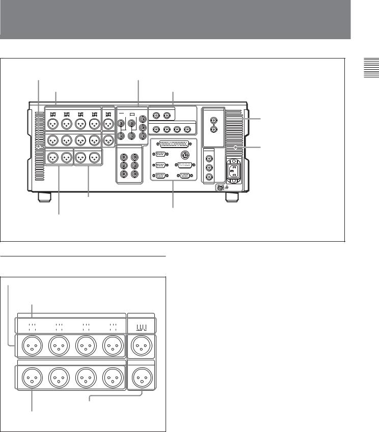
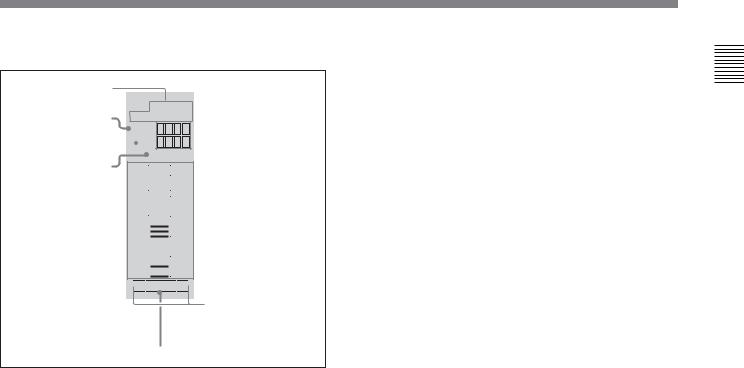
2-2 Connector Panel
Cooling fan |
2Analog video input/output section (see page 2-16) |
1Analog audio input/output |
3Digital audio input/output section (see page 2-16) |
section |
|


 75Ω
75Ω  75Ω
75Ω
7Time code input/output section (see page 2-18)
8Audio monitor signal output section
(see page 2-18)
4Digital signal input/ output section (see page 2-17)
Cooling fan
 5Power supply section
(see page 2-17)
6External device connectors (see page 2-17)
1 Analog audio input/output section
1 AUDIO INPUT CH1 to CH4 connectors
2AUDIO INPUT CH1 to CH4 and CUE IN LEVEL switches
AUDIO INPUT
CH1LEVEL |
|
|
CH2LEVEL |
|
|
CH3LEVEL |
|
|
CH4LEVEL |
|
|
|||||||||||||||||||||||
LOW |
|
|
|
|
|
HIGH |
LOW |
|
|
|
|
|
|
HIGH |
LOW |
|
|
|
|
|
|
HIGH |
LOW |
|
|
|
|
|
|
HIGH |
||||
OFF |
|
|
|
|
ON |
OFF |
|
|
|
|
|
ON |
OFF |
|
|
|
|
|
ON |
OFF |
|
|
|
|
|
ON |
||||||||
|
|
|
|
|
|
|
600Ω |
|
|
|
|
|
|
|
|
600Ω |
|
|
|
|
|
|
|
|
600Ω |
|
|
|
|
|
|
|
|
600Ω |
CUE
IN LEVEL
LOW

 HIGH
HIGH
OFF  ON 600Ω
|
|
AUDIO OUTPUT |
|
CUE |
CH1 |
CH2 |
CH3 |
CH4 |
OUT |
4CUE IN/OUT connectors
3AUDIO OUTPUT CH1 to CH4 connectors
1 AUDIO INPUT CH1 to CH4 (channels 1 to 4) connectors (XLR 3-pin, female)
Input analog audio signals to channels 1 to 4. You can record analog audio signals input to these connectors to any audio track on the tape.
2 AUDIO INPUT CH1 to CH4 (channels 1 to 4) and CUE IN LEVEL switches
Set these for each channel as shown in the following table, according to the audio/cue input level to the AUDIO INPUT CH1 to CH4 and CUE IN connectors and the impedance.
AUDIO INPUT CH1 to CH4 and
CUE IN LEVEL switch settings
Audio/cue input level and impedance |
Switch setting |
|
|
|
|
Level |
Impedance |
|
|
|
|
–60 dBu |
High impedance |
LOW-OFF |
(microphone input) |
(approx. 20 kΩ) |
(left position) |
+4 dBu |
High impedance |
HIGH-OFF |
(line audio input) |
(approx. 20 kΩ) |
(center position) |
+4 dBm |
600 Ω |
HIGH-ON 600 Ω |
(line audio input) |
|
(right position) |
|
|
|
3 AUDIO OUTPUT CH1 to CH4 (channels 1 to 4) connectors (XLR 3-pin, male)
These connectors output analog audio signals for channels 1 to 4.
4 CUE IN/OUT(cue audio input/output) connectors (XLR 3-pin, female/male)
The IN connector inputs and the OUT connector outputs the analog cue audio signals.
Parts of Function and Location 2 Chapter
Chapter 2 Location and Function of Parts |
2-15 |
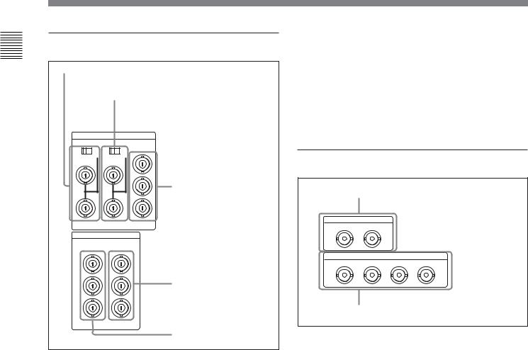
Parts of Function and Location 2 Chapter
2-2 Connector Panel
2 Analog video input/output section
1 REF.VIDEO INPUT connectors and 75 Ω termination switch
2COMPOSITE VIDEO INPUT connectors and 75 Ω termination switch
VIDEO INPUT
REF.VIDEO COMPOSITE COMPONENT
OFF |
ON OFF |
ON |
Y |
|
75 |
75 |
R-Y
3 COMPONENT VIDEO
INPUT connectors
B-Y
VIDEO OUTPUT
COMPOSITE COMPONENT
1Y
2R-Y
|
4 COMPONENT VIDEO |
3 |
OUTPUT connectors |
(SUPER) |
B-Y |
5 COMPOSITE VIDEO OUTPUT connectors
1 REF. (reference) VIDEO INPUT connectors (BNC type) and 75 Ω termination switch
Input a reference video signal. Input a video signal with chroma burst (VBS) or a monochrome video signal (VS). When using the loop-through connection set the switch to the OFF position, and otherwise to the ON position.
2 COMPOSITE VIDEO INPUT connectors (BNC type) and 75 Ω termination switch
Input analog composite video signals.
When using the loop-through connection set the switch to the OFF position, and otherwise to the ON position.
3 COMPONENT VIDEO INPUT connectors (BNC type)
Input analog component video signals (Y/R–Y/B–Y).
4 COMPONENT VIDEO OUTPUT connectors (BNC type)
These connectors output analog component video signals (Y/R–Y/B–Y).
5 COMPOSITE VIDEO OUTPUT connectors (BNC type)
These connectors output analog composite video signals.
When the setting of F4 (CHARA) in function menu page 4 is ON, connector 3 (SUPER) outputs a signal with superimposed time code, menu settings, alarm messages, and other text information.
3 Digital audio input/output section
1 AUDIO INPUT (AES/EBU) connectors
AUDIO INPUT(AES/EBU)
CH1/2 CH3/4
AUDIO OUTPUT(AES/EBU)
CH1/2 CH3/4 CH5/6 CH7/8
2 AUDIO OUTPUT (AES/EBU) connectors
1 AUDIO INPUT (AES/EBU) connectors (BNC type)
Input up to two sets (4 channels: channels 1/2 and 3/4) of AES/EBU format digital audio signals.
2 AUDIO OUTPUT (AES/EBU) connectors (BNC type)
These connectors output up to four sets (8 channels: channels 1/2, 3/4, 5/6 and 7/8) of AES/EBU format digital audio signals. Note that if your unit is a DVW2000/2000P, AES/EBU digital audio outputs are limited to two sets (4 channels: channels 1/2 and 3/4).
2-16 |
Chapter 2 Location and Function of Parts |
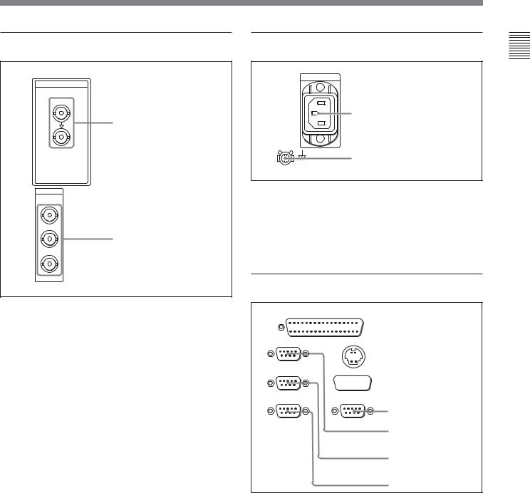
4 Digital signal input/output section |
5 Power supply section |
|
SDI |
|
|
INPUT |
|
|
|
1 AC IN connector |
|
1 SDI INPUT connectors |
|
|
|
2 Ground terminal |
|
SDI |
1 AC IN connector |
|
OUTPUT |
||
1 |
Use a power cord to connect this to an AC outlet. |
|
|
||
2 |
2 Ground terminal |
|
2 SDI OUTPUT connectors |
||
Connect this to ground. |
||
3(SUPER) |
||
|
||
|
6 External device connectors |
1 SDI (Serial Digital Interface) INPUT connectors (BNC type)
Input D1 format digital video/audio signals. Of the two connectors, the upper one is for input, and the lower one is for an active-through connection.
2 SDI (Serial Digital Interface) OUTPUT connectors (BNC type)
These connectors output D1 format digital video/audio signals.
When the setting of F4 (CHARA) in function menu page 4 is ON, connector 3 (SUPER) outputs a signal with superimposed time code, menu settings, alarm messages, and other text information.
REMOTE 2 PARALLEL I/O(50P)


 1 REMOTE 2 PARALLEL
I/O(50P) connector
REMOTE 1-IN(9P) CONTROL PANEL

 2 CONTROL PANEL connector
REMOTE 1-OUT(9P) VIDEO CONTROL


 3 VIDEO CONTROL connector
RS232C
4 OPTION connector
(OPTION)
5 REMOTE 1-IN(9P) connector
6 REMOTE 1-OUT(9P) connector
7 RS-232C connector
1 REMOTE 2 PARALLEL I/O(50P) connector (D-sub 50-pin)
Connect remote control signals from an external device.
For details, refer to the Installation Manual.
Parts of Function and Location 2 Chapter
Chapter 2 Location and Function of Parts |
2-17 |

Parts of Function and Location 2 Chapter
2-2 Connector Panel
2 CONTROL PANEL connector (round type, 10pin)
In addition to the lower control panel, a similar control panel can be connected to this unit. To connect such a second control panel, use this connector. When two control panels are connected, use the PANEL SELECT switch on the switch panel (see page 2-14) to specify which control panel will control this unit.
3 VIDEO CONTROL connector (D-sub 15-pin)
For remote control of the internal digital video processor, connect an optional BVR-50/50P Remote Control Unit.
Always power off this unit before connecting the remote control unit.
4 OPTION connector (D-sub 9-pin)
Not used.
5 REMOTE 1-IN(9P) connector (D-sub 9-pin)
When using this unit together with another DVWM2000/M2000P/2000/2000P or an MPEG IMX, D-1, D-2, or Betacam VTR, and a BVE-series BVE-900/ 910/2000/9000/9000P/9100/9100P or other editor, connect the optional 9-pin remote control cable from the other unit to this connector.
Depending on the setting of setup menu item 211, you can use this connector alone, or in a loop-through configuration with the REMOTE 1-OUT(9P) connector.
6 REMOTE 1-OUT(9P) connector (D-sub 9-pin)
This provides the loop-through output for remote control signals from the REMOTE 1-IN(9P) connector.
Depending on the setting of setup menu item 211, you can use this connector alone, or in a loop-through configuration with the REMOTE 1-IN(9P) connector.
7 RS-232C connector (D-sub 9-pin)
Use this for monitoring and diagnosis of the state of this unit from an external computer, using ISR (Interactive Status Reporting).
2-18 |
Chapter 2 Location and Function of Parts |
7 Time code input/output section
1 TIME CODE IN connector
TIME CODE
IN OUT
2 TIME CODE OUT connector
1 TIME CODE IN connector (XLR 3-pin, female)
To record time code from an external device, input a time code signal from the time code output connector of the other device.
2 TIME CODE OUT connector (XLR 3-pin, male)
This outputs a time code according to the operating state of the unit, as follows:
•During playback: the playback time code
By setting setup menu item 606, you can also output the time code from the internal time code generator locked to the playback time code.
•During recording: the time code generated by the internal time code generator or the time code input to the TIME CODE IN connector.
8 Audio monitor signal output section
1 MONITOR OUTPUT R
connector
MONITOR OUTPUT
RL
2 MONITOR OUTPUT L connector
1 MONITOR OUTPUT R connector (XLR 3-pin, male)
This outputs the audio signals whose output destination was set to ‘R’ with the audio signal selection buttons in the audio control section. If multiple tracks have been set to ‘R’, the signals of those tracks are mixed for output.
2 MONITOR OUTPUT L connector (XLR 3-pin, male)
This outputs the audio signals whose output destination was set to ‘L’ with the audio signal selection buttons in the audio control section. If multiple tracks have been set to ‘L’, the signals of those tracks are mixed for output.
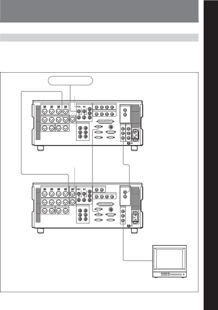
3-1 Connections to External Devices
3-1-1 Connections to Digital Devices
This unit can input serial digital signals (video and |
shows the connections with a MSW-A2000/A2000P/ |
audio) from another digital VTR such as the MSW- |
M2000/M2000P/2000/2000P unit as a player, with this |
A2000/A2000P/M2000/M2000P/2000/2000P and |
unit used as recorder. |
DVW-A500/A500P/500/500P. The following example |
|
Reference signal |
|
|
|
|
75 Ω termination |
|
|
|
|
switch: OFF |
|
|
|
|
REF. VIDEO INPUT |
|
|
|
|
|
REMOTE 1-IN(9P) |
|
|
|
MSW-A2000/A2000P/M2000/ |
|
SDI OUTPUT 3 |
|
|
M2000P/2000/2000P (player) |
|
|
|
|
75 Ω termination |
|
|
|
|
switch: ON |
|
|
|
|
REF. VIDEO INPUT |
REMOTE 1-OUT(9P) |
SDI INPUT |
|
|
75Ω |
75Ω |
|
|
|
|
SDI OUTPUT 3 |
|
|
|
DVW-M2000/M2000P/2000/2000P (recorder) |
|
|
|
|
|
|
BVM-1454 series video |
|
|
|
|
monitor |
|
|
|
|
Chapter 3 |
Preparations |
3-1 |
3 Chapter
PreparationsChapter
3
Preparations
Loading...