


 Loading...
DIGITAL CAMCORDER
DVW-970/970P
TM
OPERATION MANUAL [English] 1st Edition (Revised 1)

WARNING
To prevent fire or shock hazard, do not expose the unit to rain or moisture.
To avoid electrical shock, do not open the cabinet. Refer servicing to qualified personnel only.
For the customers in USA
This equipment has been tested and found to comply with the limits for a Class B digital device, pursuant to Part 15 of the FCC Rules. These limits are designed to provide reasonable protection against harmful interference in a residential installation. This equipment generates, uses, and can radiate radio frequency energy and, if not installed and used in accordance with the instructions, may cause harmful interference to radio communications. However, there is no guarantee that interference will not occur in a particular installation. If this equipment does cause harmful interference to radio or television reception, which can be determined by turning the equipment off and on, the user is encouraged to try to correct the interference by one or more of the following measures:
—Reorient or relocate the receiving antenna.
—Increase the separation between the equipment and receiver.
—Connect the equipment into an outlet on a circuit different from that to which the receiver is connected.
—Consult the dealer or an experienced radio/TV technician for help.
You are cautioned that any changes or modifications not expressly approved in this manual could void your authority to operate this equipment.
The shielded interface cable recommended in this manual must be used with this equipment in order to comply with the limits for a digital device pursuant to Subpart B of Part 15 of FCC Rules.
For the customers in the USA and Canada
•RECYCLING LITHIUM-ION BATTERIES
Lithium-Ion batteries are recyclable. You can help preserve our environment by returning your used rechargeable batteries to the collection and recycling location nearest you.
For more information regarding recycling of rechargeable batteries, call toll free 1-800-822-8837, or visit http://www.rbrc.org/
Caution: Do not handle damaged or leaking lithium-ion batteries.
For the customers in Europe
This product with the CE marking complies with the EMC Directive (89/336/EEC) issued by the Commission of the European Community.
Compliance with these directives implies conformity to the following European standards:
•EN55103-1: Electromagnetic Interference (Emission)
•EN55103-2: Electromagnetic Susceptibility (Immunity) This product is intended for use in the following Electromagnetic Environment(s):
E1 (residential), E2 (commercial and light industrial), E3 (urban outdoors) and E4 (controlled EMC environment, ex. TV studio).
Voor de Klanten in Nederland
Gooi de batterij niet weg maar lever deze in als klein chemisch afval (KCA).
For the customers in Taiwan only
2

Table of Contents
Chapter 1 Overview
1-1 |
Features............................................................................ |
8 |
|
|
1-1-1 Camera Features................................................................ |
8 |
|
|
1-1-2 |
VTR Features .................................................................... |
9 |
|
1-1-3 |
Other Features ................................................................... |
9 |
1-2 |
Example of System Configuration ............................... |
11 |
|
1-3 |
Precautions .................................................................... |
12 |
|
1-4 |
Using the CD-ROM Manual ........................................... |
12 |
|
|
1-4-1 |
Preparations..................................................................... |
12 |
|
1-4-2 |
Reading the CD-ROM Manual ....................................... |
12 |
Chapter 2 Locations and Functions of Parts and Controls
2-1 Power Supply ................................................................. |
14 |
|
2-2 Accessory Attachments................................................ |
15 |
|
2-3 Audio Functions ............................................................ |
16 |
|
2-4 Shooting and Recording/Playback Functions ............ |
19 |
|
2-5 Menu Operating Section ............................................... |
24 |
|
2-6 |
Time Code System......................................................... |
26 |
2-7 |
Warnings and Indications ............................................. |
28 |
2-8 |
Warnings and Indications on the Display Panel......... |
29 |
2-9 |
Indicators in the Viewfinder.......................................... |
31 |
Chapter 3 Recording and Playback
3-1 About Cassette .............................................................. |
32 |
|
3-1-1 Loading and Unloading a Cassette.................................. |
32 |
|
3-1-2 |
Preventing Accidental Erasure........................................ |
33 |
3-2 Recording ....................................................................... |
34 |
|
3-2-1 |
Basic Procedures ............................................................. |
34 |
3-2-2 Continuous Recording..................................................... |
35 |
|
3-2-3 Recording Essence Marks ............................................... |
36 |
|
3-2-4 |
Starting a Shoot with a Few Seconds of Pre-Stored Picture |
|
|
Data (Picture Cache Function: with CBK-MB01).......... |
39 |
3-2-5 |
Shooting Picture at Intervals (Interval Rec Function: with |
|
|
CBK-MB01) ................................................................... |
41 |
3-2-6 Continuous Recording on Previous Cut.......................... |
48 |
|
Table of Contents |
3 |
|
|

|
3-2-7 |
Searching for the Last Recorded Portion and Turning in |
|
|
|
Recording Pause Mode (End Search Function).............. |
49 |
3-3 |
Checking Recording and Playback ............................. |
50 |
|
|
3-3-1 |
Checking the Last Two Seconds of the Recording — |
|
|
|
Recording Review .......................................................... |
50 |
|
3-3-2 |
Checking the Recording on the Color Video Monitor — |
|
|
|
Playback in Color ........................................................... |
50 |
3-4 |
Freezing a Picture During Playback............................ |
51 |
|
3-5 |
Setting the Stand-by off Timer During Rec-Pause..... |
52 |
|
Chapter 4 Adjustments and Settings for Recording
4-1 Adjusting the Black Balance and the White Balance 53
|
4-1-1 |
Adjusting the Black Balance........................................... |
53 |
|
4-1-2 |
Adjusting the White Balance .......................................... |
54 |
4-2 |
Setting the Electronic Shutter ..................................... |
56 |
|
|
4-2-1 |
Shutter Modes ................................................................. |
56 |
|
4-2-2 |
Selecting the Shutter Mode and Shutter Speed............... |
57 |
4-3 |
Changing the Reference Value for Automatic Iris Ad- |
||
|
justment......................................................................... |
60 |
|
4-4 |
Adjusting the Audio Level............................................ |
62 |
|
|
4-4-1 Manually Adjusting the Audio Input Level of the AUDIO |
||
|
|
IN CH1/CH2 Connectors................................................ |
62 |
|
4-4-2 |
Manually Adjusting the Audio Level of the Front |
|
|
|
Microphone..................................................................... |
63 |
|
4-4-3 |
Input level of audio channels CH-3 and CH-4 ............... |
64 |
4-5 |
Setting the Time Data ................................................... |
64 |
|
|
4-5-1 |
Setting the Time Code .................................................... |
64 |
|
4-5-2 Saving the Actual Time in the Time Code ..................... |
65 |
|
|
4-5-3 |
Setting the User Bits ....................................................... |
65 |
|
4-5-4 Synchronizing the Time Code ........................................ |
66 |
|
Chapter 5 Menu Displays and Detailed Settings
5-1 |
Menu Organization and Operation .............................. |
68 |
|
|
5-1-1 Menu Organization ......................................................... |
68 |
|
|
5-1-2 |
Basic Menu Operations................................................... |
69 |
|
5-1-3 |
Editing the USER Menu ................................................. |
71 |
5-2 |
Status Display on the Viewfinder Screen ................... |
75 |
|
|
5-2-1 |
Layout of the Status Display on the Viewfinder Screen.75 |
|
|
5-2-2 |
Selecting the Display Items ............................................ |
77 |
4 |
Table of Contents |
|
|

5-2-3 Display Modes and Setting Change Confirmation/ |
|
|
|
Adjustment Progress Messages....................................... |
78 |
5-2-4 |
Setting the Marker Display ............................................. |
79 |
5-2-5 |
Setting the Viewfinder .................................................... |
79 |
5-2-6 Recording Shot Data Superimposed on the Color Bars.. |
80 |
|
5-2-7 |
Setting the Shot ID .......................................................... |
81 |
5-2-8 |
Displaying the Status Confirmation Windows................ |
82 |
5-2-9 |
Confirming the Image of the Return Video Signal in the |
|
|
Viewfinder ...................................................................... |
84 |
5-3 Adjustments and Settings from Menus ....................... |
85 |
|
5-3-1 |
Setting Gain Values for the GAIN Selector Positions .... |
85 |
5-3-2 |
Selecting the Output Signals ........................................... |
86 |
5-3-3 |
Setting the Color Temperature Manually........................ |
86 |
5-3-4 |
Specifying an Offset for the Auto White Balance |
|
|
Setting ............................................................................. |
87 |
5-3-5 |
Assigning Functions to Assignable Switches ................. |
88 |
5-3-6 |
Setting the Date/Time of the Internal Clock ................... |
90 |
5-3-7 |
Selecting the Lens File .................................................... |
91 |
5-3-8 |
Selecting the Aspect Ratio .............................................. |
91 |
5-3-9 Setting the CCD Scan Mode ........................................... |
92 |
|
5-3-10 Using UMID Data ......................................................... |
94 |
|
5-4 Resetting USER Menu Settings to the Standard Set- |
|
|
tings |
................................................................................ |
97 |
Chapter 6 Saving and Loading User Setting Data
6-1 |
Saving and Loading User Files .................................... |
98 |
|
|
6-1-1 Handling the “Memory Stick” ........................................ |
98 |
|
|
6-1-2 Saving USER Menu Data (User File) to the “Memory |
|
|
|
|
Stick”............................................................................... |
99 |
|
6-1-3 |
Loading Saved Data from a “Memory Stick” ............... |
101 |
6-2 |
Saving and Loading Scene Files................................ |
102 |
|
|
6-2-1 |
Saving a Scene File ....................................................... |
102 |
|
6-2-2 |
Loading a Scene File..................................................... |
104 |
|
6-2-3 |
Resetting the Settings of the Camcorder to the Standard |
|
|
|
Settings Saved in the Reference File ............................ |
106 |
6-3 |
Jumping to a File-Related Menu Page When Inserting a |
||
|
“Memory Stick”............................................................ |
106 |
|
Chapter 7 Setting Up the Camcorder
7-1 Power Supply ............................................................... |
108 |
Table of Contents |
5 |
|
|

7-1-1 |
Using a Battery Pack..................................................... |
108 |
7-1-2 |
Avoiding Breaks in Operation Due to an Exhausted |
|
|
Battery .......................................................................... |
108 |
7-1-3 Using an AC Adaptor ................................................... |
109 |
|
7-1-4 |
Using the Anton Bauer Ultralight System .................... |
109 |
7-2 Adjusting the Viewfinder............................................ |
110 |
|
7-2-1 |
Adjusting the Viewfinder Position ............................... |
110 |
7-2-2 |
Adjusting the Viewfinder Focus and Screen ................ |
110 |
7-2-3 |
Detaching the Viewfinder............................................. |
111 |
7-2-4 |
Detaching the Eyepiece ................................................ |
111 |
7-3 Mounting the Lens ...................................................... |
112 |
|
7-4 Adjusting the Flange Focal Length ........................... |
113 |
|
7-5 Audio Input System .................................................... |
113 |
|
7-5-1 |
Using the Supplied Microphone ................................... |
113 |
7-5-2 |
Using an External Microphone ..................................... |
114 |
7-5-3 |
Attaching a UHF Portable Tuner (for a UHF Wireless |
|
|
Microphone System)..................................................... |
115 |
7-5-4 Connecting Line Input Audio Equipment..................... |
117 |
|
7-6 Tripod Mounting.......................................................... |
117 |
|
7-7 Attaching/Detaching the Shoulder Strap.................. |
118 |
|
7-8 Adjusting the Shoulder Pad Position........................ |
119 |
|
7-9 Putting on the Rain Cover (Not Supplied) ................ |
119 |
|
7-10 Connecting the Remote Control Unit...................... |
120 |
|
Chapter 8 Maintenance
8-1 |
Testing the Camcorder Before Shooting.................. |
122 |
|
|
8-1-1 |
Preparations for Testing................................................ |
122 |
|
8-1-2 |
Testing the Camera ....................................................... |
122 |
|
8-1-3 Testing the VTR............................................................ |
124 |
|
8-2 |
Maintenance ................................................................ |
126 |
|
|
8-2-1 |
Cleaning the Video Heads ............................................ |
126 |
|
8-2-2 |
Cleaning the Viewfinder............................................... |
126 |
8-3 |
Operation Warnings.................................................... |
127 |
|
Appendixes
Specifications..................................................................... |
129 |
General .................................................................................... |
129 |
Video Camera Section............................................................. |
129 |
VTR Section ............................................................................ |
130 |
Recommended Additional Equipment .................................... |
130 |
6 |
Table of Contents |
|
|
Menu List ............................................................................. |
132 |
OPERATION Menu ................................................................ |
132 |
PAINT Menu ........................................................................... |
138 |
MAINTENANCE Menu.......................................................... |
143 |
FILE Menu............................................................................... |
152 |
DIAGNOSIS Menu.................................................................. |
154 |
About a “Memory Stick” .................................................... |
155 |
Index .................................................................................... |
157 |
Table of Contents |
7 |
|
|

Overview 1 Chapter
Overview
1-1 Features
The DVW-970/970P1) is a camcorder, in which a color video camera using 2/3-inch high-definition CCDs of a 16:9 aspect ratio and a recorder of the Digital BETACAM format are combined integrally. The camera’s CCDs have approximately 1,000,000 picture elements (pixels) (the number of effective pixels: approximately 500,000).
Its high imaging quality is established by the combination of Power HAD2) EX CCDs and advanced digital signal processing technologies. In addition to resistance to vibration, dust, and moisture of the Betacam-series camcorders, this unit has various functions that make it ideal as a tool for ENG3) and EFP4).
1)The DVW-970 is for the NTSC broadcast system. The DVW-970P is for the PAL broadcast system. The description given in this manual applies to both models, any differences being clearly noted in the text.
2)Abbreviation of “Power Hole-Accumulated Diode.” “Power HAD” is a registered trademark of Sony Corporation.
3)ENG: Electronic News Gathering
4)EFP: Electronic Field Production
1-1-1 Camera Features
2/3-inch Power HAD EX CCDs
The high sensitivity, low smear 2/3-inch Power HAD EX CCDs provide high image quality which is at the top of its class.
•The unit is switchable between a 16:9 aspect ratio wide image and 4:3 standard aspect ratio.
•You can select an interlaced scan mode or progressive scan mode (30 fps (frames per second)1) for the DVW970, 25 fps for the DVW-970P).
•With the optional CBK-FC01 Pull Down Board installed, a 24 fps2) progressive scan video can be recorded subjected to pull-down (24P mode), providing
imaging quality close to that of film (DVW-970 only).
1)More precisely, 29.97 fps
2)More precisely, 23.98 fps
Chapter 1
Camera signal processing for high quality video
•The 14-bit A/D converter provides stable high-quality images and reliability.
•The high-performance electronic shutter allows you to select extended clear scan mode (ECS1)) and high vertical resolution mode (EVS2)), to obtain clear, highquality video.
1)ECS: Extended Clear Scan
2)EVS: Super Enhanced Vertical Definition System
Shooting functions to cope with different shooting conditions
•A slow shutter function (up to 1/2 second) is provided as a standard feature. This allows noiseless shooting under very poor lighting conditions and a variety of expressive possibilities, such as shots of moving subjects which are smoothed out by afterimages.
•Owing to the scene file function, you can easily recall sets of adjustment values from the built-in memory, to match the particular lighting conditions.
•The ATW1) function provides automatic white balance adjustment in response to changing lighting conditions.
•The TruEyeTM 2) process yields distortion-free video, even with high intensity colors.
•The TURBO GAIN button enables an instantaneous boost of the video gain to the maximum 48 dB.
1)ATW: Auto Tracing White balance
2)TruEye: “TruEye” is a registered trademark of Sony Corporation.
Wide range of menu settings
The menus provide the following operations, among others:
•Status display, message, and marker display settings
•Camera adjustment settings
•Switch function assignment
•“Memory Stick” operations
You can also assign any settings to the USER menu, to create customized menus.
8 Features

Saving and recalling settings in a “Memory Stick”
Using an optional “Memory Stick” 1), you can save menu settings for particular shooting conditions, for recall as required.
1) “Memory Stick” is a trademark of Sony Corporation.
High-functionality viewfinder
The 2-inch monochrome viewfinder allows accurate focusing.
The switch settings, automatic black balance and white balance items, status, warnings and so on appear on the viewfinder screen.
Remote control connectors
By connecting an optional RM-B150/B750 or similar remote control unit, you can control the camera settings of this unit externally.
1-1-2 VTR Features
Digital BETACAM format
•Use of the Digital BETACAM format provides superior S/N, frequency range, waveform characteristics, and reproducibility of details for high quality video and audio.
•A long recording time of approximately 40 minutes for the DVW-970 and 48 minutes for the DVW-970P is achieved.
Metadata for easier and more comfortable operation
It is possible to record recording-start markers and goodshot markers on the tape while shooting, and search automatically for required cuts when editing.
Time Code operations inevitable in broadcasting
•LTC1) and VITC2) recording and LTC playback can be performed.
•The built-in time code generator can be synchronized with an external generator.
•A lithium battery is the back-up power supply for the built-in time code generator enabling the time code to be held for approximately 5 years without being charged (with the camcorder power supply).
•The time code can be displayed in the LCD window screen even when the power is off. The automatic power shut-off function allows you to set the time when the time code display disappears.
1)LTC: Longitudinal Time Code
2)VITC: Vertical Interval Time Code
Audio functions
•A slot-in UHF portable tuner WRR-855A/855B (not supplied) can be attached.
•Four channels of 20-bit digital audio can be recorded, as well as four channels of 16-bit digital audio.
•When an audio cable is connected to the AUDIO IN CH- 1/CH-2 connectors (XLR 3-pin), the audio signals input to the XLR 3-pin connectors are recorded regardless of the AUDIO IN switch setting. This function is called the XLR connection automatic detection function.
•The AUDIO OUT connector (XLR 5-pin) allows the camcorder to output signals as stereo audio.
Other VTR functions
•Recording continuity from the very next frame is ensured.
•It is possible to automatically rewind and review the last 2 seconds of the recording on the tape for a quick check immediately after shooting.
•A 4-times-normal speed search function provides quick positioning of the tape.
•The camcorder searches for the most recently recorded cut and records the new cut over it. This function is called the RE-TAKE function.
•The camcorder searches for the point most recently recorded on the tape and automatically switches to paused recording mode (REC pause). This function is called the End Search function.
1-1-3 Other Features
Proper balancing design
A new shoulder-pad system that enables position adjustment in the front-to-rear direction with no need to use a tool ensures proper balance when using the unit.
Instant operation assignable switches
Function-assignable switches are provided on the side panel. Assigning the functions most useful to you, by selecting them on the menu pages, will create a smooth shooting environment.
Function extension interface and optional boards
•An extension connector can be attached to the battery attachment on the rear panel, to allow various camera adapters to be fitted.
•Use of the following optional boards permits you to expand the functions.
Overview 1 Chapter
Features 9

Overview 1 Chapter
CBK-MB01 Picture Cache Board:
Installing the board allows the camcorder to record up to several seconds of the picture before the REC button is pressed (Picture Cache Function) and to shoot pictures at intervals (Interval Rec).
CBK-FC01 Pull Down (24P) Board (for the DVW970 only):
With the board installed, a 24 fps progressive scan video can be recorded subjected to 2-3 pull-down.
CBK-SD01 SDI Output Board:
Installing the board enables SDI signal output from the VIDEO OUT connectors.
10 Features
1-2 Example of System Configuration
The diagram below shows a typical configuration of the |
For more information about the fittings, connections, or |
camcorder for ENG and EFP. |
use of additional equipment and accessories, see “Chapter |
|
7 Setting Up the Camcorder” as well as the operation |
|
manuals for the connected equipment. |
Viewfinder-related equipment
Name / Purpose |
Magnification |
Part No. |
Fog-proof filter |
— |
1-547-341-11 |
|
|
|
Lens assembly |
–2.8 D to +2.0 D |
A-8262-537-A |
|
|
|
Lens assembly |
–3.6 D to –0.8 D |
A-8262-538-A |
|
|
|
Lens assembly |
–3.6 D to +0.4 D |
A-8267-737-A |
|
|
|
Lens assembly |
–2.4 D to +0.5 D |
A-8314-798-A |
(3 × magnification) |
|
|
|
|
|
BKW-401 Viewfinder Rotation Bracket
Audio input signals
External microphone ECM-672 or similar microphone
CAC-12 Microphone Holder
Analog audio equipment
CCXA-53 audio cable
WRR-860/862 UHF Portable Tuner
WRR-855-series UHF Synthesized Tuner Unit
Control signals
RM-B150/B750 Remote Control Unit
“Memory Stick” (see page 155)
AC power supply
Product |
Model name |
AC Adaptor |
AC-550/550CE |
|
|
AC Adaptor |
AC-DN10 |
|
|
Battery |
|
|
|
Product |
Model name |
Battery Charger |
BC-M150/M50 |
|
|
Battery Pack |
BP-GL65/GL95/L60S |
|
|
Wireless video/audio transmission
Wireless Camera WLL-CA50
Transmitter
Extension board
Product |
Model name |
Pull Down (24P) Board |
CBK-FC01 1) |
SDI Output Board |
CBK-SD01 |
|
|
Picture Cache Board |
CBK-MB01 |
|
|
1) For the DVW-970 only
Audio output
XLR 5-pin connector for stereo microphone (service part)
Video output
Video monitor for color image check during shooting
Overview 1 Chapter
Example of System Configuration |
11 |
|
|

Overview 1 Chapter
1-3 Precautions
Use and Storage
Do not subject the unit to severe shocks
The internal mechanism may be damaged or the body warped.
After use
Always turn off the power.
Before storing the unit for a long period
Remove the battery pack.
Use and storage locations
Store in a level, ventilated place. Avoid using or storing the unit in the following places.
•Places subject to temperature extremes
•Very damp places
•Places subject to severe vibration
•Near strong magnetic fields
•In direct sunlight or close to heaters for extended periods
To prevent electromagnetic interference from portable communications devices
The use of portable telephones and other communications devices near this unit can result in malfunctions and interference with audio and video signals.
It is recommended that the portable communications devices near this unit be powered off.
Note on laser beams
Laser beams may damage the CCDs. If you shoot a scene that includes a laser beam, be careful not to let the laser beam be directed into the lens of the camera.
Use at a high temperature
If the unit is used at a high temperature, white flecks may appear on the screen.
1-4 Using the CD-ROM
Manual
The supplied CD-ROM includes versions of the Operation Manual for the DVW-970/970P in English, Japanese, French, German, Italian, Spanish, and Chinese in PDF format.
1-4-1 Preparations
The following program must be installed on your computer in order to read the operation manuals contained on the CD-ROM.
• Adobe Reader Version 6.0 or higher
Memo
If Adobe Reader is not installed, you can download it from the following URL:
http://www.adobe.com/
Adobe and Adobe Reader are trademarks of Adobe Systems Incorporated in the United States and/or other countries.
1-4-2 Reading the CD-ROM Manual
To read the operation manual contained on the CD-ROM, do the following:
1 Insert the CD-ROM in your CD-ROM drive.
A cover page appears automatically in your browser. If it does not appear automatically in the browser, double-click on the index.htm file on the CD-ROM.
2 Select and click on the operation manual that you want to read.
This opens the PDF file of the operation manual.
Memo
The files may not be displayed properly, depending on the version of Adobe Reader. In such a case, install the latest version you can download from the URL mentioned in “1- 4-1 Preparations” above.
Notes
•If you have lost or damaged the CD-ROM, you can purchase a new one to replace it. Contact your Sony service representative.
•You can purchase a printed version of the operation manual (English version). Contact your Sony service representative.
12 Precautions / Using the CD-ROM Manual

When ordering, be sure to specify the part number of the manual you want.
Part No. |
Models covered |
|
|
3-869-913-0X DVW-970/970P
Overview 1 Chapter
Using the CD-ROM Manual 13

Locations and Functions |
Chapter 2 |
of Parts and Controls |
Controls and Parts of Functions and Locations 2 Chapter
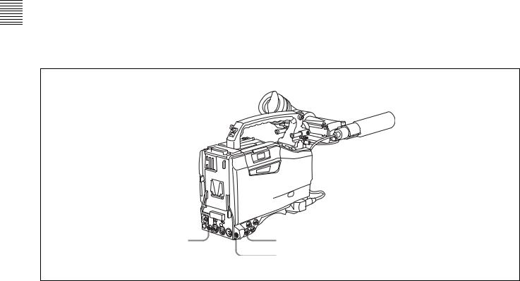
2-1 Power Supply
 aBattery attachment


 bDC IN connector
cPOWER switch
dLIGHT switch
a Battery attachment
Attach a battery pack, BP-GL65, BP-GL95, or BP-L60S. Furthermore, by attaching an AC-DN10 AC Adaptor, you can operate the camcorder from AC power.
b DC IN connector (XLR type, 4-pin, male)
To operate the camcorder using an AC power supply, connect an AC-550/550CE AC Adaptor with the DC output cable supplied with the adaptor.
To use an external battery, connect its DC output cable to the DC IN connector.
c POWER switch
This switch turns the main power supply on and off.
d LIGHT switch
This determines how a video light connected to the LIGHT connector is turned on and off.
AUTO: When the switch on the video light is in the on position, putting the camcorder in recording mode turns the video light on automatically. When using the
auto interval recording mode, the video light is automatically turned on immediately before recording starts.
MANUAL: You can turn the video light on or off manually, using its own switch.
14 Power Supply
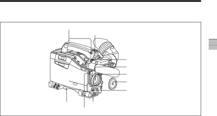
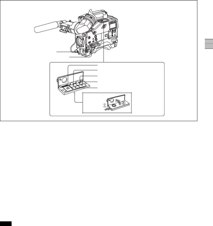
2-2 Accessory Attachments
aShoulder strap posts
bLight shoe
cLIGHT connector
dLens mount
eLens locking lever
fLens mount cap
gLENS connector
iShoulder pad |
hTripod mount |
Lens cable clamp
a Shoulder strap posts
Attach the supplied shoulder strap to these posts.
For details, see “7-7 Attaching/Detaching the Shoulder Strap” on page 118.
b Light shoe
Attach an optional accessory such as a video light to this shoe.
c LIGHT connector (2-pin, female)
Connect the cable of an Anton Bauer Ultralight System attached to the light shoe. The system operates with lights powered by 12 V, with a maximum power consumption of 50 W.
d Lens mount (special bayonet mount)
Use this for mounting the lens.
e Lens locking lever
After inserting the lens in the lens mount, rotate the lens mount ring with this lever to lock the lens in position.
f Lens mount cap
Remove this cap by pushing up the lens locking lever. When no lens is mounted, keep this cap fitted for protection from dust.
g LENS connector (12-pin)
Fit the lens cable to this connector. Contact your Sony representative for more information about the lens you can use.
h Tripod mount
When using the camcorder on a tripod, attach the tripod adaptor (optional).
i Shoulder pad
You can move the shoulder pad forwards or backwards by raising up the shoulder pad locking lever. Do this to ensure the best balance when shooting with the camcorder on your shoulder.
For details, see “7-8 Adjusting the Shoulder Pad Position” on page 119.
Controls and Parts of Functions and Locations 2 Chapter
Accessory Attachments |
15 |
|
|
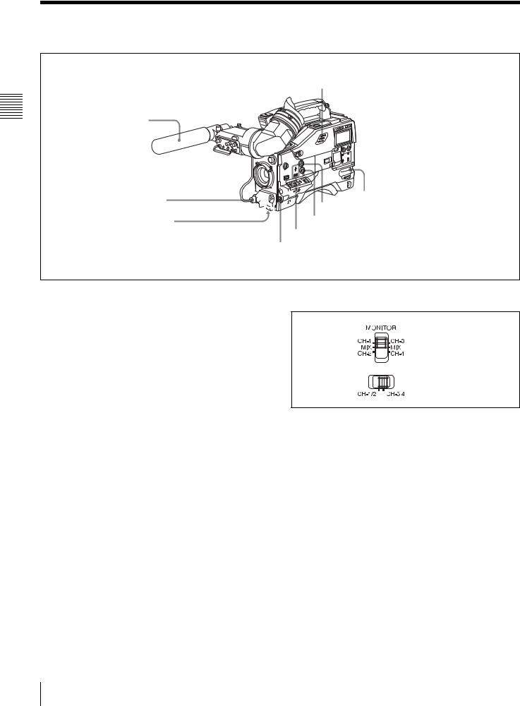
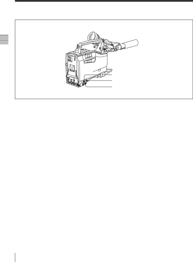
2-3 Audio Functions
Controls and Parts of Functions and Locations 2 Chapter
hBuilt-in speaker
aMicrophone
bMIC IN connector
cMIC LEVEL control


 dEARPHONE jack (rear)
 gALARM volume control
fMONITOR volume control
eMONITOR switch and CH-1/2 / CH-3/4 switch dEARPHONE jack (front)
Audio functions (1)
a Microphone
This is a super-cardioid directional monaural microphone with an external power supply (+48 V) system.
b MIC IN (microphone input) connector (XLR type,
3-pin, female)
Connect the supplied microphone to this connector. A microphone other than the supplied one may also be connected as long as it can operate with the power (+48 V) supplied from this connector.
By fitting a 5-pin connector (service part number: A-1053- 453-A), you can also use a stereo microphone.
c MIC (microphone) LEVEL control
This control adjusts the audio level of the microphone connected to the MIC IN connector.
d EARPHONE jacks (minijacks)
You can monitor the E-E sound 1) during recording and playback sound during playback. Plugging an earphone into the jack automatically cuts off the built-in speaker.
When an alarm is indicated, you can hear the alarm sound through the earphone.
1)E-E: Abbreviation of “Electric-to-Electric.” In E-E mode, video and audio signals input to the camcorder are output after passing through internal electric circuits only. This can be used to check input signals.
MONITOR switch
CH-1/2 / CH-3/4 switch
MONITOR switch and CH-1/2 / CH-3/4 switch
CH-1/2 / CH-3/4 switch:
This determines the pair of audio channels selected with the MONITOR switch.
CH-1/2 position: channels 1 and 2 CH-3/4 position: channels 3 and 4
The signals output from the AUDIO OUT connector and EARPHONE jacks and the audio level meter in the display window also depend on the setting of this switch.
MONITOR switch:
This selects the audio monitor channels output to the earphone or speaker, depending on the setting of the CH- 1/2 / CH-3/4 switch.
e MONITOR switch and CH-1/2 / CH-3/4 switch
These switches together determine the channel selection for audio monitor output.
16 Audio Functions

CH-1/2/CH-3/4 |
MONITOR |
Audio output |
switch |
switch |
|
position |
position |
|
CH-1/2 |
CH-1 |
Audio channel 1 |
|
|
|
|
MIX |
Mix sound of channels 1 and 2 |
|
|
|
|
CH-2 |
Audio channel 2 |
|
|
|
CH-3/4 |
CH-3 |
Audio channel 3 |
|
|
|
|
MIX |
Mix sound of channels 3 and 4 |
|
|
|
|
CH-4 |
Audio channel 4 |
|
|
|
g ALARM volume control
This control adjusts the speaker or earphone alarm volume. At the minimum position, no sound can be heard.
Minimum Maximum
ALARM volume control
f MONITOR volume control
This control adjusts the speaker or earphone volume for sounds other than the alarm sound. At the minimum position, no sound can be heard.
h Built-in speaker
The speaker can be used to monitor E-E sound during recording, and playback sound during playback. The speaker also sounds alarms to reinforce visual warnings. If you connect an earphone to the EARPHONE jack, the speaker is automatically muted.
See “8-3 Operation Warnings” on page 127 for information about alarms.
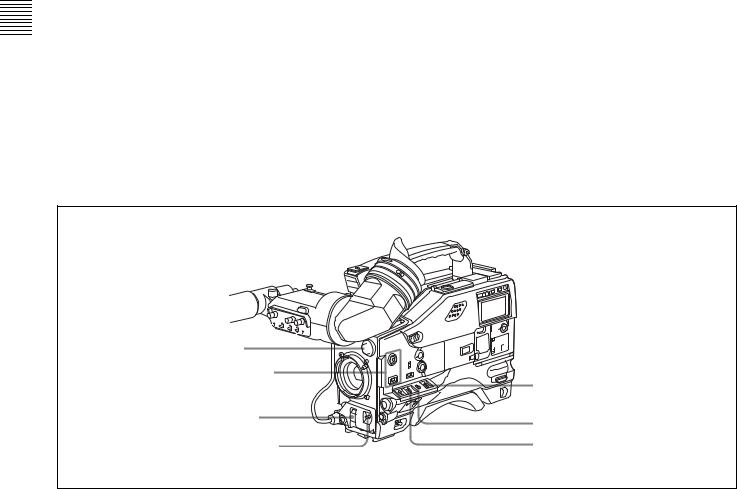
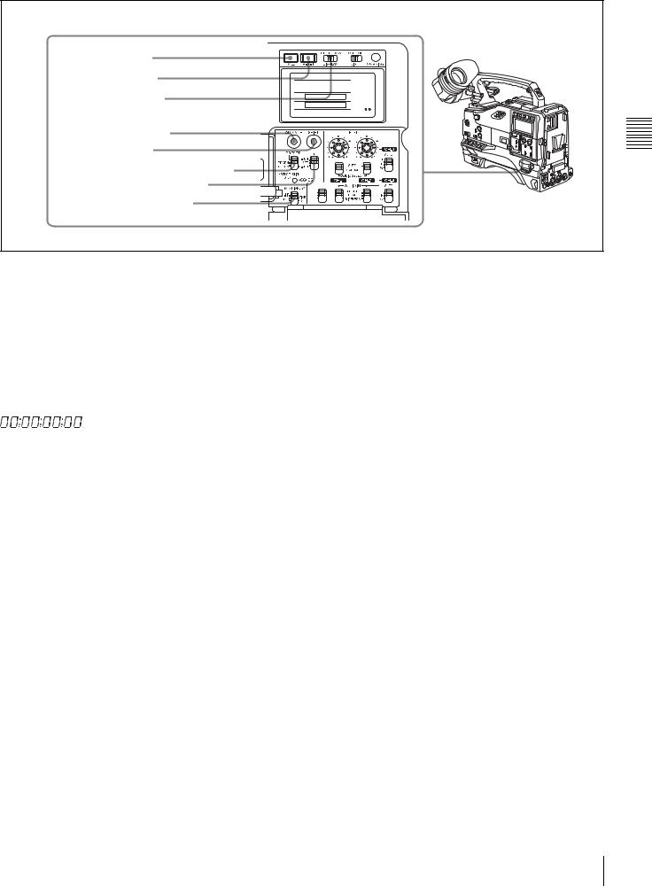
|
iLEVEL (CH-1/CH-2) controls |
|
jAUDIO SELECT CH-1/CH-2 switches |
CUE IN |
kAUDIO IN CH-1/CH-2/CH-3/CH-4 switches |
MIX |
CH-1

CH-2
lCUE IN switch
mAUDIO OUT connector
nAUDIO IN CH1/CH2 connectors and LINE/MIC/+48V ON switches
oDC OUT 12V connector
Audio functions (2)
i LEVEL (CH-1/CH-2) (audio channel-1 and |
j AUDIO SELECT CH-1/CH-2 (audio channel-1 and |
channel-2 recording level) controls |
channel-2 adjustment method selection) switches |
These controls adjust the audio levels of channels 1 and 2 |
These switches select the audio level adjustment method |
when the AUDIO SELECT switches are set to MANUAL. |
for each of audio channels 1 and 2. |
|
AUTO: Select this setting for automatic adjustment. |
|
MANUAL: Select this setting for manual adjustment. |
Controls and Parts of Functions and Locations 2 Chapter
Audio Functions 17

Controls and Parts of Functions and Locations 2 Chapter
k AUDIO IN CH-1/CH-2/CH-3/CH-4 (audio input selection) switches
CH-1/CH-2 switches
These switches select the audio input signals to be recorded on audio channels 1 and 2.
FRONT: The input signal source is the microphone connected to the MIC IN connector.
REAR: The input signal source is the audio equipment connected to the AUDIO IN CH1/CH2 connectors.
WIRELESS: The input signal source is a WRR-855A/ 855B UHF Synthesized Tuner Unit (option).
CH-3/CH-4 switches
These switches select the audio input signals to be recorded on audio channels 3 and 4.
F (front): The input signal source is the microphone connected to the MIC IN connector.
R (rear): The input signal source is the audio equipment connected to the AUDIO IN CH1/CH2 connectors.
W (wireless): The input signal source is a WRR-855A/ 855B UHF Synthesized Tuner Unit (not supplied).
l CUE IN (cue track input) switch
This switch selects the input signal to be recorded on the cue track.
CH-1: Signal selected by the AUDIO IN CH-1 switch MIX: Mixed signals selected by the AUDIO IN CH-1 and
CH-2 switches
CH-2: Signal selected by the AUDIO IN CH-2 switch
m AUDIO OUT (audio output) connector (XLR type,
5-pin, male)
This connector outputs the audio signals recorded on audio channels 1 and 2 or audio channels 3 and 4.
The MONITOR CH-1/2 / CH-3/4 switches allow you to select the audio signal to be monitored.
n AUDIO IN CH1/CH2 (audio channel-1 and channel-2 input) connectors (XLR type, 3-pin, female) and LINE/MIC/+48 V ON (line input/microphone input/external power supply +48V ON) switches
These are audio input connectors for channels 1 and 2 to which you can connect audio equipment or a microphone. The LINE/MIC/+48V ON switches select the audio source of the audio input signals connected to each of these connectors.
LINE: Line input audio equipment
MIC: Microphone with an internal power supply +48V ON: Microphone with an external power supply
system
o DC OUT 12 V (DC power output) connector (4-pin, female)
This connector supplies power for a WRR-860A/862A/ 862B UHF Portable Tuner (option). Do not connect any equipment other than the UHF portable tuner.
18 Audio Functions
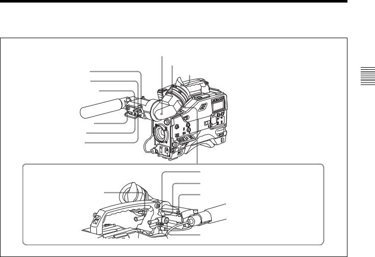
2-4 Shooting and Recording/Playback Functions |
|
|
gViewfinder |
|
hDiopter adjustment ring |
aTALLY indicator |
Eyecup |
bBRIGHT control |
|
cCONTRAST control |
|
dPEAKING control |
|
eZEBRA switch |
|
fTALLY switch |
|
|
jViewfinder left-right positioning ring |
iViewfinderfront-rear |
kCamera operator tally indicator |
|
|
positioning lever |
lViewfinder stopper |
|
mLOCK knob |
Shooting and recording/playback functions (1)
a TALLY indicator
Setting the TALLY switch to HIGH or LOW enables this indicator. The indicator lights during recording on the VTR. Like the REC indicator in the viewfinder, it flashes to indicate a problem. You can set the indicator brightness with the TALLY switch.
b BRIGHT (brightness) control
This control adjusts the picture brightness on the viewfinder screen. It has no effect on the camera output signal.
c CONTRAST control
This control adjusts the picture contrast on the viewfinder screen. It has no effect on the camera output signal.
d PEAKING control
This control adjusts the sharpness of the picture on the viewfinder screen to make focusing easier. It has no effect on the camera output signal.
e ZEBRA switch
This switch controls the zebra pattern1) on the viewfinder screen.
ON: The zebra pattern is displayed and stays. OFF: No zebra pattern is displayed.
MOMENT: The zebra pattern is displayed and stays for 5 to 6 seconds.
The zebra pattern is factory set to indicate picture areas where the video level is approximately 70%.You can use the setup menu to change the setting so that areas where the video level is 100% and above are also displayed at the same time.
1)The zebra pattern aids in manual iris adjustment by indicating areas of the picture where the video level is approximately 70% and 100% and above.
For information about how to change the zebra pattern setting in the setup menu, see “5-2-5 Setting the Viewfinder” on page 79.
f TALLY switch
This switch controls the TALLY indicator, setting its brightness (HIGH or LOW) or turning it off. HIGH: The TALLY indicator brightness is high. OFF: The TALLY indicator is disabled.
LOW: The TALLY indicator brightness is low.
Controls and Parts of Functions and Locations 2 Chapter
Shooting and Recording/Playback Functions |
19 |
|
|
Controls and Parts of Functions and Locations 2 Chapter
g Viewfinder
The viewfinder lets you view the image in black and white while shooting, recording or playing back. It also displays various warnings and messages related to the settings or operating conditions of the camcorder, a zebra pattern, safety zone marker 1), and center marker 2).
1)The safety zone marker is a rectangle indicating the effective picture area.
2)The center marker indicates the center of the picture with a crosshair.
For details, see “5-2-4 Setting the Marker Display” on page 79.
h Diopter adjustment ring
Use this ring to adjust the viewfinder image for your vision.
i Viewfinder front-rear positioning lever
To adjust the viewfinder position in the front-rear direction, loosen this lever and the LOCK knob. After adjustment, retighten this lever and the LOCK knob.
j Viewfinder left-right positioning ring
Loosen this ring to move the viewfinder sideways.
k Camera operator tally indicator
This indicator lights while the camcorder is recording. Slide the window open when you shoot with your eye away from the viewfinder. This indicator flashes when the battery level is running low or the disc is almost full.
l Viewfinder stopper
Pull up this stopper to detach the viewfinder from the camera.
m LOCK knob
To adjust the viewfinder position in the front-rear direction, loosen this knob and the viewfinder front-rear positioning lever. After adjustment, retighten this knob and the viewfinder front-rear positioning lever.


 uTURBO GAIN button nFILTER selector


oASSIGN 1/2 switches
tWHITE BAL switch
pSHUTTER selector |
sOUTPUT/DCC selector |
|
qAUTO W/B BAL switch rGAIN selector
Shooting and recording/playback functions (2)
n FILTER selector
Use this selector to select the most appropriate filter to match the light source illuminating the subject.
When this selector is used with the display mode set to 3, the new setting appears on the viewfinder screen for about 3 seconds. (e.g.: ND: 1, CC: B)
The relationships between the selector settings and filter selections as well as examples of filters for different shooting conditions are as follows:
FILTER selector (outer knob) setting |
CC filter selection |
A |
Cross filter 1) |
B |
3200K |
|
|
C |
4300K |
|
|
D |
6300K |
|
|
1)A type of special effect filter, which generates a cross of light on a highlighted portion.
FILTER selector (inner knob) setting |
ND filter selection |
1 |
Clear |
|
|
2 |
1/4 ND |
3 |
1/16 ND |
4 |
1/64 ND |
20 |
Shooting and Recording/Playback Functions |
|
|
Shooting condition |
CC filter |
ND filter |
|
Sunrise and sunset; inside |
B (3200K) |
1 |
(clear) |
studio |
|
|
|
|
|
|
|
Clear skies |
C (4300K) or |
2 |
(1/4 ND) or |
|
D (6300K) |
3 |
(1/16 ND) |
Cloudy or raining |
D (6300K) |
1 (clear) or |
|
|
|
2 |
(1/4 ND) |
Very bright conditions such |
C (4300K) or |
3 |
(1/16 ND) or |
as snow, at high altitudes, |
D (6300K) |
4 |
(1/64 ND) |
or at the seashore |
|
|
|
o ASSIGN 1/2 switches
You can assign the desired functions to each of the ASSIGN 1 switch (push button) and ASSIGN 2 switch (sliding) on the FUNCTION 1 page of the USER menu.
For details, see “5-3-5 Assigning Functions to Assignable Switches” on page 88.
p SHUTTER selector
Set this selector to ON to use the electronic shutter. Push it down to SELECT to switch the shutter speed or mode setting within the range previously set with the setup menu.
When this selector is operated, the new setting appears on the setting change/adjustment progress message display area for about 3 seconds.
For details about the shutter speed and mode settings, see “4-2 Setting the Electronic Shutter” on page 56.
q AUTO W/B BAL (automatic white/black balance adjustment) switch
This switch activates the white balance and black balance automatic adjustment functions.
WHT: Automatic adjustment of the white balance. If the WHITE BAL switch is set to A or B, the white balance setting is stored in the corresponding memory. The memory stores a separate white balance setting for each filter setting.
BLK: Automatic adjustment of the black set and black balance.
r GAIN selector
This selector switches the gain of the video amplifier to match the lighting conditions during shooting. The gains corresponding to the L, M, and H settings can be selected from the setup menu. The factory settings are L = 0 dB, M = 9 dB, and H = 18 dB.
When this selector is adjusted, the new setting appears on the setting change/adjustment progress message display area of the viewfinder screen for about 3 seconds.
For details about setting the gain values, see “5-3-1 Setting Gain Values for the GAIN Selector Positions” on page 85.
s OUTPUT/DCC (output signal/dynamic contrast control) selector
This selector switches the video signal that is output to the VTR, viewfinder, and video monitor, between the following two.
BARS: Outputs the color bar signal.
CAM: Outputs the video signal from the camera. When this is selected, you can switch DCC1) on and off with this selector.
1)DCC (Dynamic Contrast Control)
Against a very bright background with the iris opening adjusted to the subject, objects in the background will be lost in the glare. The DCC function will suppress the high intensity and restore much of the lost detail and is particularly effective in the following cases.
•Shooting people in the shade on a sunny day
•Shooting a subject indoors, against a background through a window •Any high contrast scene
BARS, DCC OFF
A color bar signal is output and the DCC circuit does not operate. For example, use the setting for the following purposes.
•Adjusting the video monitor
•Recording the color bar signal
CAM, DCC OFF
The video signal from the camera is output, and the DCC circuit does not operate.
CAM, DCC ON
The video signal from the camera is output, and the DCC circuit operates.
OUTPUT/DCC selector
t WHITE BAL (white balance memory) switch
This switch controls the white balance setting. PRST (preset): Adjusts the color temperature
corresponding to the position of the FILTER selector. Use the PRST setting when you have no time to adjust the white balance.
A or B: When the AUTO W/B BAL switch is pushed to WHT, the white balance is automatically adjusted according to the current position of the FILTER selector, and the adjusted value is stored in either memory A or memory B. (There are two memories for each filter, allowing a total of eight adjustments to be stored.) When this switch is set to A or B, the camcorder automatically adjusts itself to the stored value corresponding to the current settings of this switch and the FILTER selector.
You can use the AUTO W/B BAL switch even when ATW1) is in use.
1)ATW (Auto Tracing White Balance)
The white balance of the picture being shot is adjusted automatically for varying lighting conditions.
Controls and Parts of Functions and Locations 2 Chapter
Shooting and Recording/Playback Functions |
21 |
|
|
Controls and Parts of Functions and Locations 2 Chapter
B (ATW): When this switch is set to B and on the FUNCTION 2 page of the OPERATION menu, “WHITE B CH” is set to “ATW”, ATW is activated.
When this switch is adjusted, the new setting appears on the setting change/adjustment progress message display area of the viewfinder screen for about 3 seconds.
You can assign the ATW ON/OFF function to the ASSIGN 1 switch (push button) on the FUNCTION 1 page of the USER menu.
For details, see “5-3-5 Assigning Functions to Assignable Switches” on page 88.
u TURBO GAIN button
When shooting under extremely poor lighting conditions, press the button once to boost the video gain to the value preset on the GAIN SW page of the USER menu (up to 48 dB). To stop boosting the gain, press the button once more.
vVIDEO OUT connector |
wTEST OUT connector |
|
xREMOTE connector |
Shooting and recording/playback functions (3)
v VIDEO OUT connector (BNC type)
This connector outputs a composite video signal (standard level, 75-ohm terminated) for a video monitor. With a video monitor connected to this connector, you can monitor the picture being shot by the camera or the picture played back by the VTR. To choose between the composite video signal output and SDI signal output, use the menu. When synchronizing the time code of an external VTR with that of the camcorder, connect this connector to the GENLOCK IN connector of the external VTR.
By installing the CBK-SD01 extension board (not supplied), you can output an SDI signal (supporting embedded audio and the EDH function) from this connector.
For details on how to select the output signal, see “5-3-2 Selecting the Output Signals” on page 86.
w TEST OUT connector (BNC type)
This connector outputs the video signal (standard level, 75ohm terminated) for a video monitor. The output signal can be selected from composite or RGB. The factory setting is
composite, and the setting returns to composite whenever the unit is powered on.
Depending on menu settings, menus, time code, and shot data can be superimposed on the image on the monitor.
For details on how to select the test output signal, refer to the Maintenance Manual.
x REMOTE connector (8-pin)
Connect the RM-B150/B750 Remote Control Unit, which makes it possible to control the VTR and camera remotely.
22 |
Shooting and Recording/Playback Functions |
|
|
yVTR START button
zVTR SAVE/STBY connector
wj EJECT button
wk REW button and indicator wl F FWD button and indicator e; PLAY button and indicator ea STOP button
Shooting and recording/playback functions (4)
Controls and Parts of Functions and Locations 2 Chapter
y VTR START button
Press this button to start recording. Press it again to stop recording. The effect is exactly the same as that of the VTR button on the lens.
When the REC SWITCH function is assigned to the ASSIGN 1 switch (push button), you can use the switch as the REC START button.
z VTR SAVE/STBY (standby) switch
This switch controls the VTR power mode during pauses in recording.
SAVE: Power saving mode. When you press the VTR START button, there is a short delay before recording starts, but power consumption in this mode is less than in standby mode, so that battery life is extended. When the switch is set to SAVE, the SAVE indicator in the viewfinder lights.
STBY: Standby mode. Recording starts as soon as you press the REC START button.
Notes
•Avoid allowing the camcorder to remain in STBY (standby) mode for a long time.
•Even if the switch is set to the STBY position, the camcorder can automatically turn to power saving mode if the tape does not run for a certain period. In such a case, the VTR SAVE indicator in the viewfinder lights. This function is effective when a setting other than OFF is selected for the STBY OFF TIMER item on the VTR
MODE page of the MAINTENANCE menu. The STBY OFF TIMER item also allows you to select the length of time until the camcorder turns to power saving mode.
For detailed information, see “3-5 Setting the Stand-by off Timer During Rec-Pause” on page 52.
wj EJECT button
Press this button to eject or load a cassette.
wk REW (rewind) button and indicator
Press this button to rewind the tape. The indicator lights during rewinding.
wl F FWD (fast forward) button and indicator
Press this button to fast forward the tape. The indicator lights during fast forward.
e; PLAY button and indicator
Press this button to view the recorded picture in the viewfinder or on the color video monitor. The indicator lights during playback.
The 4 times normal speed search function is provided to make it far quicker to find a desired location of the tape. Press the REW button or F FWD button during playback to view the 4 times normal speed search picture.
ea STOP button
Press this button to stop the tape.
Shooting and Recording/Playback Functions |
23 |
|
|

Controls and Parts of Functions and Locations 2 Chapter
2-5 Menu Operating Section
a“Memory Stick” compartment |
cSTATUS ON/SEL / OFF switch |
dMENU ON/OFF switch |
eCANCEL/PRST / ESCAPE switch |
Cover |
bMENU knob |
Menu operation section
a “Memory Stick” compartment
ACCESS indicator
MEMORY STICK OPEN button
f
“Memory Stick” Eject button
Open the cover of the “Memory Stick” compartment by pressing the MEMORY STICK OPEN button and insert the “Memory Stick.”
To remove, press the eject button.
During data writing/loading to/from the “Memory Stick,” the ACCESS indicator lights or flashes.
For details, see “6-1-1 Handling the “Memory Stick”” on page 98.
b MENU knob
Use this knob to change the page selection or a setting within the menu.
Press: If you press this knob when the arrow (b) is placed at the page title on the menu, the arrow changes to a question mark (?) and you can change the page by turning this knob.
When the arrow mark is placed at a position other than the page title, you can change the setting of the current item by pressing and turning this knob.
Turn: Turn this knob to change the page or change item settings.
c STATUS ON/SEL / OFF (menu display on/page selection/display off) switch
To enable this switch, set the MENU ON/OFF switch to OFF.
Closing the cover automatically sets the MENU ON/OFF switch to OFF.
ON/SEL: Each time this switch is pushed upward, a window to confirm the menu settings and status of the camcorder appears on the viewfinder screen. The window consists of three pages, which are switched each time the switch is pushed upward. Each page is displayed for about 10 seconds.
OFF: To clear the page immediately after display, push this switch down to the OFF position.
You can select the pages to be displayed on the menu.
For details, see “5-2-8 Displaying the Status Confirmation Windows” on page 82.
d MENU ON/OFF switch
To use this switch, open the cover.
24 |
Menu Operating Section |
|
|

This switch is used to display the menu on the viewfinder screen or the test signal screen.
Closing the cover automatically sets this switch to OFF. ON: Displays the menu on the viewfinder screen or the test
signal screen, at the last accessed page. When the menu is used for the first time, the first page is displayed.
OFF: Removes the menu from the viewfinder screen or the test signal screen.
e CANCEL/PRST (preset) / ESCAPE switch
To enable this switch, set the MENU ON/OFF switch to ON.
Closing the cover automatically sets the MENU ON/OFF switch to OFF.
CANCEL/PRST: Pushing this switch up to this position displays the message to confirm whether the previous settings are cancelled or settings are reset to their initial values, depending on the menu operating condition.
Pushing this switch up to this position again cancels the previous settings or resets the settings to their initial values.
ESCAPE: Use this switch when the menu page, which has a hierarchical structure, is opened. Each time the switch is pushed to this position, the page returns to one stage higher in the hierarchy.
Controls and Parts of Functions and Locations 2 Chapter
Menu Operating Section 25
2-6 Time Code System
Controls and Parts of Functions and Locations 2 Chapter
aGENLOCK IN connector
bTC IN connector
cTC OUT connector
Time code functions (1)
a GENLOCK IN connector (BNC type)
•This connector accepts a reference signal when the camera is to be genlocked or when the time code is to be synchronized with external equipment. Use the items GL H PHASE, GL SC PHASE and GL SC 0/180 SEL on the GENLOCK page of the MAINTENANCE menu to adjust the genlock H-phase (phase of horizontal sync signal) and the sub-carrier phase.
•This connector also accepts a return video signal.
You can display the return video signal in the viewfinder screen while holding the RET button down with “RETURN VIDEO” set to “ON” on the GENLOCK page of the OPERATION menu.
b TC IN (time code input) connector (BNC type)
To synchronize the time code of this unit to an external time code, input the reference time code to this connector.
c TC OUT (time code output) connector (BNC type)
To synchronize the time code of an external VTR to that of the camcorder, connect this connector to the reference time code input connector of the external VTR.
26 Time Code System
dHOLD button |
|
eRESET button |
|
fDISPLAY switch |
|
gADVANCE button |
|
hSHIFT button |
|
iPRESET/REGEN/CLOCK switch |
|
jF-RUN/SET/R-RUN switch |
CUE IN |
|
CH-1 |
kDATA DISPLAY switch |
MIX |
CH-2 |
|
|
Time code functions (2)
d HOLD (display hold) button
Pressing this button instantly freezes the time data displayed in the counter display section. (The time code generator continues running.) Pressing this button again releases the hold. You can use this button, for example, to determine the exact time of a particular shot.
When the HOLD button is activated, the time data is displayed in the following format:
PRESET: Records time code with a preset initial value. REGEN: Records time code continuous with the existing time code recorded on the tape. Regardless of the
setting of the F-RUN/SET/R-RUN switch, the camcorder operates in R-RUN mode.
CLOCK: Records time code synchronized to the internal clock. Regardless of the setting of the F-RUN/SET/R- RUN switch, the camcorder operates in F-RUN mode.
Controls and Parts of Functions and Locations 2 Chapter
For details of the counter display, see “2-8 Warnings and Indications on the Display Panel” on page 29.
e RESET button
Pressing this button resets the time data displayed on the counter display section to “00:00:00:00” or the user bit data to “00000000.”
f DISPLAY (LCD display) switch CTL: Control signal
TC: Time code
DATA: The item selected by the DATA DISPLAY switch.
For details, see “Time code display” on page 30.
g ADVANCE button
For setting the time code, user bits, or real time, each press of this button increments the flashing digit selected by the SHIFT button.
h SHIFT button
For setting the time code, user bits, or real time, this button selects the digit to be changed. The selected digit flashes.
i PRESET/REGEN (regeneration)/CLOCK switch
This switch selects whether to set a new time code or to follow the already recorded time code.
For more information, see “To make the time code consecutive” on page 65.
j F-RUN/SET/R-RUN (free run/set/recording run) switch
This switch selects the operating mode for the internal time code generator.
F-RUN: Time code keeps advancing, regardless of the operating state of the VTR. Use this setting when aligning the time code with real time or when synchronizing the time code with an external time code.
SET: Set the switch to this position to set the time code or user bits.
R-RUN: The time code value advances only during recording. Use this setting to have a consecutive time code on the tape.
For details, see “4-5-1 Setting the Time Code” on page 64 and “4-5-3 Setting the User Bits” on page 65.
k DATA DISPLAY switch U-BIT: To display the user bit value
SHOT-TIME: To display the date and time from the shot data
SHOT-NO: Not used
Time Code System 27
Controls and Parts of Functions and Locations 2 Chapter
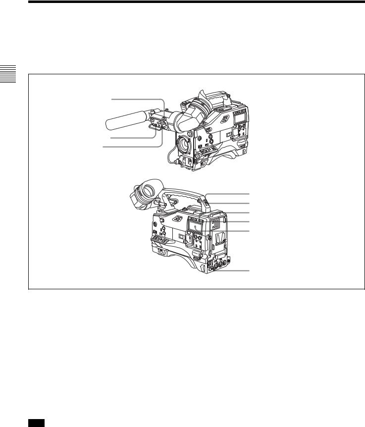
2-7 Warnings and Indications
Besides the viewfinder, speaker and earphones, the indicators and displays described in this section also provide you with information such as the operating state of the camcorder and warnings.
aTALLY indicator
bDISPLAY switch
cTALLY switch
dBACK TALLY indicator eBACK TALLY switch fLIGHT switch
gWARNING indicator hDisplay panel
iREAR TALLY indicator
Warning and indication functions
a TALLY indicator
Setting the TALLY switch on the viewfinder to HIGH or LOW enables this indicator. It lights when the VTR starts recording. Like the REC indicator in the viewfinder, it also flashes to provide warnings. The brightness of this indicator when it is lit can be switched with the TALLY switch.
b DISPLAY switch
This switches the indications on the viewfinder screen on or off.
ON: The indications appear on the viewfinder screen. OFF: The indications do not appear on the viewfinder
screen.
Note
Setting the MENU ON/OFF switch to ON displays the menu on the viewfinder screen even if the DISPLAY switch is set to OFF.
c TALLY switch
This switch controls the TALLY indicator as follows: HIGH: The TALLY indicator brightness is high. OFF: The TALLY indicator is disabled.
LOW: The TALLY indicator brightness is low.
d BACK TALLY indicator
When the BACK TALLY switch is set to ON, this indicator has the same function as the TALLY indicator.
e BACK TALLY switch
This switch enables or disables the BACK TALLY and REAR TALLY indicators.
ON: The BACK TALLY and REAR TALLY indicators are enabled.
OFF: The BACK TALLY and REAR TALLY indicators are disabled.
f LIGHT switch
This switch turns on/off the display panel light.
28 |
Warnings and Indications |
|
|
g WARNING indicator
This indicator lights up or flashes when there is a fault in the VTR.
For details, see “8-3 Operation Warnings” on page 127.
h Display panel
This displays VTR-related warnings, battery status, tape status, audio levels, time data, and so on.
For details, see “2-8 Warnings and Indications on the Display Panel” on page 29.
i REAR TALLY indicator
When the BACK TALLY switch is set to ON, this indicator has the same function as the TALLY indicator.
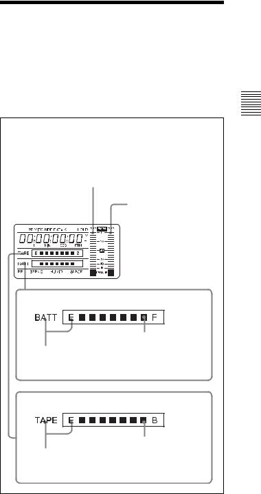
2-8 Warnings and Indications on the Display Panel
Tape status, battery status and audio level
Audio channel level meter:
When the CH-1/2 / CH-3/4 switch is set to CH-1/2, the audio channel level 1 is displayed.
When the CH-1/2 / CH-3/4 switch is set to CH-3/4, the audio channel level 3 is displayed.
Audio channel level meter:
When the CH-1/2 / CH-3/4 switch is set to CH-1/2, the audio channel level 2 is displayed.
When the CH-1/2 / CH-3/4 switch is set to CH-3/4, the audio channel level 4 is displayed.
Battery status indicator
Fully charged
Nearly dead: “BATT” flashes.
Dead battery (battery must be charged): “BATT” and “E” flash.
Tape status indicator
Full (at beginning)
Close to end: “TAPE” flashes.
End (tape must be replaced): “TAPE” and “E” flash.
Tape status, battery status, and level indicators
Controls and Parts of Functions and Locations 2 Chapter
Warnings and Indications on the Display Panel |
29 |
|
|
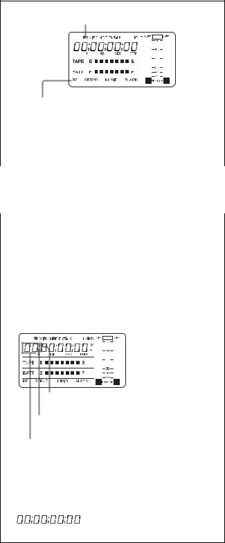
VTR operation status and status indicators
Lights during playback
|
|
|
|
|
|
|
|
|
|
|
|
|
|
|
|
|
|
|
|
|
|
|
|
|
|
|
|
|
|
|
|
|
|
|
|
|
|
|
|
|
|
|
|
|
|
|
|
|
|
|
|
|
|
|
|
|
|
|
|
|
|
|
|
|
|
|
|
|
|
|
|
|
|
|
|
|
|
|
|
|
|
|
|
|
|
|
|
|
|
|
|
|
|
|
|
|
|
|
|
|
|
|
|
|
|
|
|
|
|
|
|
|
|
|
|
|
|
|
|
|
|
|
|
|
|
|
|
|
|
|
|
|
|
|
|
|
|
|
|
|
|
|
|
|
|
|
|
|
|
|
|
|
|
|
|
|
|
|
|
|
|
|
|
|
|
|
|
|
|
|
|
|
|
|
|
|
|
|
|
|
|
|
|
|
|
|
|
|
|
|
|
|
|
|
|
|
|
|
|
|
|
|
|
|
|
|
|
|
|
|
|
|
|
|
|
|
|
|
|
|
|
|
|
|
|
|
|
|
|
|
|
|
|
|
|
|
|
|
|
|
|
|
|
|
|
|
|
|
|
|
|
|
|
|
|
|
|
|
|
|
|
|
|
|
|
|
|
|
|
|
|
|
|
|
|
|
|
|
|
|
|
|
|
|
|
|
|
|
|
|
|
|
|
|
|
|
|
|
|
|
|
|
|
|
|
|
|
|
|
|
|
|
|
|
|
|
|
|
|
|
|
|
|
|
|
|
|
|
|
|
|
|
|
|
|
|
|
|
|
|
|
|
|
|
|
|
|
|
|
|
|
|
|
|
|
|
|
|
|
|
|
|
|
|
|
|
|
|
|
|
|
|
|
|
|
|
|
|
|
|
|
|
|
|
|
|
|
|
|
|
|
|
|
|
|
|
|
|
|
|
|
|
|
|
|
|
|
|
|
|
|
|
|
|
|
|
|
|
|
|
|
|
|
|
|
|
|
|
|
|
|
|
|
|
Warning indication |
||||||||||||||||||||||||||||||||
|
|
|
|||||||||||||||||||||||||||||||||
|
|
|
|||||||||||||||||||||||||||||||||
|
|
|
|||||||||||||||||||||||||||||||||
Chapter |
|
||||||||||||||||||||||||||||||||||
|
RF: Lights if the recording heads are clogged. |
||||||||||||||||||||||||||||||||||
|
|
|
SERVO: Lights if the servo motor fails. |
||||||||||||||||||||||||||||||||
2 |
|
|
HUMID: Lights if condensation is on the drum. |
||||||||||||||||||||||||||||||||
|
|
SLACK: Lights if the tape is not winding properly. |
|||||||||||||||||||||||||||||||||
Locations |
|
||||||||||||||||||||||||||||||||||
|
For details, see “8-3 Operation Warnings” on page 127. |
||||||||||||||||||||||||||||||||||
|
|
|
|||||||||||||||||||||||||||||||||
and |
|
|
|
|
|
|
|
|
|
|
|
|
|
|
|
|
|
|
|
|
|
|
|
|
|
|
|
|
|
|
|
|
|
||
|
|
|
|
|
VTR operation and status indicators |
||||||||||||||||||||||||||||||
ofFunctions |
|
|
|
|
|
||||||||||||||||||||||||||||||
Time code display |
|||||||||||||||||||||||||||||||||||
|
|
||||||||||||||||||||||||||||||||||
andParts |
|
|
|
|
|
|
|
|
|
|
|
|
|
|
|
|
|
|
|
|
|
|
|
|
|
|
|
|
|
|
|
|
|
||
|
Lights in playback mode. |
||||||||||||||||||||||||||||||||||
|
|
|
|||||||||||||||||||||||||||||||||
Controls |
|
|
|
Lights when VITC is selected for the time code. |
|||||||||||||||||||||||||||||||
|
|
|
|||||||||||||||||||||||||||||||||
|
|
|
|
|
|||||||||||||||||||||||||||||||
|
|
|
|
|
|
|
|
Lights in non-drop frame mode. (DVW-970 only) |
|||||||||||||||||||||||||||
|
|
|
|
|
|
|
|
||||||||||||||||||||||||||||
|
|
|
|
|
|
|
|
|
|
Lights when the camcorder is synchronized |
|||||||||||||||||||||||||
|
|
|
|
|
|
|
|
|
|
with an external time code. |
|||||||||||||||||||||||||
|
|
|
|
|
|
|
|
|
|
|
|
|
Lights when the time code generator |
||||||||||||||||||||||
|
|
|
|
|
|
|
|
|
|
|
|
|
|||||||||||||||||||||||
|
|
|
|
|
|
|
|
|
|
|
|
|
is on hold. |
||||||||||||||||||||||
|
|
|
|
|
|
|
|
|
|
|
|
|
|
|
|
|
|
|
|
|
|
|
|
|
|
|
|
|
|
|
|
|
|
|
|
|
|
|
|
|
|
|
|
|
|
|
|
|
|
|
|
|
|
|
|
|
|
|
|
|
|
|
|
|
|
|
|
|
|
|
|
|
|
|
|
|
|
|
|
|
|
|
|
|
|
|
|
|
|
|
|
|
|
|
|
|
|
|
|
|
|
|
|
|
|
|
|
|
|
|
|
|
|
|
|
|
|
|
|
|
|
|
|
|
|
|
|
|
|
|
|
|
|
|
|
|
|
|
|
|
|
|
|
|
|
|
|
|
|
|
|
|
|
|
|
|
|
|
|
|
|
|
|
|
|
|
|
|
|
|
|
|
|
|
|
|
|
|
|
|
|
|
|
|
|
|
|
|
|
|
|
|
|
|
|
|
|
|
|
|
|
|
|
|
|
|
|
|
|
|
|
|
|
|
|
|
|
|
|
|
|
|
|
|
|
|
|
|
|
|
|
|
|
|
|
|
|
|
|
|
|
|
|
|
|
|
|
|
|
|
|
|
|
|
|
|
|
|
|
|
|
|
|
|
|
|
|
|
|
|
|
|
|
|
|
|
|
|
|
|
|
|
|
|
|
|
|
|
|
|
|
|
|
|
|
|
|
|
|
|
|
|
|
|
|
|
|
|
|
|
|
|
|
|
|
|
|
|
|
|
|
|
|
|
|
|
|
|
|
|
|
|
|
|
|
|
|
|
|
|
|
|
|
|
|
|
|
|
|
|
|
|
|
|
|
|
|
|
|
|
|
|
|
|
|
|
|
|
|
|
|
|
|
|
|
|
|
|
|
|
|
|
|
|
|
|
|
|
|
|
|
|
|
|
|
Lights when the time code, CTL or real time is displayed.
Lights when the HOLD button is pressed.1)
Time counter display: Shows the time code,
CTL, user bit data, and real time.
1)When the HOLD button is pressed to hold the time code value, the time code is displayed in the format shown below. When the HOLD button is pressed again to release the hold, the time code is displayed in the normal format.
Time code display
Relationships between the DISPLAY switch and DATA DISPLAY switch settings and the time counter displays
Except during setting of the time code, the time counter display is determined by the position of the DISPLAY switch and DATA DISPLAY switch.
For details of setting the time code menu operation, see “4- 5-1 Setting the Time Code” on page 64.
Switch settings related to time code and displayed information
DISPLAY |
DATA DISPLAY |
Displayed information |
switch position |
switch position |
|
CTL |
Any position |
CTL |
|
|
|
TC |
Any position |
Time code |
|
|
|
DATA |
U-BIT |
User bits |
|
|
|
|
SHOT-TIME |
Data and time from shot |
|
|
data |
|
|
|
|
SHOT-NO |
Not used (currently zero |
|
|
is displayed.) |
|
|
|
30 |
Warnings and Indications on the Display Panel |
|
|
Loading...