


 Loading...
DIGITAL BETACAM CAMCORDER
DVW-707/707P DVW-709WS/709WSP
DVW-790WS/790WSP
SDI OUTPUT BOARD
BKDW-702
PICTURE CACHE BOARD
BKDW-703
IMAGE INVERTER BOARD
BKDW-704
MAINTENANCE MANUAL Part 2 Volume 1 1st Edition (Revised 1)
!WARNING
This manual is intended for qualified service personnel only.
To reduce the risk of electric shock, fire or injury, do not perform any servicing other than that contained in the operating instructions unless you are qualified to do so. Refer all servicing to qualified service personnel.
!WARNUNG
Die Anleitung ist nur für qualifiziertes Fachpersonal bestimmt.
Alle Wartungsarbeiten dürfen nur von qualifiziertem Fachpersonal ausgeführt werden. Um die Gefahr eines elektrischen Schlages, Feuergefahr und Verletzungen zu vermeiden, sind bei Wartungsarbeiten strikt die Angaben in der Anleitung zu befolgen. Andere als die angegeben Wartungsarbeiten dürfen nur von Personen ausgeführt werden, die eine spezielle Befähigung dazu besitzen.
!AVERTISSEMENT
Ce manual est destiné uniquement aux personnes compétentes en charge de l’entretien. Afin de réduire les risques de décharge électrique, d’incendie ou de blessure n’effectuer que les réparations indiquées dans le mode d’emploi à moins d’être qualifié pour en effectuer d’autres. Pour toute réparation faire appel à une personne compétente uniquement.
DVW-707 (SY) |
Serial No. 10001 and Higher |
DVW-707P (SY) |
Serial No. 40001 and Higher |
DVW-709WS (SY) |
Serial No. 10001 and Higher |
DVW-709WSP (SY) Serial No. 40001 and Higher |
|
DVW-790WS (SY) |
Serial No. 10001 and Higher |
DVW-790WSP (SY) Serial No. 40001 and Higher
DVW-790WS/709WS/707
DVW-790WSP/709WSP/707P P2V1
CAUTION
Danger of explosion if battery is incorrectly replaced.
Replace only with the same or equivalent type recommended by the manufacturer.
Dispose of used batteries according to the manufacturer’s instructions.
Vorsicht!
Explosionsgefahr bei unsachgemäßem Austausch der Batterie.
Ersatz nur durch denselben oder einen vom Hersteller empfohlenen ähnlichen Typ.
Entsorgung gebrauchter Batterien nach Angaben des Herstellers.
ATTENTION
Il y a danger d’explosion s’il y a remplacement incorrect de la batterie.
Remplacer uniquement avec une batterie du même type ou d’un type équivalent recommandé par le constructeur.
Mettre au rebut les batteries usagées conformément aux instructions du fabricant.
ADVARSEL!
Lithiumbatteri-Eksplosionsfare ved fejlagtig håndtering.
Udskiftning må kun ske med batteri af samme fabrikat og type.
Levér det brugte batteri tilbage til leverandøren.
For the customers in the U.S.A. and Canada
RECYCLING NICKEL-CADMIUM
BATTERIES
Nickel Cadmium batteries are
recyclable. You can help preserve our environment by returning your unwanted
batteries to your nearest point for collection, recycling or proper disposal.
Note: In some areas the disposal of
nickel cadmium batteries in household or business trash may be prohibited.
RBRC (Rechargeable Battery Recycling Corporation) advises you about spent battery collection by the following phone number.
Call toll free number: 1-800-822-8837 (United States and Canada only)
Caution: Do not handle damaged or leaking nickelcadmium batteries.
Voor de klanten in Nederland
Dit apparaat bevat een MnO2-Li batterij voor memory back-up.
Raadpleeg uw leverancier over de verwijdering van de batterij op het moment dat u het apparaat bij einde levensduur afdankt.
Gooi de batterij niet weg. maar lever hem in als KCA.
Bij dit produkt zijn batterijen geleverd. Wanneer deze leeg zijn, moet u ze niet weggooien maar inleveren als KCA.
DVW-790WS/709WS/707
DVW-790WSP/709WSP/707P P2V1
|
|
|
Table of Contents |
|
Manual Structure |
|
|||
Purpose of this manual .............................................................................................. |
7 |
|||
Contents ..................................................................................................................... |
|
7 |
||
Related manuals ......................................................................................................... |
|
8 |
||
1. |
Service Overview |
|
||
1-1. |
|
Fixtures and Adjustment Equipment ........................................................... |
1-1 |
|
|
|
1-1-1. Fixtures ....................................................................................... |
1-1 |
|
|
|
1-1-2. |
Adjustment Equipment ............................................................... |
1-3 |
1-2. |
|
Using the Extension Boards ........................................................................ |
1-4 |
|
|
|
1-2-1. Using the EX-655 and EX-656 Boards ...................................... |
1-4 |
|
|
|
1-2-2. Using the EX-657 and EX-658 Boards ...................................... |
1-5 |
|
|
|
1-2-3. Using the EX-667 Board ............................................................ |
1-6 |
|
1-3. |
|
Disconnecting/Reconnecting Flexible Card Wires ..................................... |
1-8 |
|
1-4. |
|
IC Link ........................................................................................................ |
|
1-8 |
1-5. |
|
Notes on CCD Unit ..................................................................................... |
1-9 |
|
|
|
1-5-1. |
Spare CCD Units ........................................................................ |
1-9 |
|
|
1-5-2. Description on CCD Block Number .......................................... |
1-9 |
|
1-6. |
|
Description on EEPROM/NV-RAM Data .................................................. |
1-9 |
|
1-7. |
|
Note on the DCP-17 Board Replacement ................................................. |
1-10 |
|
1-8. |
|
EEPROM on the ES-23 Board .................................................................. |
1-10 |
|
1-9. |
|
Note on the IF-716 Board Replacement .................................................... |
1-11 |
|
1-10. Note on the RE-160 and RE-161 Boards .................................................. |
1-11 |
|||
1-11. |
DC Fans Precaution ................................................................................... |
1-11 |
||
1-12. Setting/Adjusting After Board Replacements ........................................... |
1-11 |
|||
2. |
Setup Menu |
|
||
2-1. Service Mode .................................................................................................. |
2-1 |
|||
|
|
2-1-1. Fundamental Operation of the Setup Menu ............................... |
2-2 |
|
|
|
2-1-2. Contents of Setup Menu ............................................................. |
2-3 |
|
|
|
2-1-3. |
Setup Menu List ....................................................................... |
2-20 |
3. |
Parts Replacement |
|
||
3-1. |
|
Replacing Boards ........................................................................................ |
3-1 |
|
|
|
3-1-1. Notes on Board Replacement ..................................................... |
3-1 |
|
|
|
3-1-2. Replacing the MB-810 and MB-811 Boards ............................. |
3-2 |
|
|
|
3-1-3. Replacing the HN-260 Board .................................................... |
.3-4 |
|
|
|
3-1-4. Replacing the CI-20 and CI-21 Boards ...................................... |
3-5 |
|
DVW-790WS/709WS/707 |
|
|
|
1 |
DVW-790WSP/709WSP/707 P2V1
3-2. Replacing the CCD Unit and Its Components ............................................ |
3-8 |
||
|
3-2-1. Replacing the CCD Unit ............................................................ |
3-8 |
|
|
3-2-2. |
Replacing the Filter Disk Unit |
|
|
|
(DVW-790WS/790WSP/709WS/709WSP only) .................... |
3-13 |
|
3-2-3. Replacing the Boards Inside the CCD Unit ............................. |
3-14 |
|
3-3. Replacing the External Connectors/Switches ........................................... |
3-16 |
||
|
3-3-1. |
AUDIO IN, AUDIO OUT (CH1, CH2), DC IN, DC OUT |
|
|
|
Connectors ................................................................................ |
3-16 |
|
3-3-2. |
VF Connector ........................................................................... |
3-19 |
|
3-3-3. POWER Switch, MIC IN Connector ....................................... |
3-20 |
|
|
3-3-4. |
Shutter Switch .......................................................................... |
3-21 |
3-4. Replacing the Rotary Encoder .................................................................. |
3-22 |
||
3-5. |
Replacing the DC Fans .............................................................................. |
3-23 |
|
|
3-5-1. |
Upper DC Fan .......................................................................... |
3-23 |
|
3-5-2. |
Lower DC Fan .......................................................................... |
3-24 |
3-6. |
Replacing the Camera SW Ornamental Plate ........................................... |
3-25 |
|
3-7. |
Replacing the Card Door Assembly .......................................................... |
3-28 |
|
3-8. |
Replacing the 40-pin Fitting Assembly ..................................................... |
3-28 |
|
4. Mechanical Deck Parts Replacement
4-1. General Information for Parts Replacement and Adjustment ..................... |
4-1 |
|
4-1-1. |
Notes .......................................................................................... |
4-1 |
4-1-2. |
Threading End/Unthreading End Mode ..................................... |
4-2 |
4-1-3. |
Manual Eject Assembly Removal/Installation ........................... |
4-3 |
4-2. Parts Replacement ....................................................................................... |
4-4 |
|
4-2-1. |
Upper Drum Assembly Replacement ......................................... |
4-7 |
4-2-2. |
Brush Assembly Replacement for Slip Ring ........................... |
4-17 |
4-2-3. |
Slip Ring Assembly Replacement ............................................ |
4-20 |
4-2-4. |
Drum Assembly Replacement .................................................. |
4-24 |
4-2-5. |
Pinch Roller Replacement ........................................................ |
4-30 |
4-2-6. |
HC Roller Assembly Replacement for Video Heads ............... |
4-32 |
4-2-7. |
CUE Brush Replacement for CUE Head ................................. |
4-35 |
4-2-8. |
Brake Band Assembly Replacement ........................................ |
4-37 |
4-2-9. |
T Soft Brake Assembly Replacement ...................................... |
4-41 |
4-2-10. |
S/T Idler Assembly Replacement ............................................. |
4-44 |
4-2-11. |
Swing Gear Assembly Replacement ........................................ |
4-47 |
4-2-12. |
Timing Belt Replacement ........................................................ |
4-53 |
4-2-13. |
Capstan Motor Replacement .................................................... |
4-57 |
4-2-14. |
CTL Head Replacement ........................................................... |
4-62 |
4-2-15. |
CUE Head Replacement .......................................................... |
4-66 |
4-2-16. |
Reel Table Replacement .......................................................... |
4-73 |
4-2-17. |
Pinch Arm Assembly Replacement ......................................... |
4-77 |
4-2-18. |
Sensor (A) Detection Pin Replacement .................................... |
4-81 |
4-2-19. |
Sensor (B) Detection Pin Replacement .................................... |
4-83 |
4-2-20. |
Tension Regulator Arm Assembly Replacement ..................... |
4-85 |
2 |
|
DVW-790WS/709WS/707 |
DVW-790WSP/709WSP/707P P2V1
4-2-21. |
Replacement of the Component Parts of |
|
|
the Threading Link Block ........................................................ |
4-88 |
4-2-22. |
Replacement of Loading Motor ............................................. |
4-102 |
4-2-23. |
Replacement of FE Head ....................................................... |
4-107 |
4-2-24. |
Replacement of Tape Cleaner ................................................ |
4-112 |
4-2-25. |
Replacement of Tape Guide ................................................... |
4-113 |
4-2-26. |
Mechanical Deck Replacement .............................................. |
4-117 |
4-3. Mechanical Adjustment .......................................................................... |
4-118 |
|
4-3-1. |
Tension Regulator Operating Position Adjustment ............... |
4-118 |
4-3-2. |
FWD Back Tension Adjustment ............................................ |
4-121 |
4-3-3. |
Brake Torque Check .............................................................. |
4-123 |
4-3-4. |
Belt Tension Adjustment ........................................................ |
4-125 |
5. |
Tape Path Adjustment |
|
5-1. |
Tape Running Adjustment .......................................................................... |
5-3 |
5-2. |
Video Tracking Adjustment ...................................................................... |
5-11 |
5-3. |
CTL Head Height Adjustment .................................................................. |
5-16 |
5-4. |
CTL Head Position Adjustment ................................................................ |
5-18 |
5-5. |
CUE Head Height Adjustment .................................................................. |
5-20 |
5-6. |
CUE Head Azimuth Check ....................................................................... |
5-23 |
5-7. |
CUE Head Head-to-tape Contact Adjustment .......................................... |
5-25 |
5-8. |
CUE/TC Head Position Adjustment ......................................................... |
5-27 |
5-9. |
CUE Output Level Check ......................................................................... |
5-30 |
6. |
VTR System Alignment |
|
|
6-1. |
Preparation .................................................................................................. |
6-1 |
|
6-2. |
Power System Adjustment .......................................................................... |
6-2 |
|
|
6-2-1. Battery End Detection Voltage Adjustment ............................... |
6-2 |
|
6-3. |
Servo System Adjustment ........................................................................... |
6-3 |
|
|
6-3-1. |
Automatic Servo Adjustment ..................................................... |
6-3 |
|
6-3-2. Automatic PG Phase Adjustment ............................................... |
6-4 |
|
|
6-3-3. MANUAL PG Phase Adjustment .............................................. |
6-4 |
|
6-4. |
Audio System Adjustment .......................................................................... |
6-5 |
|
|
6-4-1. |
D/A Level Adjustment ............................................................... |
6-5 |
|
6-4-2. |
Output Limiter Adjustment ........................................................ |
6-6 |
|
6-4-3. |
AGC Level Adjustment .............................................................. |
6-6 |
|
6-4-4. CUE Playback Level Adjustment .............................................. |
6-7 |
|
|
6-4-5. CUE Recording Bias Adjustment .............................................. |
6-7 |
|
|
6-4-6. CUE Recording Level Adjustment ............................................ |
6-8 |
|
6-5. |
Video System Adjustment ........................................................................... |
6-9 |
|
|
6-5-1. Preparation ................................................................................. |
6-9 |
|
|
6-5-2. Playback Equalizer Automatic Adjustment ............................. |
6-10 |
|
|
6-5-3. Recording Current Automatic Adjustment .............................. |
6-11 |
|
DVW-790WS/709WS/707 |
|
|
3 |
DVW-790WSP/709WSP/707 P2V1
7.Camera System Electrical Alignment
(Only for DVW-790WS/790WSP/709WS/709WSP)
7-1. General Information for Electrical Adjustment .......................................... |
7-1 |
||
|
7-1-1. |
Note for Adjustment ................................................................... |
7-1 |
|
7-1-2. |
Equipment/Fixtures .................................................................... |
7-1 |
|
7-1-3. |
Initial Switch Settings ................................................................ |
7-1 |
|
7-1-4. |
Maintaining the Grayscale Chart ............................................... |
7-3 |
7-2. VCO CONT Frequency Check ................................................................... |
7-5 |
||
7-3. AD Clock Phase Adjustment ...................................................................... |
7-6 |
||
7-4. |
ENC OUT Adjustment ................................................................................ |
7-7 |
|
|
7-4-1. |
ENC Level Adjustment .............................................................. |
7-7 |
|
7-4-2. |
Chroma Adjustment ................................................................... |
7-8 |
|
7-4-3. |
INT SC Phase Adjustment ......................................................... |
7-9 |
7-5. TEST OUT Level Adjustment .................................................................. |
7-10 |
||
7-6. |
Modulator Balance Adjustment ................................................................ |
7-11 |
|
7-7. |
TEST SAW Adjustment ............................................................................ |
7-12 |
|
7-8. R/B AD Gain Adjustment ......................................................................... |
7-13 |
||
7-9. |
VA Gain Adjustment ................................................................................. |
7-14 |
|
7-10. |
Preset White Adjustment ........................................................................... |
7-15 |
|
7-11. |
Shading Adjustment .................................................................................. |
7-15 |
|
|
7-11-1. |
Black Shading Adjustment ....................................................... |
7-15 |
|
7-11-2. |
White Shading Adjustment ...................................................... |
7-16 |
7-12. |
Gamma Correction Adjustment ................................................................ |
7-17 |
|
7-13. |
Black Set Adjustment ................................................................................ |
7-18 |
|
7-14. |
Flare Adjustment ....................................................................................... |
7-19 |
|
7-15. Knee and White Clip Adjustments ............................................................ |
7-20 |
||
|
7-15-1. |
Manual Knee and White Clip Adjustments ............................. |
7-20 |
|
7-15-2. |
DCC Pre Knee Adjustment ...................................................... |
7-21 |
|
7-15-3. |
DCC Knee Adjustment ............................................................ |
7-22 |
7-16. Detail Signal Adjustment (16:9) ............................................................... |
7-23 |
||
|
7-16-1. |
Crispening Adjustment (16:9) .................................................. |
7-23 |
|
7-16-2. |
Level Depandent Adjustment (16:9) ........................................ |
7-23 |
|
7-16-3. |
Detail Frequency Adjustment (16:9) ........................................ |
7-24 |
|
7-16-4. |
H/V Ratio Adjustment (16:9) ................................................... |
7-24 |
|
7-16-5. |
Detail Level Adjustment (16:9) ............................................... |
7-25 |
|
7-16-6. |
Knee Aperture Adjustment (16:9) ............................................ |
7-25 |
|
7-16-7. |
H Detail Black Clip Adjustment (16:9) ................................... |
7-26 |
|
7-16-8. |
V Detail Black Clip Adjustment (16:9) ................................... |
7-26 |
7-17. Detail Signal Adjustment (4:3) ................................................................. |
7-27 |
||
|
7-17-1. |
Crispening Adjustment (4:3) .................................................... |
7-27 |
|
7-17-2. |
Level Depandent Adjustment (4:3) .......................................... |
7-27 |
|
7-17-3. |
Detail Frequency Adjustment (4:3) .......................................... |
7-28 |
|
7-17-4. |
H/V Ratio Adjustment (4:3) ..................................................... |
7-28 |
|
7-17-5. |
Detail Level Adjustment (4:3) ................................................. |
7-29 |
|
7-17-6. |
Knee Aperture Adjustment (4:3) .............................................. |
7-29 |
|
7-17-7. |
H Detail Black Clip Adjustment (4:3) ..................................... |
7-30 |
|
7-17-8. |
V Detail Black Clip Adjustment (4:3) ..................................... |
7-30 |
4 |
DVW-790WS/709WS/707 |
DVW-790WSP/709WSP/707P P2V1
7-18. |
Skin Tone Adjustment ............................................................................... |
7-31 |
7-19. |
Zebra Adjustment ...................................................................................... |
7-32 |
7-20. |
Automatic Iris Adjustment ........................................................................ |
7-33 |
7-21. |
Adjustment After Replacing the Filter Disk Unit ..................................... |
7-34 |
8.Camera System Electrical Alignment (Only for DVW-707/707P)
8-1. |
General Information for Electrical Adjustment .......................................... |
8-1 |
|
|
8-1-1. |
Note for Adjustment ................................................................... |
8-1 |
|
8-1-2. |
Equipment/Fixtures .................................................................... |
8-1 |
|
8-1-3. |
Initial Setting for Switches ......................................................... |
8-1 |
|
8-1-4. |
Maintaining the Grayscale Chart ............................................... |
8-2 |
8-2. |
VCO CONT Frequency Check ................................................................... |
8-4 |
|
8-3. |
AD Clock Phase Adjustment ...................................................................... |
8-4 |
|
8-4. |
ENC OUT Adjustment ................................................................................ |
8-5 |
|
|
8-4-1. |
ENC Level Adjustment .............................................................. |
8-5 |
|
8-4-2. |
Chroma Adjustment ................................................................... |
8-6 |
|
8-4-3. |
INT SC Phase Adjustment ......................................................... |
8-7 |
8-5. |
TEST OUT Level Adjustment .................................................................... |
8-8 |
|
8-6. |
Modulator Balance Adjustment .................................................................. |
8-8 |
|
8-7. |
TEST SAW Adjustment .............................................................................. |
8-9 |
|
8-8. |
R/B AD Gain Adjustment ......................................................................... |
8-10 |
|
8-9. |
VA Gain Adjustment ................................................................................. |
8-11 |
|
8-10. |
Preset White Adjustment ........................................................................... |
8-12 |
|
8-11. |
Shading Adjustment .................................................................................. |
8-12 |
|
|
8-11-1. |
Black Shading Adjustment ....................................................... |
8-12 |
|
8-11-2. |
White Shading Adjustment ...................................................... |
8-13 |
8-12. |
Gamma Correction Adjustment ................................................................ |
8-14 |
|
8-13. |
Black Set Adjustment ................................................................................ |
8-15 |
|
8-14. |
Flare Adjustment ....................................................................................... |
8-15 |
|
8-15. |
Knee and White Clip Adjustments ............................................................ |
8-16 |
|
|
8-15-1. |
Manual Knee and White Clip Adjustments ............................. |
8-16 |
|
8-15-2. |
DCC Pre Knee Adjustment ...................................................... |
8-17 |
|
8-15-3. |
DCC Knee Adjustment ............................................................ |
8-18 |
8-16. |
Detail Signal Adjustment .......................................................................... |
8-19 |
|
|
8-16-1. |
Crispening Adjustment ............................................................. |
8-19 |
|
8-16-2. |
Level Depandent Adjustment ................................................... |
8-19 |
|
8-16-3. |
Detail Frequency Adjustment .................................................. |
8-20 |
|
8-16-4. |
H/V Ratio Adjustment .............................................................. |
8-20 |
|
8-16-5. |
Detail Level Adjustment .......................................................... |
8-21 |
|
8-16-6. |
Knee Aperture Adjustment ...................................................... |
8-21 |
|
8-16-7. |
H Detail Black Clip Adjustment .............................................. |
8-22 |
|
8-16-8. |
V Detail Black Clip Adjustment .............................................. |
8-22 |
8-17. |
Skin Tone Adjustment ............................................................................... |
8-23 |
|
8-18. |
Zebra Adjustment ...................................................................................... |
8-24 |
|
8-19. |
Automatic Iris Adjustment ........................................................................ |
8-25 |
|
8-20. |
Adjustment After Replacing the Filter Disk Unit ..................................... |
8-26 |
|
DVW-790WS/709WS/707 |
|
|
5 |
DVW-790WSP/709WSP/707 P2V1
Manual Structure
Purpose of this manual
This manual is the Maintenance Manual Part 2 Volume 1 of the following models:
Digital Betacam Camcorder
|
DVW-790WS/709WS/707, DVW-790WSP/709WSP/707P |
SDI Output Board |
BKDW-702 |
Picture Cache Board |
BKDW-703 |
Image Inverter Board |
BKDW-704 |
|
(For DVW-790WS/790WSP/709WS/709WSP only) |
This Maintenance Manual Part 2 is intended for use by trained system and service engineers, and provides the information that promises the parts level service (parts replacement, guideline for adjustment, schematic diagrams, board layouts, detailed parts list).
This manual (volume 1) explains about parts replacement and guideline for adjustment.
Contents
Maintenance Manual Part 2 Volume 1 (9-967-819- )
DVW-790WS/709WS/707
This Maintenance Manual Part 2 (Volume 1 and 2) is organized by the following sections:
Section 1 Service Overview
Explains the fixtures, using the extension boards, and precautions for board/part replacement.
Section 2 Maintenance Mode
Explains the setup menu (service mode) of this unit.
Section 3 Parts Replacement
Explains the replacement of the boards, CCD unit, and external connectors/switches.
Section 4 Mechanical Deck Parts Replacement
Explains the replacement of the parts of the mechanical deck.
Section 5 Tape Path Alignment
Explains the tape path alignment after replacement of parts that are described in Section 4.
Section 6 VTR System Electrical Alignment
Explains the electrical alignment for VTR system associated with replacement of parts that are described in Section 3 and 4.
Section 7 Camera System Electrical Alignment (DVW-790WS/790WSP/709WS/709WSP)
Explains the electrical alignment for Camera system that is required after the DVW790WS/790WSP/709WS/709WSP repair is repaird or its board is replaced.
7
DVW-790WSP/709WSP/707P P2V1

Section 8 Camera System Electrical Alignment
(DVW-707/707P)
Maintenance Manual Part 2 Volume 2 (9-967-820- )
Explains the electrical alignment for Camera system that is required after the DVW-707/707P repair is repaired or its board is replaced.
Section 1 Spare Parts
Describes the exploded views and detailed parts list.
Section 2 Semiconductor Pin Assignments
Describes the semiconductor pin assignments.
Section 3 Block Diagrams
Describes the block diagrams of overall and each board.
Section 4 Schematic Diagrams
Describes the frame wiring and schematic diagrams for the unit.
Section 5 Board Layouts
Describes the board layouts for the unit.
Related manuals
Besides this “Maintenance Manual Part 2”, the following manuals are available for this unit:
.Operation Manual (Supplied with this unit)
This manual is necessary for application and operation of this unit.
.Maintenance Manual Part 1 (Supplied with this unit)
This manual provides the information that is required to the primary services, maintenance of this unit and installation of the optional boards (BKDW-702/703/ 704).
.BVF-V10/V10CE or BVF-V20W/V20WCE Maintenance Manual (available on request)
These manuals are describes the service information of the supplied viewfinder. If it is required, contact your local Sony Sales Office/Service Center.
8 |
DVW-790WS/709WS/707 |
DVW-790WSP/709WSP/707P P2V1
|
|
Section 1 |
|
|
|
Service Overview |
|
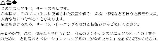
1-1. Fixtures and Adjustment Equipment |
|
||
1-1-1. Fixtures |
|
|
|
|
|
|
|
Illust No. Part No. |
Description |
Usage |
|
|
|
|
|
1 |
A-8322-296-A |
Extension Boards Assembly |
Plug-in boards check/adjustment |
|
|
(EX-655/656/657/658/667, and Stays) |
|
|
|
|
|
1-A |
A-8321-274-A |
EX-655 Board |
|
1-B |
A-8321-275-A |
EX-656 Board |
|
1-C |
A-8321-277-A |
EX-657 Board |
|
1-D |
A-8321-278-A |
EX-658 Board |
|
1-E |
A-8321-276-A |
EX-667 Board |
|
1-F |
3-193-678-01 |
Stay |
|
2 |
J-6001-820-A |
Drum Eccentricity Gauge (3) |
Drum eccentricity adjustment |
3J-6001-830-A Drum Eccentricity Gauge (2)
4 |
J-6026-110-A |
Multi Burst Chart |
Camera adjustment |
|
J-6026-130-B |
Gray Scale Chart (transparent type) (4:3) |
|
|
|
|
|
|
Commercially |
Gray Scale Chart (reflective type) (4:3) |
|
|
available |
|
|
|
|
|
|
|
J-6394-080-A |
Gray Scale Chart (transparent type) (16:9) |
|
5J-6029-140-B Pattern Box PTB-500
6 |
J-6035-070-A |
IC External Tool (CT-2101) |
Extraction of IC (PLCC type) |
|
7 |
J-6080-840-A |
Inspection Mirror |
Video tracking adjustment |
|
8 |
J-6087-000-A |
Drum Eccentricity Gauge (5) |
Drum eccentricity adjustment |
|
9 |
J-6152-450-A |
Wire Clearance Check Gauge |
Clearance check |
|
1 |
|
|
|
|
|
|
C |
|
|
|
A |
D |
E |
F |
|
|
|
||
|
B |
|
|
|
2 |
|
|
3 |
|
6 |
7 |
|
10 |
|
JB- |
|
OOOO |
DVW-790WS/709WS/707 |
1-1 |
DVW-790WSP/709WSP/707P P2V1
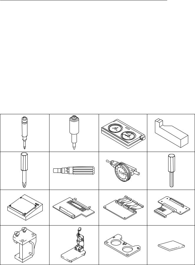
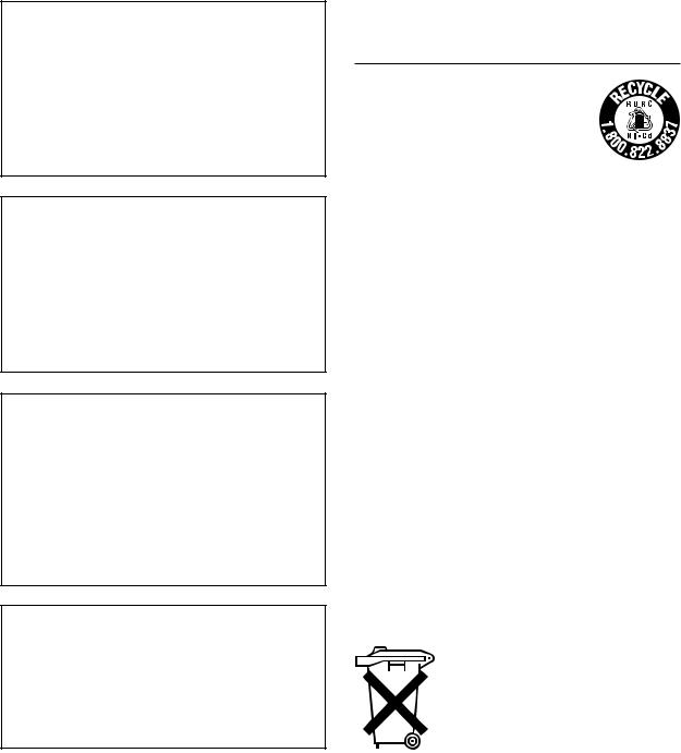
1-1. Fixtures and Adjustment Equipment
Illust No. |
Part No. |
Description |
Usage |
0 |
J-6322-420-B |
Tape Guide Adjustment Driver (45) |
Tape path adjustment |
|
J-6322-420-3 |
TG Driver Spare Bit (45) |
|
|
|
|
|
!- |
J-6323-530-A |
Stop Washer Fastening Tool |
Stop washer installation |
!= |
J-6323-890-A |
FWD Back Tension Measuring Cassette |
FWD back tension adjustment |
![ |
J-6324-150-A |
Reel Table Height Adjustment Tool |
Reel height adjustment |
!] |
J-6325-110-A |
Torque Driver Bit (for M1.4) |
Tightening screws |
|
J-6325-380-A |
Torque Driver Bit (for M2) |
|
|
|
|
|
!\ |
J-6325-400-A |
Torque Driver (for 3 kg) |
|
!; |
J-6325-530-A |
Drum Eccentricity Gauge (6) |
Drum eccentricity adjustment |
!' |
J-6326-120-A |
Hexagonal Bit (1.5 mm) |
Tightening screws |
!, |
J-6420-840-A |
Channel Condition Checker |
REC current adjustment |
!. |
J-6420-900-A |
MB Translate Board |
HN board operation check |
@/ |
J-6420-910-A |
TP Tool |
TP harness for tape path adjustment |
@- |
J-6420-930-A |
Extension Harness, 100 pin |
HN board operation check |
@= |
J-7031-630-A |
PG-163, 40-pin Positioning Tool |
Positioning 40-pin |
@[ |
J-7032-150-A |
PG-215, 40-pin CN Positioning Tool |
Positioning 40-pin connector |
@] |
J-7032-610-A |
Cassette Reference Plate |
Reel height adjustment |
@\ |
3-184-527-01 |
Cleaning Cloth |
Cleaning |
0 |
!- |
|
MW |
|
- |
|
389 |
!] |
!\ |
!, |
!. |
@= |
@[ |
1-2 |
DVW-790WS/709WS/707 |
|
DVW-790WSP/709WSP/707P P2V1 |
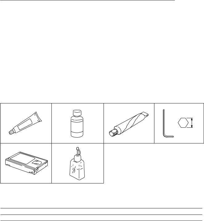
1-1. Fixtures and Adjustment Equipment
Illust No. |
Part No. |
Description |
Usage |
|
@; |
|
7-432-950-03 |
Sealant (TSE-392W) |
For water drop-proof |
@' |
|
7-661-018-18 |
Oil |
Lubricant |
@, |
|
7-662-010-08 |
Grease, SGL-701 (20 g) |
|
@. |
|
7-700-736-04 |
Hexagonal Wrench (d=2.5 mm) |
Screws removal |
|
|
7-700-736-05 |
Hexagonal Wrench (d=1.5 mm) |
|
|
|
|
|
|
|
|
7-700-736-06 |
Hexagonal Wrench (d=0.89 mm) |
|
|
|
|
|
|
#/ |
|
8-960-073-01 |
Alignment Tape, ZR5-1 |
Digital video/audio adjustment (NTSC) |
|
|
8-960-073-11 |
Alignment Tape, ZR2-1 |
Video tracking adjustment (NTSC) |
|
|
|
|
|
|
|
8-960-073-51 |
Alignment Tape, ZR5-1P |
Digital video/audio adjustment (PAL) |
|
|
|
|
|
|
|
8-960-073-61 |
Alignment Tape, ZR2-1P |
Video tracking adjustment (PAL) |
|
|
|
|
|
#- |
|
9-919-573-01 |
Cleaning Fluid |
TTP cleaning |
__ |
|
Commercially |
Digital Betacam Video Cassette, |
For recording |
|
|
available |
BCT-D6/D12/D22/D32/D40 |
|
|
|
|
|
|
|
|
|
Cleaning Tape, BCT-D12CL |
Cleaning video heads |
|
|
|
|
|
@; |
|
@' |
|
|
d |
#/ |
|
#- |
1-1-2. Adjustment Equipment |
|
|
Equipment |
Model Name |
Remarks |
Oscilloscope |
Tektronix 2465B |
|
Analog composite waveform/ |
Tektronix 1780R |
For DVW-790WS/709WS/707 |
|
vector monitor |
|
|
|
Tektronix 1781R |
For DVW-790WSP/709WSP/707P |
||
|
|||
|
|
|
|
Color monitor |
BVM-1410 |
|
|
|
|
|
|
White/black monitor |
__ |
|
|
|
|
|
DVW-790WS/709WS/707 |
1-3 |
DVW-790WSP/709WSP/707P P2V1
1-2. Using the Extension Boards
1-2. Using the Extension Boards
The extension boards for the plug-in boards check are available separately as spare parts.
See the table below to extend applicable board :
Board to be |
Extension board |
Reference |
|
checked |
|
|
|
|
|
|
|
DCP board assembly |
|
|
|
|
(side A) |
EX-655 and EX-656 |
Section 1-2-1 |
|
|
|
|
|
(side B) |
EX-657 |
Section 1-2-2 |
|
|
|
|
DVP board assembly |
|
|
|
|
(side A) |
EX-655 and EX-656 |
Section 1-2-1 |
|
|
|
|
|
(side B) |
EX-658 |
Section 1-2-2 |
|
|
|
|
SV-210 board |
EX-667 |
Section 1-2-3 |
|
|
|
|
|
DC-DC converter |
|
|
|
|
|
|
|
DIF-75 board |
|
|
|
(BKDW-702) |
|
|
|
|
|
|
|
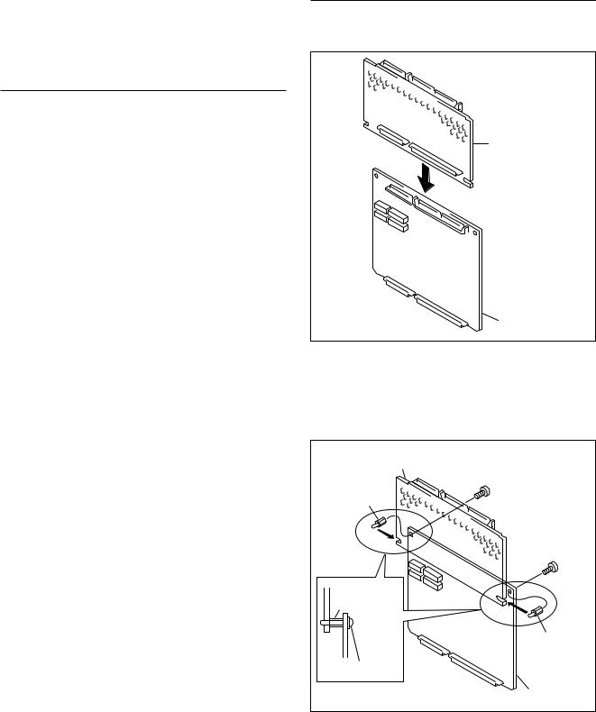
1-2-1. Using the EX-655 and EX-656 Boards
The EX-655 and EX-656 boards are always connected and used in a pair.
To check/adjust the side A of the DCP and DVP board assemblies, use these extension boards.
These boards are intended for the following use:
.EX-655 Board+EX-656 Board :
For the side A of the DCP/DVP board assembly check
Procedure
1. Connect the EX-656 board to the EX-655 board.
EX-656 board
EX-655 board
2.Slide in the two supplied supports (DP3) between the EX-655 board and the EX-656 board so that the protrusion of the support insert in the slot of the EX-656 board.
3.Secure the supports (DP3) using the two supplied screws from the EX-655 board side.
EX-656 board |
|
Support (DP3) |
M 2x4 |
(supplied |
|
accessory) |
(supplied accessory) |
|
M 2x4 |
|
(supplied |
|
accessory) |
Support (DP3) |
|
|
Support (DP3) |
|
(supplied |
M 2x4 |
accessory) |
|
|
|
EX-655 board |
1-4 |
DVW-790WS/709WS/707 |
DVW-790WSP/709WSP/707P P2V1

4.Remove the DCP or DVP board assembly to be checked.
5.Insert the EX-655 board into the slot for the DCP or DVP board assembly which is removed in step 4.
6.Connect the DCP or DVP board assembly to the EX656 board.
When extending the DCP board assembly
Follow the steps 7 and 8 described below:
7.Reconnect the harnesses removed from the DCP-17 board (CN12 and CN13) to the EX-655 board (CN12 and CN13).
8.Connect the EX-655 board (CN120 and CN130) to the DCP-17 board (CN12, CN13) with the two harnesses supplied.
CN12 |
|
|
CN13 |
|
|
Harnesses |
DCP board |
|
(supplied |
assembly |
|
accessories) |
|
|
CN130 |
EX-656 board |
|
EX-655 board |
||
CN120 |
||
CN12 |
|
|
CN13 |
|
DVW-790WS/709WS/707
1-2. Using the Extension Boards
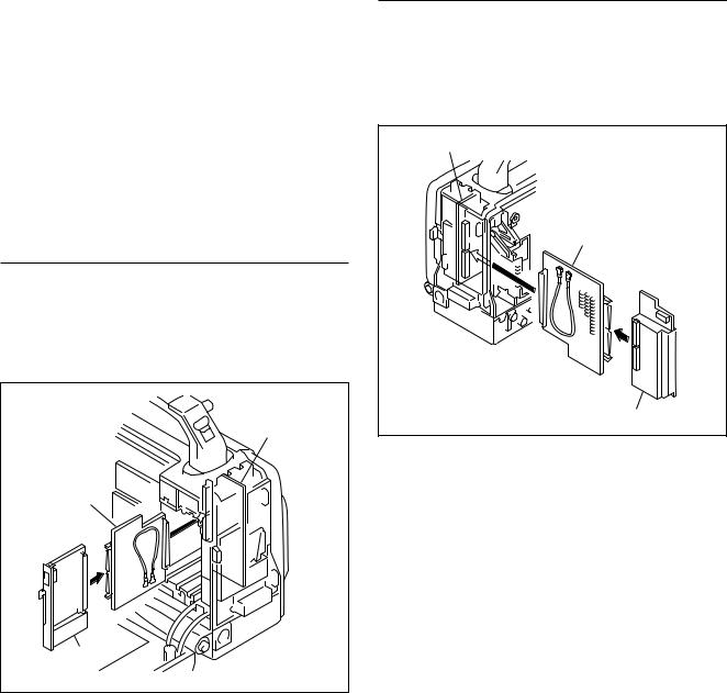
1-2-2. Using the EX-657 and EX-658 Boards
These boards are intended for the following use:
. EX-657 board : For the side B of DCP board assembly check
. EX-658 board : For the side B of DVP board assembly check
Procedure
1.Pull the DCP and DVP board assemblies out.
2.Insert the EX-657 board into the slot for the DCP board assembly.
3.Insert the EX-658 board into the slot for the DVP board assembly.
EX-658 board |
EX-657 |
board |
4.Connect the DCP board assembly to the EX-657 board.
5.Connect the DVP board assembly to the EX-658 board.
6.Hitch the two supplied stays on the hooks as shown in the figure to support the DCP and DVP board assemblies.
Hook |
|
|
DVP board |
Hook |
|
assembly |
||
|
||
DCP board assembly |
Stays |
|
|
(supplied accessories) |
|
|
1-5 |
DVW-790WSP/709WSP/707P P2V1
1-2. Using the Extension Boards
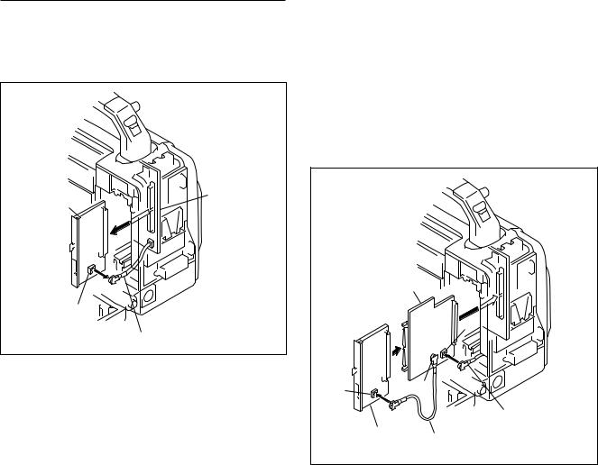
1-2-3. Using the EX-667 Board
The EX-667 board is intended for check of the following boards/part:
. SV-210 Board
. DC-DC Converter
. DIF-75 Board (BKDW-702)
n
The coaxial cable fixed on the EX-667 board is used for extending the DIF-75 board.
SV-210 Board
1.Pull the SV-210 Board out.
2.Insert the EX-667 board into the slot, and then push it to connect the MB-811 board.
3.Connect the SV-210 board to the EX-667 board.
MB-811 board
EX-667 board
SV-210 board
1-6
DC-DC Converter
1.Pull the DC-DC Converter out.
2.Insert the EX-667 board into the slot, and then push it to connect the MB-811 board.
3.Connect the DC-DC converter to the EX-667 board.
MB-811 board
EX-667 board
DC-DC converter
DVW-790WS/709WS/707
DVW-790WSP/709WSP/707P P2V1
DIF-75 Board (Optional Board: BKDW-702)
1.Disconnect the coaxial cable from the connector (CN2) on the DIF-75 board, and then pull the board out.
DIF-75 board |
MB-811 board |
(BKDW-702)
CN2
Coaxial cable
DVW-790WS/709WS/707
1-2. Using the Extension Boards
2.Disconnect the fixed coaxial cable from the connector (CN2) on the EX-667 board.
3.Insert the EX-667 board into the slot, and then push it to connect to the MB-811 board.
4.Reconnect the coaxial cable disconnected in step 1 to the connector (CN2) on the EX-667 board.
5.Engage the DIF-75 board to the EX-667 board.
6.Connect the coaxial cable disconnected from the EX-667 board in step 2 to the connector (CN2) on the DIF-75 board.
MB-811
 board
board
EX-667 board
CN2
CN2 |
CN22 |
|
|
Coaxial cable |
DIF-75 board |
Coaxial cable |
|
|
|
(supplied accessory) |
1-7
DVW-790WSP/709WSP/707P P2V1
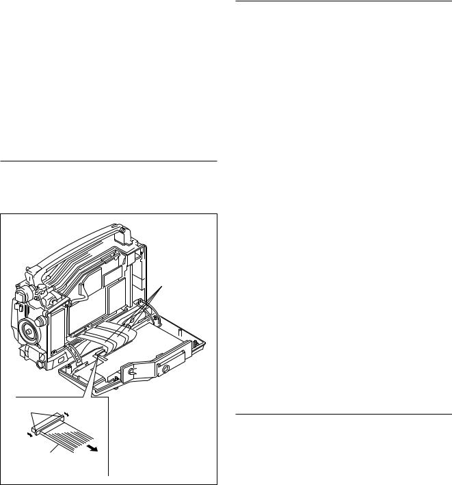
1-3. Disconnecting/Reconnecting Flexible Card Wires
1-4. IC Link
1-3. Disconnecting/Reconnecting
Flexible Card Wires
The three flexible card wires are used in the connection of the MB-810 board and the TC-101 board.
Be careful not to bend forcedly these flexible card wires. Crease of wire can seriously shorten its life.
n
Turn off the power, and then unplug the power cord or remove the battery before disconnecting/reconnecting the wires.
Disconnecting
1.Slide portions A in the direction of the arrow to unlock the connector, and then pull the flexible card wire out.
Flexible card wire |
Slide portions A |
flexible card wire |
Reconnecting
1.Check to see that the conductive surface (silver side) of the flexible card wire is not soiled with dust.
2.Slide portions A in the direction of the arrow, and then insert the flexible card wire into the connector with the
conductive surface (silver side) down. n
Be sure to insert the wire straightforward.
3.Slide portions A in the reverse direction to lock the connector.
1-4. IC Link
w
The IC link is critical for safe operation.
To avoid danger of a fire or electric shock, be sure use the specified component as a spare part when replacing it.
c
Replacement of the IC link of the plugged-in unit may be hazardous.
Be sure to turn off the power, and then unplug the cord from the DC IN connector before replacing the IC link.
An IC link is mounted on the B side of the HP-93 board. This will blow when the overcurrent flows because of internal circuit failure. If it blows, check the circuit for overcurrent after turning off the power.
And then, replace the IC link with specified part.
Board |
Ref. No. |
Description |
Part No. |
HP-93 |
F1 |
IC Link 2A |
1-533-282-21 |
|
|
|
|
1-8 |
DVW-790WS/709WS/707 |
DVW-790WSP/709WSP/707P P2V1
1-5. Notes on CCD Unit
1-6. Description on EEPROM/NV-RAM Data
1-5. Notes on CCD Unit
1-5-1. Spare CCD Units
The CCD units listed below are available separately.
Order the applicable unit by CCD unit model through a sales channel for the CCD unit replacement.
Camcorder |
CCD unit model |
CCD block type*1 |
DVW-790WS |
BKDW-C790W (UCJ) |
ILA |
|
|
|
DVW-790WSP |
BKDW-C790WP (EK) |
IMA |
|
|
|
DVW-709WS |
BKDW-C709W (UCJ) |
IJA |
|
|
|
DVW-709WSP |
BKDW-C709WP (EK) |
IKA |
|
|
|
DVW-707 |
BKDW-C707 (UCJ) |
INA |
|
|
|
DVW-707P |
BKDW-C707P (EK) |
IOA |
*1 : As for the detail on the CCD block type, refer to Section 1-5-2.
1-5-2. Description on CCD Block Number
Every CCD unit has its own ID number called CCD block number. It shows the CCD block type and serial number for the CCD block.
The CCD block number label is put in the CCD unit.
Example : ILA xxxxx
 Serial number for the CCD unit
CCD block type
As for the procedure for replacing the CCD unit, refer to Section “3-2-1. Replacing the CCD Unit”.
1-6. Description on EEPROM/NV-RAM Data
The table below gives the stored data of EEPROMs/NV-RAM on the printed circuit boards:
Board |
Ref. No. |
EEPROM/NV-RAM |
Stored data |
Reference |
DCP-17 |
IC152 (C3) |
NV-RAM |
All value of setup menu |
Section 1-7 |
|
|
|
|
|
|
IC140 (D5) |
EEPROM |
Special gamma table data |
Section 1-7 |
|
|
|
|
|
ES-23 |
IC18 (B2) |
EEPROM |
Board adjustment data |
Section 1-8 |
|
|
|
|
|
IF-716 |
IC102 (D4) |
EEPROM |
Model name and serial number |
__ |
|
|
|
|
|
m
.The part numbers of these ICs which data is blank or factory-set are specified in “Section 1. Spare Parts” of the Maintenance Manual Part 2 Vol.2.
.As for the IC102 on the IF-716 board, it is impossible to write the original data into the new IC.
When replacing the IF-716 board, remove the IC102 on the new IF-716 board and replace with the used IC on the former board.
If it becomes necessary to replace with a new IC, contact your local Sony Service Center/Sales Office.
DVW-790WS/709WS/707 |
1-9 |
DVW-790WSP/709WSP/707P P2V1

1-7. Note on the DCP-17 Board Replacement 1-8. EEPROM on the ES-23 Board
1-7. Note on the DCP-17 Board Replacement
EEPROM/NV-RAM
c
Operation of the unit elevates the temperature of the IC package. Heated IC package may result in injury. Replace the IC after turning off the power and ample time for the IC to cool off.
The EEPROM (IC123) and NV-RAM (IC140) on the DCP-17 board store data which was written by the customer. When replacing them with a new ICs, the former data is reset to the factory setting.
If necessary, remove the IC123/IC140 on the former DCP-17 board, and then reattach it to the new board.
Ref. No. (Address) |
Data stored |
IC152 (C3/DCP-17) Whole settings of the setup menu (User-written, and service engineerwritten settings*1)
IC140 (D5/DCP-17) Special gamma table data*2
(User-written setting)
*1 : Refer to Section “3-1. Engineer Mode (Setup Menu)” in the Maintenance Manual Part 1 to re-set the engineer mode.
*2 : If your customer does not use the special gamma, it is not necessary to replace the IC140.
Setting/Adjustment After Board Replacement
Refer to the following sections to set/adjust the DCP-17 board after replacing.
. Maintenance Manual Part 1 “1-10-3. DCP-17 Board”
.“Section 7 *1 or 8*2. Camera System Electrical Adjustments”
*1 : For DVW-790WS/790WSP/709WS/709WSP only *2 : For DVW-707/707P only
1-10
1-8. EEPROM on the ES-23 Board
c
Operation of the unit elevates the temperature of the IC package. Heated IC package may result in injury. Replace the IC after turning off the power and ample time for the IC to cool off.
The EEPROM (IC18) on the ES-23 board store the following data.
Ref. No. (Address) |
Data stored |
IC18 (B2/ES-23) |
Adjustment data |
|
(encoder factory setting) |
|
|
n
The part number of IC which is not adjusted is specified in the Section 1. Spare Parts List in the Maintenance Manual Part 2 Vol.2.
If the IC18 is replaced with a new IC of this part number, follow the steps below to re-set the data.
In case of the ES-23 board replacement, it is not necessary to re-set data of the IC18 because its board is factoryadjusted.
Adjusting After EEPROM Replacement
1.Enter the service mode. (Refer to the following steps
(1) to (3).)
(1)Turn off the power.
(2)Turn on the switch S4-1 on the DCP-17 board.
(3)Turn on the POWER switch.
2.Perform the following camera system electrical
alignments.
. ENC OUT Adjustment
(Refer to Section 7-4*1 or 8-4*2.)
. TEST OUT Level Adjustment (Refer to Section 7-5*1 or 8-5*2.)
*1 : For DVW-790WS/790WSP/709WS/709WSP only *2 : For DVW-707/707P only
DVW-790WS/709WS/707
DVW-790WSP/709WSP/707P P2V1

1-9. Note on the IF-716 Board Replacement
c
Operation of the unit elevates the temperature of the IC package. Heated IC package may result in injury. Replace the IC after turning off the power and ample time for the IC to cool off.
The EEPROM (IC102) on the IF-716 board store the following data.
Ref. No. (Address) |
Data stored |
IC102 (D4/IF-716) |
Model and Serial No. |
|
|
n
As for the IC102 on the IF-716 board, it is impossible to write the original data into a new IC.
When replacing the IF-716 board, remove the IC102 on the new IF-716 board and replace with the used IC on the former board.
If it becomes necessary to replace with a new IC, contact your local Sony Service Center/Sales Office.
1-10. Note on the RE-160 and RE-161 Boards
The RE-160 and RE-161 boards and electrical parts mounted on its boards cannot be replaced.
If these parts are out of order, replace the whole DC-DC converter.
1-11. DC Fans Precaution
The bearing of the DC fan is a precision part. Be careful not to grasp the fan by its blade, bump, and drop it. Unduly shock may damage the bearing in the fan, that can result in abnormal noise during the fan operation.
DVW-790WS/709WS/707
1-9. Note on the IF-716 Board Replacement 1-10. Note on the RE-160 and RE-161 Boards 1-11. DC Fans Precaution 1-12. Setting/Adjusting After Board Replacements
1-12. Setting/Adjusting After Board
Replacements
The boards required setting/adjusting after replacement are as follows :
Board |
Setting/Adjusting after Replacement |
AD-155 |
7-8./8-8. R/B AD Gain Adjustment |
|
|
AXM-21 |
Switch/Slit land settings |
|
(Refer to the MM P1*1, Section 1-10-1.) |
CNB-11 |
Slit land settings |
|
(Refer to the MM P1*1, Section 1-10-2.) |
DCP-17 |
Switch settings |
|
(Refer to the MM P1*1, Section 1-10-3.) |
|
Section 7./8. Camera System Electrical |
|
Alignment |
|
(when very good accuracy is required) |
|
|
DVP-17 |
Switch settings |
|
(Refer to the MM P1*1, Section 1-10-4.) |
|
6-5-2. Playback Equalizer Adjustment, |
|
6-5-3. REC Current Automatic Adjust- |
|
ment |
|
|
ES-23 |
7-2./8-2. VCO CONT Frequency Check |
|
|
IF-716 |
Replace the IC102 with the used one on |
|
the former board. |
|
|
TC-101 |
Switch settings |
|
(Refer to the MM P1*1, Section 1-10-6.) |
|
6-2-1. Battery End Detection Voltage |
|
Adjustment |
|
|
TG-206*2 |
8-2. VCO CONT Frequecy Check |
TG-207*3 |
Switch settings |
|
(Refer to the MM P1*1, Section 1-10-7.) |
VA-191 |
7-8./8-8. R/B AD Gain Adjustment |
|
|
CCD unit |
5-1. Tape Path Alignment |
|
7-2./8-2. VCO CONT Frequecy Check |
7-3./8-3. AD Clock Phase Adjustment
MM P1*1 Section 4./5. Camera Sysytem
Electrical Alignment
*1 : Maintenance Manual Part 1 *2 : For DVW-707/707P only
*3 : For DVW-790WS/790WSP/709WS/709WSP only
1-11
DVW-790WSP/709WSP/707P P2V1

Section 2
Setup Menu
This section describes the service mode that is part of the Setup Menu which appears on the viewfinder screen. For the VTR menu, refer to the Maintenance Manual, Part 1, Section 3-2.
2-1. Service Mode
The circuit boards that are supplied as repair parts have already been adjusted before shipment from the factory. However, the adjustment values somewhat differ for each product. After replacing any of the circuit boards relating to the video signal of the camera, use the service mode to perform accurate adjustment.
Data Structure
Data structure of the setup menu is described as shown below.
Setup values of the setup menu = Fixed data (absolute value) +Service mode setup value (relative value) +Engineer mode setup value (relative value) +User mode setup value (relative value)
Setup values of the setup menu (adjustment value)
User mode data (relative value)
Engineer mode data (relative value)
Service mode data (relative value)
Fixed data (absolute value)
Stored in setup card
 Default data when shipped
  from factory
.When any item is adjusted using the service mode, the adjustment value of that item in the engineer mode and that in the user mode are returned to 0.
.The fixed data has been stored in IC15 on the DR-387 board, IC140 on the DCP-17 board and IC18 on the ES-23 board respectively. The set values in the user, engineer and service modes are stored in IC123 on the DCP-17 board.
.The set values in the user, engineer and service modes have been set to 0 when the unit is shipped from the factory.
.Refer to the Operation Manual and Maintenance Manual, Part 1, Section 3 for the user mode and the engineer mode.
.When the RM-B150/P9 remote control is connected to operate the system externally, there are some items whose set values cannot be changed or to which set values are not reflected. Refer to Section 2-1-3, “Setup Menu List” for details.
How to Return the Set Values of Each Mode to the Default Values
The set values of each mode can be returned to the default values using the setup menu.
Refer to the items on the DATA RESET page in Section “2-1-2 Contents of Setup Menu” for details.
About the Setup Card
.When a setting is saved in a setup card, the set value in the user mode and that in the engineer mode are stored separately.
.The fixed data differs for each product. When the same setup card is used for the camera adjustment using the service mode before and after replacing the board or for adjusting multiple cameras, the same fixed data and the same setup data in the service mode can be obtained.
Therefore, the desired value should be set using a typical camera as the reference camera in both the user mode and engineer mode, and the value should be saved in a setup card. When a board is replaced or other cameras are to be matched, adjust the camera in the service mode first, then download the data that has been saved in the setup card, to the camera.
How to Enter the Service Mode
When the MENU/ON/OFF switch has been set to the ON position during normal operation after the main power is turned on, the camera enters the user mode. To make the camera enter the service mode, set the following switch, turn on the main power and then set the MENU/ON/OFF switch to the ON position.
S4-1/DCP-17 board → ON
DVW-790WS/709WS/707 |
2-1 |
DVW-790WSP/709WSP/707P P2V1

2-1. Service Mode
2-1-1. Fundamental Operation of the Setup Menu
Switch description
MENU ON/OFF/PAGE switch
VTR |
GAIN |
OUTPUT WHITE BAL |
OFF |
CANCEL/PRST |
|
ON |
|
|
PAGE |
ITEM |
ASSIGNABLE |
|
MENU |
|
|
|
|
POWER |
|
|
ON |
OFF |
|
MENU CANCEL/PRST/ITEM switch
Rotary encoder
1.MENU ON/OFF/PAGE switch
The MENU ON/OFF/PAGE switch is used to display the setup menu or to switch the display items in units of page. When lid is closed, the MENU ON/OFF/PAGE switch is automatically set to the OFF position.
ON |
: Displays the setup menu. |
OFF |
: Exits from the setup menu. |
PAGE : Selects another page of the setup menu
2.MENU CANCEL/PRST/ITEM switch
The MENU CANCEL/PRST/ITEM switch is used to select the desired item or to cancel setting or to recover the default setting when the MENU ON/OFF/PAGE switch is ON.
CANCEL/PRST : Cancels the already executed setting, or returns to the default setting.
ITEM : Selects the desired item.
3.Rotary encoder
Rotate: Moves to another page or to another item, or to change the setup value. Press: Sets the page, or enters the setup value modification mode.
Operation (Using the MENU switch)
1.Set the MENU ON/OFF/PAGE switch to ON position.
2.To move to another page, set the MENU ON/OFF/PAGE switch to PAGE. (Moves to the next page every time when this switch is set.)
3.To move to another item, set the MENU CANCEL/PRST/ITEM switch to ITEM. (The cursor moves to the next item every time when this switch is set.)
Press the rotary encoder to enter the setup value modification mode.
4.Rotate the rotary encoder to modify the setup value.
5.To exit from the setup menu, turn OFF the MENU ON/OFF/PAGE switch.
Operation (Using the rotary encoder)
1.Set the MENU ON/OFF/PAGE switch to ON position.
2.To move to another page, rotate the rotary encoder. (A page is set by pressing the rotary encoder.)
3.To move to another item, rotate the rotary encoder. (An item is set by pressing the rotary encoder.) Press the rotary encoder to enter the setup value modification mode.
4.To modify the setup value, rotate the rotary encoder .
5.To exit from the setup menu, turn OFF the MENU ON/OFF/PAGE switch.
2-2 |
DVW-790WS/709WS/707 |
DVW-790WSP/709WSP/707P P2V1

2-1. Service Mode
2-1-2. Contents of Setup Menu
This section describes all menu items that appear when the service mode is selected. (The items shown in halftone 
 appear only in the service mode.)
(Values in square [|] of the Setup column indicate the default value when shipped from factory.)
No. |
Page |
Item |
Setup |
Description |
||
1 |
MARKER 1/3 |
SAFETY ZONE |
[ON]/OFF |
Sets the safety zone marker display to ON or OFF. |
||
|
|
|
|
|
|
|
|
|
|
|
|
|
|
|
|
SAFETY AREA |
80%/ |
90% |
/100% |
Sets the safety zone area to 80 %, 90 % or 100 %. |
|
|
|
|
|
|
|
|
|
CENTER |
ON/[OFF] |
Sets the center marker display to ON to OFF. |
||
|
|
|
|
|
|
|
|
|
CENTER H |
X ([0]) |
Moves the center marker horizontally. |
||
|
|
|
|
|
|
|
|
|
CENTER V |
X ([0]) |
Moves the center marker vertically. |
||
|
|
|
|
|
|
|
2 |
MARKER 2/3 |
BOX CURSOR |
ON/[OFF] |
Sets the box cursor display to ON or OFF. |
||
|
|
|
|
|
|
Note : The box cursor does not appear in the following cases. |
|
|
|
|
|
|
The WIDE SCREEN page BOX/4:3/14:9 LIMIT is set to |
|
|
|
|
|
|
any other item than BOX. |
|
|
|
|
|
|
The WIDE SCREEN page BOX/4:3/14:9 MODE is set to |
|
|
|
|
|
|
4:3, while the VF ASPECT is set to 16:9A or 16:9B. |
|
|
|
|
|
|
|
|
|
BOX WIDTH |
X ([0]) |
Changes the width of the box cursor. |
||
|
|
|
|
|
|
|
|
|
BOX HEIGHT |
X ([0]) |
Changes the height of the box cursor. |
||
|
|
|
|
|
|
|
|
|
BOX H |
X ([0]) |
Moves the box cursor horizontally. |
||
|
|
|
|
|
|
|
|
|
BOX V |
X ([0]) |
Moves the box cursor vertically. |
||
|
|
|
|
|
|
|
3 |
MARKER 3/3 |
TEST OUT MIX |
ON/[OFF] |
Turns ON/OFF the function of outputting the VF marker to TEST OUT. |
||
|
|
|
|
|
|
|
|
|
RET MIX |
ON/[OFF] |
Turns ON/OFF the function of mixing the VF marker with return video. |
||
|
|
|
|
|
|
|
|
|
TEST OUT VF DISP ON/[OFF] |
Turns ON/OFF the function of outputting the character to TEST OUT |
|||
|
|
|
|
|
|
where the character is displayed on VF when the VF DISPLAY |
|
|
|
|
|
|
switch is set to ON. |
|
|
|
|
|
|
|
|
|
TEST OUT MENU |
ON/[OFF] |
Turns ON/OFF the function of outputting the menu to TEST OUT |
||
|
|
|
|
|
|
where the menu is displayed on VF when the MENU ON/OFF/PAGE |
|
|
|
|
|
|
switch is set to ON. |
|
|
|
|
|
|
Note : When an RM is connected, the menu is forced to be outputted |
|
|
|
|
|
|
regardless of this menu setting. |
|
|
|
|
|
|
|
|
|
RM VF MENU INH. |
[ON]/OFF |
ON : The menu is not displayed even through the MENU switch |
||
|
|
|
|
|
|
is set to ON when an RM is connected. |
|
|
|
|
|
|
OFF : The menu is displayed when the MENU switch is set to ON |
|
|
|
|
|
|
even though an RM is connected. |
|
|
|
|
|
|
|
4 |
VF DISP 1/2 |
DISP MODE |
1/2/[3] |
|
Set the display mode. (For details, refer to the Operation Manual.) |
|
|
|
|
|
|
|
|
|
|
EXTENDER |
[ON]/OFF |
Sets the extender display to ON or OFF. |
||
|
|
|
|
|
|
|
|
|
ZOOM |
[ON]/OFF |
Sets the zoom position display to ON or OFF. |
||
|
|
|
|
|
|
|
5 |
VF DISP 2/2 |
FILTER |
[ON]/OFF |
Sets the filter display to ON or OFF. |
||
|
|
|
|
|
|
|
|
|
WHITE |
[ON]/OFF |
Sets the white balance display to ON or OFF. |
||
|
|
|
|
|
|
|
|
|
GAIN |
[ON]/OFF |
Sets the gain selection value display to ON or OFF. |
||
|
|
|
|
|
|
|
|
|
SHUTTER |
[ON]/OFF |
Sets the shutter speed/mode display to ON or OFF. |
||
|
|
|
|
|
|
|
|
|
TAPE |
[ON]/OFF |
Sets the tape remaining display to ON or OFF. |
||
|
|
|
|
|
|
|
|
|
AUDIO |
[ON]/OFF |
Sets the CH-1 audio level display to ON or OFF. |
||
|
|
|
|
|
|
|
|
|
IRIS |
[ON]/OFF |
Sets the iris value display to ON or OFF. |
||
|
|
|
|
|
|
|
DVW-790WS/709WS/707 |
2-3 |
DVW-790WSP/709WSP/707P P2V1

2-1. Service Mode
No. |
Page |
Item |
Setup |
Description |
6 |
MASTER GAIN |
LOW |
_3/[0]/3/6/9/12/18/ |
Sets the gain corresponding to the LOW, MIDDLE, HIGH and |
|
|
|
24/30/36/42/48 dB |
TURBO positions of the GAIN selector switch. |
|
|
|
|
|
|
|
MID |
_3/0/3/6/[9]/12/18/ |
Note : When the gain selection value is changed, the BLACK SET |
|
|
|
24/30/36/42/48 dB |
adjustment is required. |
|
|
|
|
|
|
|
HIGH |
_3/0/3/6/9/12/[18]/ |
|
|
|
|
24/30/36/42/48 dB |
|
|
|
|
|
|
|
|
TURBO |
_3/0/3/6/9/12/18/ |
|
|
|
|
24/30/36/[42]/48 dB |
|
|
|
|
|
|
7 |
SHOT ID |
ID-1 |
|
Shot ID setting (ID1 to ID4) |
|
|
ID-2 |
|
Sets the shot ID of a maximum of twelve characters using |
|
|
ID-3 |
|
alphanumeric character, symbol, and space. |
|
|
|
|
|
|
|
ID-4 |
|
|
|
|
|
|
|
8 |
SHOT DISP |
|
|
Selects the shot data to be super-imposed on color-bar signal. |
|
|
|
|
|
|
|
DATE |
ON/[OFF] |
Date |
|
|
|
|
|
|
|
TIME |
ON/[OFF] |
Time |
|
|
|
|
|
|
|
MODEL NAME |
ON/[OFF] |
Model name |
|
|
|
|
|
|
|
SERIAL NO. |
ON/[OFF] |
Serial No. |
|
|
|
|
|
|
|
CASSTTE NO. |
ON/[OFF] |
Cassette No. |
|
|
|
|
|
|
|
SHOT NO. |
ON/[OFF] |
Shot No. |
|
|
|
|
|
|
|
ID SELECT |
[OFF]/ID1/ID2/ |
The shot ID number that is selected by the SHOT ID page. |
|
|
|
ID3/ID4 |
|
|
|
|
|
|
9 |
SHUTTER |
|
|
The shutter mode/speed setting that can be selected by the |
|
|
|
|
SHUTTER switch, etc. |
|
|
|
|
|
|
|
EVS |
[ON]/OFF |
Turns ON/OFF the EVS mode. (DVW-709WS/709WSP/707/707P) |
|
|
|
|
Turns ON/OFF the super EVS (Enhanced vertical definition) mode. |
|
|
|
|
(DVW-790WS/790WSP) |
|
|
|
|
|
|
|
CLS |
[ON]/OFF |
Turns ON/OFF the CLS (clear scan) mode. |
|
|
|
|
(DVW-709WS/709WSP/707/707P) |
|
|
|
|
Turns ON/OFF the ECS (extended clear scan) mode. |
|
|
|
|
(DVW-790WS/790WSP) |
|
|
|
|
|
|
|
1/100 (NTSC) |
[ON]/OFF |
Shutter speed 1/100 (for NTSC) or 1/60 (for PAL) second in the |
|
|
1/60 (PAL) |
|
standard mode |
|
|
|
|
|
|
|
1/125 |
[ON]/OFF |
Shutter speed 1/125 second in the standard mode |
|
|
|
|
|
|
|
1/250 |
[ON]/OFF |
Shutter speed 1/250 second in the standard mode |
|
|
|
|
|
|
|
1/500 |
[ON]/OFF |
Shutter speed 1/500 second in the standard mode |
|
|
|
|
|
|
|
1/1000 |
[ON]/OFF |
Shutter speed 1/1000 second in the standard mode |
|
|
|
|
|
|
|
1/2000 |
[ON]/OFF |
Shutter speed 1/2000 second in the standard mode |
|
|
|
|
|
10 |
!’ LED |
|
|
OFF : The “!” lamp of VF does not turn on. |
|
|
|
|
ON : The “!” lamp of VF turns on when the following conditions |
|
|
|
|
are satisfied. |
|
|
MASTER GAIN |
[ON]/OFF |
The GAIN value is set to any value other than 0 dB. |
|
|
SHUTTER ON |
[ON]/OFF |
The SHUTTER switch is set to ON. |
|
|
WHITE PRESET |
ON/[OFF] |
The WHITE BAL switch is set to PRST. |
|
|
ATW RUN |
ON/[OFF] |
The ATW (automatic tracing white balance) is operating. |
|
|
EXTENDER ON |
[ON]/OFF |
Lens extender is being used. |
|
|
FILTER 2,3,4 |
ON/[OFF] |
Filter is set to any position other than 1. |
|
|
FILTER A,C,D |
ON/[OFF] |
Filter is set to any position other than B. |
|
|
|
|
(DVW-790WS/790WSP/709WS/709WSP only) |
|
|
A.IRIS OVERRIDE |
ON/[OFF] |
Reference value of the automatic iris control is et to any value |
|
|
|
|
other than the standard value. |
|
|
|
|
|
2-4 |
|
|
|
DVW-790WS/709WS/707 |
DVW-790WSP/709WSP/707P P2V1

2-1. Service Mode
No. |
Page |
Item |
Setup |
Description |
11 |
SETUP CARD |
READ (→CAM) |
To be executed by |
Reads data from the setup card. |
|
|
|
pressing the rotary |
|
|
|
|
encoder. |
|
|
|
|
|
|
|
|
WRITE (→CARD) |
To be executed by |
Writes data to the setup card |
|
|
|
pressing the rotary |
|
|
|
|
encoder. |
|
|
|
|
|
|
|
|
ID EDIT |
|
The card ID can be set within ten characters using alphanumeric |
|
|
|
|
characters and symbols. |
|
|
|
|
|
|
|
WRITE PROTECT |
ON/[OFF] |
Turns ON/OFF the write-inhibit function into the setup card. |
|
|
|
|
|
|
|
WHITE DATA |
ON/[OFF] |
Turns ON/OFF the function of reading white balance correction |
|
|
|
|
value from the setup card. |
|
|
|
|
|
12 |
FUNCTION 1/2 |
TEST OUT |
[ENC]/R/G/B |
Selection of video signal to be output froth TEST OUT connector. |
|
|
|
|
Note : R-G or B-G can be selected when R-G/B-G SEL on the |
|
|
|
|
first page of OPERATION is set to ON. |
|
|
|
|
|
|
|
DETAIL |
[ON]/OFF |
Turns ON/OFF the function of adding detail signal to video for |
|
|
|
|
improving resolution power. |
|
|
|
|
|
|
|
APERTURE |
[ON]/OFF |
Sets the aperture correction to ON or OFF. |
|
|
|
|
|
|
|
SKIN TONE DTL |
ON/[OFF] |
Turns ON/OFF the skin tone detail function. |
|
|
|
|
|
|
|
MATRIX |
ON/OFF |
Turns ON/OFF the linear matrix correction function. |
|
|
|
*Default value |
The highly color saturation can be obtained when this item is set |
|
|
|
OFF (J) |
to ON. |
|
|
|
ON (Except J) |
|
|
|
|
|
|
|
|
GAMMA |
[ON]/OFF |
Turns ON/OFF the gamma correction function. |
|
|
|
|
|
|
|
BLACK GAMMA |
ON/[OFF] |
Turns ON/OFF the black gamma correction function. |
|
|
|
|
|
|
|
CHROMA |
[ON]/OFF |
Turns ON/OFF the function to add chroma signal. |
|
|
|
|
|
|
|
TEST SAW |
ON/[OFF] |
Turns ON/OFF the function to add the TEST signal to the video |
|
|
|
|
signal system forcibly. (Used during the video signal adjustment.) |
|
|
|
|
|
|
|
CROSS COLOR FLT |
ON/[OFF] |
Turns ON/OFF the function to reduce the cross-color of video |
|
|
|
|
signal. (NTSC only) |
|
|
|
|
|
13 |
FUNCTION 2/2 |
GENLOCK |
[ON]/OFF |
Turns ON/OFF the function of synchronizing the internal reference |
|
|
|
|
signal with the video signal that is input to GENLOCK IN connector. |
|
|
|
|
|
|
|
CAM RET. |
ON/[OFF] |
Turns ON/OFF the function of displaying the return video signal |
|
|
|
|
that is input to the GENLOCK IN connector, when the RET button |
|
|
|
|
on the lens is set to ON. |
|
|
|
|
|
|
|
FILTER INH. |
ON/[OFF] |
Turns ON/OFF the function of interlocking the filter with the white |
|
|
|
|
balance correction value. |
|
|
|
|
ON : The white balance correction value does not interlock with |
|
|
|
|
the color temperature conversion filter, but is memorized in |
|
|
|
|
the memory A and memory B respectively. |
|
|
|
|
OFF : The white balance correction value is memorized in the |
|
|
|
|
respective memories of memory A (4 memories) and |
|
|
|
|
memory B (4 memories) totaling 8 memories respectively. |
|
|
|
|
|
|
|
FIELD/FRAME |
[FIELD]/FRAME |
Sets the CCD read-out method. |
|
|
|
|
FIELD : Reading out in units of field. (Normal setting) |
|
|
|
|
FRAME : Reading out in units of frame. |
|
|
|
|
(Used when the higher vertical resolution is desired) |
|
|
|
|
Note : The FRAME reading has a more residual image than the |
|
|
|
|
FIELD reading. |
|
|
|
|
|
|
|
A.IRIS OVERRIDE |
ON/[OFF] |
Turns ON/OFF the iris override function. |
|
|
|
|
When the iris override function is set to ON, reference value of the |
|
|
|
|
AUTO iris adjustment can be modified by the rotary encoder when |
|
|
|
|
the MENU ON/OFF/PAGE switch is set to OFF. |
|
(continued) |
|
|
(5 steps: _1/2, _1/4, 0, +1/4, +1/2 steps of iris stop) |
|
|
|
|
|
DVW-790WS/709WS/707 |
|
|
2-5 |
|
DVW-790WSP/709WSP/707P P2V1

2-1. Service Mode
No. |
Page |
Item |
Setup |
Description |
||
13 |
FUNCTION 2/2 |
DCC FUNCTION |
FIX/[DCC]/ADP.K |
Selects the DCC function modes when the DCC switch is set to ON. |
||
|
|
SEL |
|
DCC |
|
: Normal mode |
|
|
|
|
|
||
|
|
|
|
|
|
(Dynamic range is set by the DCC ADJUSTMENT page.) |
|
|
|
|
FIX |
|
: Knee is corrected by the fixed dynamic range of 600%. |
|
|
|
|
ADP.K : Adaptive mode |
||
|
|
|
|
|
|
Detects an object which is occupying the largest area |
|
|
|
|
|
|
of a picture and automatically adjusts the knee point |
|
|
|
|
|
|
and knee slope to obtain the optimum level for the object. |
|
|
|
|
|
||
|
|
REAR BNC OUT |
[VBS]/SDI/OFF |
Selects the signal to be output from the rear panel VIDEO OUT |
||
|
|
|
|
connector when the SDI output board BKDW-702 is installed. |
||
|
|
|
|
VBS : Outputs the composite video signal. |
||
|
|
|
|
SDI |
: Outputs the SDI signal. |
|
|
|
|
|
OFF : Set to OFF when power saving is desired. |
||
|
|
|
|
|
||
|
|
VTR MODE |
ON/[OFF] |
Set to ON when an external VTR is controlled by the VTR START |
||
|
|
|
|
button as it is interlocked with the DVW, when an external VTR is |
||
|
|
|
|
connected via the CA-702. |
||
|
|
|
|
|
||
|
|
REC INHIBIT |
[ON]/OFF |
Set to OFF when you use a built-in VTR for recording even though |
||
|
|
|
|
CCU is connected via CA-705/755. |
||
|
|
|
|
Note : When this setup is set to OFF, a viewfinder can not be |
||
|
|
|
|
|
|
powered on. |
|
|
|
|
|
||
|
|
ASSIGNABLE SW |
[OFF]/RET/REC/ |
Selects function of the ASSINABLE button. |
||
|
|
|
TURBO/ |
OFF |
|
: No function assigned |
|
|
|
AUDIO/ATW/ |
|
||
|
|
|
RET |
|
: RET button |
|
|
|
|
LOOPR/F.SHT |
|
||
|
|
|
REC |
|
: VTR START button |
|
|
|
|
|
|
||
|
|
|
|
TURBO : TURBO GAIN button |
||
|
|
|
|
AUDIO |
: The ON/OFF switch of the function to display the |
|
|
|
|
|
|
|
AUDIO source on VF for each channel. |
|
|
|
|
ATW |
|
: The ON/OFF switch of the ATW function |
|
|
|
|
LOOPR : The ON/OFF switch of the loop recording function. |
||
|
|
|
|
|
|
(This item is displayed only when the picture cache |
|
|
|
|
|
|
board BKDW-703 is installed.) |
|
|
|
|
F. SHT |
: The ON/OFF switch of the frame shutter function. |
|
|
|
|
|
|
|
(This item is displayed only when the frame shutter unit |
|
|
|
|
|
|
BKDW-705 is installed.) |
|
|
|
|
|
||
14 |
WIDE SCREEN |
|
|
Note : This page is displayed only in DVW-790WS/790WSP/ |
||
|
|
|
|
|
|
709WS/709WSP only |
|
|
|
|
|
||
|
|
16:9/4:3 MODE |
[16:9]/4:3 |
Sets the aspect ratio of the video signal output from the VIDEO |
||
|
|
|
|
OUT and TEST OUT connectors. |
||
|
|
|
|
|
||
|
|
VF ASPECT |
[AUTO]/4:3/ |
Sets the aspect ratio on the viewfinder. |
||
|
|
|
16:9A/16:9B |
AUTO : Sets the aspect ratio set by 16:9/4:3 MODE setting. |
||
|
|
|
|
4:3 : Sets the aspect ratio to 4:3 regardless of 16:9/4:3 MODE |
||
|
|
|
|
|
|
setting. |
|
|
|
|
16:9A |
: Sets the aspect ratio to 16:9 regardless of 16:9/4:3 MODE |
|
|
|
|
|
|
|
setting (displays the area of 4:3 mode with the marker). |
|
|
|
|
16:9B |
: Sets the aspect ratio to 16:9 regardless of 16:9/4:3 MODE |
|
|
|
|
|
|
|
setting (video level is cut in half out of the safety zone |
|
|
|
|
|
|
area on the VF screen). |
|
|
|
|
|
||
|
|
BOX/4:3/14:9 |
[BOX]/4:3/14:9 |
Sets the function of the box cursor. |
||
|
|
LIMITS |
|
BOX : Operates as the normal cursor function. |
||
|
|
|
|
|||
|
|
|
|
4:3 |
: Displays the 4:3 area when the 16:9/4:3 MODE set to 16:9. |
|
|
|
|
|
14:9 |
: Displays the 14:9 area when 16:9 is selected by the above |
|
|
|
|
|
|
|
described 16:9/4:3 MODE. |
|
|
|
|
|
||
|
|
16:9 BARS ID |
ON/[OFF] |
Turns ON/OFF the function of adding the 16:9 display to the built- |
||
|
|
|
|
in color bar when 16:9 is selected by the above described 16:9/4:3 MODE. |
||
|
|
|
|
|
||
|
|
16:9 VF ID |
ON/[OFF] |
Turns ON/OFF the function of adding the 16:9 display to the VF screen |
||
|
|
|
|
when 16:9 is selected by the above described 16:9/4:3 MODE. |
||
|
|
|
|
|
|
|
2-6 |
|
|
|
|
|
DVW-790WS/709WS/707 |
DVW-790WSP/709WSP/707P P2V1
Loading...