


DXC-327BK
Sony DXC-327BK, DXC-327BF, DXC-327BH, DXC-327BL, DXC-327BPL Operating Instructions Manual
...
3-856-085-22(1)
Color V ideo Camera
Operating Instructions
Before operating the unit, please read this manual
thoroughly and retain it for future reference.
DXC-327BK/BL/BH/BF
DXC-327BPK/BPL/BPH/BPF
1996 by Sony Corporation
WARNING
To prevent fire or shock hazard, do not
expose the unit to rain or moisture.
To avoid electrical shock, do not open
the cabinet. Refer servicing to qualified
personnel only.
For the customers in the U.S.A.
This equipment has been tested and found to comply with
the limits for a Class A digital device, pursuant to Part 15 of
the FCC Rules. These limits are designed to provide
reasonable protection against harmful interference when the
equipment is operated in a commercial environment. This
equipment generates, uses, and can radiate radio frequency
energy and, if not installed and used in accordance with the
instruction manual, may cause harmful interference to radio
communications. Operation of this equipment in a residential
area is likely to cause harmful interference in which case the
user will be required to correct the interference at his own
expense.
CAUTION
RISK OF ELECTRIC SHOCK
DO NOT OPEN
CAUTION : TO REDUCE THE RISK OF ELECTRIC SHOCK,
DO NOT REMOVE COVER (OR BACK).
NO USER-SERVICEABLE PARTS INSIDE.
REFER SERVICING TO QUALIFIED SERVICE PERSONNEL.
This symbol is intended to alert the user to the
presence of uninsulated “dangerous voltage’’
within the product’s enclosure that may be of
sufficient magnitude to constitute a risk of
electric shock to persons.
This symbol is intended to alert the user to the
presence of important operating and
maintenance (servicing) instructions in the
literature accompanying the appliance.
You are cautioned that any changes or modifications not
expressly approved in this manual could void your authority
to operate this equipment.
The shielded interface cable recommended in this manual
must be used with this equipment in order to comply with the
limits for a digital device pursuant to Subpart B of Part 15 of
FCC Rules.
Owner’s Record
The model and serial numbers are located on the right
side. Record these numbers in the spaces provided
below. Refer to them whenever you call your Sony dealer
regarding this product.
Model No. Serial No.
2

Table of Contents
Introduction ..............................................................4
Composition of the DXC-327B-series Color
Video Camera ........................................... 4
Choosing from NTSC or PAL System................ 5
Notes on Using Accessories with the DXC-327B
Series Camera ........................................... 5
Precautions................................................................ 6
On Using and Storing the Camera.......................6
Managing Hyper-Sensitivity in the CCD Image
Sensor........................................................ 6
Features .....................................................................7
Location and Function of Parts...............................8
DXC-327B/327BP Camera Head........................8
CA-537/537P Camera Adaptor (optional) ........16
VCL-714BX Zoom Lens...................................18
DXF-601/601CE Electronic Viewfinder...........20
Accessory Attachment........................................... 22
Attaching/Detaching a Camera Adaptor ........... 22
Attaching a Videocassette Recorder.................. 24
Attaching the Zoom Lens and Optional Filter...25
Attaching and Adjusting the Electronic
Viewfinder .............................................. 27
Attaching a Microphone....................................29
Attaching/Detaching a Tripod ........................... 31
Connections .............................................................32
Connecting an S-VHS Format Portable VTR ... 32
Connecting a Portable VTR ..............................33
Connecting an External Microphone.................33
Connecting a Table-Top VTR........................... 34
Connecting a Camera Control Unit ................... 34
Connecting a Remote Control Unit ................... 36
Using the Camera with a VTR .......................... 37
Power Sources ......................................................... 39
Using a DC Power Supply ................................ 39
Using a Battery Pack .........................................40
Using Power Supplied Through the Camera
Adaptor....................................................42
Adjustment and Settings ........................................46
Reading Indications in the Electronic
Viewfinder ..............................................46
Reading the Viewfinder Screen Display Menu. 49
Adjusting the Viewfinder Screen Display.........50
Adjusting the Video Monitor ............................51
Adjusting the Iris............................................... 52
Selecting the Filter ............................................54
Adjusting the Black Balance .............................54
Adjusting the White Balance.............................56
Adjusting the Contrast.......................................58
Selecting the Shutter Speed...............................59
Advanced Operations ............................................. 60
Zoom Operation ................................................60
Adjusting Flange Focal Length .........................61
Doing Close-Ups ...............................................62
Adjusting the Sharpness of the Picture..............63
Selecting the Output Level ................................64
Checking the Video Level................................. 64
Synchronizing Two or More Cameras (Without
Using a Camera Control Unit) ................65
Title Characters Setting ..................................... 67
Connecting a Number of Cameras (Using a
Camera Control Unit)..............................70
Using the Optional Carrying Case ........................71
Specifications...........................................................72
Camera Head DXC-327B/327BP......................72
Camera Adaptor ................................................73
CA-537/537P (Optional) ...................................73
Zoom Lens VCL-714BX...................................73
Viewfinder DXF-601/601CE ............................ 73
Carrying Case LC-421 ......................................73
Accessories Supplied.........................................73
Optional Accessories and Recommended
Equipment........................................................74
Sample Video System Configuration ....................75
Glossary ...................................................................76
Basic Operations ..................................................... 43
Operating the Camera........................................43
Recording with a Portable VTR ........................ 44
Recording with a Table-Top VTR.....................44
Monitoring the VTR Picture and Audio Output 45
Index ........................................................................77
3
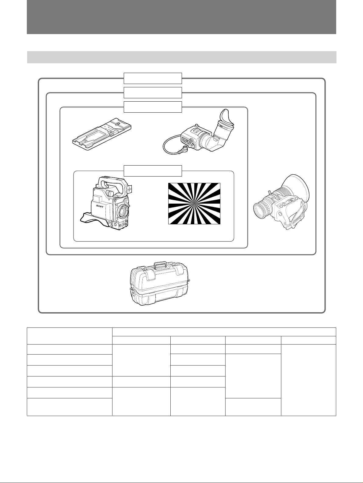
Introduction
Composition of the DXC-327B-series Color Video Camera
DXC-327BF/327BPF
DXC-327BK/327BPK
DXC-327BL/327BPL
VCT-U14 tripod attachment
DXC-327BH/327BPH
DXF-601/601CE viewfinder
VCL-714BX zoom lens
M
A
T
W
RET
Chart for flange focal
DXC-327B/327BP camera head
LC-421 carrying case
length adjustment
Composition Model
DXC-327BK/327BPK DXC-327BL/327BPL DXC-327BH/327BPH DXC-327BF/327BPF
DXC-327B/327BP camera head Yes Yes
VCL-714BX zoom lens Yes No
DXF-601/601CE viewfinder Yes No Yes
LC-421 carrying case No No
VCT-U14 tripod attachment
Chart for flange focal length Yes Yes Yes
adjustment
4

Choosing from NTSC or PAL
System
Notes on Using Accessories with
the DXC-327B Series Camera
The following explains the differences between the
NTSC and PAL system regarding accessory selection
for the DXC-327B series camera.
Some PAL components can operate on NTSC
equipment and vice-versa. In general, however, this is
not the case. You must use the type of equipment and
accessories that matches the signal system of your
camera. Use the DXC-327B-series camera within the
NTSC color system, and use the DXC-327BP series
camera within the PAL system.
• If you use the CA-537/537P Camera Adaptor (not
supplied) with this camera, operate the camera
according to the instructions in this manual.
• If you use the CA-327/327P Camera Adaptor (not
supplied), operate the camera according to the
instructions that come with the adaptor.
• If you use a zoom lens other than the VCL-714BX
zoom lens, operate the camera according to the
instructions that come with the lens. (For further
information on accessories, see “Optional
Accessories and Recommended Equipment”, on page
74.)
5
Precautions
On Using and Storing the Camera
This section explains how to safely use, store and
clean the camera.
When setting up the camera
•Do not attach the zoom lens without reading
“Attaching the Zoom Lens and Optional Filter” on
page 25. Attaching the lens incorrectly may damage
the lens.
•Do not directly connect the camera to an AC power
line. Use the recommended camera adaptor or use a
12 volt DC power source.
•Do not block air circulation about the camera to
prevent internal heat build-up.
When operating the camera
•Avoid rough handling or mechanical shock.
•Avoid strong magnetic fields to prevent signal
distortion.
•Avoid operating the camera in environments that
exceed the temperature range of –5˚C to +45˚C (23˚F
to 113˚F).
•Do not grip the camera by the viewfinder.
When using a supplied viewfinder
Do not leave the viewfinder so that sunlight can enter
the eyepiece lens. It is possible for sunlight focused
by the eyepiece to cause very high temperatures, and
melt the inside of the viewfinder
When storing and shipping the camera
•Cover the lens with the supplied lens cap when you
do not plan to use the video camera for an extended
period of time.
•When you transport the camera, repack it as it was
originally shipped. Do not discard the packing
carton. This affords maximum protection whenever
you ship the camera. Do not ship or transport the
camera in the carrying case alone.
•Store the camera with the viewfinder moved fully in
the direction opposite the viewfinder barrel and the
lock ring tightened. (See page 28.)
Managing Hyper-Sensitivity in the
CCD Image Sensor
Because of the high sensitivity of the CCD image
sensors, the following phenomena may appear on the
monitor screen while you are using the DXC-327Bseries color camera. These phenomena do not mean
that there is anything wrong with the camera.
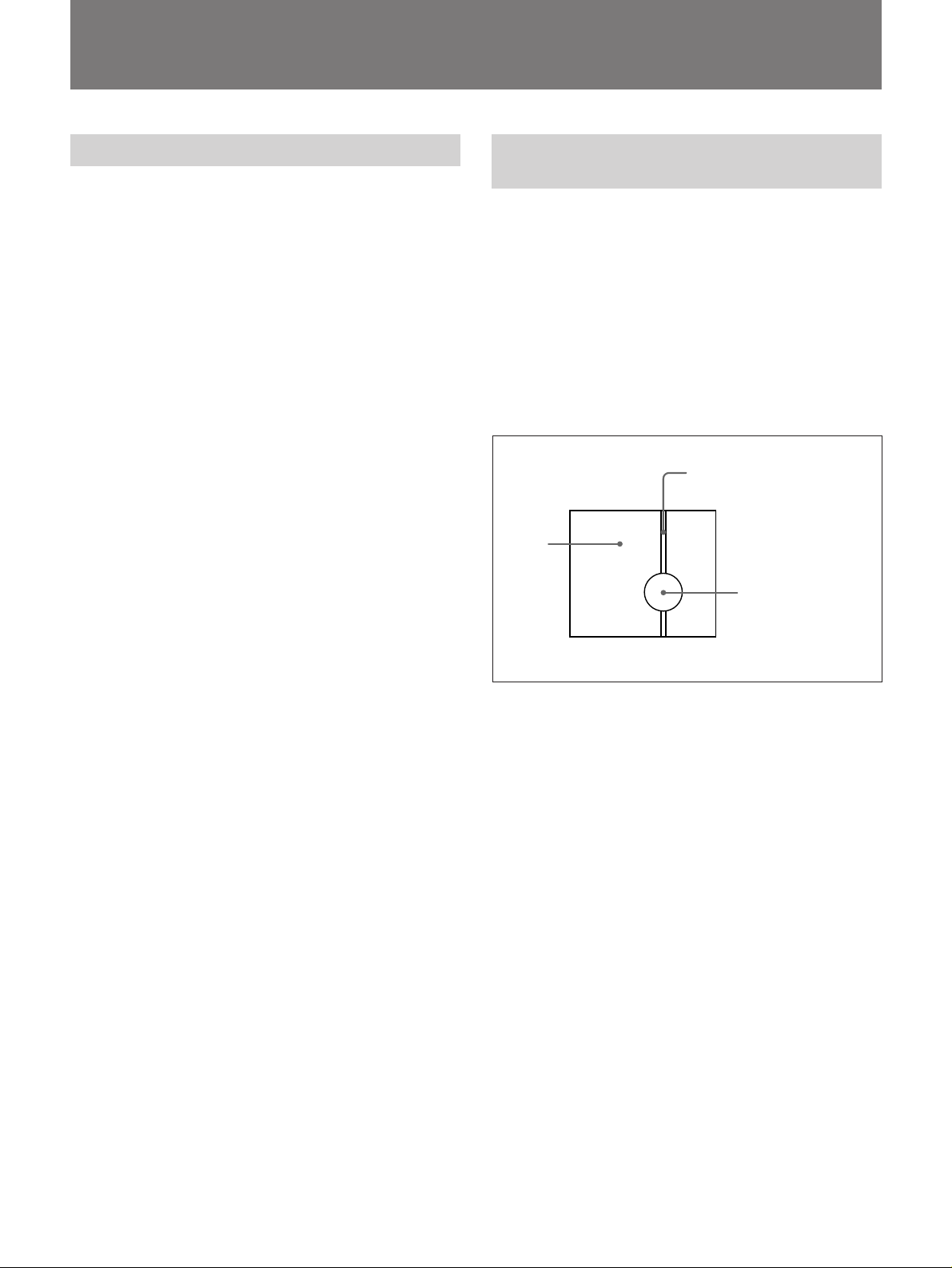
Vertical smear
Smear tends to happen when an extremely bright object
such as an electric light, fluorescent lamp, sunlight, or
strong reflection is being shot.
Light belt-like line
(smear phenomenon)
Video
monitor
screen
A very bright object is
shot. (Such as electric
light, fluorescent lamp,
sunlight, strong
reflected light)
White dots
White dots may appear in the video output if the
camera is used at very high temperatures.
Aliasing
Aliasing may occur when you shoot fine stripes or
straight lines. The lines appear jagged.
Poor pictures
You may not get a clear picture if the GAIN selector is
set to 18 dB when you are using the electronic shutter.
Use the electronics shutter under lighting conditions
where you can obtain a clear picture with the GAIN
selector set to the 0 or 9 dB position.
When cleaning the camera
•Clean the cabinet, panel and controls with a soft, dry
cloth or a cloth moistened with a mild detergent
solution.
•Do not use any type of solvent, such as alcohol or
benzine which might damage the finish.
If you have any questions about this camera, contact
your authorized Sony dealer.
6

Features
Power HAD™ Sensor CCD Chip design
The Power HAD™ Sensor CCD Chip design employs
1
three
/2-inch CCD (Charge Coupled Device) images
each having a total of about 380,000 (NTSC) or
440,000 (PAL) effective picture elements. The CCD
offers better picture quality over tube type pick-up
devices by providing;
•higher resolution and sensitivity
•lower lag, higher image burning resistance, and no
deflection distortion
•less vibration and magnetic field distortion
•higher S/N ratio that allows you to raise the video
output level by 9 dB or 18 dB to get a clear picture
under low light conditions.
Maximum system versatility
By attaching optional equipment you can expand the
usability of the camera:
•the CA-537/537P Camera Adaptor enables you to
control the camera via a camera control unit or VTR.
•the CA-325A/325AP or CA-325B enables multiple
outputs of RGB format signal.
•a Hi8 format videocassette recorder or a Betacam
format videocassette recorder PVV-3/3P, Pro 2000
series, turns your unit into a camcorder.
•the CCU-M5/M5P Camera Control Unit allow you to
use the camera as a studio camera.
•the various kinds of power sources (battery, AC and
DC) allow you to use the camera under many power
situations.
Viewfinder displays
So you don’t have to take your eye off what you are
shooting, the viewfinder displays adjustment
indications and warning. The viewfinder shows the
following four displays;
Characters: Show switch settings, warning
indications, and the title characters to be
superimposed.
Zebra pattern: Appears on the portion of the screen
where the video output level is about 70 to 80% IRE
(for NTSC) or 490 to 560 mV (for PAL). This pattern
acts as a reference when you manually adjust the iris.
Safety zone marker and center marker: Indicate the
safety zone for shooting and the center of the picture.
Status indicators: The REC/TALLY indicator flashes
to warn the connected VTR malfunctions, the BATT
indicator the weak power of the installed battery pack,
and the SHUTTER and GAIN UP indicators show the
setting status of the corresponding switches.
Electronic shutter
The built-in electronic shutter ensures better pictures
of fast moving objects with little blurring.
Automatic adjustment and memory
functions
The camera automatically adjusts white/black balance
as well as camera settings, and stores the adjustments
for later use.
7
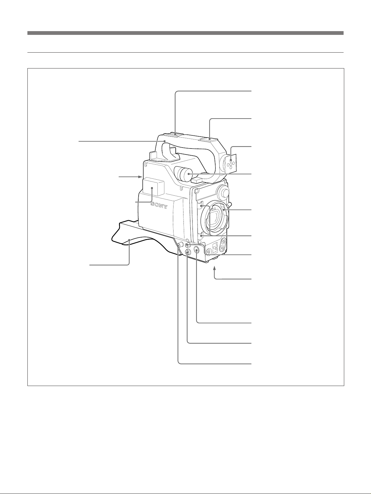
Location and Function of Parts
DXC-327B/327BP Camera Head
The DXC-327B/327BP Camera Head is the modular
core of this multipurpose camera system. Depending
on your purpose, connect VTRs and camera control
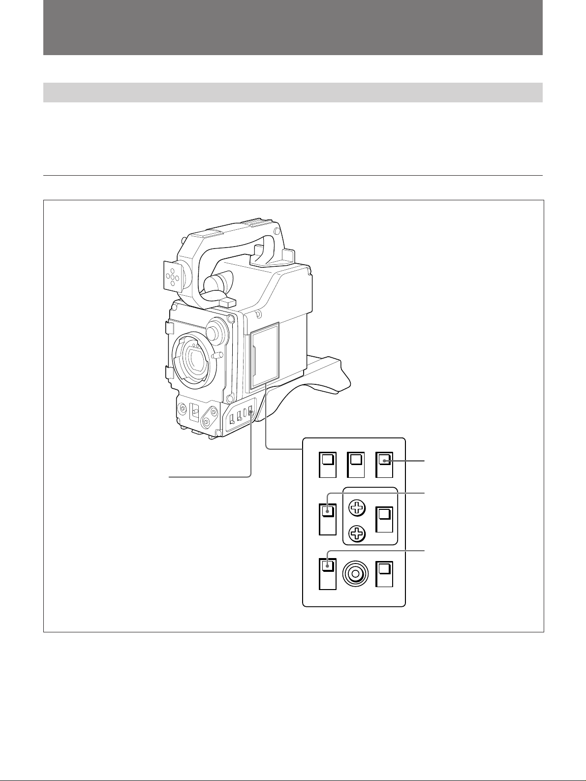
Camera head power supply and indications
POWER
WHITE
BAL
GAIN
units to it via the CA-537/537P or CA-327/327P
Camera Adaptor.
Inside the lid
1 POWER switch
2 ZEBRA switch
3 VF MARKER selector
4 DISP CHG switch
8

1 POWER switch
OFF: Turns the camera off.
ON SAVE: Select to save power. When you press the
VTR start button, there is a delay before recording
starts, but the amount of power consumed in this
mode is less than when the VTR is in stand-by
mode (STBY).
This function is activated only when the VTR has
the power saving function.
ON STBY: Select for a quick start. When you press
the VTR start button, recording starts immediately.
In this mode, power continues to be consumed
while the drum heads rotate.
2 ZEBRA switch
ON: Select to display the zebra pattern on the
viewfinder screen for manual iris adjustment. The
zebra pattern appears in the picture where the
video level is about 70 to 80% IRE (for NTSC) or
about 490 to 560 mV (for PAL). (See page 64.)
OFF: Select not to display the zebra pattern.
3 VF MARKER (viewfinder safety zone marker
and/or center marker) selector
Use this selector to display the safety zone marker and/
or center marker on the viewfinder screen.
OFF: Indicates neither of the markers.
1: Indicates the safety zone marker.
2: Indicates both of the markers.
4 DISP CHG (display change) switch
Push this switch to change the character display mode
of the viewfinder screen. (See page 49.)
9
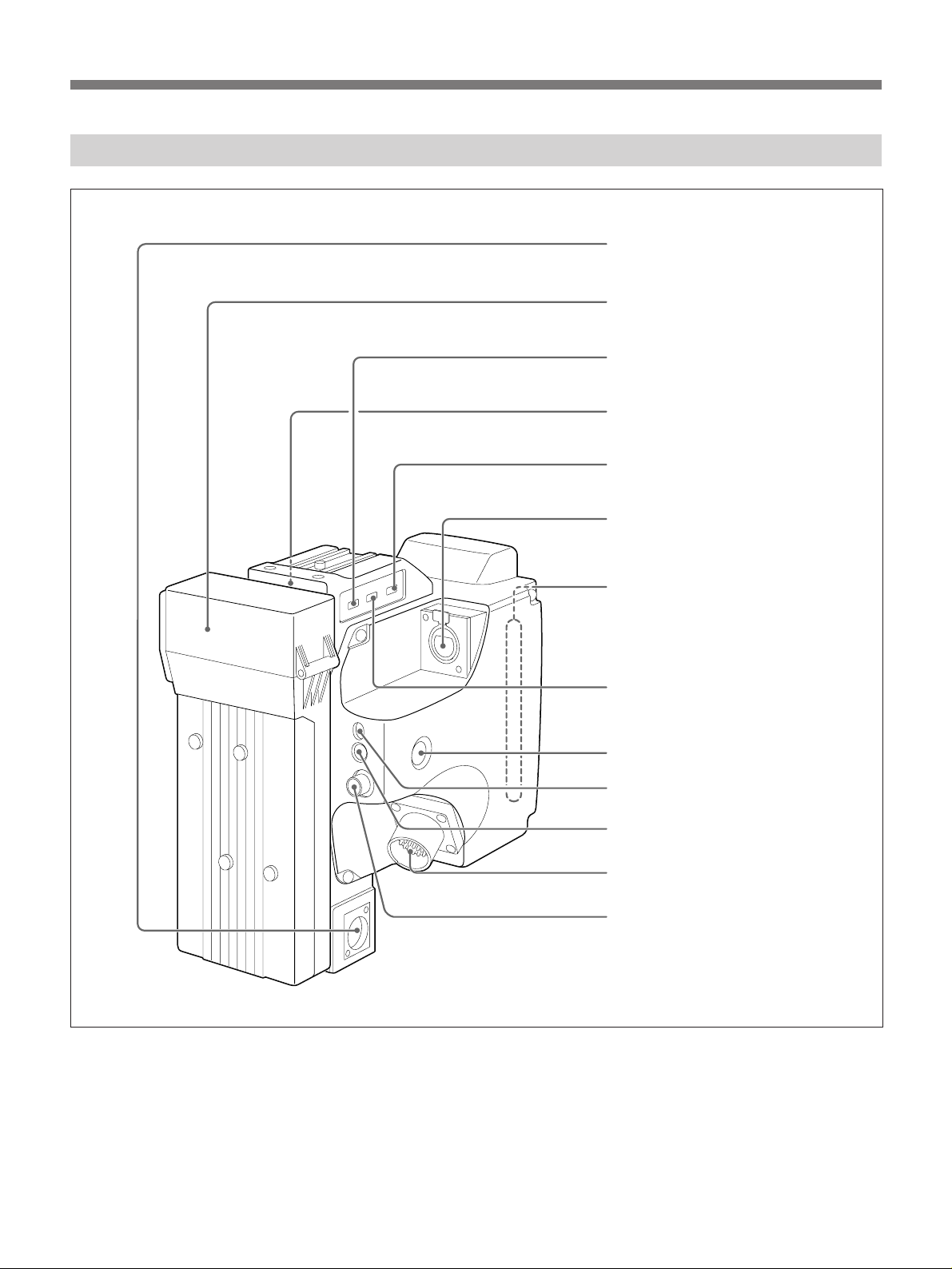
Location and Function of Parts
Camera head attachments and input/output connectors
Handle
7 Accessory shoe
8 Light receptacle
9 Viewfinder attachment
5 PRO 50-pin connector
6 Microphone holder attachment
Shoulder pad
0 Built-in microphone
!¡ Lens mount
!™ Cord clamps
LENS
VIDEO
OUT
VF
MONITOR
!£ LENS connector
Screw hole for tripod (U 1/4"-20UNC)
!¢ VF connector
!∞ REMOTE connector
10
!§ VIDEO OUT connector

5 PRO 50-pin connector
Connect to the 50-pin connector of the camera adaptor
or EVV-9000/9000P, PVV-1/1P/1A/1AP/3/3P. (See
pages 22 to 24.)
6 Microphone holder attachment
Attach an optional CAC-12 microphone holder here.
(See page 29.)
7 Accessory shoe
Attach an optional accessory such as an DXF-40B/
40BCE, DXF-50B/50BCE viewfinder here.
!¡ Lens mount
Attach the VCL-714BX Zoom Lens or another
1
/2"
lens and related equipment here.
!™ Cord clamps
Secure the viewfinder cord.
!£ LENS connector (6-pin)
Connect the lens cord when a
2
/3-inch lens is attached
to the camera head using an LO-32BMT Lens Mount
Adaptor or when an MVA-40 Microscope Adaptor is
attached to the camera.
8 Light receptacle
Attach an optional video light or other accessories
here.
9 Viewfinder attachment
Attach the DXF-601/601CE viewfinder here.
0 Built-in microphone
The built-in microphone allows you to make a sound
recording along with the video recording.
When an external microphone is connected to the MIC
IN connector on the CA-537/537P Camera Adaptor,
the built-in microphone does not function. We
recommend you use a uni-directional external
microphone to get a better sound recording when a
VTR such as a PVV-1/1P/1A/1AP/3/3P, EVV-9000/
9000P, is directly attached to this unit.
!¢ VF connector (8-pin)
Connect the viewfinder cord here.
!∞ REMOTE connector (10-pin)
To operate this camera from an RM-M7G Camera
Remote Control Unit, connect the camera to the
remote control unit via this connector. Make sure the
CAMERA SELECT switch on the bottom of the RMM7G is set to “1”, the factory preset position.
!§ VIDEO OUT (output) connector (BNC type)
To check the picture of the camera you are shooting,
connect to the input connector of a video monitor.
Also you can connect to the video input of a VTR.
Title characters display on the viewfinder screen
output from this connector.
11
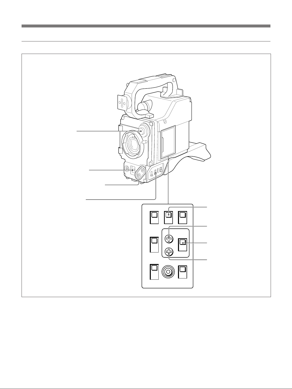
Location and Function of Parts
Camera head switches and controls
!¶ FILTER selector
!• AUTO W/B BAL switch
!ª UP/ON and DOWN/OFF buttons
@º WHITE BAL selector
POWER
WHITE
BAL
GAIN
Inside the lid
@¡ ABL switch
@™ SC PHASE control
@£ SC PHASE selector
@¢ H PHASE control
12

!¶ FILTER selector
Selects the appropriate filter according to lighting
conditions.
Filter number Color temperature Lighting conditions
1 3200K Iodine lamp, sunrise
or sunset
2 5600K+1/16ND
3 5600K Cloudy or rainy
1)
ND: Neutral density filter
1)
Bright outdoor
!• AUTO W/B BAL (automatic white/black
balance adjustment ) switch
Select “A” or “B” with the WHITE BAL selector and
push this switch to WHT to automatically adjust white
balance. To automatically adjust black balance, push
this switch to BLK. You can do this irrespective of the
WHITE BAL selector setting. The setting value is
stored in the camera's memory. When you release this
switch, the switch returns to the center position
automatically.
!ª UP/ON and DOWN/OFF buttons
Press either of these buttons with the DISP CHG
switch to make one of the following six settings to:
•Set the title characters (see page 67.)
•Turn on/off the LOW LIGHT indication (see page
47.)
•Adjust the reference level of the automatic iris (see
page 53.)
•Adjust the detail level (see page 63.)
•Adjust the master pedestal level (see page 58.)
•Adjust the shutter speed (see page 59.)
@º WHITE BAL (white balance memory) selector
A or B: Select A or B to make the camera use the
white balance setting stored in memory position A
or B.
PRE: Set to PRE when there is no time to adjust the
white balance. This function provides a factorypreset white balance value for a color temperature
of 3200K for the selected FILTER selector
position.
@¡ ABL (automatic black level) switch
When the entire picture is too bright, such as during
outdoor shooting, set this switch to ON. A wellcontrasted picture will be obtained.
@™ SC (subcarrier) PHASE control
Turn this control to fine tune the SC phase using a
small screwdriver. Do this after roughly adjusting the
SC phase using the SC PHASE selector (see page 66.)
Do this adjustment when you are using two or more
cameras simultaneously.
@£ SC (subcarrier) PHASE selector
Switch this selector to 0˚ or 180˚ to roughly adjust the
SC phase difference between the gen-lock input and
the video output signals when using two or more
cameras simultaneously. (See page 66.)
@¢ H (horizontal) PHASE control
Turn this control to adjust the H phase difference
between the gen-lock input and video output signals
using a small screwdriver. (See page 66.)
13
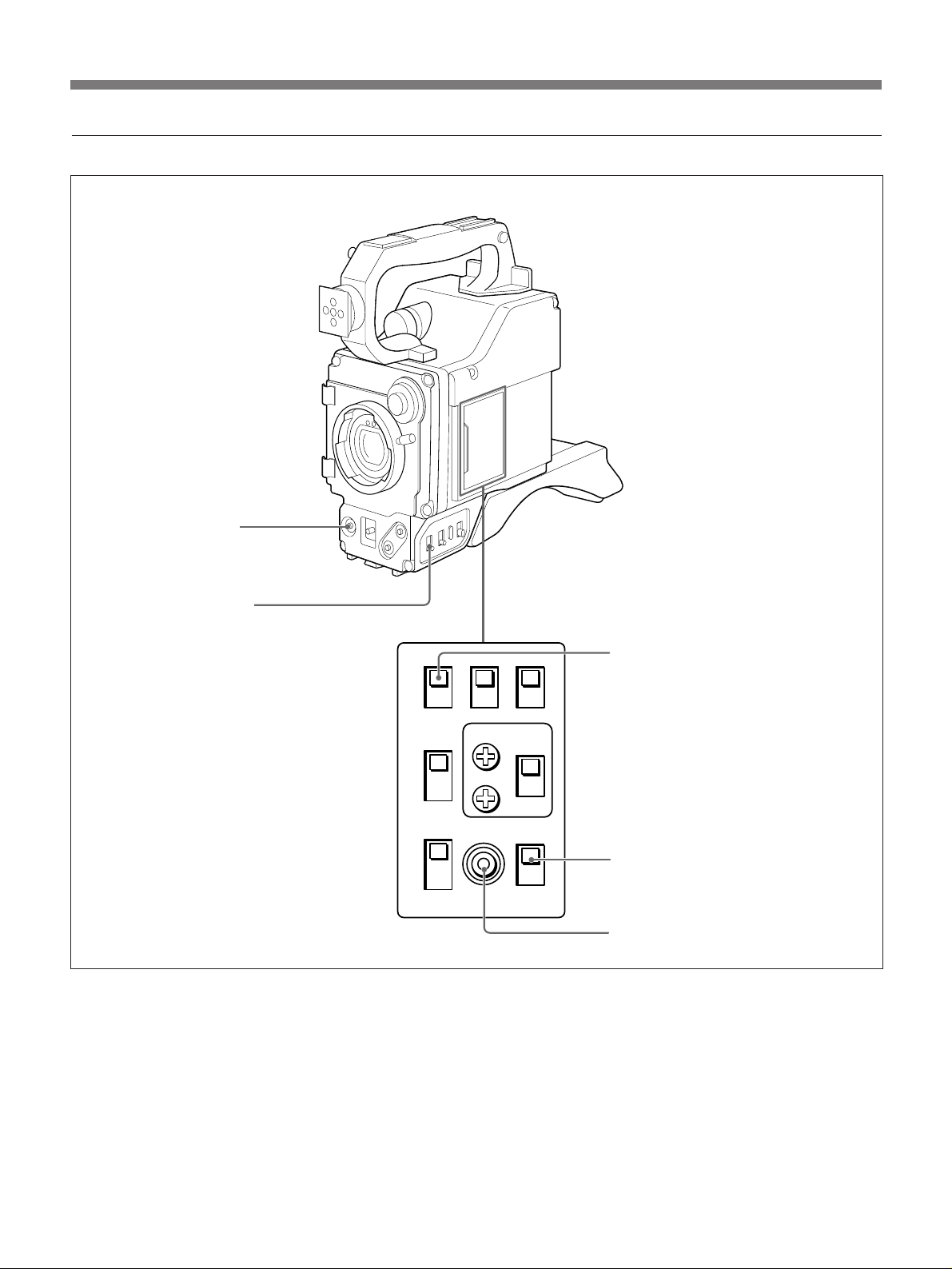
Location and Function of Parts
Camera head output selectors
@∞ VTR button
POWER
WHITE
BAL
GAIN
@§ GAIN selector
Inside the lid
@¶ SHUTTER switch
@• BARS switch
@ª REC REVIEW button
14

@∞ VTR button
When connecting the camera to a portable VTR, press
this button to start and stop recording.
When connecting the camera to a CCU-M7/M7P or
CCU-M5/M5P, keep this button depressed to monitor
the return video pictures on the viewfinder. Release it
to monitor the camera pictures.
@§ GAIN selector
Select a higher setting to lighten dark pictures.
@¶ SHUTTER switch
Flip this switch to control the electronic shutter.
ON: Flip to this position to activate the electronic
shutter. To select the shutter speed, use the UP/
ON or DOWN/OFF button. (See page 59.)
OFF: Flip to this position to deactivate the electronic
shutter.
@• BARS (color bar generation) switch
ON: Set to this position to display the color bars on
the viewfinder or video monitor screen when
adjusting its contrast and brightness. The color
bars are output to the viewfinder, video monitor or
other connected equipment from the following
connectors.
• VIDEO OUT connector
• VF connector
• REMOTE connector
• VTR/CCU/CMA connector (on the camera
adaptor)
OFF: Set to this position for normal operation.
@ª REC (record) REVIEW button
Press this button when using a VTR such as an EVV9000/9000P, PVV-1/1P/1A/1AP/3/3P, with this
camera to check the recorded picture while recording.
(For details, refer to the operations manual for the
cassette recorder.)
15
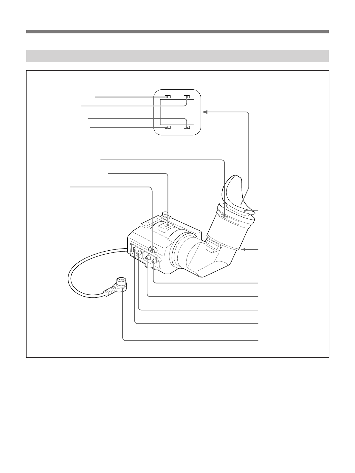
Location and Function of Parts
CA-537/537P Camera Adaptor (optional)
1 DC IN connector
2 Battery case
3 MIC POWER switch
4 EARPHONE jack
5 VTR SELECT switch
6 MIC IN connector
7 PRO 50-pin connector
!£ MIC LEVEL switch
!¡ VTR START/RETURN VIDEO button
!™ INTERCOM volume control
0 INTERCOM connector
8 VTR/CCU/CMA connector
9 GEN LOCK IN connector
16

Power supply
1 DC IN (input) connector (XLR-4 pin)
Connect an external DC power source (12 volt DC)
here to supply power to the camera adaptor and
camera.
When the power is supplied from this connector,
power supplied from a battery pack or from the VTR/
CCU/CMA connector is not used.
8 VTR/CCU/CMA connector (26-pin)
Connect a VTR, CCU-M7/M7P or CCU-M5/M5P
Camera Control Unit or CMA-8A/8ACE Camera
Adaptor here.
9 GEN LOCK IN (gen-lock input) connector
(BNC-type)
Connect the gen-lock sync signal (VBS or BS) for
synchronization here.
2 Battery case
Insert an NP-1B battery pack (not supplied) here.
3 MIC (microphone) POWER switch
ON: When you use the microphone of a phantom
powering system, set the switch to this position.
The power is supplied to the microphone from the
MIC IN connector.
OFF: When you use a microphone other than a
phantom powering system, set the switch to the
OFF position.
Input and output connectors
4 EARPHONE jack (minijack)
Connect an earphone here to monitor the playback or
recording sound from the VTR.
Note
Some type of VTR may not let you monitor the sound
output from the VTR. (See page 45).
5 VTR SELECT switch
Use this switch according to the type of VTR
connected to the camera. (See page 37).
Caution
Be sure to set the VTR SELECT switch to the correct
VTR type; otherwise, the VTR will not operate
properly.
0 INTERCOM connector
Connect a DR-100A intercom headset here. The DR100A enables communication between the camera and
the connected CCU-M7/M7P or CCU-M5/M5P
Camera Control Unit or video switcher.
Switches and controls
!¡ VTR START/RETURN VIDEO button
When a portable VTR is connected to the VTR/
CCU/CMA connector: Press this button to start and
stop recording.
When the CCU-M7/M7P or CCU-M5/M5P Camera
Control Unit is connected: Keep this button
depressed to monitor the return video picture, and
release it to monitor the camera picture.
!™ INTERCOM volume control
Controls the volume level through the DR-100A
Intercom Headset.
!£ MIC (microphone) LEVEL switch
Set this switch according to the sensitivity of the MIC
IN on the VTR and CCU. If the sensitivity is high, set
it to a minimum of –20 dB; if it is low, set it to a
maximum of –60 dB. (Refer to the operations manual
of the VTR.)
6 MIC IN (microphone input ) connector
(XLR 3-pin)
Connect an external microphone here.
7 PRO 50-pin connector
Connect to the 50-pin connector on the camera head.
17
Location and Function of Parts
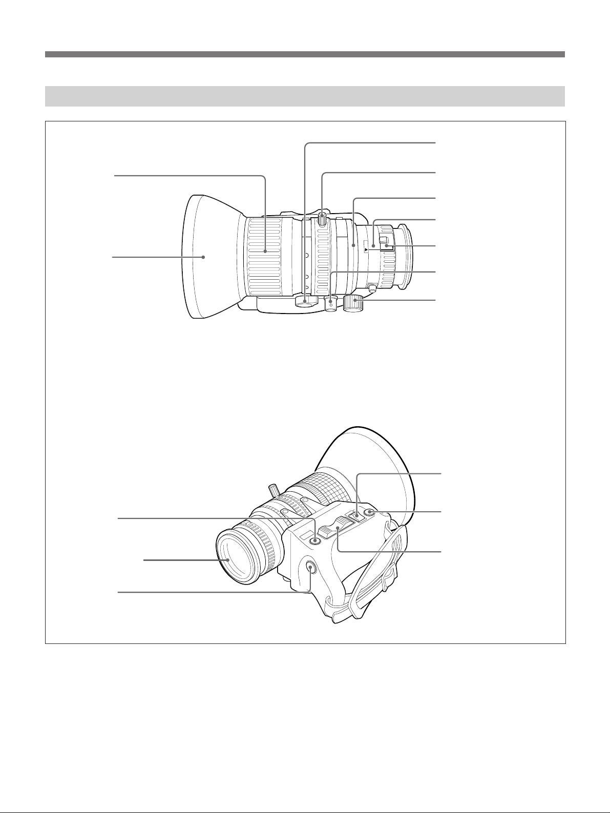
VCL-714BX Zoom Lens
8 ZOOM selector
1 Focus ring
Lens hood
9 Manual zoom lever
5 Iris ring
15
ft
m5321.5
oo
10
30
5 7 10 15
1.4
2
7.5
2.8
5.6 4
8
11
16
C
MACRO
F.f
2 Ff adjustment ring
3 MACRO ring and button
4Focus remote control
connector
0Zoom remote control
connector
!™ RET button
Lens connector (7-pin)
!£ VTR button
RET
6 IRIS selector
M
A
T
W
7Instant automatic iris
adjustment button
!¡ Motorized zoom switch
18

Focusing
1 Focus ring
To focus, turn this ring.
0 Zoom remote control connector (8-pin)
To do remote control zoom when the camera is
attached to a tripod, connect an LO-23 Lens Remote
Control Unit (optional) here.
2 Ff (flange focal length) adjustment ring
To adjust the Ff, release the screw and turn the ring.
3 MACRO (close-up) ring and button
To do close-up, turn the MACRO ring while sliding
the button.
4 Focus remote control connector (3-pin)
Not used.
Iris adjustment
5 Iris ring
To manually adjust the iris, turn this ring with the iris
selector set to M.
6 IRIS selector
A (automatic): Select to adjust the iris automatically.
M (manual): Select to adjust the iris manually.
7 Instant automatic iris adjustment button
To automatically adjust the iris during manual iris
adjustment, keep this button depressed. When the
button is released, the iris will remain at the value that
has just been obtained and will stay that way until you
manually adjust the iris again.
Zoom controls
8 ZOOM selector
S (servo): Select for motorized zoom action.
M (manual): Select for manual zoom.
!¡ Motorized zoom switch
For motorized zoom action, set the zoom selector to S.
Then, press either end of the motorized zoom switch,
W for a wide angle shot, and T for a telephoto shot.
Press the switch down all the way for faster zoom
action and only slightly for slow zoom action.
Recording controls
!™RET (return video) button
When a portable VTR is connected, keep this button
depressed to monitor the E-E picture on the
viewfinder screen. Release the button to monitor
the camera picture.
When a CCU-M7/M7P or CCU-M5/M5P Camera
Control Unit is connected, keep this button depressed
to monitor the return video picture on the
viewfinder screen. Release the button to monitor
the camera picture.
!£ VTR button
When a portable VTR is connected, press this button
to stop and start recording. This button has the
same function as the VTR button on the camera
head.
When a CCU-M7/M7P or CCU-M5/M5P Camera
Control Unit is connected, keep this button depressed
to monitor the return video picture on the
viewfinder screen. Release the button to monitor
the camera picture. Starting and stopping
recording is controlled on the VTR.
9 Manual zoom lever
To do manual zoom, move this lever with the ZOOM
selector set to M.
19
Location and Function of Parts
DXF-601/601CE Electronic Viewfinder
1 REC/TALLY indicator
2 BATT indicator
3 GAIN UP indicator
4 SHUTTER indicator
5 Eyepiece focusing knob
6 Accessory fixing screw hole
7 Tally lamp
REC/TALLY BATT
SHUTTER GAIN UP
Eye cup
8 Eyepiece release catch
9 BRIGHT control
0 CONTRAST control
!¡ PEAKING control
!™ TALLY switch
!£ Viewfinder connector
20

1 REC/TALLY (recording/tally) indicator (red)
•From the time when you press the VTR button on the
lens or camera head, this flashes until recording
starts, then stays on continuously during recording.
•When using a camera control unit, this lights when
this camera is selected.
•This is also used to indicate a fault.
8 Eyepiece release catch
To view the viewfinder screen directly, press this
catch, and hinge up the eyepiece.
9 BRIGHT (brightness) control
This adjusts the brightness of the viewfinder image.
(See page 50.)
2 BATT (battery) indicator (red)
This indicates when the battery capacity is low. (See
page 41.)
Note
When using a camera control unit, this indicator
flashes when you operate the controls, but this is not a
malfunction.
3 GAIN UP indicator (orange)
This lights when the gain is 3 dB or more.
4 SHUTTER indicator (red)
This lights when the SHUTTER switch is in the ON
position.
5 Eyepiece focusing knob
Turn this to adjust the viewfinder focus to match your
eyesight. (See page50.)
6 Accessory fixing screw hole
Attach optional video lights or other accessories here.
0 CONTRAST control
This adjusts the contrast of the viewfinder image. (See
page 50.)
!¡ PEAKING control
This adjusts the outline intensity of the viewfinder
image. (See page 50.)
!™ TALLY switch
Set this switch to ON position to use the tally lamp.
!£ Viewfinder connector
Connect this to the VF connector on the camera head.
Note on using a supplied viewfinder
Do not leave the viewfinder so that sunlight can enter
the eyepiece lens. It is possible for sunlight focused by
the eyepiece to cause very high temperatures, and melt
the inside of the viewfinder
7 Tally lamp
When the TALLY switch is in the ON position, this
operates in the same way as the REC/TALLY
indicator.
21
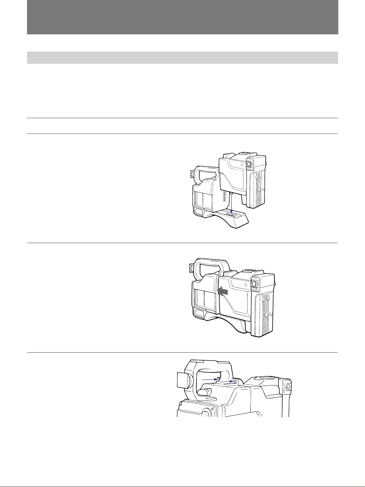
Accessory Attachment
Attaching/Detaching a Camera Adaptor
To use the DXC-327B/327BP camera head as a standalone camera, set up the camera head with a camera
control unit or portable VTR using as interface the
optional Sony CA-537/537P or CA-327/327P Camera
Attaching the CA-537/537P camera adaptor
1 Place the camera adaptor on
the camera head aligning the
guide with the guide hole.
2 Push the camera adaptor
forward along the grooves
until its 50-pin connector locks
into the PRO 50-pin connector
on the camera.
Adaptor. Refer to the CA-327/327P operations
manual for instructions on how to attach and detach
that unit. Refer to the below procedure to attach the
CA-537/537P Camera Adaptor.
Camera head
3 Fix the camera adaptor to the
camera head using the two
screws.
22
Screws

4 Tighten the two screws at the
bottom of the shoulder pad.
Detaching the camera adaptor
To detach the camera adaptor, reverse the order of the
above procedure.
Note on connection with the CA-327/327P
camera adaptor
You can connect the following CA-327/327P series
camera adaptors to the DXC-327B/327BP:
CA-327: Serial No. 10271 and higher for the
DXC-327B.
CA-327P: Serial No. 40101 and higher for the
DXC-327BP.
Screws
23
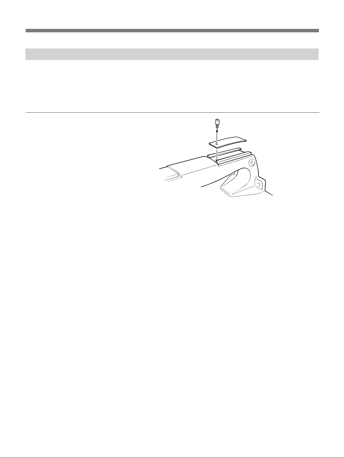
Accessory Attachment
Attaching a Videocassette Recorder
To attach an EVV-9000/9000P Hi8 Format
Videocassette Recorder to the camera head, follow the
procedures for attaching and detaching the CA-537/
537P Camera Adaptor.
1 Remove the screw of the
accessory shoe on the camera
head using a flat-head
screwdriver, and remove the
plate spring.
2 Attach the PVV-1/1P/1A/1AP/
3/3P following the procedures
for attaching the CA-537/537P.
To attach a Betacam format video cassette recorder
such as a PVV-1/1P/1A/1AP/3/3P, follow the
procedure below.
Refer to the EVV-9000/9000P and PVV-1/1P/1A/1AP/
3/3P operations manual for details.
Screw
Plate spring
24
 Loading...