


9100P-DXC
3-859-858-02(1)
3CCD Color Video Camera
Operating Instructions Page 2
Before operating this unit, please read this manual thoroughly and retain it for future reference.
Mode d’emploi Page 64
Avant d’utiliser cet appareil, lire attentivement ce mode d’emploi et le conserver pour toute référence ultérieure.
Bedienungsanleitung Seite 126
Lesen Sie dieses Handbuch bitte vor der ersten Inbetriebnahme der Kamera sorgfältig durch und bewahren Sie es zum späteren Nachschlagen griffbereit auf.
DXC-9100P
1997 by Sony Corporation

Owner’s Record
The model and serial numbers are located at the bottom. Record these numbers in the spaces provided below.
Refer to these numbers whenever you call upon your Sony dealer regarding this product.
Model No. DXC-9100P Serial No.
WARNING
To prevent fire or shock hazard, do not expose the unit to rain or moisture.
For the customers in the U.S.A.
This equipment has been tested and found to comply with the limits for a Class A digital device, pursuant to Part 15 of the FCC Rules. These limits are designed to provide reasonable protection against harmful interference when the equipment is operated in a commercial environment.
This equipment generates, uses, and can radiate radio frequency energy and, if not installed and used in accordance with the instruction manual, may cause harmful interference to radio communications. Operation of this equipment in a residential area is likely to cause harmful interference in which case the user will be required to correct the interference at his own expense.
You are cautioned that any changes or modifications not expressly approved in this manual could void your authority to operate this equipment.
This device requires shielded interface cables to comply with FCC emission limits.
2

Table of Contents
Chapter 1 Overview |
|
Features .............................................................................. |
5 |
Location and Functions of Parts and Controls ............... |
7 |
Front Panel/Top Panel/Bottom Panel ........................... |
7 |
Rear Panel ..................................................................... |
8 |
Chapter 2 Operation |
|
Adjusting and Setting with Menus ................................. |
11 |
Menu Configuration .................................................... |
11 |
Operation through Menus ........................................... |
13 |
Function of Menus ...................................................... |
15 |
Initial Setting List ....................................................... |
27 |
Shooting ............................................................................ |
28 |
Basic Shooting Procedure ........................................... |
28 |
Adjusting the White Balance ...................................... |
29 |
Using the Externally Triggered Shutter ...................... |
32 |
Capturing the Image into Memory by Using |
|
the Freeze Function ......................................... |
33 |
Setting the Scan Mode ................................................ |
35 |
Adjusting the Picture Tone in a Multi-Camera |
|
System ............................................................. |
37 |
Chapter 3 Installation and Connection
Installation ........................................................................ |
39 |
Mounting the Lens ...................................................... |
39 |
Mounting a Microscope Adaptor ................................ |
40 |
Mounting on a Tripod ................................................. |
40 |
Mounting to a Wall or Ceiling .................................... |
40 |
Basic System Connection ................................................ |
41 |
Connecting to Video Equipment With Composite |
|
Video Input Connectors ................................... |
42 |
Connecting to Video Equipment With RGB or |
|
S-Video Inputs ................................................. |
44 |
Connecting Two or More Cameras — Multi-Camera |
|
System ............................................................. |
45 |
Connecting to a Camera Control Unit |
|
(For Non-Medical Use) ................................... |
46 |
Connection to Enable Remote Control .......................... |
47 |
Connecting to the RM-C950 Remote Control Unit .... |
47 |
Remote Controlling the Camera from an External |
|
Pulse Signal ..................................................... |
50 |
Connecting to a Computer .......................................... |
51 |
Connection With a Printer/Digital Still Recorder ........ |
52 |
(Continued) |
|
English
3
Table of Contents
Chapter 4 Appendix |
|
Precautions ....................................................................... |
53 |
Safety Precautions ...................................................... |
54 |
Operating Precautions ................................................. |
57 |
Typical CCD Phenomena ................................................ |
58 |
Specifications .................................................................... |
59 |
Recommended Equipment .............................................. |
61 |
Symbol on the unit
Symbol |
|
Location |
This symbol indicates |
|
|
|
|
|
|
|
|
|
Rear panel |
This symbol indicates that a direct |
|
|
|||
|
|
|
|
current (DC) is input. |
|
|
|
|
|
|
|
|
Rear panel |
The connector that outputs RGB |
|
|
|
|
signals and their respective sync |
|
|
|
|
signals. |
|
|
|
|
|
|
|
|
Rear panel |
The connector that outputs the |
|
|
|
|
composite video signals. |
|
|
|
|
|
|
|
|
Rear panel |
The connector to which a remote |
|
|
|
|
control signal is input from a |
|
|
|
|
remote control unit. |
|
|
|
|
|
|
|
|
Rear panel |
The buttons for setting the |
|
|
|
|
automatic white balance. |
|
|
|
|
|
|
|
|
Rear panel |
The button for capturing the image |
|
|
|
|
in memory as a still image. |
|
|
|
|
|
4

Features
The DXC-9100P is a color video camera with an 1/2-inch, three-chip Progressive Scan CCD1).
The CCD uses an “all pixels read-out” method, which enables the CCD to output all pixel signals in 1/50 sec. This allows the unit to capture blur-free, clear images of fastmoving objects without a mechanical shutter.
High quality image
The DXC-9100P produces high quality images thanks to its 1/2inch, three-chip CCD containing some 460,000 effective picture elements (pixels). The camera has four features that ensure high image quality:
•High horizontal resolution: 800 TV lines
•High sensitivity (defined as minimum required illumination): 2,000 lux at F5.6
•High signal-to-noise ratio: 57 dB
•Low smear
Square pixels
The unit uses pixels which have the same pitch horizontally and vertically, namely 8.3µm × 8.3µm, to make a square pixel. Because the pixels are geometrically the same in both directions, you do not need to adjust the aspect ratio when using with a computer, image processor, etc. This function is very helpful when using the camera for image processing. This is also useful for image composition by inputting the signals to a computer.
N.I (non-interlaced) mode
An output of 50 frames of non-interlaced signals per seconds allows you to connect the unit to a multi-scan monitor or multi-scan printer which requires signals to be processed at high-speed.
However, connection with some multi-scan monitors may not be possible because of their input specifications. When in doubt, contact your authorized Sony dealer.
...........................................................................................................................................................................................................................................................
1) CCD: Charge-Coupled Device
5
Overview 1 Chapter

Features
Broad exposure control
Thanks to the AGC (Automatic Gain Control) and CCD iris control functions, the camera can handle a broad range of subject lighting conditions. When shooting in poor lighting conditions, the AGC feature automatically increases the sensitivity up to eight times. When the amount of light is excessive, the CCD iris control function automatically increases the shutter speed to cut exposure. This function can cut the exposure to the equivalent of up to 4 aperture stops. When using this camera in a fixed location, AGC, CCD iris control and auto-iris control allow for shooting in a broad range of lighting conditions. Combined use of AGC and CCD iris control is also very helpful when using the camera in a microscope system.
Wide range of electronic shutter modes
The wide range of speeds for the electronic shutter helps you overcome difficult shooting conditions, minimizes blurring in fast-moving subjects, and produces acceptably bright still images of subjects shot in poor light. The exposure time can be automatically controlled according to the brightness of the subjects. (For details, contact your authorized Sony dealer.)
Flickerless mode: When set to flickerless mode, the electronic shutter allows you to take flickerless images even under fluorescent light.
Clear scan mode: When you use the electronic shutter in the clear scan mode, you can shoot computer screen displays without horizontal stripes or distortion.
Externally-triggered shutter: The external trigger for the shutter enables a camera in a fixed location to capture flickerless images of fast-moving objects.
Freeze function
The moving image is captured in the frame memory built into this unit as a still image. The still image captured in the memory can be output continuously.
RS-232C interface
The unit can be controlled from an computer via an RS-232C interface.
Compact and lightweight
The unit is very compact (79 × 72 × 145 mm) and very light (about 790 g), allowing for easy installation in places where space is a problem.
The following are some examples of applications:
•As a camera for microscope
•As a roof-top weather monitoring camera
•As a laboratory monitor camera
•As a camera used in a video conference systems
6
Location and Functions of Parts and Controls
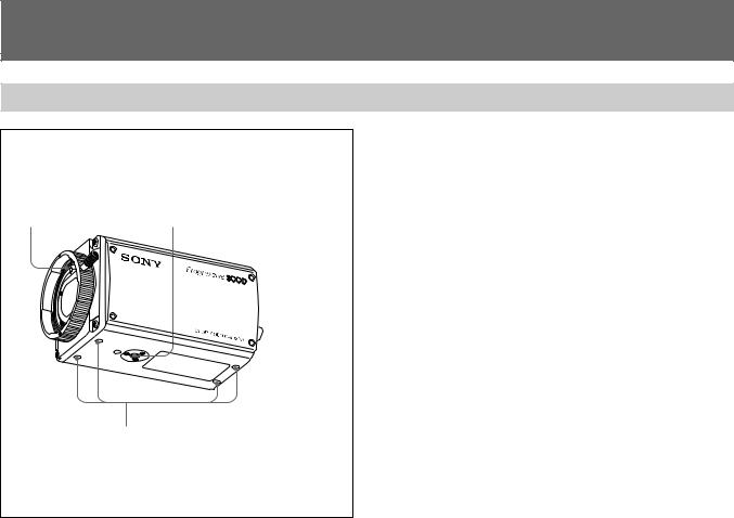
Front Panel/Top Panel/Bottom Panel
1 Lens Mount |
2 Installation/tripod holes |
|
(The top panel also has holes.) |
1 Lens Mount
Attach a zoom lens or micropscope adaptor.
2 Installation/tripod holes (top/bottom)
Use these holes when attaching the camera to a wall or ceiling or tripod (screw: 1/4", 20 ridges).
3 Camera fixing holes (top/bottom)
Use these holes (M3, depth of the hole:5 mm) to attach the camera to a wall or ceiling when you do not use the Installation/tripod holes2.
3 Camera fixing holes
(The top panel also has holes.)
7

Location and Functions of Parts and Controls
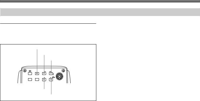
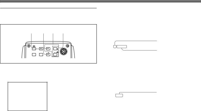
Rear Panel
1 |
VIDEO OUT connector |
|
|
||
2 |
RGB/SYNC connector |
|
|||
|
3 FREEZE button |
|
|
||
|
4 SOURCE button |
|
|||
|
5 BARS button |
|
|||
|
|
6 MENU button |
|
||
|
|
7 FUNCTION UP/DOWN buttons |
|||
|
|
|
8 DATA DOWN/SCAN button |
||
|
|
|
9 DATA UP/ |
WHITE |
|
|
|
|
|
button |
|
|
FREEZE |
MENU FUNCTION DATA |
LENS |
|
|
|
|
|
UP |
|
|
|
SOURCE |
BARS |
WHITE |
0 LENS |
|
|
DOWN |
|
|||
|
|
|
SCAN |
CCU |
connector |
|
RGB/SYNC |
|
|||
|
|
|
|||
|
|
|
|
||
|
|
|
|
|
!¡ CCU |
|
|
|
REMOTE |
|
connector |
|
VIDEO OUT |
|
|
|
|
|
|
DC IN/ |
|
EXT CTRL |
|
|
|
VBS |
|
|
|
|
|
|
|
|
|
|
|
|
|
|
!™ EXT |
|
|
|
|
|
CTRL |
|
|
|
|
|
connector |
|
|
|
!£ |
REMOTE connector |
|
!¢ |
DC IN/VBS |
connector |
|
||
1  VIDEO OUT (output) connector (BNC-type)
Outputs composite video signals.
2  RGB/SYNC (RGB/sync signal output) connector (D-sub 9-pin)
Outputs RGB signals and their respective sync signals. Use a CCXC-9DB/CCXC-9DD/CCMC-9DS cable for the connections.
Pin assignment
Pin No. |
Signal |
|
Pin No. |
Signal |
|
|
|
|
|
1 |
GND |
|
6 |
VBS/Y/VD output |
|
|
|
|
|
2 |
GND |
|
7 |
SYNC/WEN/HD output |
|
|
|
|
|
3 |
RED output |
|
8 |
GND |
|
|
|
|
|
4 |
GREEN output |
|
9 |
NC/C output |
5 |
BLUE output |
|
|
|
8

3  FREEZE button
Pressing this button stores an image in memory. The image is captured in memory as a still image at the instant when you press this button.
4 SOURCE button
Pressing this buttons clears freeze mode. The image which the unit is shooting appears on the monitor.
Note
The  FREEZE button 3 and SOURCE button 4 function when “FREEZE” on PAGE 3 menu is set to INT.CTRL.
For detailed information, see “PAGE 3 menu” on page 21 in “Function of Menus”.
5 BARS (color bars output) button
Pressing this button outputs the color bars signal. Press again to revert to video signal output.
For monitor adjustment, contact your authorized Sony dealer.
6 MENU (menu recall) button
Pressing this button brings up the operational settings menu on the monitor connected to the camera. Press again to hide the menu.
For menu operation, see “Adjusting and Setting with Menus” on page 11.
7 FUNCTION UP/DOWN (cursor up/down) buttons UP button: Moves the menu cursor upward.
DOWN button: Moves the menu cursor downward.
8DATA DOWN/SCAN (setting value reduction/scan mode select) button
With the menu displayed: decreases the setting value. With the menu hidden: activates the scan mode select
button. Each time you press the button, the scan mode changes in the order of NOR, F.S and N.I.
9 DATA UP/  WHITE (setting value increase/white balance adjustment) button
With the menu displayed: increases the setting value. With the menu hidden: activates the automatic white
balance adjustment function.
0 LENS connector (6-pin)
Connects to a lens cable when a 2/3-inch zoom lens is used. This connector is not used for 1/2-inch zoom lenses.
!¡ CCU (camera control unit) connector (20-pin)
Connects to the CCU-M5P camera control unit (not supplied)
9

Location and Functions of Parts and Controls
!™ EXT CTRL (external control signal input) connector
(BNC type)
Inputs the following signal according to the EXT. CTRL (BNC) setting on PAGE 3 menu.
When set to GENLOCK: Inputs reference sync signals for synchronizing the camera operation.
When set to TRIG.IN: Inputs pulses for controlling the memory or externally triggererd shutter.
!£  REMOTE (remote control) connector (mini-DIN
8-pin)
Connects to the RM-C950 remote control unit (not supplied).
!¢ DC IN/VBS  (DC power input/video signal output) connector (12-pin)
Connects to the CMA-D2CE/D2MDCE camera adaptor. Inputs the DC power and outputs the video signal.
10
Adjusting and Setting with Menus
Camera operational settings can be changed through simple adjustment of the settings on the on-screen menus. Settings can be adjusted to get the best possible results for the given shooting conditions or to enhance the image with special effects.
Menu Configuration
There are four menus.
To display the menu
Press the MENU button.
The menu is displayed on the monitor.
PAGE 1 menu
> PAGE 1 scan : NOR : A
GAI N |
STEP |
SHUTTER |
0dB |
OFF |
|
EXT. TR IGGER |
OFF |
AE W INDOW |
LARGE |
DETECT I ON |
AVERAGE |
> PAGE 4 scan : NOR |
: A |
USER PRESET |
A |
PROTECT |
OFF |
BAUD RATE |
9600 |
TR IGGER PULSE |
|
I R I S MODE |
AUTO |
AE LEVEL |
± 00 |
TR IGGER CYCLE |
OFF |
MENU SW |
OFF |
PAGE 2 menu
> PAGE 2 scan : NOR |
: A |
C. TEMP |
AUTO |
WHT. BAL |
AWB |
R Pa i nt |
± 00 |
B Pa i nt |
± 00 |
M. PEDESTAL |
± 00 |
GAMMA |
ON |
DETA I L |
ON |
LEVEL |
± 00 |
|
|
> PAGE 3 |
scan : NOR |
: A |
|
H. PHASE |
|
|
± 00 |
SC PHASE |
Rough |
0 |
|
|
F i ne |
|
± 00 |
G SYNC |
|
|
ON |
D–SUB V i deo |
|
Y / C |
|
D–SUB S ync |
C. SYNC |
||
EXT. CTRL (BNC) |
TR IG.I N |
||
FREEZE |
|
I NT. CTRL |
|
PAGE 4 menu |
PAGE 3 menu |
The menu page changes each time you press the DATA UP or DATA DOWN button.
11
Operation 2 Chapter

Adjusting and Setting with Menus
About on-screen menu
This section explains how to read the on-screen menu before starting menu operation.
1 |
|
|
4 |
|
2 |
> PAGE 1 scan : NOR : A |
5 |
||
|
GAI N |
STEP |
|
|
|
|
0dB |
|
|
3 |
SHUTTER |
OFF |
6 |
|
EXT. TR IGGER |
OFF |
|||
|
|
|||
|
AE W INDOW |
LARGE |
|
|
|
DETECT I ON |
AVERAGE |
|
|
|
|
|
|
|
|
|
|
|
|
1 Menu page
Displays the currently selected memory page.
Select the menu page using the DATA UP/DOWN buttons when the cursor is positioned on the menu page display.
2 Cursor
Selects an item. Move the cursor up/down using the FUNCTION UP/DOWN buttons.
3 Setting items
Scroll through the items to be set with the FUNCTION UP/ DOWN buttons.
4 SCAN mode
Indicates the currently selected scan mode.
For detailed information on the scan mode, see “Setting the Scan Mode” on page 35.
5 User preset
Indicates the currently selected user preset (A or B). When “PROTECT” is set to “ON”, a flashing “P” is displayed before the user preset A or B.
For details, see “PAGE 4 menu” on page 24.
6 Set values
Indicates the currently set value.
Change the values using the DATA UP/DOWN buttons.
12
Operation through Menus
Menu operation buttons
There are five buttons for menu operations on the rear panel of the unit.
MENU button
FUNCTION UP button
DATA UP button
FREEZE MENU FUNCTION DATA |
LENS |
UP |
SOURCE BARS |
WHITE |
DOWN |
|
|
SCAN |
FUNCTION DOWN button
VIDEO OUT |
REMOTE |
DC IN/ |
DATA DOWN button |
The following tables shows the functions of menu operation buttons.
Button |
Function |
|
|
MENU |
Displays the menu by pressing this button. To |
|
hide the menu, press the button again. |
|
|
FUNCTION UP |
Moves the cursor upward. |
|
|
FUNCTION DOWN |
Moves the cursor downward. |
|
|
DATA UP |
Increases the value. Changes the menu page. |
|
|
DATA DOWN |
Decreases the value. Changes the menu |
|
page. |
|
|
13
Adjusting and Setting with Menus
Menu operation procedure
To change the settings on the menu, proceed as follows.
1 3 2 4
FREEZE MENU FUNCTION DATA
 UP
UP  LENS
LENS
SOURCE BARS |
WHITE |
DOWN |
|
|
SCAN |
1 Press the MENU button.
The menu page that was selected last is displayed on the monitor screen.
> PAGE 1 scan : NOR : A
GAI N |
STEP |
|
0dB |
SHUTTER |
STEP |
SPEED |
1/125 |
EXT. TR IGGER |
OFF |
AE W INDOW |
MED IUM |
DETECT I ON |
PEAK |
2 Select the desired page.
1Move the cursor to the first line on the menu by pressing the FUNCTION UP button.
2Select the desired menu page by pressing the DATA UP or DOWN button.
|
|
Cursor |
|
> PAGE 1 scan : NOR : A |
|||
|
|||
GAI N |
STEP |
Menu page |
|
|
|||
SHUTTER |
0dB |
|
|
STEP |
|
||
SPEED |
1/125 |
|
|
EXT. TR IGGER |
OFF |
|
|
AE W INDOW |
MED IUM |
|
|
DETECT I ON |
PEAK |
|
|
|
|
|
|
3 Move the cursor to the item to be set by pressing the FUNCTION UP or DOWN button.
PAGE 1 scan : NOR : A |
Setting item |
||
>GAI N |
STEP |
||
|
|||
|
0dB |
|
|
SHUTTER |
STEP |
|
|
SPEED |
1/25 |
|
|
EXT. TR IGGER |
OFF |
|
|
AE W INDOW |
MED IUM |
|
|
DETECT I ON |
PEAK |
|
|
|
|
|
|
14
4 Change the value by pressing the DATA UP or DOWN button.
PAGE 1 scan : NOR : A
>GAI N |
STEP |
|
Set value |
|
0dB |
|
|
|
|
||
SHUTTER |
STEP |
|
|
SPEED |
1/125 |
|
|
EXT. TR IGGER |
ON |
|
|
AE W INDOW |
MED IUM |
|
|
DETECT I ON |
PEAK |
|
|
To return to the regular monitor screen
Press the MENU button.
Function of Menus
PAGE 1 menu
This section describes in detail items on PAGE 1 menu.
> PAGE 1 scan : NOR : A
GAI N |
STEP |
|
0dB |
SHUTTER |
OFF |
EXT. TR IGGER |
OFF |
AE W INDOW |
LARGE |
DETECT I ON |
AVERAGE |
The following table shows the PAGE 1 menu items, their contents and reference pages in this manual.
Item |
Contents of setting |
Ref. page |
|
|
|
GAIN |
Adjusts video gain. |
15 |
|
|
|
SHUTTERa) |
Sets the electronic shutter. |
16 |
EXT.TRIGGER |
Sets the external trigger for the |
18 |
|
shutter to ON or OFF. |
|
|
|
|
AE WINDOW |
Selects the AE window when in the |
18 |
|
AGC, CCD IRIS or AUTO IRIS mode. |
|
|
|
|
DETECTION |
Selects the detection method of the |
18 |
|
luminance level for the selected AE |
|
|
WINDOW. |
|
|
|
|
a)When “SHUTTER” is set to STEP or VARIABLE, “SPEED” appears and you can set the shutter speed.
GAIN
Adjusts the video gain.
Selection |
Function |
|
|
AGC |
Automatic gain control. Automatically adjusts the gain |
|
of the video signal to match the brightness of the |
|
subject. This function is useful for shooting subjects |
|
under changing ighting conditions. |
|
|
STEP |
Sets the video gain to manual control. Use this function |
|
for shooting in extremely dark places where even fully |
|
opening the lens iris still does not produce an |
|
acceptably bright image. The gain level can be set in |
|
the range of 0 to 18 dB in units of 1 dB. |
|
|
15

Adjusting and Setting with Menus
SHUTTER
The electronic shutter allows for blur-free images of fastmoving subjects and produces good still images of subjects shot in poor lighting conditions.
Selection |
Function |
OFF |
Deactivates the electronic shutter. |
|
|
STEP |
Sets the shutter speed to any of 9 steps in high-speed |
|
shutter mode and 15 steps in long-exposure mode. |
|
High-speed mode: 1/50, FL (flickerless), 1/125, |
|
1/250, 1/500, 1/1000, 1/2000, 1/4000 and 1/10000 |
|
seconds |
|
Long-exposure mode: 0.1, 0.2, 0.3, 0.5, 1.0, 1.5, |
|
2.0, 2.5, 3.0, 3.5, 4.0, 5.0, 6.0, 7.0 and 8.0 sec. |
To set the shutter speed
1Display 1/50 (factory-set value) by pressing the DATA UP and DATA DOWN button together.
2Select the desired shutter speed by pressing the DATA UP or DOWN button.
On pressing the UP button: The shutter speed changes in the order 1/50, FL (flickerless),
1/125,1/250, 1/500, 1/1000, 1/2000, 1/4000 and 1/10000 each time you press the UP button.
On pressing the DOWN button: The shutter speed changes in the order 0.1, 0.2, 0.3, 0.5, 1.0, 1.5, 2.0, 2.5, 3.0, 3.5, 4.0, 5.0, 6.0, 7.0 and 8.0 sec.
When using the unit with 60 Hz lighting, setting the shutter to FL gives you flickerless images even under fluorescent light.
Selection Function
VARIABLE Use for fine adjustment of the video output level. You can adjust the shutter speed in long exposure mode or clear scan mode.
In long exposure mode
You can set the shutter speed in units of 1 frame. For example, if the value is set to 50 frames (about 2.0 seconds in the PAL format), the total video signal produced during this set time is output in the form of
one complete frame at intervals of about 2.0 seconds. These pictures, which contain 50 frames of video information, are much brighter than normal one-frame images. This mode of setting the shutter speed is very useful for shooting a poorly illuminated subject in a dark place.
1Display 312/625 (factory-set value) by pressing the DATA UP and DATA DOWN button together.
2Select the desired shutter speed by pressing the DATA DOWN button.
Each time you press the DATA DOWN button, the shutter speed changes in units of 1 frame from 1 FRM through 255 FRM.
Shutter speed calculation
Example: Shutter speed when the unit is set at 5 frames
5 × 1/25 = 0.20 seconds
Note
In long exposure mode, AUTO IRIS cannot be used.
16

Selection Function
VARIABLE In clear scan mode
(Continued) You can set the shutter speed in units of 1 H (horizontal scanning time: 64µs). The setting is made in units of 1H. This setting can be used to reduce noise (horizontal patterns) when shooting a computer screen.
1Display 312/625 by pressing the DATA UP and DATA DOWN button together.
2Select the setting which best reduces reduce the noise by pressing the DATA UP button while observing the noise on a monitor screen.
Each time you press the DATA UP button, the shutter speed changes in units of 1 H from 312/625 through 1/625.
Shutter speed calculation
Example: Shutter speed in 250/625 (H) 250 x 64 µs (1H) + 35.6 µs (constant) = 16035.6 µs = about 0.016 seconds.
Selection Function
CCD IRIS When an excessive amount of light passes through the lens, this function increases shutter speed to cut exposure to the equivalent of up to 4 aperture stops. The function is useful for microscope applications where lighting that is just right for the human eye is often too bright for the video camera.
When CCD-IRIS is set to ON, the excessive incident light is automatically decreased to an appropriate level for the video camera. The CCD iris function is also useful for cutting out excess incident light that is not cut out by the auto-iris lens in scenes containing very bright patches (such as snow, or sea water reflecting sunlight).
You can use CCD IRIS in combination with AGC, and/ or AUTO IRIS control.
17

Adjusting and Setting with Menus
EXT. TRIGGER
Enables and disables the external trigger for the shutter.
Selection |
Function |
|
|
ON |
Enables the external trigger for the shutter. |
|
|
OFF |
Disables the external trigger for the shutter. |
|
Normally set this item to OFF. |
AE WINDOW
Selects the AE (auto exposure) when the unit is used with the following setting.
•AGC (automatic gain control)
•CCD IRIS of SHUTTER
•Using the auto-iris lens
When shooting very small subjects, the point you want to see become bright if you set “AE WINDOW” to “SPOT”. When you bring the cursor to AE WINDOW, the currently selected AE window appears on the monitor. Each time you press the DATA UP or DATA DOWN button, the AE window changes.
AE windows
DETECTION
Selects the detection method of the luminance level of the selected AE window.
Selection Function
AVERAGE Select to see the whole AE window.
PEAK |
Select to see the part with the highest video level in |
|
the AE window. |
|
|
|
|
|
|
|
|
|
|
|
|
|
|
|
|
|
|
|
|
|
|
|
|
|
|
|
|
|
|
|
|
|
|
|
|
|
|
|
|
|
|
|
|
|
|
|
|
|
|
|
|
|
|
|
|
|
|
|
|
|
|
|
|
|
|
|
|
|
|
|
|
|
|
|
|
|
|
Large |
|
|
Medium |
|
Spot |
||||
18

PAGE 2 menu
This section describes in detail items on PAGE 2 menu.
|
|
|
|
|
> PAGE 2 scan : NOR |
: A |
|
|
C. TEMP |
AUTO |
|
|
WHT. BAL |
AWB |
|
|
R Pa i nt |
± 00 |
|
|
B Pa i nt |
± 00 |
|
|
M. PEDESTAL |
± 00 |
|
|
GAMMA |
ON |
|
|
DETA I L |
ON |
|
|
LEVEL |
± 00 |
|
|
|
|
|
|
|
|
|
The following table shows the PAGE 2 menu items, their contents and reference pages in this manual.
Item |
Contents of setting |
Ref. page |
|
|
|
C.TEMP |
Selects the color temperature |
19 |
according to the |
lighting condition. |
|
|
|
|
WHIT.BAL |
Selects the white balance settings. |
19 |
|
|
|
M.PEDESTAL |
Sets the pedestal level of the output |
20 |
|
signal. |
|
|
|
|
GAMMA |
Gamma compensation (on/off). |
20 |
|
|
|
DETAIL |
Enables and disables the DETAIL |
20 |
|
function (on/off). |
|
|
|
|
LEVELa) |
Adjusts the sharpness of the object |
21 |
|
outline. |
|
|
|
|
a) This item appears when DETAIL is set to ON.
C. TEMP
Selects the color temperature according to the lighting.
Selection |
Lighting condition |
|
|
|
|
AUTO |
Use for automatic adjustment of the color |
|
temperature with “WHIT.BAL” set to “AWB”. |
||
|
||
|
|
|
3200K |
Use for indoor shooting. |
|
|
|
|
5600K |
Use for outdoor shooting. |
|
|
|
WHIT.BAL
Selects the white balance settings.
Selection |
Function |
|
|
AWB |
Use for automatic adjustment of the white balance. |
|
For details, see “Adjusting the White Balance.” |
|
For details of how to make fine adjustment using “R Paint” |
|
and “B Paint”, see the following ATW. |
|
|
MANU |
Use for manual adjustment of white balance. Both red |
|
gain (R gain) and blue gain (B gain) are adjustable. |
|
R Gain: Adjusts the red gain (-127 to +127) |
|
B gain: Adjusts the blue gain (-127 to +127) |
|
Ptress the DATA UP and DATA DOWN buttons |
|
together, to reset the values to ±000. |
|
|
|
(Continued) |
19

Adjusting and Setting with Menus
Selection Function
ATW Activates auto-tracing white balance. This mode is suitable for when the light source changes. The white balance is automatically adjusted as the color temperature changes.
When WHIT.BAL is set to AWB or ATW, the “R Paint” and “B Paint” values are displayed on the menu. Use these for fine adjustment. Adjust these while looking at the screen.
R Paint: Adjusts the red paint (-10 to +10) B Paint: Adjusts the blue paint (-10 to +10)
Press the DATA UP and DATA DOWN buttons together to reset the values ±00.
M. PEDESTAL
Normally set to ±00.
Adjusts the darkness level of the black part of the image. Use this function to bring out details in heavily shaded areas. Use of a waveform monitor will make the adjustment easier.
The pedestal levels of the R, G, B output signals can be adjusted simultaneously within the range from -99 to +99.
Adjusting direction |
Outline of the image |
|
|
+ |
Lighter |
− |
Darker |
Press the DATA UP and DATA DOWN buttons together to reset the values to ±00.
GAMMA
Gamma compensation.
Selection |
Function |
|
|
ON |
Compensates the reproduction characteristics of the |
|
screen to produce natural-tone images. Use this |
|
setting for normal camera use. |
|
|
OFF |
Outputs the video signal linearly from the CCD without |
|
gamma compensation. Use this setting when you |
|
want to produce images for image processing or |
|
image analysis. |
|
|
DETAIL
Enables and disabales adjustment of the sharpness of the object outlines.
Selection |
Function |
|
|
ON |
Adjustment of the sharpness of the object outlines |
|
disabled. |
|
|
OFF |
Does not enable the adjustment of the sharpness of |
|
the object outlines. |
|
|
20
LEVEL
This item appears when “DETAIL” is set to “ON”. Adjusts the sharpness of the subject outlines within the range from -99 to +99, when DETAIL is set to ON.
Adjusting direction |
Outline of the image |
|
|
+ |
Sharper with more detail on the image |
|
outline. |
− |
Softener with less detail. |
By pressing the DATA UP and DATA DOWN buttons together, the values are reset to ±00
PAGE 3 menu
This section describes in detail items on PAGE 3 menu.
|
|
|
|
|
|
|
> PAGE 3 |
scan : NOR |
: A |
|
|
|
H. PHASE |
|
|
± 00 |
|
|
SC PHASE |
Rough |
0 |
|
|
|
|
F i ne |
|
± 00 |
|
|
G SYNC |
|
|
ON |
|
|
D–SUB V i deo |
|
Y / C |
|
|
|
D–SUB S ync |
C. SYNC |
|
||
|
EXT. CTRL (BNC) |
TR I G.I N |
|
||
|
FREEZE |
|
I NT. CTRL |
|
|
|
|
|
|
|
|
|
|
|
|
|
|
The following tables shows the PAGE 3 menu items, their contents and reference pages.
Item |
Content of settings |
Ref. page |
|
|
|
H.PHASE |
Adjusts the difference in phase |
22 |
SC PHASE |
between the subcarrier and |
|
|
horizontal synchronization during |
|
|
external synchronization. |
|
|
|
|
G SYNC |
Adds a sync signal to the G (green) |
22 |
|
channel of the RGB output. |
|
|
|
|
D-SUB Video |
Outputs the video signal from the |
22 |
|
RGB/SYNC (D-sub) |
|
|
connector. |
|
|
|
|
D-SUB Sync |
Outputs sync signal from the |
23 |
|
RGB/SYNC (D-sub) |
|
|
connector. |
|
|
|
|
EXT.CTRL (BNC) |
Selects the EXT CTRL signal input |
23 |
|
(sync signal/external pulse signal) |
|
|
|
|
FREEZE |
Selects how to capture the image |
23 |
|
into memory (external pulse signal/ |
|
|
FREEZE button on the rear |
|
|
panel). |
|
|
|
|
MODEa) |
Selects the memory mode (F/F or |
23 |
|
F/S) |
|
|
|
|
a) This item appears when “FREEZE” is set to “EXT.CTRL”.
21

Adjusting and Setting with Menus
H.PHASE
When an external reference sync signal for locking the camera sync generator is input to the EXT CTRL connector on the rear panel, the camera operates at the frequency of the reference signal. You can use the H. PHASE function to perfectly synchronize the camera operation with the reference signal to the level of the horizontal phase.
You can adjust the level within the range from -99 to +99. Press the DATA UP and DATA DOWN buttons together to reset the values to ±00.
Notes
•To perform this adjustment, set “EXT.CTRL (BNC)” to “GENLOCK”. If you set “EXT.CTRL (BNC)” to “TRIG.IN”, no value is displayed.
•When an external reference signal is not input to the EXT CTRL connector, you cannot change the set value.
SC PHASE
When locking the camera sync generator, use the SC PHASE function to adjust the subcarrier phase.
Selection |
Function |
|
|
SC PHASE Rough |
Rough adjustment by setting to between 0° |
|
and 180°. |
SC PHASE Fine |
Fine adjustment by adjusting the level within |
|
the range from -99 to +99. |
|
|
Press the DATA UP and DATA DOWN buttons together to reset the values to ±00.
Notes
•To perform this adjustment, set “EXT.CTRL (BNC)” to “GENLOCK”. If you set “EXT.CTRL (BNC)” to “TRIG.IN”, no value is displayed.
•When an external reference signal is not input to the EXT CTRL connector, you cannot change the set value.
G SYNC
Adds a sync signal to the G signal in the RGB output.
Selection |
Function |
|
|
|
|
ON |
Select when using a video monitor without a sync |
|
|
input connector. A sync-added G signal can be output |
|
|
form the |
RGB/SYNC connector. |
|
|
|
OFF |
A sync signal is not added to the G output signal. |
|
|
|
|
D-SUB Video
Selects the output signal of  RGB/SYNC connector (D-sub 9-pin).
Selection |
Output signal |
|
|
VBS |
VBS signal |
|
|
YC |
YC signal |
|
|
VD |
VD signal .The VD signal is automatically selected |
|
when “D-SUB Sync” is set to “HD”. |
|
|
22

D-SUB Sync
Selects the output sync signal of  RGB/SYNC connector (D-sub 9-pin).
|
Selection |
Output sync signal |
||
|
|
|
||
|
C.SYNC |
Composite SYNC signal |
||
|
|
|
||
|
WEN |
WEN signal. The WEN signal is output to peripheral |
||
|
|
equipment as a trigger pulse. |
||
|
|
|
|
|
|
|
|
Note |
|
|
|
Connect the camera to peripheral equipment after |
||
|
|
completing all of menu settings. |
||
|
|
|
||
|
HD |
HD signal. When HD is selected, “D-SUB Video” is |
||
|
|
automatically set to “VD”. |
||
|
|
|
|
|
EXT. CTRL (BNC)
Selects the input signal to the EXT CTRL connector on the rear panel.
Selection |
Input signal |
|
|
TRIG.IN |
Control signal for the built-in memory and external |
|
trigger shutter. |
|
|
GENLOCK |
Sync signal for synchronizing the camera operation |
|
with the reference signal. |
|
|
FREEZE
Selects the control signal for capturing the image to the built-in memory.
Selection |
Control signal |
|
|
|
|
INT.CTRL |
Enables the |
FREEZE button on the rear panel to |
|
capture the image to the built-in memory. |
|
|
|
|
EXT.CTRL |
The external pulse signal is used to capture the image |
|
|
to the built-in memory. |
|
|
|
|
MODE
This item appears when “FREEZE” is set to “EXT.CTRL”. Selects how to control the unit using the external pulse.
Selection |
Control method |
|
|
F/F |
Whenever an external pulse is input, the image is |
|
captured to memory, replacing the previously |
|
captured image. |
|
|
F/S |
When an external pulse is input, the image is captured |
|
to memory replacing the previously captured image, |
|
and the captured image is output as a still image. |
|
When the next external pulse signal is input, the live |
|
image shot with the camera is output. These |
|
operations are repeated cyclically whenever external |
|
pulses are input. |
|
|
23

Adjusting and Setting with Menus
PAGE 4 menu
This section describes in detail items on PAGE 4 menu.
|
|
|
|
|
> PAGE 4 scan : NOR |
: A |
|
|
USER PRESET |
A |
|
|
PROTECT |
OFF |
|
|
BAUD RATE |
9600 |
|
|
TR IGGER PULSE |
|
|
|
I R I S MODE |
AUTO |
|
|
AE LEVEL |
± 00 |
|
|
TR IGGER CYCLE |
OFF |
|
|
MENU SW |
OFF |
|
|
|
|
|
|
|
|
|
The following tables shows the PAGE 4 menu items, their contents and reference pages.
Item |
Content of settings |
Ref. page |
|
|
|
USER PRESET |
Selects the user preset A or B. |
24 |
|
|
|
PROTECT |
Protects the user preset. |
25 |
|
|
|
BAUD RATE |
Selects the baud rate. |
25 |
|
|
|
TRIGGER PULSE |
Selects the polarity of the input |
25 |
|
pulse. |
|
|
|
|
IRIS MODE |
Selects the iris mode (auto/fixed) |
25 |
|
|
|
AE LEVELa) |
Finely adjusts the focusing point of |
25 |
|
AE. |
|
|
|
|
TRIGGER CYCLE |
Selects the cycle of the internal |
26 |
|
trigger pulse. |
|
|
|
|
MENU SW |
Selects how to change the user |
26 |
|
preset (on the menu/using the |
|
|
FUNCTION UP button). |
|
a) This item appears when IRIS MODE is set to AUTO.
USER PRESET
You can create up to two sets of menu settings for the camera, and save these settings as a user preset. You can switch to the set which is most suitable for the shooting condition at hand. The currrently active user set is shown in the upper left corner of the menu.
24

PROTECT
You can protect the current user settings by setting “PROTECT” to “ON.”
To save user sets and protect them
1 Select user preset A or B as desired from “USER PRESET”.
2 Make any settings or adjustments using the PAGE 1 to PAGE 4 menus.
3 Set “PROTECT” to “ON.”
The flashing “P” appears in front of the displayed user preset A or B. This indicates that the user preset is protected.
Note that the following item can be changed even when a user preset is protected.
•USER PRESET
•PROTECT
BAUD RATE
Changes the baud rate of the REMOTE connector to any of 9600, 4800, 2400 or 1200.
Use a baud rate of 9600 when an RM-C950 is connected.
TRIGGER PULSE
Selects the same polarity as the input signal for controlling the memory or external trigger shutter.
Selection Polarity
Falling edge
Rising edge
IRIS MODE
Sets the iris mode.
Selection |
Function |
|
|
AUTO |
To use the auto iris lens. |
|
|
FIX |
To use the optical lens without the auto iris |
|
function. |
AE LEVEL
This item appears when IRIS MODE is set to AUTO.
The auto exposure focusing level can be adjusted within the range from -31 to +31 by pressing the DATA UP or DATA DOWN button.
Press the DATA UP and DATA DOWN buttons together to reset the values to ±00.
25

Adjusting and Setting with Menus
TRIGGER CYCLE
Sets the cycle for the the built-in memory to be controlled by the internal pulse.
Selection |
Function |
OFF |
The built-in memory is controlled by an external |
|
pulse. |
2-FRM to 10 min Sets the cycle of the internal pulse within the range from 2-FRM to 10 min.
MENU SW
Selects whether to switch the user preset A and B by using the FUNCTION UP button on the rear panel without the menu displayed.
Selection |
Function |
|
|
OFF |
Disables the FUNCTION UP button to switch between |
|
the user presets. |
|
|
ON |
Enables the FUNCTION UP button to switch between |
|
user presets. |
|
When you press the FUNCTION UP button, the user |
|
preset is switched instantaneously. |
|
|
For example, if user preset A is selected when the “MENU SW” is set to ON, pressing the FUNCTION UP button switches to user preset B after returning to the regular screen.
Note
When you switch between user presets with the FUNCTION UP button, the currently selected user preset name is not displayed on the monitor.
26
Initial Setting List
MENU PAGE |
Item |
Initial setting |
|
|
|
PAGE 1 |
GAIN |
STEP:0 dB |
|
|
|
|
SHUTTER |
OFF |
|
|
|
|
SPEEDa) |
STEP:1/50 |
|
|
VARIABLE:312/625 |
|
|
|
|
EXT.TRIGGER |
OFF |
|
|
|
|
AE WINDOW |
LARGE |
|
|
|
|
DETECTION |
AVERAGE |
|
|
|
PAGE 2 |
C.TEMP |
AUTO |
|
|
|
|
WHT.BAL |
AWB |
|
|
|
|
|
R Paint:±00 |
|
|
B Paint:±00 |
|
|
R Gain:±000 |
|
|
B Gain:±000 |
|
|
|
|
M.PEDESTAL |
±00 |
|
|
|
|
GAMMA |
ON |
|
|
|
|
DETAIL |
ON |
|
|
|
|
LEVELb) |
±00 |
a)“SPEED” appears when “SHUTTER” is set to “STEP” or “VARIABLE”.
b)“LEVEL” appears when “DETAIL” is set to “ON”.
MENU PAGE |
Item |
Initial setting |
PAGE 3 |
H.PHASE |
±00 |
|
SC PHASE Rough |
0 |
|
SC PHASE Fine |
±00 |
|
G SYNC |
ON |
|
D-SUB Video |
Y/C |
|
D-SUB Sync |
C.SYNC |
|
EXT.CTRL(BNC) |
TRIG.IN |
|
FREEZE |
INT.CTRL |
|
MODEc) |
F/S |
PAGE 4 |
USER PRESET |
A |
|
PROTECT |
OFF |
|
BAUD RATE |
9600 |
|
TRIGGER PULSE |
|
|
IRIS MODE |
AUTO |
|
AE LEVELd) |
±00 |
|
TRIGGER CYCLE |
OFF |
|
MENU SW |
OFF |
c)“MODE” appears when “FREEZE” is set to “EXT. CTRL”.
d)“AE LEVEL” appears when “IRIS MODE” is set to “AUTO”.
27
Shooting
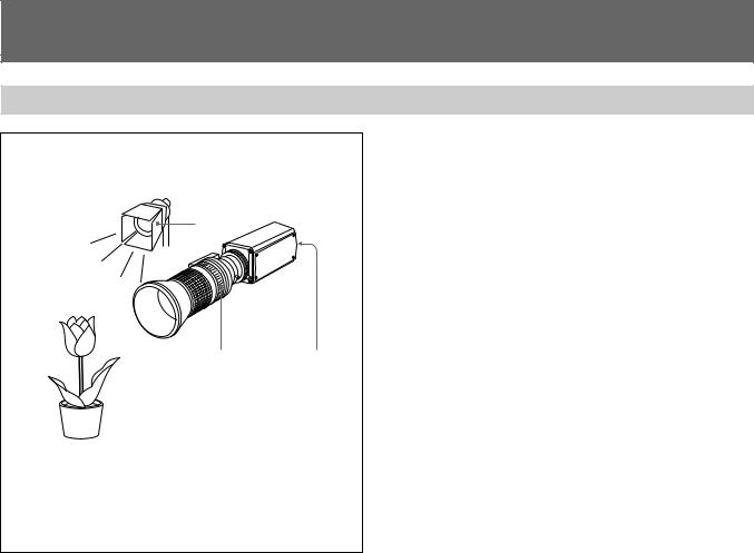
Basic Shooting Procedure
|
1 |
Turn on the power of the camera and all connected |
|
|
devices. |
|
2 |
Illuminate the subject with proper lighting. |
2 |
3 |
Aim the camera and adjust the iris, focus and zoom. |
|
4 |
Adjust the white balance. |
|
|
For more details, see “Adjusting the White Balance” on page |
|
|
29. |
|
5 |
Adjust the settings as needed. |
3 |
4, 5 |
For more details, see “Adjusting and Setting with Menus” on |
page 11. |
||
|
6 |
Start shooting. |
28
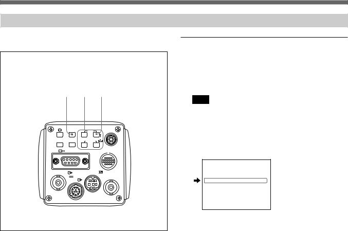
Adjusting the White Balance
Each time the lighting conditions change, adjust the white balance so that optimal color reproduction is obtained.
1, 3 |
2 |
7 |
FREEZE MENU FUNCTION DATA |
LENS |
||
|
|
UP |
|
SOURCE |
BARS |
WHITE |
|
DOWN |
|
||
|
|
|
|
RGB/SYNC |
SCAN |
|
|
|
|
||
VIDEO OUT |
|
REMOTE |
|
|
DC IN/ |
|
EXT CTRL |
VBS
Operation procedure
1 Press the MENU button to display the menu.
2 Select the PAGE 2 menu and set “WHT.BAL” to “AWB”.
Note
Check that “PROTECT” on PAGE 4 menu is set to “OFF”. If set to “ON”, you cannot change “WHT.BAL” to “AWB”.
For more details, see “PROTECT” of “PAGE 4 menu” on page 25.
For details of how to operate, see “Operation through Menus” on page 13.
PAGE 2 scan : NOR : A
C. TEMP |
AUTO |
>WHT. BAL |
AWB |
R Pa i nt |
± 00 |
B Pa i nt |
± 00 |
M. PEDESTAL |
± 00 |
GAMMA |
ON |
DETA I L |
OFF |
3 Press the MENU button to make the menu disappear.
(Continued)
29
Shooting
4 Display the camera image on the screen.
Note
If the color bar signal is displayed on the screen, press the BAR button to make it disappear.
5 Set the lens iris control as follows.
When using an auto-iris lens: Set to auto-iris control. When using a manual-iris lens: Set to an appropriate
iris opening value.
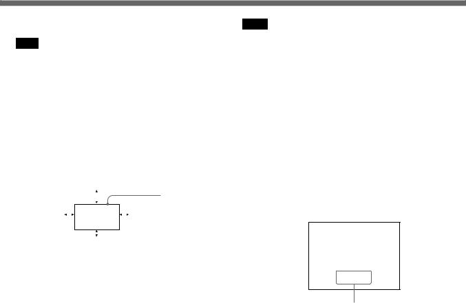
6 Place a white object in the same light as that falling on the subject to be shot, then zoom in on the object to fill the screen as follows.
|
20% of screen height |
|
||||||||
|
|
|
|
|
|
|
|
|
|
The white object |
|
|
|
|
|
|
|
|
|
|
|
15% of |
|
|
|
|
|
|
|
|
15% of |
must fill a |
|
|
|
|
|
|
|
|
|||
|
|
|
|
|
|
|
|
rectangle of this |
||
screen width |
|
|
|
|
|
|
|
|
screen |
|
|
|
|
|
|
|
|
|
|||
|
|
|
|
|
|
|
|
size. (Avoid very |
||
|
|
|
|
|
|
|
|
|
width |
|
|
|
|
|
|
|
|
|
|
bright highlights |
|
|
|
|
|
|
|
|
|
|
|
|
|
|
|
|
|
|
|
|
|
|
within the |
|
|
|
|
|
|
|
|
|
|
|
|
10% of screen height |
rectangle.) |
||||||||
The white object can be a piece of white paper or cloth, a white wall, or the like.
Notes
•Not to include highly reflective items in the picture.
•Always shoot the image under suitable lighting conditions.
7 Press the · WHITE button.
The message “WHITE OK” appears on the screen when the adjustment is done.
The adjusted white level is automatically stored in memory and remains, even if the camera’s power is turned off.
To shoot under the same condition, the stored white balance is reproduced with the “WHIT.BAL” set to “AWB”.
White balance adjustment errors
If the white balance adjustment is not successful, an error message appears on the screen. If this happens, take the necessary measures and conduct steps 1 through 7 again.
For more details, see “Error messages” on page 31.
WH I TE NG
L EVEL LOW
Error message
30
 Loading...