


 Loading...
Sony DVS-V6464B, DVS-RS1616, BKS-R3202, BKS-R1601, DVS-128 User Manual
...ROUTING SWITCHER SYSTEM
ROUTING SWITCHER |
RS-422A REMOTE ROUTING SWITCHER |
DVS-128 |
DVS-RS1616 |
DIGITAL AUDIO ROUTING SWITCHER |
TIME CODE ROUTING SWITCHER |
DVS-A3232 |
DVS-TC3232 |
DIGITAL VIDEO ROUTING SWITCHER |
ANALOG AUDIO ROUTING SWITCHER |
DVS-V1616 |
BVS-A3232 |
HD ROUTING SWITCHER |
ANALOG VIDEO ROUTING SWITCHER |
HDS-V3232 |
BVS-V3232 |
DIGITAL VIDEO ROUTING SWITCHER
DVS-V3232B/V3232M
DVS-V6464B/V6464M
MULTI BIT RATE ROUTING SWITCHER
HDS-X3400/X3600/X3700
16-SOURCE CONTROL UNIT |
MULTI DISPLAY CONTROL UNIT |
BKS-R1601 |
BKS-R1607/R1617/R1621 |
X-Y CONTROL UNIT |
MULTI BUS CONTROL UNIT |
BKS-R3202/R3210/R3220 |
BKS-R3216 |
32-SOURCE CONTROL UNIT |
ROUTING SWITCHER CONTROLLER |
BKS-R3203 |
BKPF-R70/R70A |
UNIVERSAL CONTROL UNIT |
DIGITAL VIDEO 8 x2 SELECTOR BOARD |
BKS-R3204/R1608/R3209 |
BKPF-300 |
BKS-R1618/R3219 |
ANALOG VIDEO 8 x2 SELECTOR BOARD |
SOURCE AND DESTINATION CONTROL UNIT |
BKPF-301 |
BKS-R3205 |
DIGITAL AUDIO 8 x2 SELECTOR BOARD |
8-DESTINATION CONTROL UNIT |
BKPF-350 |
BKS-R3206 |
ANALOG AUDIO 8 x2 SELECTOR BOARD |
|
BKPF-351 |
INSTALLATION MANUAL FOR SYSTEM SETUP 1st Edition (Revised 5)
IBM and AT are registered trademarks of International Business Machines, Inc. Windows is a registered trademark of Microsoft Corporation.
Windows NT is a trademark of Microsoft Corporation. Intel 80486SX is a trademark of Intel Corporation.
ROUTING SWITCHER SYSTEM (E)
Table of Contents
Manual Structure
Purpose of this manual .............................................................................................. |
5 |
Contents ..................................................................................................................... |
5 |
Related manuals ......................................................................................................... |
6 |
DVS-128/HDS-X3000 Series and DVS-V3232M/V6464M ..................................... |
8 |
1. |
System Overview |
|
|
1-1. |
Digital Routing Switcher System ................................................................ |
1-1 |
|
1-2. |
System Control ............................................................................................ |
1-3 |
|
|
1-2-1. Specifications and functions of control port .............................. |
1-3 |
|
|
1-2-2. |
S-BUS control ............................................................................ |
1-5 |
|
1-2-3. |
9-pin remote control ................................................................... |
1-7 |
|
1-2-4. |
Connection of control terminal .................................................. |
1-9 |
|
1-2-5. |
Control of monitor S-BUS system ............................................. |
1-9 |
2. Functions
2-1. |
Main Functions of Router System ............................................................... |
2-1 |
2-2. |
Built-in Controller ....................................................................................... |
2-2 |
2-3. |
Matrix Sizes ................................................................................................ |
2-2 |
2-4. |
Number of Levels ........................................................................................ |
2-2 |
2-5. |
Number of Units .......................................................................................... |
2-2 |
2-6. |
Protect Function .......................................................................................... |
2-3 |
2-7. |
Secret Function ............................................................................................ |
2-3 |
2-8. |
Crosspoint Disable Setting Function |
|
|
(DVS-V3232B/V6464B, BKPF-R70 and HDS-V3232) ............................. |
2-3 |
2-9. |
Password Function (DVS-V3232B/V6464B, BKPF-R70, HDS-V3232) ... |
2-3 |
2-10. |
Setting the Input/Output Name |
|
|
(DVS-V3232B/V6464B, BKPF-R70 and HDS-V3232) ............................. |
2-4 |
2-11. |
Virtual Mapping Function |
|
|
(DVS-V3232B/V6464B, BKPF-R70 and HDS-V3232) ............................. |
2-6 |
2-12. |
Free Assignment Function |
|
|
(DVS-V3232B/V6464B, BKPF-R70 and HDS-V3232) ............................. |
2-7 |
2-13. |
Monitor Function (BKDS-V3292B only) ................................................... |
2-8 |
2-14. |
Tie Line Management |
|
|
(DVS-V3232B/V6464B, BKPF-R70 and HDS-V3232) ........................... |
2-10 |
2-15. |
Phantom Function ..................................................................................... |
2-11 |
2-16. |
Self-Diagnosis Function ............................................................................ |
2-12 |
2-17. |
Route Function .......................................................................................... |
2-13 |
2-18. |
Enhanced Restriction of Selected Block (BKS-R1607/R3210 only) ........ |
2-14 |
ROUTING SWITCHER SYSTEM (E) |
1 |
3. |
Control Terminal |
|
|
3-1. Selecting the Control Terminal ................................................................... |
3-1 |
||
3-2. |
Control Terminal Display ........................................................................... |
3-2 |
|
3-3. |
System Status Screen .................................................................................. |
3-3 |
|
3-4. |
Menu Screen ................................................................................................ |
3-4 |
|
|
3-4-1. Menu screen of the primary station ............................................ |
3-4 |
|
|
3-4-2. |
Menu screen of the secondary station ........................................ |
3-5 |
|
3-4-3. |
Menu screen of the primary station on monitor S-BUS ............. |
3-9 |
|
3-4-4. |
Menu screen of the secondary station on monitor S-BUS ......... |
3-9 |
3-5. |
Setting Screen ............................................................................................ |
3-11 |
|
4. |
Setup Procedure |
|
4-1. |
Outline ......................................................................................................... |
4-1 |
4-2. |
Preliminary Information Before Installation ............................................... |
4-2 |
4-3. |
Preparation Before Setup ............................................................................ |
4-3 |
4-4. |
Basic Setup Procedures ............................................................................... |
4-4 |
4-5. |
Flowchart of Setup .................................................................................... |
4-24 |
4-6. |
Setting Up BKPF-300/301/350/351 .......................................................... |
4-25 |
5. System Settings
5-1. Setting Items of the Primary Station ........................................................... |
5-1 |
A : DISPLAY CONTROL AREA ........................................................... |
5-1 |
A : DISPLAY UNIT LOCATION ........................................................... |
5-1 |
B : SET SOURCE/DEST TYPE .............................................................. |
5-2 |
C : SET DESTINATION NAME ............................................................ |
5-2 |
D : SET SOURCE NAME ....................................................................... |
5-4 |
E : SET LEVEL TABLE ......................................................................... |
5-6 |
F : SET ACTIVE UNIT NUMBER ........................................................ |
5-7 |
G : UPDATE BACKUP CONTROLLER ............................................... |
5-7 |
H : SET GLOBAL PHANTOM ............................................................... |
5-8 |
J : NAME STYLE ................................................................................ |
5-10 |
K : RESET TO DEFAULT TABLE ...................................................... |
5-11 |
K : DEFAULT TABLE .......................................................................... |
5-11 |
L : SET PHYSICAL ASSIGNMENT ................................................... |
5-11 |
M : SET INHIBIT TABLE ..................................................................... |
5-13 |
N : SET DESCRIPTION NAME GROUP ............................................ |
5-14 |
O : SET TIE LINES ............................................................................... |
5-16 |
P : CHANGE PASSWORD .................................................................. |
5-18 |
Q : CHANGE CROSSPOINT ................................................................ |
5-18 |
R : CALL SECONDARY STATION .................................................... |
5-20 |
S : SELECT INDICATION COLOR |
|
(Except for BKPF-R70, HDS-V3232) ............................................. |
5-20 |
2 |
ROUTING SWITCHER SYSTEM (E) |
|
T : SET CLOCK .................................................................................... |
5-20 |
|
U : SELECT REMOTE .......................................................................... |
5-21 |
|
V : SELECT WARNING DISPLAY ..................................................... |
5-22 |
|
W : SYSTEM STATUS LOG ................................................................. |
5-23 |
|
X : DISPLAY S-BUS COMMUNICATION ......................................... |
5-23 |
|
Y : DISPLAY TABLE (Except for HDS-V3232) ................................. |
5-24 |
|
Z : SET UNIT DETECTABLE ............................................................. |
5-24 |
5-2. Setting Items of the Secondary Station ..................................................... |
5-25 |
|
|
A : SET UNIT LOCATION ................................................................... |
5-25 |
|
G : UPDATE BACKUP CONTROLLER ............................................. |
5-26 |
|
H : SET PHANTOM TABLE ................................................................ |
5-27 |
|
K : RESET TO DEFAULT TABLE ...................................................... |
5-29 |
|
K : DEFAULT TABLE .......................................................................... |
5-29 |
|
L : COPY TABLE DATA ..................................................................... |
5-29 |
|
M : SET MONITOR FUNCTION (Except for HDS-V3232) ................ |
5-30 |
|
N : SET PANEL TABLE (BKS-R1601/R3202/R3203) ........................ |
5-30 |
|
N : SET PANEL TABLE (BKS-R1607/R1608/R3204/R3205/R3209/ |
|
|
R3210/R1617/R1618/R3219/R3220/R1621) .................................... |
5-31 |
|
N : SET PANEL TABLE (BKS-R3206/R3216) .................................... |
5-32 |
|
O : SET AVAILABLE DESTINATION (BKS-R3202/R3206) ............ |
5-33 |
|
O : SET AVAILABLE DESTINATION (BKS-R1607/R3210/R3216/ |
|
|
R1617/R1618/R3219/R3220/R1621) ............................................... |
5-33 |
|
R : SET ROUTE (BKS-R1607/R1608/R3209/R3210/R3216/R1617/ |
|
|
R1618/R3219/R3220/R1621) .......................................................... |
5-36 |
|
S : DISPLAY DESCRIPTION NAME ................................................. |
5-37 |
|
U : SELECT REMOTE PROTOCOL ................................................... |
5-38 |
|
V : DISPLAY UNIT STATUS (Except for HDS-V3232) .................... |
5-39 |
|
Y : DISPLAY TABLE DATA (Except for HDS-V3232) ..................... |
5-39 |
|
Y : SET DISPLAY MODES (BKS-R3216/R1617/R1618/R3219/ |
|
|
R3220/R1621) .................................................................................. |
5-40 |
|
Z : SELECT SDI FORMAT (Except for HDS-V3232) ........................ |
5-41 |
|
Z : SET PANEL STATUS (BKS-R3204/R3205/R3206) ...................... |
5-42 |
|
Z : SET PANEL STATUS (BKS-R1607/R1608/R3209/R3210/ |
|
|
R3216/R1617/R1618/R3219/R3220/R1621) ................................... |
5-43 |
|
Z : SELECT CONNECTION (DVS-RS1616 only) .............................. |
5-46 |
|
Z : SWITCHING FIELD (HDS-V3232 only) ....................................... |
5-46 |
5-3. |
Setting Items of the Primary Station on Monitor S-BUS |
|
|
(BKDS-V3292B only) .............................................................................. |
5-47 |
|
F : SET ACTIVE UNIT NUMBER ...................................................... |
5-47 |
|
M : SELECT MONITOR FUNCTION .................................................. |
5-48 |
|
R : CALL SECONDARY STATION .................................................... |
5-48 |
5-4. |
Setting Items of the Secondary Station on Monitor S-BUS |
|
|
(BKDS-V3293B only) .............................................................................. |
5-49 |
|
M : SET AVAILABLE MONITOR LINE |
|
|
(DVS-V3232B/V6464B + BKDS-R3292B) .................................... |
5-49 |
|
L : COPY TABLE DATA <MONITOR MENU> ................................ |
5-49 |
|
N : SET PANEL TABLE |
|
|
(BKS-R1607/R1608/R3204/R3205/R3209/R3210) |
|
|
<MONITOR MENU> ...................................................................... |
5-50 |
|
S : DISPLAY DESCRIPTION NAME <MONITOR MENU> ............ |
5-51 |
ROUTING SWITCHER SYSTEM (E) |
3 |
|
Z : SET PANEL STATUS |
|
|
|
(BKS-R1607/R1608/R3204/R3205/R3209/R3210) |
|
|
|
<MONITOR MENU> ...................................................................... |
5-52 |
|
5-5. |
Backup of Setting Data ............................................................................. |
5-54 |
|
5-6. |
When Data is Lost ..................................................................................... |
5-54 |
|
5-7. |
Initialization of Table Data ....................................................................... |
5-55 |
|
|
5-7-1. |
Initializing Procedure and Corresponding Items ...................... |
5-55 |
|
5-7-2. |
Default Values Initialization .................................................... |
5-56 |
5-8. |
Signal Switching Timing ........................................................................... |
5-57 |
|
6. |
Confirmation of function |
|
|
6-1. |
Outline |
......................................................................................................... |
6-1 |
6-2. |
Function ...............................................................................Check Format |
6-2 |
|
6-3. How the .................................................Self-Diagnosis Items are Related |
6-3 |
||
6-4. Diagnosis .................................................................Items for Each Model |
6-4 |
||
6-5. |
Function ..............................................................................Check Process |
6-5 |
|
6-6. Function ......................................................Check with Control Terminal |
6-6 |
||
|
6-6-1. .......................................... |
System status screen after power on |
6-6 |
|
6-6-2. ..................... |
System status screen during the system operation |
6-7 |
|
6-6-3. ................................ |
Menu item [W: SYSTEM STATUS LOG] |
6-7 |
|
6-6-4. ................ |
Contents and countermeasures of the error messages |
6-8 |
7.Change Information on DVS-128/HDS-X3000 Series and DVS-V3232M/V6464M
7-1. |
Outline (DVS-128/HDS-X3000 Series) ...................................................... |
7-1 |
7-2. |
Changed Menu (Primary Station Setting Items) ......................................... |
7-2 |
|
Initial screen (DVS-128/HDS-X3000 Series) ........................................... |
7-2 |
|
A : DISPLAY CONTROL AREA (DVS-128/HDS-X3000 Series) ........ |
7-3 |
|
B : SET SOURCE/DEST TYPE (DVS-128/HDS-X3000 Series) ........... |
7-3 |
|
E : SET LEVEL TABLE (DVS-128/HDS-X3000 Series) ...................... |
7-4 |
|
O : SET TIE LINES (DVS-128/HDS-X3000 Series) .............................. |
7-4 |
|
S : SET SOURCE ASSIGNMENT (DVS-128/HDS-X3000 Series) ...... |
7-6 |
7-3. |
Changed Menu (Secondary Station Setting Items) ..................................... |
7-6 |
|
N : SET PANEL TABLE (HDS-X3400) ................................................. |
7-6 |
|
V : DISPLAY UNIT STATUS (DVS-128) ............................................. |
7-7 |
|
V : DISPLAY UNIT STATUS (HDS-X3000 Series) ............................. |
7-8 |
|
Z : SET SDI FORMAT (HDS-X3000 Series) ......................................... |
7-9 |
|
Z : SELECT SDI FORMAT (DVS-V3232M/DVS-V6464M) .............. |
7-11 |
Appendix ......................................................................................................... |
A-1 |
4 |
ROUTING SWITCHER SYSTEM (E) |

Manual Structure
Purpose of this manual
This is the Installation Manual (software) for the Sony routing switcher system (it is described as “router system” in this manual).
It contains information on the initial settings of the software when installing the units making up the digital router system.
This manual is intended for system and service engineers. But operators can also refer to it when setting and changing the system.
This manual is supplied with the following switchers.
DVS-V1616 DVS-V3232B DVS-V6464B DVS-RS1616
DVS-TC3232 DVS-A3232 BVS-V3232 BVS-A3232 HDS-V3232 DVS-V3232M DVS-V6464M DVS-128 BKPF-R70/R70A
HDS-X3000 series (HDS-X3400/X3600/X3700)
Refer to installation manual and/or maintenance manual supplied with each unit for information on installing the hardware.
Contents
The following is a summary of the sections for understanding the contents of this manual.
1. System Overview
This section outlines the basic structure of the digital router system and control mechanism using the S-BUS.
2. Functions
This section explains the main functions of the digital router system.
3. Control Terminal
This section explains the key operation and image display of the control terminal. Also describes how to use the personal computer as the control terminal.
4. Setup Procedure
This section explains the basic setting of DVS-V3232B/V6464B or HDS-V3232 as a primary station.
5. System Settings
This section explains the setting menus of the primary station and the secondary station and how to set each item in the menus, in detail.
Also it explains how to backup the table data.
6. Confirmation of Function
This section explains the error messages and how to check the operations of the system after completing setting.
7.Change Information on DVS-128/HDS-X3000 Series and DVSV3232M/V6464M
Describes the change information accompanied with addition of functions and specification change.
ROUTING SWITCHER SYSTEM (E) |
5 |

Related manuals
In addition to this installation manual for system setup, the following manuals are also available for the main units making up the system.
(1) DVS-V3232B/V6464B/V3232M/V6464M/128
.Operation Manual
(supplied with the DVS-V3232B/V6464B/V3232M/V6464M/128)
This manual explains the notes on operating, specifications, locations and functions.
.Installation Manual (Hardware)
(supplied with the DVS-V3232B/V6464B/V3232M/V6464M/128)
This manual contains information on setting up the hardware when installing.
.Maintenance Manual Part 1
(supplied with the DVS-V3232B/V6464B/V3232M/V6464M/128)
This manual contains information on the periodic maintenance and servicing information necessary for the principal block and board replacement.
.Maintenance Manual Part 2
(not supplied with the DVS-V3232B/V6464B/V3232M/V6464M/128)
This manual contains detailed information on the maintenance and servicing and their parts (adjustment, board layout, schematic diagram, detailed parts list and so on).
If this manual is required, please contact to Sony’s service organization.
.Protocol Manual
(not supplied with the DVS-V3232B/V6464B/V3232M/V6464M/128)
This manual contains information on the protocols used for controlling the routing switcher system.
The following manuals are available for protocols used to support.
Please contact to Sony’s service organization to obtain a copy of the manual.
S-BUS PROTOCOL AND COMMAND SPECIFICATIONS (S-BUS remote terminal control protocol)
ROUTING SWITCHER SYSTEM PROTOCOL AND SPECIFICATIONS (Sony cart protocol)
.DVS-V3232B/V6464B Series Technical Manual*1
(not supplied with the DVS-V3232B/V6464B/V3232M/V6464M/128)
This manual contains technical outlines of a digital routing switcher system primary consisting of DVS-V3232B/V6464B information items.
If this manual is required, please contact to Sony’s service organization.
*1 : Common with DVS-V3232M/V6464M.
6 |
ROUTING SWITCHER SYSTEM (E) |
(2)DVS-V1616/A3232/RS1616/TC3232, BVS-V3232/A3232, BKS-R1607/ R1608/R3209/R3210
.Operation Manual (supplied with each unit)
This manual explains the notes on operating, specifications, locations and functions of each unit.
.Maintenance Manual (supplied with each unit)
This manual contains information on the installation, maintenance, and servicing of the unit and its parts (replacement, block diagram, adjustment, board layout, schematic diagram, detailed parts list and so on).
(3)BKS-R1601/R3202/R3203/R3204/R3205/R3206
.Operation and Maintenance Manual (supplied with each unit)
This manual contains information on the proper operation and application of the unit, installation, maintenance, and servicing of the unit and its parts (replacement, block diagram, adjustment, board layout, schematic diagram, detailed parts list and so on).
(4)BKPF-R70/R70A, BKPF-300/301/350/351
.Operation Manual (supplied with each unit)
This manual explains the notes on operating, specifications, locations and functions of each unit.
.Installation Manual (supplied with each unit)
This manual contains information on setting up the hardware when installing each unit.
.Maintenance Manual (not supplied with each unit)
This manual contains detailed information on the maintenance and servicing of the unit and their parts (block diagram, adjustment, board layout, schematic diagram, detailed part list and so on).
(5)HDS-V3232
.Operation Manual (supplied with the HDS-V3232)
This manual explains the notes on operating, specifications, locations and functions of each unit.
.Maintenance Manual Part 1 (supplied with the HDS-V3232)
This manual contains information on the periodic maintenance of HDS-V3232 and servicing information necessary for the principal block and board replacement.
.Maintenance Manual Part 2 (not supplied with the HDS-V3232)
This manual contains detailed information on the maintenance and servicing of HDS-V3232 and their parts (board layout, schematic diagram, detailed part list and so on).
If this manual is required, please contact to Sony’s service organization.
ROUTING SWITCHER SYSTEM (E) |
7 |

(6) HDS-X3400/X3600/X3700
.Maintenance Manual Part 1 (supplied with HDS-X3000 series)
This manual describes how to install and maintain the HDS-X3000 series, and contains information on primary services (how to replace the main blocks and boards, and other information).
.Maintenance Manual Part 2 (available on request)
This manual describes the information that premises the service board parts replacement (board layouts, schematic diagrams and detailed parts list) of the HDS-X3000 series.
If this manual is required, please contact your local Sony Sales Office/Service Center.
(7)BKS-R3216/R1617/R3219
.Operation Manual (supplied with each unit)
This manual explains the notes on operating, specifications, locations and functions of each unit.
.Maintenance Manual (available on request)
This manual contains information on the maintenance and servicing of the unit and its parts (replacement, block diagram, adjustment, board layout, schematic diagram, detailed parts list and so on).
DVS-128/HDS-X3000 Series and DVS-V3232M/V6464M
Because functions are added and specifications are changed in the DVS-128, there are several descriptions in section 1 to section 6 of this manual that do not agree with the DVS-128. Refer to “Change information on DVS-128/HDS-X3000 series and DVS-V3232M/V6464M” that is described in section 7 for the concrete change information of the DVS-128.
For the contents of the DVS-V3232M/V6464M other than what are described above, please read the “DVS-V3232B/V6464B” for “DVS-V3232M/V6464M”.
8 |
ROUTING SWITCHER SYSTEM (E) |
Section 1
System Overview
1-1. Digital Routing Switcher System
The system consists of the following units.
.Routing Switcher
(DVS-V1616/V3232B/V6464B/A3232/TC3232/RS1616, BVS-V3232/A3232, HDS-V3232)
It switches signals according to the command from the remote control unit. Varied switchers are available for different types of signals used (serial digital video, digital audio, time code, RS-422A,
etc.)
.Remote Control Unit (BKS-R1601/R3202/R3203/R3204/R3205/R3206/R1607/R1608/R3209/R3210/R3216/R1617/R3219/ R3280/R3281)
It switches signals and displays the name of the selected signal.
. Control Terminal
It sets the configuration and operation of the router system. It monitors the system in operation and displays the messages.
A unique control protocol called S-BUS (Sony serial bus) is used for controlling the switcher system. With this protocol, all control signals are transmitted by using one 75 Zcoaxial cable. The transmission path is called the “S-BUS data link”. Units on the S-BUS data links transmit data through time-divided bi-directional communication.
Other than the S-BUS, the 9-pin remote control for RS-422A can also be used for this system. But the system will function best when the S-BUS control is used. For DVS-V3232B/V6464B and HDS-V3232, both protocols can be used together.
With cascade connection, several sets of routing switchers of DVS-V6464B/V6464M can be connected together to expand the input/output matrix size. The inputs and outputs of DVS-V6464M can be expanded up to 1024.
To operate this system, specified settings (making of table data) must be previously carried out using the control terminal.
ROUTING SWITCHER SYSTEM (E) |
1-1 |

1-1. Digital Routing Switcher System
Software Versions
This manual is intended for systems consisting mainly of the DVS-V3232B/V6464B digital video routing switchers and units loading the following software versions and above.
When units other than these are used, some terminal displays will be different and some functions cannot be used. Therefore, please contact to Sony’s service organization to upgrade the version of your software.
n
Use the same version software for the same models of routing switcher or remote control units on the S- BUS data link. If different versions are used in one system, faults may occur.
The software versions described in this manual are the following.
. Digital video routing switcher DVS-V1616 |
: V3.00 |
. Digital video routing switcher DVS-V3232B |
: V2.10 |
. Digital video routing switcher DVS-V6464B |
: V2.10 |
. Digital audio routing switcher DVS-A3232 |
: V3.00 |
. RS-422A remote routing switcher DVS-RS1616 |
: V3.01 |
. Time code routing switcher DVS-TC3232 |
: V3.01 |
. Analog video routing switcher BVS-V3232 |
: V3.01 |
. Analog audio routing switcher BVS-A3232 |
: V3.01 |
. HD digital video routing switcher HDS-V3232 |
: V2.10 |
. 16-source control unit BKS-R1601 |
: V3.10 |
. X Y control unit BKS-R3202 |
: V3.10 |
. X Y control unit BKS-R3210 |
: V1.10 |
. 32-source control unit BKS-R3203 |
: V3.10 |
. Universal control unit BKS-R3204 |
: V3.11 |
. Universal control unit BKS-R1608 |
: V1.10 |
. Universal control unit BKS-R3209 |
: V1.10 |
. Source and destination control unit BKS-R3205 |
: V3.11 |
. 8-destination control unit BKS-R3206 |
: V3.11 |
. Multi display control unit BKS-R1607 |
: V1.10 |
. Routing switcher controller BKS-R70 |
: V1.01 |
. Digital video 8x2 selector board BKPF-300 |
: V1.00 |
. Analog video 8x2 selector board BKPF-301 |
: V1.00 |
. Digital audio 8x2 selector board BKPF-350 |
: V1.00 |
. Analog audio 8x1 selector board BKPF-351 |
: V1.00 |
n
To install the single status display unit BKS-R3280/R3281, please refer to the operation and maintenance manual supplied with it.
1-2 |
ROUTING SWITCHER SYSTEM (E) |

1-2. System Control
1-2. System Control
1-2-1. Specifications and functions of control port
The DVS-V3232B/V6464B and HDS-V3232 digital video routing switcher is equipped with four kinds of remote ports REMOTE 1 (S-BUS), REMOTE 2 (9-pin), REMOTE 3 (25-pin), and REMOTE 4 (monitor S-BUS). Other switchers are equipped with three kinds of remote ports excluding REMOTE 4.
The specifications and functions of the control ports are as follows.
REMOTE 1 BNC 75 Z 47 kZterminated |
||
Protocol |
S-BUS control |
|
|
Data Transfer Method |
BI-PHASE SPACE |
|
Data Transfer Speed |
312.5 kbps/1250 kbps*1 |
|
Max Cable Length |
500 m/125 m*1 (BELDEN 8281 cable or equivalent) |
|
FCS Data |
HDLC CRC-CCIT x16 +x12 +x5 +1 Initial all high |
Function |
With this port the communication between the primary and secondary stations is performed. |
|
|
Remote control units, routing switchers and display units are connected to this S-BUS data |
|
|
link in order to perform system functions. |
|
|
REMOTE 1 is sometimes simply called “remote” for units having this remote port only. |
|
|
To distinguish the S-BUS using REMOTE 1 from the monitor S-BUS (REMOTE 4), which |
|
|
will be described later, it is called standard S-BUS or simply S-BUS. |
|
REMOTE 2 D-sub 9-pin |
|
|
Protocol |
RS-422A Flow control, 38.4 kbps, 100 Z/10 kZ |
|
|
This port accepts three kinds of protocols. |
|
Model |
DVS-V6464B |
DVS-A3232 |
DVS-RS1616 |
DVS-V1616 |
Protocol |
DVS-V3232B |
|
DVS-TC3232 |
BKPF-R70 |
|
HDS-V3232 |
|
BVS-V3232 |
|
|
|
|
BVS-A3232 |
|
|
|
|
|
|
CART PROTOCOL |
Yes |
Yes |
No |
Yes |
|
|
|
|
|
AUDIO MIXER |
Yes |
Yes |
Yes |
No |
PROTOCOL *2 |
|
|
|
|
PRODUCTION SWITCHER |
Yes |
No |
No |
No |
PROTOCOL |
|
|
|
|
|
|
|
|
|
Function |
With this port communication between two units is performed. A switcher, DME, etc. are |
|
connected to this port. The functions of the router system using this RS-422A port depend |
|
on a superior controller so that the system may not have so many functions as S-BUS |
|
system’s. |
*1: The specifications of BKPF-R70. When BKPF-R70 is used, termination resistors are necessary at both ends of the cable. The cable cannot be checked for open circuit.
*2: Known before as switcher protocol.
ROUTING SWITCHER SYSTEM (E) |
1-3 |
1-2. System Control
REMOTE 3 D-sub 25-pin (MODEM side pin arrangement)
Protocol |
RS-232C, 9600 bps*1, 8bit, No Parity, No check |
|
Function |
With this port the communication between the primary station and the control terminal and |
|
|
the setting of the units are performed. It is recommended that the control terminal be always |
|
|
connected to the switcher set to the primary station, so that you can see error message of |
|
|
the communication circuit and operation condition of units. |
|
|
Although distorted displays may be shown when a terminal with low access speed is used, |
|
|
does not mean that the routing system has failed. In this case, replace the control terminal |
|
|
by one with high access speed. If not, it will be necessary to guess the contents of the |
|
|
display on the screen. |
|
REMOTE 4 BNC 75 Z 47 kZterminated |
||
Protocol |
S-BUS control |
|
|
Data Transfer Method |
BI-PHASE SPACE |
|
Data Transfer Speed |
312.5 kbps |
|
Max Cable Length |
500 m (BELDEN 8281 cable or equivalent) |
|
FCS Data |
HDLC CRC-CCIT x16 +x12 +x5 +1 Initial all high |
Function |
Remote port for the monitor S-BUS. It forms a S-BUS data link, different from REMOTE |
|
|
1, and carries out communication between the primary and secondary stations for the |
|
|
monitor system (you cannot use this connector for the standard S-BUS). The data link |
|
consists of switchers, remote control units, display units, etc.
To control the monitor S-BUS, the optional monitor board BKDS-V3292B is required.
n
The protocols of REMOTE 2 are selected using the control terminal connected to REMOTE 3.
*1: The transfer speed of BKPF-R70 is 38400 bps.
1-4 |
ROUTING SWITCHER SYSTEM (E) |

1-2. System Control
1-2-2. S-BUS control
The S-BUS control is a remote control system. It has a simple connection structure and provides highly efficient communication. Multiple routing switchers and remote control units are connected to a single bus line to form a control network called the S-BUS data link. The units on this S-BUS data link communicate with each other using the S-BUS protocol, select the necessary data from the control data transmitted through the data link, and operate according to the data.
The routing switchers on the S-BUS data link are designated to a primary station which controls the whole system (only one unit is set as this) and secondary stations. The primary station receives the instructions from the secondary stations and makes adjustments for smooth communication. It also constantly monitors the system and detects communication errors and problems. In addition to adjusting and controlling communication, the primary station also switch crosspoints as another switcher does. The S-BUS line is connected via the REMOTE 1 connector. Up to one line can be connected for BKPF300/301/350/351, two lines for DVS-V1616, three lines for DVS-V3232B/V6464B, BKPF-R70 and HDS-V3232, and four lines for other switchers. Always terminate unused connectors with 75 Z.
Features of S-BUS control system
The main features of the S-BUS control are as follows.
. LAN type control signal communication using one 75 Zcoaxial cable (S-BUS line).
. The coaxial cable can be extended to 500 m. (BELDEN 8281 cable or equivalent)
. The primary station can control up to 254 units (including the primary station)*1 of routing switchers and remote control units using multiple S-BUS lines.
.Up to 128 units of routing switchers and remote control units can be connected to one S-BUS line. Without stopping the system, the switchers and remote control units can be connected to the S-BUS line or removed from it.
.The self-diagnosis results of the system can be monitored with the control terminal connected to the primary station.
Basic configuration of S-BUS control
S-BUS control is configured as follows.
Name |
Equipment |
Quantity |
Function |
Primary station |
Routing switcher (M)*2 |
1 |
Communication control in data link. |
Secondary station |
Remote control unit and routing |
253 max. |
Use data link in the time specified |
|
switcher (S)*3 |
|
from the primary station. |
Control terminal |
Personal computer with terminal |
1 |
Setting needed for system configuration |
software |
|
|
and displaying the status. |
|
|
|
|
*1 : When one of the BKPF-300 series is set in a primary station, it can control up to 30 units (including the primary station).
*2 : It means a switcher which is set the M/S switch on CPU board to “M” position. In the case of BKPF-R70, the switch is set to “P” position.
*3 : It means a switcher which is set the M/S switch on CPU board to “S” position.
ROUTING SWITCHER SYSTEM (E) |
1-5 |
1-2. System Control
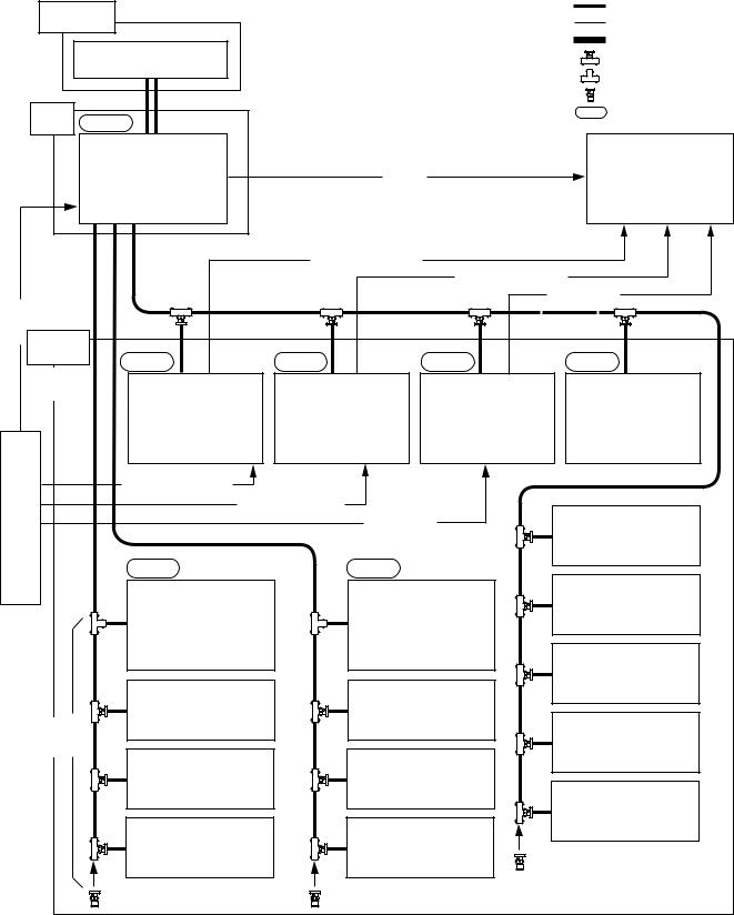
Example of S-BUS control system connection
Control |
|
: S-BUS |
|
|
|
||
Terminal |
|
: Signal Line |
|
Personal computer with a |
: RS-232C |
||
: T Bridge (A) |
|||
communication software or |
|||
Windows 3.1 installed |
*1 |
: T Bridge (B) |
|
|
|
||
|
|
: 75 ZTerminator *3 |
|
Primary |
|
: Matrix Level |
|
|
Station |
Level 1 |
REMOTE 3 |
|
|
|
||
|
|
|
Video Routing Switcher |
|
|
|
||
|
|
|
|
DVS-V64646B |
<Video> |
|
Destination VTR |
|
|
|
|
|
|
(M)*2 |
|
|
|
|
|
1 |
1 |
1 |
|
|
|
|
|
|
REMOTE |
REMOTE |
REMOTE |
|
<Audio Channel 1/2> |
|
|
|
|
|
|
<Audio Channel 3/4> |
||||
<Video> |
|
|
|
|
<Time Code> |
|||
|
|
|
|
|
||||
|
Secondary |
|
|
|
|
|
|
|
|
Station |
|
|
Level 2 |
Level 3 |
Level 4 |
Level 8 |
|
|
Maximum |
|
||||||
|
|
|
|
|
|
|
||
|
253 units |
|
|
|
|
|
|
|
|
|
|
|
|
Audio Routing Switcher |
Audio Routing Switcher |
Time Code |
Routing Switcher |
|
|
|
|
|
DVS-A3232 |
DVS-A3232 |
Routing Switcher |
|
|
|
|
|
|
(S)*2 |
|||
|
|
|
|
|
(S)*2 |
(S)*2 |
DVS-TC3232 |
|
|
|
|
|
|
|
|
(S)*2 |
|
|
|
|
|
<Audio Channel 1/2> |
|
|
|
|
Source |
|
|
|
<Audio channel 3/4> |
|
|
||
|
|
|
|
<Time Code> |
|
|||
VTR |
|
|
|
|
Display Unit |
|||
|
|
|
|
|
|
|||
|
|
|
|
|
|
|
|
BKS-R3280 |
|
|
|
|
|
Level 1 |
Level 1 |
|
|
|
|
|
|
|
Video Routing Switcher |
Video Routing Switcher |
Display Unit |
|
|
|
|
|
|
BKS-R3281 |
|||
|
|
|
|
|
DVS-V6464B |
|||
|
|
|
|
|
DVS-V3232B |
|
||
|
|
|
|
|
(S)*2 |
|
||
|
|
|
|
|
(S)*2 |
|
||
|
|
|
|
|
|
|
|
Remote Control Unit |
|
|
|
|
|
|
|
|
BKS-R1608 |
|
|
|
|
|
Remote Control Unit |
Remote Control Unit |
|
|
|
Maximum |
|
|
BKS-R3210 |
BKS-R1607 |
|
||
|
|
|
|
|
|
Remote Control Unit |
||
|
128 unit |
|
|
|
|
|
||
|
|
|
|
|
|
BKS-R3209 |
||
|
|
|
|
|
|
|
|
|
|
|
|
|
|
Remote Control Unit |
Remote Control Unit |
|
|
|
|
|
|
|
BKS-R3209 |
BKS-R3209 |
|
|
|
|
|
|
|
|
|
|
Remote Control Unit |
|
|
|
|
|
|
|
|
BKS-R3209 |
|
|
|
|
|
Remote Control Unit |
Remote Control Unit |
|
|
|
|
|
|
|
BKS-R3209 |
BKS-R3209 |
|
|
Either one of the REMOTE 1 connectors of the secondary station routing switchers can be used. *1: The function switch will be not working in the terminal mode of the Windows 95/NT.
*2: (M) and (S) mean the setting of M/S switch on the CPU board.
*3: Connect the 75 Zterminators to the T type bridge of the last device on a S-BUS data link and to the unused REMOTE 1 connector.
1-6 |
ROUTING SWITCHER SYSTEM (E) |

1-2. System Control
1-2-3. 9-pin remote control
The Sony digital routing switcher can be controlled from external control units connected to the REMOTE 2 (D-sub 9-pin) using RS-422A. For DVS-V3232B/V6464B, BKPF-R70 and HDS-V3232, the functions performed by 9-pin remote control, can especially be upgraded to a great extent. The following three kinds of 9-pin remote protocols can be used.
. Sony production switcher protocol
. Sony audio mixer protocol
. Sony cart protocol
n
The protocol that can be used depends on the models (refer to Section 1-2-1). BKPF-R70 is controlled by Sony cart protocol only.
The DVS-V3232B/V6464B, BKPF-R70 and HDS-V3232 can be switched between the “direct mode” in which they are controlled directly and to the “S-BUS conversion mode” in which cart protocol commands are converted to the S-BUS protocols.
In the direct mode, the switchers can be controlled individually. In the S-BUS conversion mode, up to 254 switchers on the S-BUS line (including the primary station) can be controlled.
For DVS-V3232B/V6464B/V1616/A3232 and HDS-V3232, the S-BUS and 9-pin remote control lines are connected to REMOTE 1 and 2 respectively and can be switched freely. Other switchers can be connected to either control line.
m
1.In the direct mode, the protect and secret functions set on the S-BUS protocol are not avail able.
2.In the S-BUS conversion mode, the “UA2” data specified by the cart protocol will be converted to the level values on S-BUS protocol.
In this mode, the protect and secret functions set on S-BUS protocol are available. (However, these functions cannot be set on the 9-pin remote control and the contents of the setting cannot be checked, either.)
3.The number of input/output signals that can be controlled on each protocol is as follows.
Protocol |
|
Control Area |
Cart Protocol*1 |
Cart |
1-16 |
|
Cart plus |
1-256 |
|
|
|
Audio mixer protocol |
|
1-128 |
|
|
|
Production Switcher Protocol |
1-127 |
|
|
|
|
4.When several DVS-V6464Bs are connected in a cascade and the input bus number is in creased, if controlled by the 9-pin remote, there is the case no signal is output.
To avoid such case, use the S-BUS conversion mode.
*1 : There are two kinds of cart protocol due to the control area.
Unless otherwise noted, “cart protocol” in this manual mean the cart plus protocol.
ROUTING SWITCHER SYSTEM (E) |
1-7 |
1-2. System Control
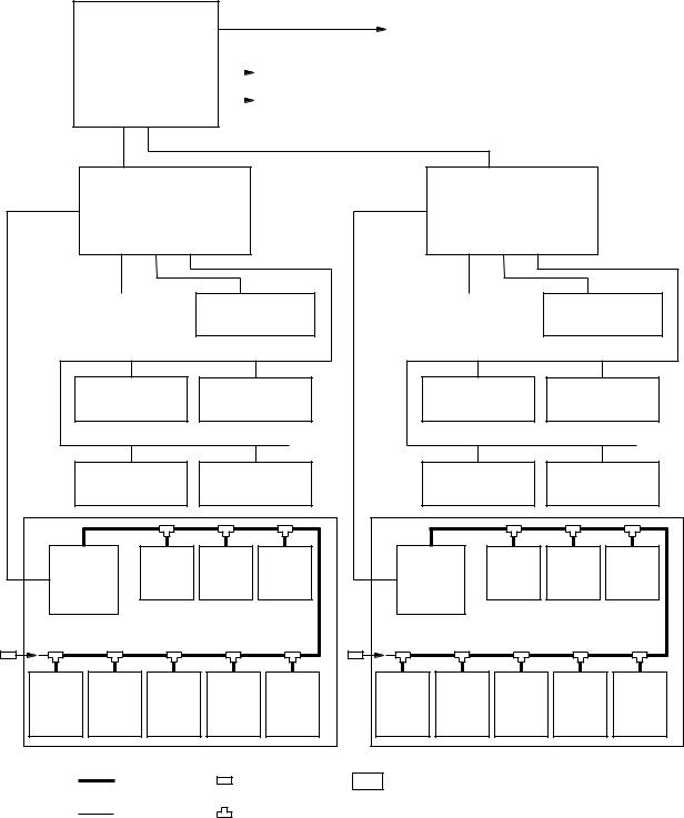
The following is an example of a 9-pin remote control connection.
System Console
Main Controller |
|
|
(Host CPU) |
|
Printer |
|
||
|
|
Local disk |
|
|
Sub Controller
(Interface Unit)
RS-422A
Status Display |
Status Display |
|
|
|
Remote Control |
Remote Control |
|||
|
Unit |
|
Unit |
|
|
2 |
|
|
|
|
|
REMOTE |
Remote Control |
Remote Control |
|||
Unit |
|
Unit |
|
||
|
|
|
|
||
|
REMOTE 1 |
|
|
|
|
|
|
DVS- |
DVS- |
DVS- |
|
DVS-V3232B |
V6464B |
V6464B |
V6464B |
||
(S) |
(S) |
(S) |
|||
(M) |
|||||
|
|
|
|||
|
S-BUS |
|
|
|
|
DVS-A3232 |
DVS-A3232 |
DVS-A3232 DVS-A3232 |
DVS- |
||
V6464B |
|||||
(S) |
(S) |
(S) |
(S) |
||
(S) |
|||||
|
|
|
|
||
|
: S-BUS |
: 75 Zterminator |
|||
|
: RS-422A |
: T bridge |
|||
Sub Controller
(Interface Unit)
RS-422A
Status Display |
Status Display |
|
|
|
Remote Control |
Remote Control |
|||
|
Unit |
|
Unit |
|
|
2 |
|
|
|
|
|
REMOTE |
Remote Control |
Remote Control |
|||
Unit |
|
Unit |
|
||
|
|
|
|
||
|
REMOTE 1 |
|
|
|
|
|
|
DVS- |
DVS- |
DVS- |
|
DVS-V3232B |
V6464B |
V6464B |
V6464B |
||
(S) |
(S) |
(S) |
|||
(M) |
|||||
|
|
|
|||
|
S-BUS |
|
|
|
|
DVS-A3232 |
DVS-A3232 |
DVS-A3232 |
DVS-A3232 |
DVS- |
|
V6464B |
|||||
(S) |
(S) |
(S) |
(S) |
||
(S) |
|||||
|
|
|
|
||
: Standard units making up Sony router system
(M) and (S) mean the setting of M/S switch on the CPU board.
1-8 |
ROUTING SWITCHER SYSTEM (E) |
1-2. System Control
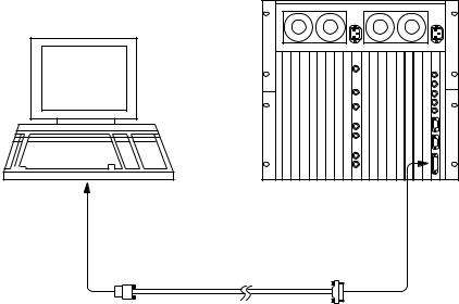
1-2-4. Connection of control terminal
Connect the control terminal to the REMOTE3 (D-sub 25-pin) connector of the primary station as shown below. The control terminal is used for setting of the router system and for displaying the information of errors, problems, system status, etc. during operation.
Use the personal computer installing the terminal software as the control terminal of the router system.
DVS-V6464B
Control terminal (IBM PC/AT compatibles)
To D-sub 9-pin |
To REMOTE 3 |
connector |
connector |
RS-232C cross cable (9-pin↔25-pin)
n
REMOTE 3 connector of BKPF-R70 and HDS-V3232 is D-sub 9-pin connector.
When BKPF-R70 or HDS-V3232 is set to the primary station, connect the control terminal to the unit by using the RS-232C cross cable.
The control terminal is not able to connect to the system which primary station is set to BKPF-300 series.
1-2-5. Control of monitor S-BUS system
DVS-V3232B/V6464B is able to monitor all the input and output signals when the optional monitor board BKDS-V3292B is installed, whose CPU is used exclusively for monitoring. It forms a monitor S- BUS data link via the REMOTE4 connector.
In this manual, the monitor control line is called “monitor S-BUS” to distinguish it from the control line of the main S-BUS using for changing crosspoints. The main S-BUS is called “standard S-BUS” or simply “S-BUS”. Excluding the system control, the monitor S-BUS has exactly the same protocol and communication format as that of the standard S-BUS.
The input monitor and output monitor can be either used separately or combined. They can be also connected in cascade. As the crosspoint control of the monitor is performed separately from the standard S-BUS control system, a primary station for the monitor S-BUS must be designated in addition to that set for the standard S-BUS.
The configuration of the monitor S-BUS is set with the control terminal connected to the primary station on the standard S-BUS.
ROUTING SWITCHER SYSTEM (E) |
1-9 |

1-2. System Control
The following shows one way of connecting the monitor S-BUS system.
|
|
<S-BUS> |
|
Secondary |
|
Primary |
|
Station (S) |
B type |
Station (M) |
A type |
DVS-V6464B |
|
DVS-V6464B |
|
(Max. 200 m)
(Inut signal)
Monitor
(Max. 200 m)
Secondary |
|
Station (S) |
D type |
DVS-V6464B |
|
Secondary |
|
Station (S) |
C type |
DVS-V6464B |
|
|
(Max. |
|
200 m) |
|
(Output/Input signal) |
|
(Max. 200 m) |
|
Monitor |
|
BKS-R3209 |
(M) (S) : M/S switch setting on the monitor Board.
: T Bridge (A)
: T Bridge (B)
: 75 ZTerminator
BKS-R3209
BKS-R3209
BKS-R3210
1-10 |
ROUTING SWITCHER SYSTEM (E) |
Section 2
Functions
2-1. Main Functions of Router System
1)The routing switcher is equipped with a system controller. It therefore does not require an additional controller for controlling the routing switchers.
2)By the cascade connection, up to 512 x512 crosspoints can be selected.
3)Up to 8 levels can be assigned.
4)Up to 254 units can be controlled in a system.
5)Each output signal can be protected so that they will not be switched by other control units. (Protect function)
6)Each input signal can be prohibited to be selected from all the control units. (Secret function) * 7) The inputs that can be selected for each output can be limited. (Crosspoint disable setting
function)
*8) Password function
*9) The either name of “Type +Number” or “Description” can be set for input/output connectors.
*10) A crosspoint matrix can be mapped on a virtual matrix. (Virtual mapping function)
*11) To each connector name, a different connector number can be assigned on each level.
(Free assignment function)
*12) Input and output signals can be monitored using the optional monitor board BKDS-V3292B. (Monitoring function)
*13) You can enable the system to automatically select the signal lines between two routing switchers. (Tie line function)
14)You can simultaneously switch several crosspoints. (Phantom function)
15)The control terminal connected to the primary station will display the system status informations and error messages. (Self-diagnosis function)
16)When DVS-7000 is connected to the destination of DVS-V3232B/V6464B, the source name of the routing switcher is indicated on the DVS-7000. (Route function)
17)BKS-R1607 and BKS-R3210 can restrict the crosspoint block of selection for each remote control unit.
*: DVS-V3232B/V6464B, BKPF-R70 and HDS-V3232 only (BKPF-R70 and HDS-V3232 has no monitor function described “12”).
DVS-V3232B/V6464B, BKPF-R70 and HDS-V3232 outstanding offers new functions as a primary station. To get the best out of the system, we recommend that DVS-V3232B/V6464B, BKPF-R70 or HDS-V3232 is used as a primary station.
BKPF-R70 switches the crosspoint at a highest speed in the four switchers by mounted RISC CPU.
The following outlines each function. (For details of how to set them, refer to the Section 5 “System Settings”.)
ROUTING SWITCHER SYSTEM (E) |
2-1 |
2-2. Built-in Controller
2-3. Matrix Sizes
2-4. Number of Levels
2-5. Number of Units
2-2. Built-in Controller
The Sony digital routing switcher incorporates a system controller and therefore does not require a separate external controller. When several routing switchers are connected to the S-BUS, the CPU of the switcher set as the primary station will control the whole system.
2-3. Matrix Sizes
By the cascade connection, input and output signals can be expanded to form a large-scale of router system.
Maximum matrix sizes depend on the kind of switchers.
. DVS-V6464B : 512 inputs x512 outputs
. DVS-A3232 : 256 inputs x256 outputs
. DVS-TC3232 : 256 inputs x256 outputs
. DVS-RS1616 : 128 inputs x128 outputs (at 16 mode) 256 inputs x256 outputs (at 32 mode)
. BKPF-300/350 : 112 inputs x2 outputs
. BKPF-301/351 : 32 inputs x2 outputs (BKPF-301), 1 output (BKPF-351)
n
DVS-V1616/V3232B, HDS-V3232 and BVS-V3232/A3232 are not able to connect by the cascade.
2-4. Number of Levels
The router system has the capability to control the different types of signal at the same time. This is enabled by the level setting.
The router system can handle the signals such as video, audio, timecode and the RS-422A remote control signal. These signals are switched by their exclusive switchers. The signals that perform switching are allocated in the different layers. These layers are called levels.
In the router system, the different numbers are given to the input and output signals of the respective layers that enable switching of various signals at the different levels simultaneously.
Example: Video can be set to level 1, audio to level 2, etc.
Up to eight levels can be set for one system.
The levels are set in the menu item [E : SET LEVEL TABLE].
2-5. Number of Units
Up to 128 remote control units and switchers can be connected to one S-BUS line. It is possible to control up to 254 units (including the primary station) in total of all lines.
2-2 |
ROUTING SWITCHER SYSTEM (E) |
2-6. Protect Function
2-7. Secret Function
2-8. Crosspoint Disable Setting Function (DVS-V3232B/V6464B, BKPF-R70 and HDS-V3232)
2-9. Password Function (DVS-V3232B/V6464B, BKPF-R70 and HDS-V3232)
2-6. Protect Function
Function which protects the crosspoint set so that it cannot be released using other remote control units. While the protect function is on, the destination of the crosspoint to be protected will be fixed. Once the protect is set, it will not be released by any command, except those from the control terminal and the control unit used to set it. The protect function can be set and released freely from the control terminal connected to the primary station.
The control terminal also has a password function which allows only certain users to operate the system. The protect function can be set in the menu item [C: SET DESTINATION NAME].
2-7. Secret Function
Function which “hides” certain sources from all control units to protect the crosspoint set so that it cannot be switched.
Unlike the protect function that limits the destinations, the secret function limits the sources to protect them from being selected by other control units.
The secret function can be set in the menu item [D: SET SOURCE NAME].
2-8. Crosspoint Disable Setting Function (DVS-V3232B/V6464B,
BKPF-R70 and HDS-V3232)
Function that limits the sources that can be selected for each destination. It can also be used to fix the area of crosspoints selected so that only certain sources can be selected for certain destinations. This function can be only used when a DVS-V3232B/V6464B, BKPF-R70 or HDS-V3232 is assigned as the primary station.
This function can be set in the menu item [M: SET INHIBIT TABLE].
2-9. Password Function
(DVS-V3232B/V6464B, BKPF-R70 and HDS-V3232)
The control terminal can set all configuration items of the routing switcher system. It therefore has a password function which allows only certain users to operate it. The password can be set in the menu item [P: CHANGE PASSWORD].
ROUTING SWITCHER SYSTEM (E) |
2-3 |
2-10. Setting the Input/Output Name (DVS-V3232B/V6464B, BKPF-R70 and HDS-V3232)
2-10. Setting the Input/Output Name
(DVS-V3232B/V6464B, BKPF-R70 and HDS-V3232)
The following names can be used for the input/output connectors of the routing switcher.
1.“Type+Number” name
2.”Description“ name
There are altogether three kinds of numbers that can be set as input/output numbers. These are “physical number”, “connector number”, and “virtual number”.
The physical number and connector number are the number of connectors attached to the switcher. For a DVS-V6464B, it is 1 to 64. For a DVS-V3232B, it is 1 to 32. The difference between the physical number and connector number is that the connector number is used for each switcher frame, while the physical number is used for one router system that is either single frame or multiple cascading frames. Usually the physical number is used for the S-BUS control system, while the connector number is used for the RS-422A (9-pin remote) control system.
The virtual number is the numbers assigned when switchers are mapped on a virtual matrix with 512 inputs and 512 outputs. The numbers will not duplicate even if several switchers are mapped on the virtual matrix. Unless otherwise noted, the input/output number in this manual means the virtual number.
|
|
|
INPUT |
|
|
|
Virtual number |
152 |
88 |
25 |
18 |
9 |
1 |
|
|
|
|
|
|
1 |
|
|
|
|
|
|
DVS-V1616 |
|
|
|
|
|
|
(LEVEL-1) |
|
|
|
|
|
|
5 |
|
|
|
|
|
DVS-V1616 |
|
|
|
|
|
|
(LEVEL-8) |
|
|
|
|
|
|
|
10 |
Physical number |
128 |
65 64 |
1 |
|
|
OUTPUT |
|
|
|
||||
(Connector number) |
(64) |
(1) (64) |
(1) |
1 |
|
12 |
|
|
|||||
|
DVS-V6464B |
|
DVS-V6464B |
|
|
|
|
|
|
(64) |
64 |
|
75 |
|
|
|
|
|
|
|
|
(Connector number) |
Physical number |
|
|||
|
|
|
|
|
|
Virtual number |
Virtual Matrix
2-4 |
ROUTING SWITCHER SYSTEM (E) |
2-10. Setting the Input/Output Name (DVS-V3232B/V6464B, BKPF-R70 and HDS-V3232)
The name “Type + Num” consists of four alphabets and three numbers. It is assigned to the virtual number. Sixteen kinds of letters can be set for the “Type” part. Number 1 to 999 can be used for the “Num” part.
Examples: CAM 234, VTR 145
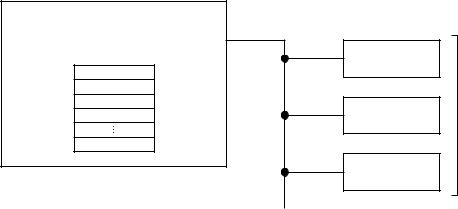
The name “Description” consists of any 16 characters and is assigned to the virtual number, e.g. “Tokyo” and “Market”. Up to 1024 kinds of names can be registered. The 160 kinds of them are transmitted to the remote control unit in order to set buttons and for displaying. The 160 names can be registered as one group. Data of 8 groups can be registered at the primary station. The data of remote control unit can be replaced by a group and the different data groups can be used for each remote control unit
Primary station (DVS-V3232B/V6464B, HDS-V3232)
8 groups
No. 1
No. 2
No. 3
No. 4
No. 8
1group : 160 names
Remote control unit
No. 2 group
No. 2 group
1 group for each unit
No. 4 group
Description Name
The name “Description” can be selected the “DESCRIP. NAME” in the menu item [J: NAME STYLE] when a DVS-V3232B/V6464B, BKPF-R70 or HDS-V3232 is used as the primary station.
After the selection, set the description name in the menu item [C : SET DESTINATION NAME] or [D : SET SOURCE NAME].
ROUTING SWITCHER SYSTEM (E) |
2-5 |
2-11. Virtual Mapping Function (DVS-V3232B/V6464B, BKPF-R70 and HDS-V3232)
2-11. Virtual Mapping Function
(DVS-V3232B/V6464B, BKPF-R70 and HDS-V3232)
Several routing switchers can be mapped on a virtual matrix with 512 inputs and 512 outputs in router system. The matrix of one switcher can be also divided into several virtual levels and mapped.
For example, a switcher handling the 4:2:2 video signal and a switcher handling the 4 fsc video signal can be mapped on the same level. By connecting them using a 4:2:2/4 fsc converter, the tie line control can be performed (refer to Section 2-14).
DVS-A3232 has two modes such as 2-channel mode and 4-channel mode. Normally, either one will be selected. However it is possible to use the overlapping area as the 4-channel mode by dividing the matrix into two in the 2-channel mode and assigning them to the different virtual levels.
In the figure below, the 12 x12 area where the level 2 and level 3 is overlapping is set to the 4 -channel mode while the other is set to the 2-channel mode in the 20 x20 area.
|
DVS-A3232 |
|
|
|
|
12 |
1 |
|
(2-channel mode) |
|
Mapping to LEVEL-2 (1 to 20) |
LEVEL-3 |
|
1 |
|
32 |
20 |
12 |
1 |
|
|
||
|
(AUDIO-2) |
|
|
||||
|
|
|
1 |
|
|
|
|
|
|
|
|
20 |
12 |
1 |
12 |
|
|
|
|
|
|
1 |
|
|
|
|
|
LEVEL-2 |
|
|
|
|
|
|
12 |
|
|
|
|
|
|
|
(AUDIO-1) |
|
|
|
|
|
|
|
|
|
|
12 |
|
|
|
|
20 |
|
|
|
|
|
|
|
|
|
|
20 |
|
|
|
|
32 |
|
|
|
|
Mapping to LEVEL-3 (1 to 12)

 : 2-channel mode

 : 4-channel mode
It is called “Virtual mapping” that you assign crosspoints using the virtual matrices and virtual levels in this way.
This virtual mapping function can be set in the menu item [L: SET PHYSICAL ASSIGNMENT] when a DVS-V3232B/V6464B, BKPF-R70 or HDS-V3232 is used as the primary station.
n
When the matrix of a DVS-V3232B/V6464B is divided into two or more matrices on multiple virtual levels, the monitor function for input/output signals may not work correctly.
2-6 |
ROUTING SWITCHER SYSTEM (E) |

2-12. Free Assignment Function (DVS-V3232B/V6464B, BKPF-R70 and HDS-V3232)
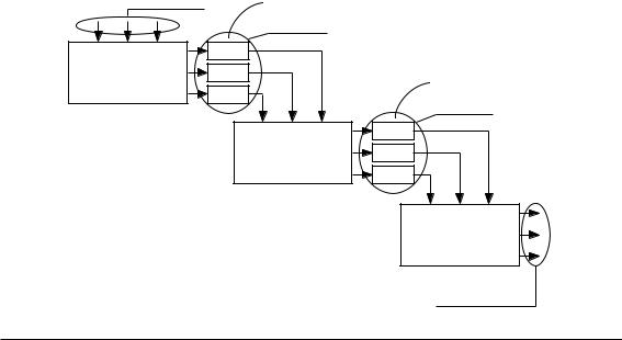
2-12. Free Assignment Function
(DVS-V3232B/V6464B, BKPF-R70 and HDS-V3232)
While the same input/output number can be assigned, through levels 1 to 8, for each input/output name, different physical number can also be assigned on each level for an input/output name.
The following figure shows the case that DVS-V6464B is used for level 1 and DVS-A3232 for levels 2 and 3. To source IN002, physical number 5 can be assigned on level 1, physical number 2 on level 2, and physical number 18 on level 3.
Similarly, to destination OUT004, physical number 32 can be assigned on level 1, physical number 32 on level 2, and physical number 4 on level 3.
|
|
|
18 |
|
|
LEVEL-3 |
|
|
(AUDIO-2) |
2 |
|
|
LEVEL-2 |
|
4 |
|
|
|
|
32 |
(AUDIO-1) |
5 |
|
|
LEVEL-1 |
|
32 |
|
(VIDEO) |
|
|
|
IN002 |
|
32 |
|
OUT004 |
|
|
This free assignment function can be set in the menu item [L: SET PHYSICAL ASSIGNMENT] when a DVS-V3232B/V6464B, BKPF-R70 or HDS-V3232 is used as the primary station.
ROUTING SWITCHER SYSTEM (E) |
2-7 |
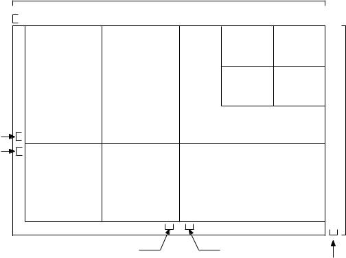
2-13. Monitor Function (BKDS-V3292B only)
2-13. Monitor Function (BKDS-V3292B only)
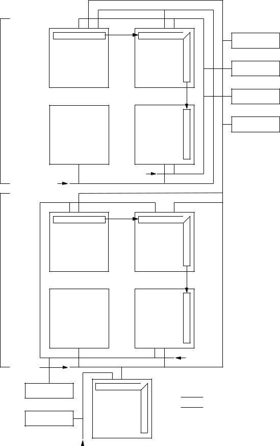
If a DVS-V3232B/V6464B is equipped with the optional BKDS-V3292B, any input/output signal can be monitored. The input and output signals can be observed on different monitors or on the same monitor by switching channels.
By connecting the monitor signals of several switchers in cascade form, all input and output signals can be observed on one monitor.
The crosspoints of monitor signals are controlled by the monitor S-BUS (the control line similar to the standard S-BUS although it controls only the monitor system).
The primary station on the monitor S-BUS is independent from the primary station on the standard S-BUS. Therefore, several monitor S-BUS can be set to one system.
For example, switchers (P-2) and (P-3) in the figure on next page serve as the primary station on the monitor S-BUS independently, while the switcher (P-1) serves as the primary station on the standard S- BUS and monitor S-BUS.
|
Input |
|
Input |
|||
(Input) 128 |
|
65 |
64 |
|
|
1 |
|
|
|||||
1
 Input Monitor (Separate connection)
DVS-V6464B |
|
|
|
DVS-V6464B |
|
|
|
|
|
Output |
||
|
|
|
|
|
|
|
||||||
(B Type) |
|
|
|
(A Type) |
|
|
|
|
|
|
||
|
|
|
|
|
|
|
|
|
64 |
|
||
|
|
|
|
|
|
|
|
|
||||
|
|
|
|
|
|
|
|
|
|
65 |
|
|
|
|
|
|
|
|
|
|
|
|
|
||
|
|
|
|
|
|
|
|
|
|
|
||
DVS-V6464B |
|
|
|
DVS-V6464B |
|
|
|
|
|
Output |
||
|
|
|
|
|
|
|
||||||
|
|
|
|
|
|
|
|
|
||||
(D Type) |
|
|
|
(C Type ) |
|
|
|
|
|
|
||
|
|
|
|
|
|
|
|
|
|
128 |
|
|
|
|
|
|
|
|
|
|
|
|
|
||
|
|
|
|
|
|
|
|
|
|
(Output) |
||
|
|
|
|
|
|
|
||||||
|
|
|
|
|
Output Monitor (Separate connection) |
|||||||
|
|
|
|
|
|
|
|
or |
||||
|
|
|
|
|
Input + Output Monitor (Combined connection) |
|||||||
m
1.For DVS-V3232B/V6464B routing system, the primary station on the standard S-BUS and monitor S- BUS should be the same.
However, for the monitor S-BUS which does not include the primary station on the standard S-BUS, any switcher can be assigned the primary station.
2.BKS-R1601/R3203/R3206 cannot be used as a secondary station on the monitor S-BUS.
2-8 |
ROUTING SWITCHER SYSTEM (E) |
|
|
2-13. Monitor Function (BKDS-V3292B only) |
|
|
BKS-R3204 |
DVS-V6464B |
DVS-V6464B |
|
(P-1) |
|
BKS-R3204 |
|
|
|
ConnectionCascade |
|
BKS-R3204 |
|
|
|
|
|
BKS-R3206 |
DVS-V6464B |
DVS-V6464B |
|
|
75 Z |
|
75 Z |
Terminate |
|
|
|
|
Terminate |
|
|
DVS-V6464B |
DVS-V6464B |
|
ConnectionCascade |
(P-2) |
|
|
|
|
DVS-V6464B |
DVS-V6464B |
|
|
|
75 Z |
75 Z |
|
Terminate |
|
|
|
Terminate |
|
|
BKS-R3204 |
|
|
|
|
: Standard S-BUS Line |
|
DVS-V6464B |
: Monitor S-BUS Line |
|
|
BKS-R3204
(P-3)
75 ZTerminate 
ROUTING SWITCHER SYSTEM (E) |
2-9 |
2-14. Tie Line Management (DVS-V3232B/V6464B, BKPF-R70 and HDS-V3232)
2-14. Tie Line Management
(DVS-V3232B/V6464B, BKPF-R70 and HDS-V3232)
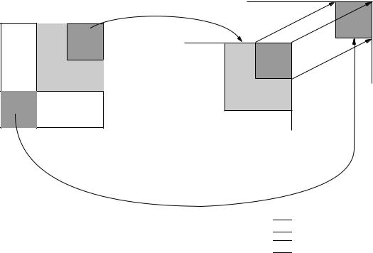
If the primary station is a DVS-V3232B/V6464B, BKPF-R70 or HDS-V3232, by previously setting four signal paths between routing switchers, unused signal paths can be selected automatically and protected when input and output names are selected. This function is called tie line management. It is effective to share the minimum number of converters (4:2:2:/4 fsc, 4 fsc/4:2:2, etc.).
For example, if both a 4:2:2 video switcher and a 4 fsc video switcher have 32 sources and destinations, the converters can be shared using the tie line function and all sources and destinations can be handled with the minimum number of converters.
Source group |
Converter |
Net group
Converter
Net group
Routing Switcher
(4 : 2 : 2)
Routing Switcher
(4 fsc)
Destination group
Setting Procedure of the Tie Line
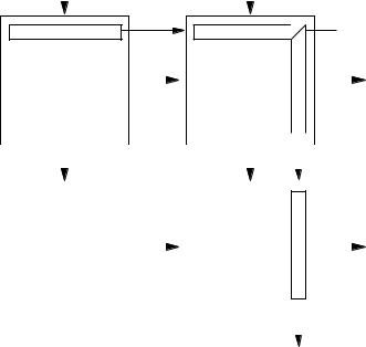
1.Set four input/output for each source/destination*1 group.
2.Set the four cables connecting the switchers for each net groups such as “OUT ***_IN ***”.
3.Set the path from the source group to the destination (the path consists of the selected group names)
*1 : Source means the input signal. Destination means the output signal.
2-10 |
ROUTING SWITCHER SYSTEM (E) |
Loading...