


READ THE INSTRUCTIONS MANUAL CAREFULLY
Failure to read the manual, misunderstandings or incorrect interpretation of the instructions herein may result in damage to the appliance. Moreover, such action may also become a source of danger for the user and considerably lower the performances of the machine.
The manufacturer declines all liability for use of the machine differing from that described in this manual.
The machine must only be installed, serviced and repaired by authorized personnel.
The warranty could become void if the machine is used in a way that Fails to Conform to the instructions given by SMEG.
The text and illustrations in this manual are for informative purposes only. The contents and appliance described herein may be liable to modification without prior notice. In no case may SMEG be held liable for any direct or indirect damages deriving from or in relation to use of this manual.
19 390 2191 01 |
02/03/2011 |
|
|
Rev. |
Date |
|
|
Rev. 01 |
Man. WD1050 |
Pag. 1 - 40 |
|
|
|

Information or Assistance for products from the SMEG Instruments Division
If so, please contact us from 8 a.m. until 6 p.m. at the following numbers and addresses:
www.smeg-instrumens.com instruments@smeg.it
Fax +39 0522 821 592
Tel +39 0522 8211
Our Sales Office staff will give you all the info you require about prices and offers. You can also view our entire production range in our web site along with any innovations.
Our Technical Assistance Office staff can tell you how to operate your appliance in the correct way or put you in contact with your nearest Authorized Assistance Centre if necessary.
International customers, please contact your local SMEG distributor.
Rev. 01 |
Man. WD1050 |
Pag. 2 - 40 |
|
|
|

TABLE OF CONTENTS |
|
|
1. |
INTRODUCTION ................................................................................................ |
5 |
2. |
SYMBOLS LEGEND .......................................................................................... |
6 |
3. |
GENERAL RECOMMENDATIONS ..................................................................... |
6 |
4. |
GENERAL SPECIFICATIONS............................................................................ |
8 |
4.1. TECHNICAL FEATURES............................................................................................. |
8 |
|
4.2. LIFTING AND HANDLING ............................................................................................ |
9 |
|
4.3. DOOR LOCKING SYSTEM .......................................................................................... |
9 |
|
4.4. MANUAL DOOR UNLOCKING ................................................................................... |
10 |
|
5. |
INSTALLATION ............................................................................................... |
11 |
5.1. POSITIONING ........................................................................................................... |
11 |
|
5.2. LEVELLING............................................................................................................... |
11 |
|
5.3. CONNECTION TO WATER MAINS ............................................................................ |
12 |
|
5.4. WATER SUPPLY ....................................................................................................... |
13 |
|
5.5. NON PRESSURIZED DEMINERALIZED WATER CONNECTION ................................ |
14 |
|
5.6. WATER DRAIN CONNECTION .................................................................................. |
15 |
|
5.7. ELECTRICAL CONNECTION..................................................................................... |
16 |
|
6. |
DESCRIPTION OF CONTROLS ....................................................................... |
17 |
6.1. SETUP DESCRIPTION .............................................................................................. |
18 |
|
6.2. WASHING PROGRAMME SETTINGS ........................................................................ |
20 |
|
6.3. THERMAL DISINFECTION IN ACCORDANCE WITH THE PARAMETER "A0"............. |
20 |
|
6.4. PROGRAMMES DESCRIPTION ................................................................................ |
22 |
|
6.5. MACHINE RUNNING ................................................................................................. |
23 |
|
6.6. RESIN WASHING PHASE ......................................................................................... |
24 |
|
6.7. RESIN REGENERATION PHASE............................................................................... |
24 |
|
6.8. PROGRAMME TERMINATION .................................................................................. |
24 |
|
6.9. IN PROGRESS PROGRAMME INTERRUPTION ........................................................ |
24 |
|
6.10. RESET PROCEDURE.............................................................................................. |
24 |
|
6.11. DATE AND TIME SETUP ......................................................................................... |
25 |
|
6.12. DEMI WATER SETTING .......................................................................................... |
26 |
|
6.13. PRINTER ................................................................................................................ |
26 |
|
6.14. PRINTER LANGUAGE............................................................................................. |
27 |
|
7. |
OPERATING INSTRUCTIONS ......................................................................... |
28 |
7.1. USE OF THE WATER SOFTENER ............................................................................. |
28 |
|
7.2. USE OF THE DETERGENT AND NEUTRALIZING AGENT ......................................... |
29 |
|
7.3. DETERGENT AND NEUTRALIZING AGENT RECOMMENDED BY SMEG .................. |
29 |
|
8. |
ALARMS .......................................................................................................... |
31 |
9. |
CLEANING AND MAINTENANCE.................................................................... |
34 |
9.1. RECOMMENDATIONS AND GENERAL ADVICE........................................................ |
34 |
|
9.2. IF THE INSTRUMENT WASHER IS NOT USED FOR A LONG PERIOD OF TIME ........ |
37 |
|
9.3. REUSE OF THE INSTRUMENT WASHER AFTER A LONG PERIOD OF INACTIVITY . 37 |
||
9.4. TROUBLESHOOTING ............................................................................................... |
37 |
|
Rev. 01 |
Man. WD1050 |
Pag. 3 - 40 |
|
|
|

10. |
ROUTINE CHECKS ......................................................................................... |
39 |
10.1. DAYLY .................................................................................................................... |
39 |
|
10.2. WEEKLY ................................................................................................................. |
39 |
|
10.3. HALF YEARLY ........................................................................................................ |
39 |
|
10.4. YEARLY .................................................................................................................. |
39 |
|
11. |
WD1050 DIMENSIONS .................................................................................... |
40 |
Rev. 01 |
Man. WD1050 |
Pag. 4 - 40 |
|
|
|

1. INTRODUCTION
This manual is an integral part of the machine.
It must be kept in a good condition and ready to hand for the entire life cycle of the machine. We advise you to carefully read this manual and all the instructions it contains before using the appliance.
This appliance conforms to the EEC Directive 2007/47 currently in force.
The appliance has been made in order to:
-wash Surgical and Dental Instruments with Thermal Disinfection1;
-the appliance cannot be used to sterilize instruments or any other device.
All other uses are considered improper.
The manufacturer declines all liability for uses differing from those indicated.
The manufacturer declines all responsibility for any possible damage caused by the washing of instruments whose manufacturers have not authorized to be automatically decontaminated.
The instrument washer complies with all the requisites established by the current safety standards governing electrical equipment. Technical inspections must only be made by specialized and authorized personnel.
BESIDES VOIDING THE WARRANTY, REPAIRS MADE BY UNAUTHORIZED PERSONNEL MAY REPRESENT A DANGER HAZARD FOR THE USER.
1 Treatment in the Instrument Washer can never be a substitute for sterilizing. Disinfection in the instrument washer is carried out to reduce the risks sustained by the persons who handle surgical instruments when preparing them for sterilization and to guarantee a better successive sterilization process.
Rev. 01 |
Man. WD1050 |
Pag. 5 - 40 |
|
|
|

2. SYMBOLS LEGEND
Carefully read the paragraph.
Attention, Danger, see the manual.
Attention, hot surface.
~Alternating current.
CE mark, notified body: IMQ.
At the end of life the product should be sent to disposal facilities for the recovery and recycling.
3.GENERAL RECOMMENDATIONS
Never use solvents such as alcohol or turpentine in the appliance as they could cause an explosion. Never put instruments dirtied with ash, wax or paint in the appliance.
Do not rest or sit on the open door of the instrument washer as this could cause the appliance to overturn and thus represent a danger hazard for persons. The maximum weight loaded onto the open door, including the weight of the instrument trolley, must never exceed 30kg.
Rev. 01 |
Man. WD1050 |
Pag. 6 - 40 |
|
|
|
Never ever touch the heating element immediately after a washing cycle has terminated.
The heating element could become slightly darkened during use of the instrument washer, even to a localized extent. This should be considered normal as it depends on the operating mode and does not impair the way the appliance works.
At the end of its working life, the appliance must be rendered unusable. Cut off the power flex after having removed the plug from the power socket. The appliance must then be consigned to an authorized disposal center.
If the appliance operates in a faulty way, unplug it from the electricity main, shut off the water cock and contact your nearest authorized Assistance Center.
Only open the door after the washing cycle has terminated.
If you open the door while a programme is in progress, hot water, steam and other liquids will spill out and may injure the user. Only authorized and well-informed personnel are allowed to use the machine.
Rev. 01 |
Man. WD1050 |
Pag. 7 - 40 |
|
|
|

4. GENERAL SPECIFICATIONS
4.1. TECHNICAL FEATURES
|
|
|
|
|
|
|
|
|
|
|
|
|
|
|
|
|
|
|
|
|
|
|
|
|
|
|
|
MODELS |
|
WD1050 |
|
WD1050-3 |
|
WD1050-1 |
||||
|
|
|
|
|
|
|
|
|
|
|
|
|
|
|
|
|
|
|
|
|
|
|
|
||
|
|
|
|
ELECTRIC POWER SUPPLY |
|
|
|
|
||||
|
|
|
|
|
|
|
|
|
|
|
|
|
|
VERSION |
|
Triphase 400V |
|
Trifase 230V |
|
Monophase 230V |
|||||
|
|
|
|
|
|
|
|
|
|
|
|
|
|
|
|
|
|
|
|
|
|
|
|
|
|
|
TYPE OF VOLTAGE |
|
400V 3/N/E |
|
230V 3/PE |
|
230V 1/N/PE |
|||||
|
[tolerated variation 10%] |
|
|
|
||||||||
|
|
|
|
|
|
|
|
|
|
|
||
|
|
|
|
|
|
|
|
|
|
|
|
|
|
|
|
|
|
|
|
|
|
|
|
||
|
FREQUENCY [HZ] |
|
|
|
50 |
|
|
|
|
|||
|
|
|
|
|
|
|
|
|
|
|
|
|
|
POWER RATING [KW] |
|
7 kW |
|
7 kW |
|
|
2,8 kW |
||||
|
|
|
|
|
|
|
|
|
|
|
|
|
|
|
|
|
|
|
|
|
|
|
|
|
|
|
AUTOMATIC SWITCH ON |
|
In 16 A 3P+N 400V |
In 20A 3P 400V Icn |
|
In 16 A P+N 230V |
||||||
|
MACHINE |
|
Icn 4500 A |
|
6000 A |
|
|
Icn 4500 A |
||||
|
|
|
|
|
|
|
|
|
|
|
||
|
|
|
|
|
|
|
|
|
|
|
|
|
|
|
|
|
|
|
|
|
|
|
|||
|
|
|
|
WATER SUPPLY |
|
|
|
|
||||
|
|
|
|
|
|
|
|
|
|
|
|
|
|
TYPE OF WATER |
|
COLD WATER |
|
|
|
DEMINERALISED WATER |
|||||
|
|
|
|
|
|
|
|
|
|
|
|
|
|
|
|
|
|
|
|
|
|
|
|
|
|
|
|
|
|
|
|
|
|
|
|
|||
|
PRESSURE [BAR] |
|
2 – 5 |
|
|
|
|
|
2 – 5 |
|||
|
|
|
|
|
|
|
|
|
|
|
|
|
|
|
|
|
|
|
|
|
|
|
|
|
|
|
|
|
|
|
|
|
|
|
|
|
|
|
|
TYPE OF CONNECTION |
3/4" |
|
|
|
|
|
|
3/4" |
|
||
|
|
|
|
|
|
|
|
|
|
|
|
|
|
|
|
|
|
|
|
|
|
|
|
|
|
|
MAX HARDNESS [°F] / |
|
42°F |
|
|
|
|
|
Max 20μS |
|||
|
CONDUCTIVITY[ S/CM] |
|
|
|
|
|
|
|||||
|
|
|
|
|
|
|
|
|
|
|
||
|
|
|
|
|
|
|
|
|
|
|
|
|
|
|
|
|
|
|
|
|
|
|
|
||
|
IRON [PPM] FE MAX |
|
|
|
< 0.5 |
|
|
|
|
|||
|
|
|
|
|
|
|
|
|
|
|
|
|
|
|
|
|
|
|
|
|
|
|
|
|
|
|
DRAIN |
|
FROM FLOOR LEVEL (on which machine is placed) |
|||||||||
|
|
|
|
|
|
|
|
|
|
|
|
|
|
|
|
|
|
|
|
|
|
|
|
|
|
|
HEIGHT [MM] |
|
|
Min 650 - Max 800 |
|
|
||||||
|
|
|
|
|
|
|
|
|
|
|
|
|
|
|
|
|
|
|
|
|
|
|
|
|
|
|
DIAMETER [MM] |
|
|
|
Min 40 |
|
|
|
|
|||
|
|
|
|
|
|
|
|
|
|
|
|
|
|
|
|
|
|
|
|
|
|
|
|
|
|
|
|
|
|
DIMENSIONS |
|
|
|
|
|
|
|
|
|
|
|
|
|
|
|
|
|
|
|
|
|
|
HEIGHT |
|
|
|
850 |
|
|
|
|
|||
|
|
|
|
|
|
|
|
|
|
|
|
|
|
|
|
|
|
|
|
|
|
|
|
|
|
|
DEPTH |
|
|
|
670 |
|
|
|
|
|||
|
|
|
|
|
|
|
|
|
|
|
|
|
|
|
|
|
|
|
|
|
|
|
|
|
|
|
WIDTH |
|
|
|
600 |
|
|
|
|
|||
|
|
|
|
|
|
|
|
|
|
|
|
|
|
|
|
|
|
|
|
|
|
|
|
|
|
|
NET WEIGHT [KG] |
|
|
|
65 |
|
|
|
|
|||
|
|
|
|
|
|
|||||||
|
Material used |
|
Washing chamber AISI 316L |
|
External cladding AISI 304 |
|||||||
|
|
|
|
|
|
|
|
|
|
|
|
|
|
|
|
|
|
|
|
|
|||||
|
|
|
ENVIRONMENTAL CONDITIONS |
|
|
|
|
|||||
|
|
|
|
|
|
|
|
|
|
|
|
|
|
USE |
|
|
|
Indoor |
|
|
|
|
|||
|
|
|
|
|
|
|
|
|||||
|
|
|
|
|
|
|
|
|
|
|
|
|
|
ALTITUDE |
|
|
|
Up to 1000m |
|
|
|||||
|
|
|
|
|
|
|
|
|||||
|
|
|
|
|
|
|
|
|
|
|
|
|
|
TEMPERATURE |
|
|
|
From 5°C to 40°C |
|
|
|||||
|
|
|
|
|
||||||||
|
|
|
|
|
|
|
|
|
|
|
|
|
|
RELATIVE HUMIDITY |
|
80% for temperatures up to 31°C with linear diminution down to 50% |
|||||||||
|
|
at the temperature of 40°C |
|
|
||||||||
|
|
|
|
|
|
|||||||
|
|
|
|
|
|
|
|
|
|
|
||
|
|
|
|
|
|
|
|
|
|
|
|
|
|
INSTALLATION CATEGORY |
|
|
|
|
II |
|
|
|
|
||
|
|
|
|
|||||||||
|
|
|
|
|
|
|
|
|
|
|
|
|
|
CLASS TO WHICH |
|
IIb (in compliance with the classification criteria established by DIRECTIVE |
|||||||||
|
APPLIANCE BELONGS |
|
|
|
2007/47) |
|
|
|
|
|||
|
|
|
|
|
|
|
|
|
|
|
||
|
|
|
|
|
|
|
|
|
|
|
|
|
|
|
|
|
|
|
|
|
|
|
|
|
|
|
POLLUTION DEGREE |
|
|
|
2 |
|
|
|
|
|
||
|
|
|
|
|
|
|
|
|
|
|
|
|
|
|
|
|
|
|
|
|
|
|
|
|
|
|
|
|
|
|
|
|
|
|
|
|
|
|
|
|
Rev. 01 |
|
Man. WD1050 |
|
|
|
Pag. 8 - 40 |
|
|||
|
|
|
|
|
|
|
|
|
|
|
|
|
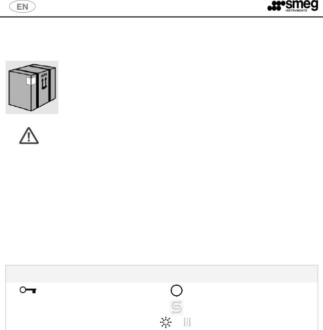
4.2. LIFTING AND HANDLING
Before it leaves the factory, the base of the machine is fixed to a pallet which is then used to lift and transport the machine itself.
The machine must be handled with a fork-lift truck or transpallet.
Do not use appliances damaged by transport! Consult your dealer if in doubt.
The appliance must only be installed and connected by personnel authorized by the manufacturer.
4.3. DOOR LOCKING SYSTEM
After unpacking, pay attention to the following:
the machine is equipped with an automatic door locking/unlocking system .
The door is locked. Don‟t force the door, but follow the procedure below.
Connect the machine to the mains supply;
push the ON/OFF button (in order to switch on the machine)
push (and hold) the button with the symbol of the key and after some seconds the door opens
SIGNS ON THE FRONT OF THE MACHINE
|
|
|
|
Door unlocking |
|
|
|
|
|
ON / OFF |
||
|
|
|
|
|
|
|
|
|
||||
|
|
|
|
|
|
|
|
|
||||
|
|
|
|
|
|
|
|
|
|
|
|
|
|
°C |
|
|
Temperature |
|
|
|
|
|
|
Salt Lack |
|
|
|
|
|
|
|
|
|
|
|
|||
|
|
|
|
|
|
|
|
|
|
|
|
|
|
► ll |
|
START / PAUSE |
|
or |
|
|
Heating element on |
||||
|
|
|
|
|
|
|
|
|
|
|
||
Rev. 01 |
Man. WD1050 |
Pag. 9 - 40 |
|
|
|

fig. 1 – WD1050 front.
In order to open the door without connecting the machine to the mains, the manual unlocking procedure must be executed. Please, see the following paragraph for further details.
4.4. MANUAL DOOR UNLOCKING
In case of emergency or in case of a power failure the door may be manually opened inserting a small screwdriver under the handle, as shown on the image.
fig. 2 – WD1050 front. To unlock the door manually: 1 - push the handle opening to access the opening mechanism, 2 - Force, pushing it from bottom to top, with a small screwdriver the opening mechanism.
Insert the screwdriver carefully into the yellow marked hole till the characteristic
“CLACK” is heard.
Rev. 01 |
Man. WD1050 |
Pag. 10 - 40 |
|
|
|
5. INSTALLATION
IMPORTANT: The machine must be positioned against the wall (minimum distance 10 cm) and must be installed by a technician authorized by the manufacturer.
The technician who installs the machine is responsible for the appliance operating correctly after it has been installed. He is also obliged to provide the user with all the information required to use the machine in the correct way.
All adjustments, servicing and so forth, must be carried out with the appliance disconnected from the electricity main.
The scratch-proof film must be removed from the external steel surfaces when the appliance is installed.
IT IS STRICTLY FORBIDDEN FOR UNAUTHORIZED PERSONS TO USE THE MACHINE.
5.1. POSITIONING
The side panels of the machine must adhere to the adjacent furniture and care must be taken to leave space at the rear: it is therefore advisable for the wall at the back to be made of brickwork or some other impermeable material.
The machine has pipes to supply and drain off the water. These can be positioned towards the right or left, depending on the installation requirements.
The machine can also be installed under a work top: this operation must be carried out by specialized personnel.
5.2. LEVELLING
Once the machine has been set in position, it must be levelled until horizontal (2 degrees tolerance allowed) by either screwing in the feet or unscrewing them.
Correct levelling will ensure that the machine operates in the right way.
Rev. 01 |
Man. WD1050 |
Pag. 11 - 40 |
|
|
|
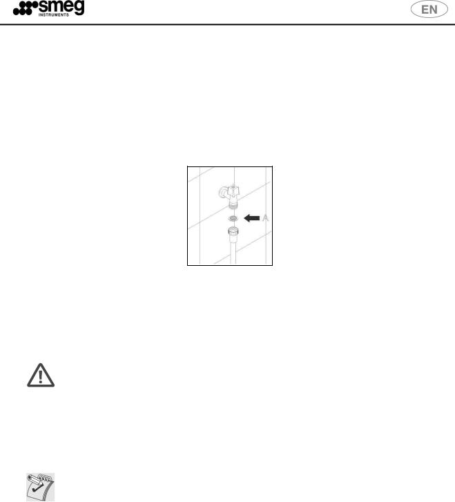
5.3. CONNECTION TO WATER MAINS
Prevent the risk of clogging or damage to the appliance: if the water pipe is new or has remained unused for a long period of time, make sure that the water is limpid and free from impurities before connecting the machine to the water main.
The pipe is pre-engineered for connection to a cock with 3/4‟‟ gas threaded union on both ends.
Insert the supplied filters "A" before connecting the other ends of the pipes to their respective cocks.
It is advisable to allow the water to run in order to drain off any rusty deposits or sludge if connections are made with new pipes.
In case of blood-stained instruments make sure that the machine is not supplied with water at temperature higher than 40°C.
WARNING
Make sure that the inlet pressure of the mains water is within the operating limits: min. 2 bar - max 5 bar.
The water shutoff valves must be accessible
Always shut off the water supply cocks when the machine is not being used
CAUTION
Chemical characteristics of mains water that are not compatible with a good washing process.
If the water contains more than 0.5 ppm of iron Fe2+/Fe3+ and/or the hardness of the water is more than 42°F (French degrees), it must be pre-treated by installing a deferrization and/or softening system upstream.
Rev. 01 |
Man. WD1050 |
Pag. 12 - 40 |
|
|
|
 Loading...