


Libretto istruzioni Instructions Manual Manuel d’Instructions Bedienungsanleitung Gebruiksaanwijzing Manual de instrucciones Manual de Instruções Brugsvejledning Bruksanvisning
Руководство по эксплуатации
Instrukcja Obsługi
Bruksanvisning
Käyttöohje
KD61XE - KD91XE - KDC61XE - KDC91XE

INDICE |
IT |
CONSIGLI E SUGGERIMENTI.............................................................................................................................................. |
4 |
AVVERTENZE - COMPONENTI ........................................................................................................................................... |
7 |
INSTALLAZIONE ................................................................................................................................................................... |
8 |
USO - MANUTENZIONE ....................................................................................................................................................... |
9 |
INDEX |
EN |
RECOMMENDATIONS AND SUGGESTIONS ................................................................................................................... |
11 |
WARNINGS - COMPONENTS ............................................................................................................................................ |
14 |
INSTALLATION.................................................................................................................................................................... |
15 |
USE - MAINTENANCE ........................................................................................................................................................ |
16 |
SOMMAIRE |
FR |
CONSEILS ET SUGGESTIONS.......................................................................................................................................... |
18 |
ATTENTION - COMPOSANTS............................................................................................................................................ |
21 |
INSTALLATION.................................................................................................................................................................... |
22 |
UTILISATION - ENTRETIEN ............................................................................................................................................... |
23 |
INHALTSVERZEICHNIS |
DE |
EMPFEHLUNGEN UND HINWEISE ................................................................................................................................... |
25 |
HINWEIS - KOMPONENTEN .............................................................................................................................................. |
28 |
MONTAGE ........................................................................................................................................................................... |
29 |
BEDIENUNG - WARTUNG................................................................................................................................................. |
30 |
INHOUDSOPGAVE |
NL |
ADVIEZEN EN SUGGESTIES............................................................................................................................................. |
32 |
AANWIJZINGEN - ONDERDELEN...................................................................................................................................... |
35 |
INSTALLATIE....................................................................................................................................................................... |
36 |
GEBRUIK - ONDERHOUD .................................................................................................................................................. |
37 |
INDICE |
ES |
CONSEJOS Y SUGERENCIAS........................................................................................................................................... |
39 |
ADVERTENCIAS - COMPONENTES.................................................................................................................................. |
42 |
INSTALACIÓN ..................................................................................................................................................................... |
43 |
USO - MANTENIMIENTO.................................................................................................................................................... |
44 |
ÍNDICE |
PT |
CONSELHOS E SUGESTÕES............................................................................................................................................ |
46 |
ADVERTÊNCIAS - COMPONENTES.................................................................................................................................. |
49 |
INSTALAÇÃO....................................................................................................................................................................... |
50 |
UTILIZAÇÃO - MANUTENÇÃO ........................................................................................................................................... |
51 |
|
2 |

INDHOLD |
DK |
||
RÅD OG ANVISNINGER ..................................................................................................................................................... |
53 |
||
VIGTIGE ANVISNINGER - KOMPONENTER..................................................................................................................... |
56 |
||
INSTALLATION.................................................................................................................................................................... |
|
57 |
|
BRUG - VEDLIGEHOLDELSE............................................................................................................................................. |
58 |
||
INNEHÅLL |
SE |
||
REKOMMENDATIONER OCH TIPS ................................................................................................................................... |
60 |
||
VARNINGAR - KOMPONENTER ........................................................................................................................................ |
63 |
||
INSTALLATION.................................................................................................................................................................... |
|
64 |
|
ANVÄNDING - UNDERHÅLL............................................................................................................................................... |
65 |
||
УКАЗАТЕЛЬ |
RU |
||
СОВЕТЫ И РЕКОМЕНДАЦИИ.......................................................................................................................................... |
67 |
||
ПРАВИЛА ТЕХНИКИ БЕЗОПАСНОСТИ - ПРИНАДЛЕЖНОСТИ................................................................................... |
70 |
||
УСТАНОВКА........................................................................................................................................................................ |
|
71 |
|
ЭКСПЛУАТАЦИЯ - ТЕХНИЧЕСКОЕ ОБСЛУЖИВАНИЕ................................................................................................. |
72 |
||
SPIS TREŚCI |
PL |
||
UWAGI I SUGESTIE............................................................................................................................................................ |
74 |
||
OSTRZEŻENIA - CZĘŚCI SKŁADOWE.............................................................................................................................. |
77 |
||
INSTALACJA........................................................................................................................................................................ |
|
78 |
|
UŻYTKOWANIE – KONSERWACJA................................................................................................................................... |
79 |
||
سﺮﻬﻔﻟا |
|
SA |
|
تﺎ ﺣاﺮﺘﻗا و تادﺎ |
ﺷرا.............................................................................................................................................. |
81 |
|
تاﺮﻳﺬ |
ﺤﺘﻟا – تﺎ |
ﻧﻮﻜﻤﻟا ........................................................................................................................................ |
84 |
ﺐ |
ﻴآﺮﺘﻟا............................................................................................................................................................. |
|
85 |
ماﺪﺨﺘ |
ﺳﻻا – ﺔﻧﺎﻴ |
ﺼﻟا........................................................................................................................................... |
86 |
INNHOLD |
NO |
||
ANBEFALINGER OG FORSLAG ........................................................................................................................................ |
88 |
||
INFORMASJON - DELER.................................................................................................................................................... |
91 |
||
INSTALLASJON................................................................................................................................................................... |
|
92 |
|
BRUK - VEDLIKEHOLD....................................................................................................................................................... |
93 |
||
SISÄLTÖ |
FI |
||
OHJEET JA SUOSITUKSET ............................................................................................................................................... |
95 |
||
VAROITUKSIA - OSAT ........................................................................................................................................................ |
98 |
||
ASENNUS ............................................................................................................................................................................ |
|
99 |
|
KÄYTTÖ - HUOLTO........................................................................................................................................................... |
100 |
||
|
|
|
3 |
CONSIGLI E SUGGERIMENTI
Le Istruzioni per l’uso si riferiscono ai diversi modelli di questo apparecchio. Pertanto, si potrebbero trovare descrizioni di singole caratteristiche che non appartengono al proprio apparecchio specifico.
INSTALLAZIONE
•Il fabbricante non potrà ritenersi responsabile per eventuali danni risultanti da un’installazione o utilizzazione impropria.
•La distanza minima di sicurezza tra il piano cottura e la cappa aspirante è di 650 mm (alcuni modelli
possono essere installati a un’altezza inferiore; vedere il paragrafo relativo alle dimensioni di lavoro e all'installazione).
• Controllare che la tensione di rete corrisponda a quella indicata sulla targa dati applicata all’interno della cappa.
• |
Per gli apparecchi di Classe I, controllare che la rete di alimentazione |
|
||||
|
domestica disponga di un adeguato collegamento a massa. |
|
||||
|
Collegare l'aspiratore al condotto dei fumi mediante un tubo con diametro |
|
||||
|
minimo di 120 mm. Il percorso dei fumi deve essere il più corto possibile. |
|
||||
• |
Non collegare la cappa aspirante ai condotti fumari che trasportano fumi di |
|
||||
|
combustione (per es. caldaie, camini ecc.). |
|
||||
• |
Se l’aspiratore è utilizzato in combinazione con |
2° |
||||
|
apparecchi non elettrici (per es. apparecchi a gas), |
|||||
|
|
|||||
|
deve essere garantito un sufficiente grado di |
|
|
|
||
|
|
|
|
|
||
|
|
|
|
|
||
|
aerazione nel locale per impedire il ritorno di flusso |
|
|
|
||
|
dei gas di scarico. La cucina deve avere un'apertura |
|
|
|
||
|
comunicante direttamente con l'esterno per garantire |
|
|
|
|
|
|
|
|
|
|
|
|
|
|
|
|
|
|
|
|
l'afflusso di aria pulita. Quando la cappa per cucina è utilizzata in |
|
||||
|
combinazione con apparecchi non alimentati dalla corrente elettrica, la |
|
||||
|
pressione negativa nel locale non deve superare 0,04 mbar per evitare che i |
|||||
|
fumi vengano riaspirati nel locale dalla cappa. |
|
||||
•In caso di danneggiamento del cavo di alimentazione, occorre farlo sostituire dal produttore o dal reparto di assistenza tecnica per evitare qualsiasi rischio.
IT |
|
44 |
•Se le istruzioni di installazione del piano cottura a gas specificano una distanza maggiore di quella sopra indicata, è necessario tenerne conto. Devono essere rispettate tutte le normative riguardanti lo scarico dell'aria.
•Usare solo viti e minuteria di tipo idoneo per la cappa.
Avvertenza: la mancata installazione delle viti o dei dispositivi di fissaggio in conformità alle presenti istruzioni può comportare rischi di scosse elettriche.
•Collegare la cappa all'alimentazione di rete mediante un interruttore bipolare con distanza tra i contatti di almeno 3 mm.
USO
•La cappa aspirante è progettata esclusivamente per l’uso domestico allo scopo di eliminare gli odori dalla cucina.
•Non usare mai la cappa per scopi diversi da quelli per cui è stata progettata.
•Non lasciare mai fiamme alte sotto la cappa quando è in funzione.
•Regolare l'intensità della fiamma in modo da dirigerla esclusivamente verso il fondo del recipiente di cottura, assicurandosi che non ne avvolga i lati.
•Le friggitrici devono essere costantemente
controllate durante l’uso: l’olio surriscaldato potrebbe incendiarsi.
• Non cuocere al flambé sotto la cappa: si potrebbe sviluppare un incendio.
•Questo apparecchio può essere utilizzato da
bambini di età non inferiore a 8 anni e da persone con ridotte capacità psico- fisico-sensoriali o con esperienza e conoscenze insufficienti, purché attentamente sorvegliati e istruiti su come utilizzare in modo sicuro l'apparecchio e sui pericoli che ciò comporta. Assicurarsi che i bambini non giochino con l'apparecchio. Pulizia e manutenzione da parte dell'utente non devono essere effettuate da bambini, a meno che non siano sorvegliati.
IT |
|
55 |

•“ ATTENZIONE: le parti accessibili possono diventare molto calde durante l’uso degli apparecchi di cottura ”.
MANUTENZIONE
•Spegnere o scollegare l’apparecchio dalla rete di alimentazione prima di qualunque operazione di pulizia o manutenzione.
•Pulire e/o sostituire i filtri dopo il periodo di tempo specificato (pericolo di incendio).
•I filtri antigrasso devono essere puliti ogni 2 mesi di funzionamento o più frequentemente in caso di utilizzo molto intenso e possono essere lavati in lavastoviglie.
•Il filtro al carbone attivo non è lavabile né è rigenerabile e deve essere sostituito ogni 4 mesi di funzionamento circa o più frequentemente in caso di utilizzo molto intenso.
•"Vi è il rischio di incendio se la pulizia non viene effettuata secondo le istruzioni".
•Pulire la cappa utilizzando un panno umido e un detergente liquido neutro.
Il simbolo  sul prodotto o sulla sua confezione indica che il prodotto non può essere smaltito come un normale rifiuto domestico. Il prodotto da smaltire deve essere conferito presso un apposito centro di raccolta per il riciclaggio dei componenti elettrici ed elettronici. Assicurandosi che questo prodotto sia smaltito correttamente, si contribuirà a prevenire potenziali conseguenze negative per l’ambiente e per la salute che potrebbero altrimenti derivare dal suo smaltimento inadeguato. Per informazioni più dettagliate sul riciclaggio di questo prodotto, contattare il Comune, il servizio locale di smaltimento rifiuti oppure il negozio dove è stato acquistato il prodotto.
IT |
|
66 |
AVVERTENZE - COMPONENTI AVVERTENZE
Questo apparecchio è stato progettato per essere utilizzato come cappa ASPIRANTE (evacuazione dell'aria all'esterno) o FILTRANTE (riattivazione dell'aria all'interno).
-La distanza minima tra il piano di cottura e la parte inferiore della cappa deve essere almeno di 650mm.
-Osservare le seguenti istruzioni riguardanti il funzionamento della cappa quando l'aria viene convogliata verso l'esterno. (utilizzo aspirante)
-Deve essere prevista un'adeguata areazione del locale quando la cappa o apparecchi alimentati con energia diversa da quella elettrica vengono usati contemporaneamente; la pressione negativa della stanza non deve superare 4 Pa (4x10⁻⁵ bar).
-L'aria raccolta non deve essere convogliata in un condotto usato per lo scarico dei fumi di apparecchi alimentati con energia diversa da quella elettrica.
-Rispettare le prescrizioni delle Autorità competenti relative allo scarico dell'aria da evacuare.
-Evitare la presenza di fiamma libera nello spazio sottostante la cappa.
-La cappa è stata costruita con isolamento in Classe II pertanto non necessita di connessione a terra.
-Prima di effettuare tutte le operazioni di manutenzione scollegare l'apparecchio dall'alimentazione elettrica.
-Quest’ apparecchio non deve essere utilizzato da persone (bambini inclusi) con ridotte capacità psichiche, sensoriali o mentali, oppure da persone senza esperienza e conoscenza, a meno che non siano controllati o istruiti all’uso dell’apparecchio da persone responsabili della loro sicurezza.
-I bambini devono essere supervisionati per assicurarsi che non giochino con l’apparecchio.
ALLACCIAMENTO DEL CAVO DI ALIMENTAZIONE ALLA RETE
Prima dell'installazione verificare che la tensione della rete indicata sull'apposita targhetta applicata all'interno dell'apparecchio, corrisponda alla tensione della vostra abitazione. Nel caso in cui la Cappa non fosse provvista di spina, montare sul cavo alimentazione una spina normalizzata per il carico indicato sulla targhetta caratteristiche; nel caso di collegamento elettrico diretto alla rete è necessario interporre tra l'apparecchio e la rete un interruttore omnipolare con apertura minima tra i contatti di 3mm, dimensionato al carico e rispondente alle norme in vigore.
COMPONENTI
-2 staffe di fissaggio C
-1 flangia di riduzione G
-1 raccordo filtrante H (facoltativo)
-2 filtri al carbone attivo L (facoltativo)
IT |
|
77 |

INSTALLAZIONE
La cappa deve essere montata al centro del piano cottura. La distanza minima tra il piano di cottura e la superficie inferiore della cappa deve essere di 650mm.
Per il montaggio della cappa procedere nel modo seguente:
1)Praticare n°6 fori (X1-X2-J) Ø 8mm rispettando le quote indicate in fig. 1.
2)Per i vari montaggi utilizzare le viti e i tasselli espansione in dotazione.
3)Bloccare le staffe C (fig. 2) alla parete nei fori X1-X2.
4)Fissare la cappa alla parete nei fori esterni J1 e J2 (fig. 3).
5)Montaggio ASPIRANTE o FILTRANTE:
• ASPIRANTE
Per installazione in Versione Aspirante collegare la Cappa alla tubazione di uscita per mezzo di un tubo rigido o flessibile di ø150 o 120 mm, la cui scelta è lasciata all'installatore.
•Per collegamento con tubo ø120 mm, inserire la Flangia di riduzione 9 sull’Uscita del Corpo Cappa.
•Fissare il tubo con adeguate fascette stringitubo. Il materiale occorrente non è in dotazione.
•Togliere eventuali Filtri Antiodore al Carbone attivo.
•FILTRANTE (VERSIONE OPZIONALE)
-Inserire il Raccordo filtrante H (fig. 6).
-Montare i filtri carbone attivo L (fig. 7) bloccarli ruotando in senso orario (circa 10°) fino allo scatto di arresto. Per lo smontaggio eseguire le operazioni all'inverso.
Montaggio Camini
6)Fissare il camino superiore A (fig. 8) alle staffe C (fig. 2/ fig. 8) utilizzando n°4 viti autofilettanti Ø2,9mm in dotazione. La distanza tra i fori di fissaggio X1 e X2 viene stabilita dal- l'altezza del camino superiore H .
7)Applicare frontalmente il camino inferiore B (fig. 9) allargando leggermente le due parti laterali e poi inserirlo nella cappa (fig. 9).
IT |
|
88 |

USO - MANUTENZIONE USO
Vi raccomandiamo di far funzionare l'apparecchio poco prima di procedere alla cottura di qualsiasi vivanda e di lasciar funzionare lo stesso ancora per 15 minuti dopo la cottura, comunque fin tanto che ogni odore sia scomparso.
1)Quadro comandi con interruttori
-Un interruttore che comanda l'accensione dell'impianto di illuminazione.
-Un interruttore per commutare le tre velocità d'esercizio.
-Una generica spia di segnalazione motore in funzione.
2)Quadro comandi con pulsanti
-Un pulsante che comanda l'accensione del motore in prima velocità, adatta ad un ricambio d'aria continuo particolarmente silenzioso, in presenza di pochi vapori di cottura.
-Un pulsante che comanda il motore in seconda velocità, adatta alla maggior parte delle condizioni di uso, dato l'ottimo rapporto tra portata d'aria trattata e livello di rumorosità.
-Un pulsante che comanda il motore in terza velocità, adatta a fronteggiare le massime e- missioni di vapori di cottura, anche per tempi prolungati.
-Un pulsante che comanda l'accensione dell'impianto di illuminazione.
MANUTENZIONE
N.B. Prima di qualsiasi intervento di manutenzione, riparazione ed eventuale sostituzione lampade, disinserire l'apparecchio dalla rete elettrica.
1. Illuminazione
E' costituita da due lampade da (28W - 40W). Per effettuare una sostituzione operare come segue (fig.10):
Togliere uno dei perni ai lati della plafoniera. Far scorrere il vetro verso il lato senza perno fino a liberare la punta opposta, quindi tirare leggermente verso il basso.Sostituire le lampade e rimontare il vetro con sequenza opposta.
2. Filtri
Ad intervalli più o meno frequenti, secondo l'uso della cappa, comunque una volta ogni 2 mesi, i filtri metallici debbono essere smontati e lavati con acqua calda saponosa, o direttamente lavati in lavastoviglie e rimontati asciugati (i filtri in carbone attivo non devono essere assolutamente lavati e devono essere sostituiti ogni 2 mesi).
3. Pulizia
Per la pulizia esterna della cappa utilizzare un panno umido con alcool o con prodotti adatti reperibili in commercio. Evitate di usare degli elementi abrasivi.
IMPORTANTE: L'impiego di fiamma libera è dannoso ai filtri, pertanto è sconsigliato di lasciare acceso un bruciatore a gas senza pentola. È obbligatorio mettere in atto le operazioni di pulizia della cappa o dei filtri, non che la loro periodica sostituzione secondo le nostre istruzioni per evitare pericoli di incendio.
ATTENZIONE: La casa produttrice non risponde degli eventuali danni causati dalla mancata manutenzione del filtro antigrasso (lavaggio ogni due mesi), sostituzione del filtro carbone ed il non rispetto delle istruzioni di montaggio ed allacciamento elettrico sopra descritte.
IT |
|
99 |

Illuminazione
SOSTITUZIONE LAMPADE
Lampade a incandescenza da 28W - 40W
• Togliere la vite che fissa la plafoniera.
• Tirare la plafoniera verso il basso.
• Svitare la lampada e sostituirla con una nuova di u- guali caratteristiche.
• Rimontare la plafoniera in sequenza inversa.
Lampada |
Assorbimento (W) |
Attacco |
Voltaggio (V) |
Dimensione (mm) |
Codice ILCOS |
|
28 |
E14 |
220 – 240 |
104 x 35 |
HSGSB/C/UB-28-220/240-E14 |
|
20 |
G4 |
12 |
33 x 9 |
HSG/C/UB-20-12-G4 |
|
35 |
GU10 |
230 |
51 x 50,7 |
HAGS-35-230-GU10-51/40 |
|
50 |
GU10 |
230 |
51 x 50,7 |
HAGS-35-230-GU10-51/20 |
|
20 |
GU4 |
12 |
40 x 35 |
HRGS-20-12-GU4-35/30 |
|
20 |
GU5.3 |
12 |
46 x 51 |
HRGS-20-12-GU5.3-50/10 |
|
16 |
G13 |
95 |
720 x 26 |
FD--16/40/1B-E--G13--26/720 |
|
18 |
G13 |
57 |
589,8 x 26 |
FD--18/40/1B--E--G13--26/600 |
|
9 |
G23 |
60 (lampada) |
167 x 28 |
FSD-9/27/1B-I-G23 |
|
220-240 (starter) |
||||
|
|
|
|
|
|
|
11 |
G23 |
91 (lampada) |
235,8 x 28 |
FSD-11/40/1B-I-G23 |
|
220-240 (starter) |
||||
|
|
|
|
|
IT |
|
1 |
|
10 |
RECOMMENDATIONS AND SUGGESTIONS
The Instructions for Use apply to several versions of this appliance. Accordingly, you may find descriptions of individual features that do not apply to your specific appliance.
INSTALLATION
•The manufacturer will not be held liable for any damages resulting from incorrect or improper installation.
•The minimum safety distance between the cooker top and the extractor hood is 650 mm (some models can be installed at a lower height, please refer to the paragraphs on working dimensions and installation).
• Check that the mains voltage corresponds to that indicated on the rating plate fixed to the inside of the hood.
• For Class I appliances, check that the domestic power supply guarantees adequate earthing.
Connect the extractor to the exhaust flue through a pipe of minimum diameter 120 mm. The route of the flue must be as short as possible.
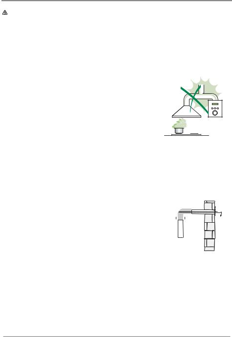
•Do not connect the extractor hood to exhaust ducts carrying combustion fumes (boilers, fireplaces, etc.).
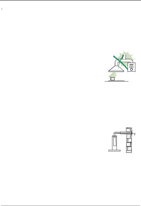
•If the extractor is used in conjunction with nonelectrical appliances (e.g. gas burning
appliances), a sufficient degree of aeration must |
2° |
be guaranteed in the room in order to prevent the |
|
backflow of exhaust gas. The kitchen must have |
|
an opening communicating directly with the open |
|
air in order to guarantee the entry of clean air. |
|
When the cooker hood is used in conjunction with |
|
appliances supplied with energy other than electric, the negative pressure in the room must not exceed 0,04 mbar to prevent fumes being drawn back into the room by the cooker hood.
•In the event of damage to the power cable, it must be replaced by the manufacturer or by the technical service department, in order to prevent any risks.
EN |
|
1 |
|
11 |

•If the instructions for installation for the gas hob specify a greater distance specified above, this has to be taken into account. Regulations concerning the discharge of air have to be fulfilled.
•Use only screws and small parts in support of the hood.
Warning: Failure to install the screws or fixing device in accordance with these instructions may result in electrical hazards.
•Connect the hood to the mains through a two-pole switch having a contact gap of at least 3 mm.
USE
•The extractor hood has been designed exclusively for domestic use to eliminate kitchen smells.
•Never use the hood for purposes other than for which it has been designed.
•Never leave high naked flames under the hood when it is in operation.
•Adjust the flame intensity to direct it onto the bottom of the pan only, making sure that it does not engulf the sides.
•Deep fat fryers must be continuously monitored
during use: overheated oil can burst into flames.
• Do not flambè under the range hood; risk of fire.
• This appliance can be used by children aged from 8 years and above and persons with reduced
physical, sensory or mental capabilities or lack of
experience and knowledge if they have been given supervision or instruction concerning use of the appliance in a safe way and understand the hazards involved. Children shall not play with the appliance. Cleaning and user maintenance shall not be made by children without supervision.
EN |
|
1 |
|
12 |

•“CAUTION: Accessible parts may become hot when used with cooking appliances.”
MAINTENANCE
•Switch off or unplug the appliance from the mains supply before carrying out any maintenance work.
•Clean and/or replace the Filters after the specified time period (Fire hazard).
•The Grease filters must be cleaned every 2 months of operation, or more frequently for particularly heavy usage, and can be washed in a dishwasher.
•The Activated charcoal filter is not washable and cannot be regenerated, and must be replaced approximately every 4 months of operation, or more frequently for particularly heavy usage.
•"Failure to carry out cleaning as indicated will result in a fire hazard".
•Clean the hood using a damp cloth and a neutral liquid detergent.
The symbol  on the product or on its packaging indicates that this product may not be treated as household waste. Instead it shall be handed over to the applicable collection point for the recycling of electrical and electronic equipment. By ensuring this product is disposed of correctly, you will help prevent potential negative consequences for the environment and human health, which could otherwise be caused by inappropriate waste handling of this product. For more detailed information about recycling of this product, please contact your local city office, your household waste disposal service or the shop where you purchased the product.
EN |
|
1 |
|
13 |

WARNINGS - COMPONENTS WARNINGS
This appliance has been designed for use as either an EXTRACTION (ducting to the outside) or RECIRCULATION (filtering) hood. The measurements contained on the drawings in this booklet refer to two models of cooker hood. Therefore, it is essential that you refer to the correct drawing when taking measurements for installation.
-The minimum distance between the cooking surface and the metal grease filters on the underside of the hood must be 650mm.
-This cooker hood must be installed in accordance with the installation instructions and all requirements must be adhered to.
-If the room where the cooker hood is to be used contains a fuel burning appliance such as a central heating boiler then its flue must be of the room sealed or balance flue type.
-If other types of flue or appliances are fitted ensure that there is an adequate supply of air to the room.
-When the range hood and appliance supplied with energy other than electricity are
simultaneously in operation, the negative pressure in the room must not exceed 4 Pa (4x10⁻⁵ bar).
-The ducting system for this appliance must not be connected to any ventilation system which is being used for any other purpose.
-The ducting system for this appliance must not be connected to any existing ventilation system which is being used for any other purpose.
-Do not leave naked flames or carry out flambè cooking under this cooker hood.
-This appliance is not intended for use by persons (including children) with reduced physical, sensory or mental capabilities, or lack of experience and knowledge, unless they have been given supervision or instruction concerning use of the appliance by a person responsible for their safety.
-Children should be supervised to ensure that they do not play with the appliance
CONNECTING THE POWER CABLE TO THE MAINS POWER SUPPLY
Before installation, check that the mains voltage indicated on the rating plate inside the appliance corresponds to the voltage available in your home. If the Hood is not fitted with a plug have a licensed electrician, fit the power cable with a plug of a type approved for the load indicated on the rating plate; when connecting directly to the mains, insert an omni polar circuit breaker with a minimum contact aperture of 3mm and a size suitable for the load in question between the appliance and the mains supply, making sure it is of a type that complies with current regulations.
COMPONENTS
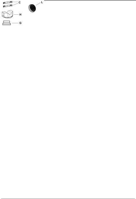
-No 2 Wall Brackets C
-No 1 150-120mm Ducting Spigot G
-No 1 Air Outlet Connection H (Optional)
-No 2 Charcoal Filters L (Optional)
EN |
|
1 |
|
14 |

INSTALLATION
The cooker hood must be installed centrally over a cooking appliance. The minimum distance between the cooking surface and the metal grease filters on the underside of the hood must be at least 650mm.
To install the hood proceed as follows:
1)Drill six 8mm diameter holes at X1-X2-J and insert the plastic rawl plugs supplied as illustrated in fig. 2 ensuring the brackets are fitted as shown in the blow up.
2)Secure the two brackets C to the wall inserting two of the screws supplied through the two holes on line X1-X2 as illustrated in fig. 2.
3)Slide the canopy down the wall to locate the key hole over the washer then secure the canopy to the wall by inserting two of the screws supplied through the two outer holes in the rim of the canopy J1 and J2 as illustrated in fig. 3.
4)EXTRACTION OR RECIRCULATION INSTALLATION:
• EXTRACTION (DUCTED)
When installing the ducted version, connect the hood to the chimney using either a flexible or rigid pipe ø 150 or 120 mm, the choice of which is left to the installer.
•To install a ø 120 mm air exhaust connection, insert the reducer flange 9 on the hood body outlet.
•Fix the pipe in position using sufficient pipe clamps (not supplied).
•Remove any activated charcoal filters.
•RECIRCULATION (FILTERED)
•When the hood is fitted in the recirculation mode the Air Outlet Connection H should be fitted as illustrated in fig. 6.
•Fit the (optional) charcoal filters by repeating the following operation on each side of the motor housing. Place the two key hole slots in the filter L and turn the filter clockwise to lock the filter in position as illustrated in fig. 7.
WARNING: Failure to clean the metal grease filters and replace the charcoal filters regularly represents a possible fire hazard.
Fitting The Chimney
5)FITTING THE UPPER CHIMNEY
Fit the upper chimney A (fig. 8) to the brackets C (fig. 2/ fig. 8) using the four 2.9mm self tapping screws provided. The distance between the fixing holes X1 and X2 is determined by the height of the upper chimney H.
6)FITTING THE LOWER CHIMNEY
To fit the lower chimney B, apply slight force to the two edges to increase the width of the aperture, then insert chimney B into the hood (fig. 9).
EN |
|
1 |
|
15 |

USE - MAINTENANCE USE
The cooker hood functions are controlled by a series of slider or push button switches mounted on the front of the hood and control the worktop lighting and fan motor speeds. This cooker hood will not remove steam.
1)SLIDER SWITCHES
-A switch controls the worktop lighting - ON/OFF.
-A switch controls the fan speeds - OFF/ON-1-2-3.
-The red neon lamp illuminates when the motor is switched ON .
2)PUSH BUTTON SWITCHES
-A switch controls the worktop lighting - ON/OFF.
-A button switches the motor OFF/ON at the low speed setting.
-A button switches the motor to the medium speed setting.
-A button switches the motor to the high speed setting.
-The red neon lamp illuminates when the motor is switched ON.
3)SPEED SETTINGS
-1/Low should be selected when simmering or when using only one pan.
-2/Medium should be selected for cooking when using up to four pans.
-3/High should be selected when frying or cooking food with a strong odour.
MAINTENANCE
N.B. Before carring out any kind of maintenance, cleaning or replacing lamps, disconnect the hood from the mains supply.
1.Lighting
Comprises two (28W - 40W) bulbs. To replace the bulbs, proceed as follows (fig.10): Remove one of the pins at the sides of the lamp cover. Slide the glass towards the side from which the pin has been removed until the opposite edge has been freed, then pull gently downwards. Replace the bults and fit the glass again by repeating the above operations in reverse order.
2.Filters
-The metal grease filter should be cleaned every two months or more frequently if the hood is used consistently and can be cleaned in a dishwasher or by hand using a mild detergent or liquid soap. When replacing, ensure that they are dry.
-The charcoal filter cannot be washed and should be replaced at least every 2 months or more frequently if the hood is used consistently.
3.Cleaning
When cleaning the hood, it is recommended to use a damp cloth and mild liquid household cleaner. Never use abrasive cleaning materials.
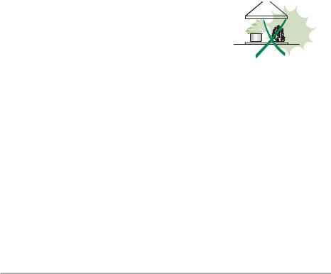
IMPORTANT: When using a gas hob in connection with the cooker hood never leave the burners of the hob uncovered while the hood is in use or when the pans have been removed. It is very important to follow all instructions for cleaning the hood and filters. There could be a possible fire hazard if the filters are not replaced according to these instructions.
ATTENTION: The manufacturer declines all responsibility for any damage or injury caused as a result of not following the instructions for installation, for maintenance and replacement times of filters indicated (in order to avoid a possible risk of fire when the filters are saturated with grease).
EN |
|
1 |
|
16 |
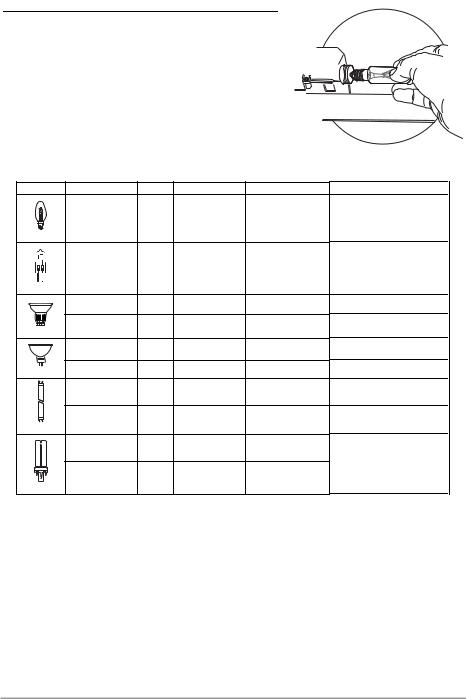
Lighting
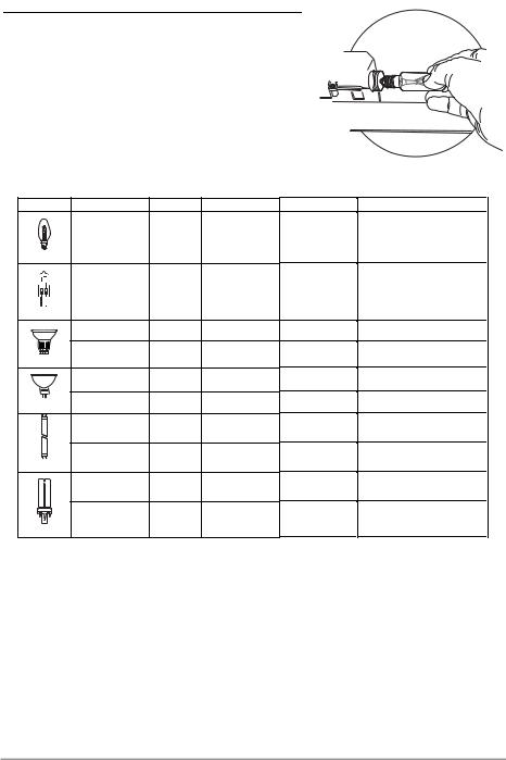
LIGHT REPLACEMENT
28W - 40W incandescent light.
• Remove the screw fixing the Lighting support.
• Pull the Lighting support down.
• Extract the lamp and replace with another of the same type.
• Replace the lighting support in reverse order.
Lamp |
Power (W) |
Socket |
Voltage (V) |
Dimension (mm) |
ILCOS Code |
|
28 |
E14 |
220 – 240 |
104 x 35 |
HSGSB/C/UB-28-220/240-E14 |
|
20 |
G4 |
12 |
33 x 9 |
HSG/C/UB-20-12-G4 |
|
35 |
GU10 |
230 |
51 x 50,7 |
HAGS-35-230-GU10-51/40 |
|
50 |
GU10 |
230 |
51 x 50,7 |
HAGS-35-230-GU10-51/20 |
|
20 |
GU4 |
12 |
40 x 35 |
HRGS-20-12-GU4-35/30 |
|
20 |
GU5.3 |
12 |
46 x 51 |
HRGS-20-12-GU5.3-50/10 |
|
16 |
G13 |
95 |
720 x 26 |
FD--16/40/1B-E--G13--26/720 |
|
18 |
G13 |
57 |
589,8 x 26 |
FD--18/40/1B--E--G13--26/600 |
|
9 |
G23 |
60 (lamp) |
167 x 28 |
FSD-9/27/1B-I-G23 |
|
220-240 (starter) |
||||
|
|
|
|
|
|
|
11 |
G23 |
91 (lamp) |
235,8 x 28 |
FSD-11/40/1B-I-G23 |
|
220-240 (starter) |
||||
|
|
|
|
|
EN |
|
1 |
|
17 |
CONSEILS ET SUGGESTIONS
 Les instructions pour l’utilisation se réfèrent aux différents modèles de cet appareil. Par conséquent, certaines descriptions de caractéristiques particulières pourraient ne pas appartenir spécifiquement à cet appareil.
INSTALLATION
•En aucun cas le fabricant ne peut être tenu pour responsable d’éventuels dommages dus à une installation ou à une utilisation impropre.
•La distance de sécurité minimum entre le plan de
cuisson et la hotte aspirante est de 650 mm (certains modèles peuvent être installés à une hauteur inférieure ; voir le paragraphe concernant les dimensions de travail et l’installation).
• Assurez-vous que la tension de votre secteur correspond à celle indiquée sur la plaque des données appliquée à l’intérieur de la hotte.
•Pour les appareils de Classe I, s’assurer que l’installation électrique de votre intérieur dispose d’une mise à la terre adéquate.
Relier l’aspirateur au conduit de cheminée avec un tube d’un diamètre minimum de 120 mm. Le parcours des fumées doit être le plus court possible.
•Ne pas relier la hotte aspirante aux conduits de cheminée qui acheminent les fumées de combustion (par exemple de chaudières, de cheminées, etc.).
•Si vous utilisez l’aspirateur en combinaison avec des
appareils non électriques (par ex. appareils à gaz), vous |
2° |
devez garantir un degré d’aération suffisant dans la pièce, |
|
afin d’empêcher le retour du flux des gaz de sortie. La |
|
cuisine doit présenter une ouverture communiquant |
|
directement vers l’extérieur pour garantir l’amenée d’air |
|
propre. Si vous utilisez la hotte de cuisine en combinaison avec des appareils |
|
non alimentés à l’électricité, la pression négative dans la pièce ne doit pas |
|
dépasser 0,04 mbar afin d’éviter que la hotte ne réaspire les fumées dans la |
|
pièce. |
|
•Si le cordon d’alimentation est endommagé, veuillez le faire remplacer par le fabricant ou par un service après-vente agréé pour éviter tout risque d’accident.
FR |
|
1 |
|
18 |

•Si les instructions d’installation du plan de cuisson à gaz spécifient une distance supérieure à celle indiquée ci-dessus, veuillez impérativement en tenir compte. Toutes les normes concernant l’évacuation de l’air doivent être respectées.
•Utiliser exclusivement des vis et des petites pièces du type adapté pour la hotte.
Attention : toute installation des vis et des dispositifs de fixation non conforme aux présentes instructions peut entraîner des risques de décharges électriques.
•Brancher la hotte à l’alimentation de secteur avec un interrupteur bipolaire ayant une ouverture des contacts d’au moins 3 mm.
UTILISATION
•Cette hotte aspirante a été conçue exclusivement pour un usage domestique, dans le but d’éliminer les odeurs de cuisine.
•Ne jamais utiliser la hotte pour des objectifs différents de ceux pour lesquels elle a été conçue.
•Ne jamais laisser un feu vif allumé sous la hotte lorsque celle-ci est en fonction.
•Régler l’intensité du feu de manière à l’orienter exclusivement vers le fond de la casserole, en vous assurant qu’il ne déborde pas sur les côtés.
•Contrôler constamment les friteuses durant leur utilisation : l’huile surchauffée risque de s’incendier.
• Ne pas flamber des mets sous la hotte : sous risque de provoquer un incendie.
•Cet appareil n’est pas destiné à être utilisé par des
enfants d’un âge inférieur à 8 ans, ni par des personnes dont les capacités physiques, sensorielles ou mentales sont diminuées ou qui ont une expérience et des connaissances insuffisantes, à moins que ces enfants ou ces personnes ne soient attentivement surveillés et instruits sur la manière d’utiliser cet appareil en sécurité et sur les dangers que cela comporte. Assurez-vous que les enfants ne jouent pas avec cet appareil. Le nettoyage et l’entretien de la part de l’utilisateur ne doivent pas être effectués par des enfants, à moins que ce ne soit sous la surveillance d’une personne responsable.
FR |
|
1 |
|
19 |

•ATTENTION : les parties accessibles peuvent devenir très chaudes durant l’utilisation des appareils de cuisson.
ENTRETIEN
•Avant d’effectuer toute opération de nettoyage et d’entretien, éteindre ou débrancher l’appareil du secteur.
•Nettoyer et/ou remplacer les filtres après le délai indiqué (danger d’incendie).
•Nettoyer les filtres à graisse tous les 2 mois de fonctionnement ou plus souvent en cas d’utilisation particulièrement intense. Ces filtres peuvent être lavés au lave-vaisselle.
•Le filtre à charbon actif ne peut être ni lavé ni régénéré et il doit être remplacé environ tous les 4 mois de fonctionnement ou plus souvent en cas d’utilisation particulièrement intense.
•Effectuer le nettoyage selon les instructions, sous risque d'incendie.
•Nettoyer la hotte avec un chiffon humide et un détergent liquide neutre.
Le symbole  marqué sur le produit ou sur son emballage indique que ce produit ne peut pas être éliminé comme déchet ménager normal. Lorsque ce produit doit être éliminé, veuillez le remettre à un centre de collecte prévu pour le recyclage du matériel électrique et électronique. En vous assurant que cet appareil est éliminé correctement, vous participez à prévenir des conséquences potentiellement négatives pour l'environnement et pour la santé, qui risqueraient de se présenter en cas d’élimination inappropriée. Pour toute information supplémentaire sur le recyclage de ce produit, contactez votre municipalité, votre déchetterie locale ou le magasin où vous avez acheté ce produit.
FR |
|
2 |
|
20 |
ATTENTION - COMPOSANTS ATTENTION
Cet appareil a été conçu pour être employé en version ASPIRANTE (évacuation de l'air vers l'extérieur) ou en version RECYCLAGE (air conduite vers l'intérieur).
-La distance minimum entre le plan de cuisson et la partie inférieure de la hotte doit être au moins de 650mm.
-Il faut prévoir une aération convenable de la pièce lorsque la hotte et les appareils ali-
mentés avec énergie différente de celle éléctrique sont utilisés en même temps; la pression négative de la pièce ne doit pas dépasser 4Pa (4x10⁻⁵ bar).
-L'air recueillie ne doit pas être dirigée dans un conduit utilisé pour la décharge des fumées des appareils alimentés avec énergie différente de celle éléctrique.
-Respecter les prescriptions des autorités compétentes relatives à la décharge de l'air à evacuer.
-Eviter la présence de flammes libres dans l'espace au dessous de la hotte.
-La hotte a été construite avec isolement en classe II, donc il n'y a pas besoin de la relier à la terre.
-Avant d'effectuer toutes les opérations d'entretien, débrancher l'appareil de l'alimentation éléctrique.
-Cet appareil ne doit pas être utilisé par des personnes (y compris les enfants) ayant des capacités psychiques, sensorielles ou mentales réduites, ni par des personnes n’ayant pas l’expérience et la connaissance de ce type d’appareils, à moins d'être sous le contrôle et la formation de personnes responsables de leur sécurité.
-Les enfants doivent être surveillés pour s'assurer qu'ils ne jouent pas avec l'appareil.
BRANCHEMENT DU CÂBLE ÉLECTRIQUE AU RÉSEAU
Avant l’installation, vérifier que la tension du réseau indiquée sur la plaquette se trouvant à l’intérieur de l’appareil correspond à la tension électrique de votre habitation. Si la hotte n’est pas munie de fiche électrique, monter une fiche à norme sur le câble d’alimentation qui soit adaptée à la tension indiquée sur la plaquette des caractéristiques. En cas de branchement électrique direct sur le réseau, il faudra placer un interrupteur omnipolaire entre l’appareil et le réseau ayant une ouverture minimum entre les contacts de 3 mm, et adapté à la tension et répondant aux normes en vigueur.
COMPOSANTS
-2 brides C
-1 bride de réduction G
-1 raccord filtrant H (optionnel)
-2 filtres charbon actif L (optionnel)
FR |
|
2 |
|
21 |

INSTALLATION
La hotte doit être assemblée au centre du plan de cuisson. La distance minimum entre le plan de cuisson et la surface inférieure de la hotte doit être de 650mm.
Pour l'assemblage de la hotte procéder de la manière suivante:
1)Faire n°6 trous (X1-X2-J) de 8mm respectant les chiffres indiqués à la fig. 1.
2)Pour les différents assemblages utiliser les vis et les vis tamponnées fournies..
3)Bloquer l'étrier C (fig. 2) à la paroi dans les trous X1-X2.
4)Fixer la hotte à la paroi dans les trous J1 et J2 (fig. 3) .
5)Assemblage ASPIRANTE ou FILTRANT.
• ASPIRANTE
En cas d’installation en version aspirante, brancher la hotte à la tuyauterie de sortie via un tube rigide ou flexible de ø 150 ou 120 mm, au choix de l’installateur.
•En cas de branchement avec un tube de ø120 mm, insérer le flasque de réduction 9 sur la sortie du corps de la hotte.
•Fixer le tube par des colliers appropriés. Le matériau nécessaire n’est pas fourni.
•Retirer les éventuels filtres anti-odeur au charbon actif.
•FILTRANT (OPTION)
-Insérer le Raccord Sortie Air H (fig. 6).
-Assembler les filtres charbon actif L (fig. 7) en les centrant dans le support moteur M et les bloquer en tournant dans sens horaire (environ 10°) jusqu'à l'arret. Pour les opérations de démontage faire les opérations inverses.
6)Fixer la cheminée supérieure A (fig. 8) à l'étrier C (fig. 2/fig. 8) utilisant 4 vis autotaraudeuses de Ø 2,9mm en dotation. La distance entre les alésages de fixation X1 et X2 est déterminée par la hauteur de la cheminée supérieure H.
7)Appliquer frontalement la cheminée inférieure B (fig. 9) en élargissant légèrement les deux parties latérales et l'insérer ensuite dans la hotte (fig. 9).
FR |
|
2 |
|
22 |

UTILISATION - ENTRETIEN UTILISATION
Nous vous recommandons de faire fonctionner l'appareil quelque temps avant de procéder à la cuisson de n'importe quel aliment, de le laisser fonctionner encore pendant 15 minutes après la cuisson et de toute manière tant que les odeurs n'auront pas disparu.
1)Bandeau de commandes avec interrupteurs
-Un interrupteur qui commande l'allumage de l'installation d'éclairage.
-Un interrupteur pour commuter les trois vitesses d'exercice.
-Un voyant général de signalisation moteur en service.
2)Bandeau de commandes avec touches
-Une touche qui commande l'allumage du moteur en première vitesse, indiquée pour une circulation d'air continue particulièrement silencieuse, en présence de faibles vapeurs de cuisson.
-Une touche qui commande le moteur en deuxième vitesse, indiquée dans la plupart des conditions d'emploi vu l'excellent rapport entre le débit d'air traité et le niveau de bruit.
-Une touche qui commande le moteur en troisième vitesse, indiquée en cas d'importantes émissions de vapeurs de cuisson, également pendant des périodes prolongées.
-Une touche qui commande l'allumage de l'installation d'éclairage.
ENTRETIEN
N.B. Pour n'importe quelle opération d'entretien et de réparation débranchez l'appareil.
1. Eclairage
Il est constitué par deux lampes de (28W - 40W). Pour effectuer un remplacement, suivre les instructions suivantes (fig.10): Retirer l'un des goujons qui se trouvent sur les côtés du plafonnier. Faire coulisser le verre sur le côté sans le goujon, jusqu'à dégager la pointe opposée, puis tirer légèrement vers le bas. Remplacer les lampes et remonter le verre en effectuant les opérations décrites ci-dessus à rebours.
2. Filtres
A des intervalles plus ou moins fréquents en fonction de leur utilisation, mais en tout cas une fois tous les 2 mois, les filtres métalliques doivent être lavés dans le lave-vaisselle ou à la main dans de l'eau tiède savonneuse (les filtres au charbon actif ne doivent jamais etre lavés et doivent être remplacés tous les 2 mois).
3. Nettoyage
Pour ce qui concerne le nettoyage externe de la hotte, utiliser un chiffon humide et de l'alcool ou d'autres produits appropriés. N'employez pas de produits abrasifs.
IMPORTANT: Il est obligatoire d'effectuer les opérations de nettoyage de la hotte et des filtres, ainsi que de les remplacer périodiquement selon nos instructions pour éviter les risques d'incendie.
ATTENTION: Le fabricant décline toute résponsabilité pour les dommages provoqués par le non entretien des filtres anti-graisse (nettoyage tous les 2 mois) ainsi que par le non replacement périodiques des filtres à charbon et par le non respect des instructions de montage et de branchement.
FR |
|
2 |
|
23 |
Eclairage
REMPLACEMENT LAMPES
Lampe à incandescence de 28W - 40W
• Retirer la vis qui fixe le Support éclairage.
• Tirer le Support vers le bas.
• Extraire la Lampe du Support.
• Remplacer par une nouvelle lampe possédant les mêmes caractéristiques.
• Remonter le Support éclairage.
Ampoule |
Absorption (W) |
Culot |
Voltage (V) |
Dimensions (mm) |
Code ILCOS |
|
28 |
E14 |
220 – 240 |
104 x 35 |
HSGSB/C/UB-28-220/240-E14 |
|
20 |
G4 |
12 |
33 x 9 |
HSG/C/UB-20-12-G4 |
|
35 |
GU10 |
230 |
51 x 50,7 |
HAGS-35-230-GU10-51/40 |
|
50 |
GU10 |
230 |
51 x 50,7 |
HAGS-35-230-GU10-51/20 |
|
20 |
GU4 |
12 |
40 x 35 |
HRGS-20-12-GU4-35/30 |
|
20 |
GU5.3 |
12 |
46 x 51 |
HRGS-20-12-GU5.3-50/10 |
|
16 |
G13 |
95 |
720 x 26 |
FD--16/40/1B-E--G13--26/720 |
|
18 |
G13 |
57 |
589,8 x 26 |
FD--18/40/1B--E--G13--26/600 |
|
9 |
G23 |
60 (ampoule) |
167 x 28 |
FSD-9/27/1B-I-G23 |
|
220-240 (starter) |
||||
|
|
|
|
|
|
|
11 |
G23 |
91 (ampoule) |
235,8 x 28 |
FSD-11/40/1B-I-G23 |
|
220-240 (starter) |
||||
|
|
|
|
|
FR |
|
2 |
|
24 |

EMPFEHLUNGEN UND HINWEISE
Diese Gebrauchsanleitungen beziehen sich auf die verschiedenen Modelle der Abzugshaube. Darum kann es möglich sein, dass die Beschreibung bestimmter Merkmale für das vorliegende Gerät nicht zutrifft.
INSTALLATION
•Der Hersteller haftet nicht für etwaige Schäden, die durch die fehlerhafte Installation oder falschen Gebrauch entstehen könnten.
•Der min. Sicherheitsabstand zwischen Kochfeld und Abzugshaube beträgt 650 mm (einige Modelle können auch niedriger installiert werden; siehe Absatz Installation).
• Kontrollieren Sie, ob die Netzspannung den Daten des Typenschilds im Innern der Haube entspricht.
• Für Geräte der Klasse I muss kontrolliert werden, ob das häusliche Versorgungsnetz korrekt geerdet ist.
Die Absaughaube mit Hilfe eines Rohrs mit einem Mindestdurchmesser von 120 mm mit dem Rauchabzug verbinden. Der Verlauf des Rauchabzugs soll so kurz wie möglich sein.
•Die Abzugshaube darf nicht an einen Schacht angeschlossen werden, in den Rauchgase geleitet werden (z. B. von Heizkessel, Kaminen, usw.).
•Falls in dem Raum neben dem Abzug auch nicht mit Strom betriebene Geräte (zum Beispiel
Gasgeräte) eingesetzt werden, muss für eine |
2° |
ausreichende Belüftung gesorgt werden, damit der |
|
Rückfluss der Abgase verhindert wird. Die Küche |
|
muss eine direkte Öffnung nach Außen aufweisen, |
|
damit ein ausreichender Luftaustausch |
|
gewährleistet wird. Wird die Abzugshaube |
|
zusammen mit nicht mit Strom betriebenen Geräte eingesetzt, darf der |
|
Unterdruck im Raum 0,04 mbar nicht überschreiten, damit die Abgase nicht |
|
wieder angesaugt werden. |
|
•Schadhafte Kabel müssen durch den Hersteller oder vom Kundendienst ausgewechselt werden, damit jedes Risiko ausgeschlossen wird.
DE |
|
2 |
|
25 |
•Falls die Montageanweisungen für die gasbetriebene Kochmulde einen größeren Abstand vorschreiben, als der oben angegebene, muss diese Vorgabe befolgt werden. Es sind sämtliche Abluftvorschriften zu beachten.
•Nur für die Abzugshaube geeignete Schrauben und Kleinteile verwenden. Achtung: Werden die Schrauben und Befestigungselemente nicht entsprechend der vorliegenden Anleitungen verwendet, besteht Stromschlaggefahr.
•Die Abzugshaube mittels zweipoligem Schalter mit einer Öffnung der Kontakte von mindestens 3 mm an das Netz anschließen.
GEBRAUCH
•Die Abzugshaube wurde ausschließlich für den häuslichen Gebrauch entwickelt, um Kochdünste zu beseitigen.
•Die Haube darf nur für die ihr zugedachten Zwecke benutzt werden.
•Unter der eingeschalteten Haube keine offenen Flammen benutzen.
•Die Flamme so regulieren, dass sie nicht über den Boden des Kochgeschirrs hinausreicht.
•Fritteusen müssen während des Gebrauchs ständig überwacht werden: überhitztes Öl könnte
sich entzünden.
• Auf keinen Fall unter der Haube flambieren: Brandgefahr.
•Kinder ab 8 Jahren und Personen mit
eingeschränkten physischen, sensorischen oder psychischen Fähigkeiten, oder mit mangelnden Erfahrungen oder Kenntnissen dürfen nicht mit dem Gerät umgehen, es sei denn, sie werden von einer für ihre Sicherheit verantwortlichen Person beaufsichtigt oder angeleitet. Sicherstellen, dass Kinder nicht mit dem Gerät herumspielen können. Reinigungsund Wartungsarbeiten dürfen nicht von unbeaufsichtigten Kindern durchgeführt werden.
DE |
|
2 |
|
26 |

•ACHTUNG: Die zugänglichen Teile können während des Gebrauchs der Kochgeräte sehr heiß werden.
WARTUNG
•Vor Reinigungsoder Wartungsarbeiten am Gerät, muss dieses ausgeschaltet und spannungslos gemacht werden.
•Die Filter stets nach den angegebenen Intervallen reinigen oder auswechseln (Brandgefahr).
•Die Fettfilter sind alle 2 Monate oder bei intensiver Nutzung öfter zu reinigen und können in der Spülmaschine gespült werden.
•Der Aktivkohlefilter ist weder waschbar, noch regenerierbar und muss bei normalem Betrieb zirka alle 4 Monate oder auch öfter ausgewechselt werden, je nach Intensität des Gebrauchs.
•„Wenn die Reinigung nicht nach den Anweisungen durchgeführt wird, besteht Brandgefahr“.
•Die Haube mit einem feuchten Lappen und einem neutralen Reinigungsmittel abwischen.
Das Symbol  am Produkt oder auf der Verpackung weist darauf hin, dass das Gerät nicht als normaler Hausmüll entsorgt werden darf. Das ausrangierte Gerät muss vielmehr bei einer speziellen Sammelstelle für elektrische und elektronische Geräte abgegeben werden. Mit der vorschriftsmäßigen Entsorgung des Gerätes trägt der Benutzer dazu bei, schädliche Auswirkungen auf Umwelt und Gesundheit zu vermeiden. Weitere Informationen zum Recycling dieses Produktes können bei der zuständigen Behörde, der örtlichen Abfallbeseitigung oder bei dem Händler, der das Gerät verkauft hat, eingeholt werden.
DE |
|
2 |
|
27 |

HINWEIS - KOMPONENTEN HINWEISE
Dieses Gerät ist sowohl als ABLUFTHAUBE (Abführung der Luft nach außen), als auch als UMLUFTHAUBE (Filtrierung der Dünste im Innern) verwendbar.
-Der Mindestabstand zwischen Kochfeld und Unterseite der Haube soll 650 mm betragen.
-Wenn die Luft nach Außen abgeführt wird (Abluftbetrieb), muss die Haube nach den folgenden Anweisungen installiert werden.
-Bei gleichzeitigem Betrieb der Dunstabzugshaube im Abluftbetrieb und Feuerstätten darf im Aufstellraum der Feuerstätte der Unterdruck nicht größer als 4 Pa (4x10⁻⁵ bar) sein.
-Das Abluftrohr der Haube darf keinesfalls an den Rauchabzug von Feuerstätten angeschlossen werden.
-Die Abluftvorschriften der zuständigen Behörden beachten.
-Niemals eine Flamme unter der Dunsthaube unbedeckt lassen.
-Das Gerät entspricht der Schutzklasse II und muss daher nicht geerdet werden.
-Vor Wartungsarbeiten muss das Gerät spannungslos gemacht werden.
-Dieses Gerät darf nicht von Personen, auch Kindern, mit verminderten psychischen, sensorischen und geistigern Fähigkeiten, oder von Personen ohne Erfahrung und Kenntnisse benutzt werden, sofern sie nicht von für ihre Sicherheit verantwortlichen Personen beaufsichtigt und beim Gebrauch des Geräts angeleitet werden.
-Kinder dürfen sich nicht unbeaufsichtigt in der Nähe des Geräts aufhalten und auf keinen Fall mit dem Gerät spielen.
ANSCHLUSS DES STROMKABELS AN DAS NETZ
Vor der Installation muss kontrolliert werden, ob die am Typenschild im Geräteinnern angegebene Netzspannung der Spannung Ihres Haushalts entspricht. Falls das Gerät ohne Stecker ist, muss das Kabel mit einem genormten, für die am Typenschild angegebene Last ausreichenden Stecker versehen werden; bei direktem Anschluss an das Netz muss ein korrekt dimensionierter allpoliger Schalter mit einer Mindestkontaktöffnung von 3 mm zwischengeschaltet werden, der den einschlägigen Vorschriften entspricht.
KOMPONENTEN
-2 Wandhalterungen C
-1 Reduzierflansch G
-1 Filterstutzen H (Option)
-2 Aktivkohlefilter L (Option)
DE |
|
2 |
|
28 |

MONTAGE
Die Haube muss mittig über dem Kochfeld installiert werden. Der Mindestabstand zwischen Kochfeld und Unterseite der Haube soll 650 mm betragen.
Für die Installation wie folgt vorgehen:
1)6 Löcher (X1-X2-J) mit 8 mm Durchmesser nach den Maßangaben der Abb.1 ausführen.
2)Die für die jeweilige Montage mitgelieferten Schrauben und Dübel verwenden.
3)Die Wandhalterungen C (Abb. 2) mittels der Bohrungen X1-X2 an der Wand befestigen.
4)Die Haube mittels der externen Bohrlöcher J1 und J2 (Abb. 3) an der Wand befestigen.
5)Montage als ABLUFTHAUBE oder UMLUFTHAUBE:
ABLUFTBETRIEB
Bei Abluftbetrieb kann die Haube vom Installateur wahlweise mittels Rohr oder Schlauch (ø 150 oder 120 mm) an den Auslass angeschlossen werden.
-Bei Verwendung eines Anschlussrohres ø 120 den Reduzierflansch 9 am Haubenausgang anbringen.
-Das Rohr mit passenden Rohrschellen fixieren. Das hierzu erforderliche Material wird nicht mitgeliefert.
-Eventuell vorhandene Aktivkohlefilter ausbauen.
UMLUFTBETRIEB (OPTION)
-Den Filterstutzen H einbauen (Abb. 6).
-Den Aktivkohlefilter L (Abb.7) einlegen und durch Drehen im Uhrzeigersinn (um zirka 10°) einrasten lassen. Zum Ausbauen in umgekehrter Reihenfolge vorgehen.
Montage der Kamine:
6)Befestigen Sie das obere Kaminteil A (Abb. 8) mit den vier beiliegenden, selbstschneidenden Schrauben Ø 2,9 mm an den Halterungen C (Abb.2/Abb.8). Der Abstand zwischen den Bohrlöchern X1 und X2 hängt von der Höhe des oberen Kaminteils H ab.
7)Um das untere Kaminteil B (Abb. 9) anzubringen die beiden Seitenteile leicht auseinanderbiegen und dann an der Haube einsetzen (Abb. 9).
DE |
|
2 |
|
29 |

BEDIENUNG - WARTUNG
BEDIENUNG
Die Dunsthaube ist, je nach Modellart, mit verschiedenen Schiebeschaltern oder Drucktasten an der Haubenfront ausgestattet, mit denen die Arbeitsflächenbeleuchtung und die Motorgeschwindigkeit geschaltet werden .
1)Schiebeschaltung
Ein Schalter schaltet die Beleuchtung ein. Ein Schalter steuert die drei Gebläsestufen.
Eine Kontrolllampe zeigt den Motorbetrieb an.
2)Drucktastenschaltung
Ein Schalter schaltet die Beleuchtung ein
Ein Schalter schaltet den Motor ein und aus ( niedrigste Stufe). Ein Schalter schaltet die mittlere Stufe ein.
Ein Schalter schaltet die höchste Stufe ein.
Die rote Kontrolllampe zeigt an, wenn der Motor eingeschaltet ist.
3)Geschwindigkeitsstufen
1 / niedrig bei Benutzung einer Kochplatte
2 / mittel beim Gebrauch bis zu vier Kochplatten
3 / hoch beim Braten oder bei starkem Kochdunst
WARTUNG
N.B. Vor sämtlichen Wartungsund Reparaturarbeiten bzw. vor Auswechseln der Lampen
muss die Stromzufuhr zum Gerät unterbrochen werden.
1. Beleuchtung
Die Beleuchtung besteht aus zwei Lampen zu (28W - 40W). Beim Austausch einer Lampe ist wie folgt vorzugehen (Abb.10): einen der Stifte an der Lampenabdeckungsseite entfernen. Dann das Glas auf die Seite ohne Stift schieben, bis das gegenüberliegende Ende frei liegt und etwas senken. Die Lampen austauschen und die Glasabdeckung in umgekehrter Reihenfolge wieder montieren.
2. Filter
Je nach Einsatzhäufigkeit müssen die Metallfettfilter in angebrachten Zeitabständen (maximal alle 2 Monate) demontiert und mit warmem Seifenwasser bzw. im Geschirrspüler gereinigt und trocken wieder montiert werden (Aktivkohlefilter dürfen keinesfalls gewaschen werden, sondern sind alle 2 Monate auszuwechseln).
3. Pflege
Zur Außenreinigung der Haube ein mit Alkohol oder zweckentsprechenden, handelsüblichen Reinigungsmitteln angefeuchtetes Tuch verwenden. Scheuermittel sind zu vermeiden.
WICHTIG: Offene Flammen schädigen die Filter; deshalb wird davon abgeraten, Gaskochstellen ohne Kochtopf brennen zu lassen. Die Maßnahmen zur Reinigung der Haube bzw. der Filter und das Auswechseln der Filter haben verbindlich gemäß unseren Vorschriften und in regelmäßigen Zeitabständen zu erfolgen, um Brandgefahr zu vermeiden.
ACHTUNG: Die Herstellerfirma übernimmt keine Haftung für Schäden, die durch unterlassene Wartung des Fettfilters (alle zwei Monate auswaschen), unterlassenes Auswechseln des Aktivkohlefilters und Nichtbeachtung der obengenannten Anleitungen zur Montage und zum Elektronanschluss entstehen.
DE |
|
3 |
|
30 |
 Loading...