

Page 1
kÉï=~ë=çÑW
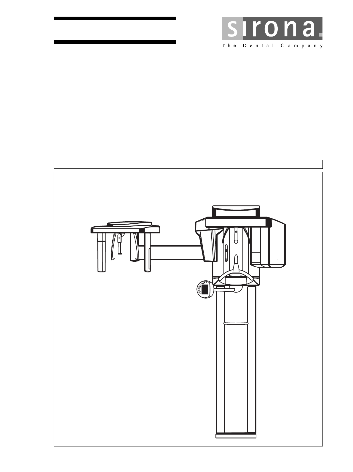
ORTHOPHOS
NMKOMNQ
loqelmelp=ud=Pa=L=`ÉéÜ
êÉ~Çó
loqelmelp=ud=Pa
fелн~дд~нбзе=oЙимбкЙгЙенл= =
L=`ÉéÜ
bеЦдблЬ
Page 2

Sirona Dental Systems GmbH
Installation Requirements
General information
About this document
This document describes the installation requirements for
the ORTHOPHOS XG 3D / Ceph and ORTHOPHOS XG
ready
/ Ceph X-Ray unit.
3D
Their subsequent installation is described in the Installation
Instructions, ORTHOPHOS XG 3D / Ceph REF 63 03 452
and ORTHOPHOS XG 3D
ready
/ Ceph REF 59 87 651.
kÉï=~ë=çÑW=
Changes since the last version 07.2012:
Chapter or section, page
1.4 IT hardware ........................................................... 12
3.5 Technical data ....................................................... 36
NMKOMNQ
2 D3352.021.03.04.02
63 03 551 D3352
Page 3

Sirona Dental Systems GmbH
Installation Requirements ORTHOPHOS XG 3D
List of Contents
1 Installation requirements checklist .................................................................................... 5
1.1 Purpose of this checklist .............................................................................. 6
1.2 Executing persons/companies..................................................................... 7
1.3 Structural prerequisites................................................................................ 9
1.4 IT hardware.................................................................................................. 12
1.5 Network........................................................................................................ 15
1.6 Data processing........................................................................................... 16
1.7 Action list ..................................................................................................... 18
2 Preparations.......................................................................................................................... 19
2.1 Safety........................................................................................................... 20
2.2 Possibilities of Installation............................................................................ 21
2.3 Mounting options ......................................................................................... 22
2.4 Principle of On-site Installation .................................................................... 23
2.5 Emergency Stop (if required by law)............................................................ 24
2.6 On-site Installation for PC/Networks............................................................ 25
2.7 For USA and Canada .................................................................................. 26
bеЦдблЬ
3 Dimensions, technical data ................................................................................................. 27
3.1 Dimensions of the ORTHOPHOS XG 3D / 3D
3.2 Dimensions of the ORTHOPHOS XG 3D / 3D
on Floor stand ............................................................................................. 30
3.3 Dimensions of the ORTHOPHOS XG 3D / 3D
Ceph left ..................................................................................................... 32
3.4 Dimensions of the ORTHOPHOS XG 3D / 3D
Ceph right ................................................................................................... 34
3.5 Technical data ............................................................................................. 36
ready
1:20 ............................. 28
ready
1:20
ready
/ Ceph 1:20
ready
/ Ceph 1:20
4 Electromagnetic compatibility ............................................................................................ 37
4.1 Accessories ................................................................................................. 38
4.2 Electromagnetic emission............................................................................ 39
4.3 Immunity to interference .............................................................................. 40
4.4 Working clearances ..................................................................................... 42
63 03 551 D3352
D3352.021.03.04.02
3
Page 4

Sirona Dental Systems GmbH
Installation Requirements ORTHOPHOS XG 3D
4 D3352.021.03.04.02
63 03 551 D3352
Page 5
1 Installation requirements checklist
loqelmelp=ud=PaLPa
1.1 Purpose of this checklist ........................................................................................................ 6
1.2 Executing persons/companies ............................................................................................... 7
1.3 Structural prerequisites .......................................................................................................... 9
1.4 IT hardware ........................................................................................................................... 12
1.5 Network ................................................................................................................................. 16
1.6 Data processing ..................................................................................................................... 17
1.7 Action list ............................................................................................................................... 19
êÉ~Çó
63 03 551 D3352
D3352.021.03.04.02
5
Page 6

1 Installation requirements checklist Sirona Dental Systems GmbH
Installation Requirements ORTHOPHOS XG 3D/3D
ready
1.1 Purpose of this checklist
We recommend checking the local conditions 4 weeks prior to the date of installation.
This will help ensure a smooth workflow when the ORTHOPHOS XG 3D/3D
ready
unit is actually ins-
talled. The most important points to be observed are specified in the checklist contained in this
document.
6 D3352.021.03.04.02
63 03 551 D3352
Page 7
Sirona Dental Systems GmbH 1 Installation requirements checklist
Installation Requirements ORTHOPHOS XG 3D/3D
ready
1.2 Executing persons/companies
List of local executing persons/companies:
Dealer:
Date of installation
inspection :
Present/company:
Present/company:
Present/company:
Installation site / Practice/
clinic
Last name, first name:
Street:
City/State/Postal (ZIP) code:
Phone:
E-mail: @
Special field of system
owner:
63 03 551 D3352
D3352.021.03.04.02
7
Page 8
1 Installation requirements checklist Sirona Dental Systems GmbH
Installation Requirements ORTHOPHOS XG 3D/3D
ready
1.2 List of executing persons/companies
List of contact persons on-site:
Function First name / Last name: Phone: Cell phone E-mail
Service engineer
IT specialist
Dental specialist
Administrator
Expert
Clinic technician
Prof.
Dentist
Scheduled day/date of installation:
Time:
Possible postponement to day/date:
Time:
8 D3352.021.03.04.02
63 03 551 D3352
Page 9
Sirona Dental Systems GmbH 1 Installation requirements checklist
Installation Requirements ORTHOPHOS XG 3D/3D
,
ready
1.3 Structural prerequisites
Transport path:
• Clarify and/or walk along unit transport path from delivery location to
installation site, measuring doorways and passageways (Dimensions/
weight, see 3.5)
Transport path OK?
• Elevator available?
• Provide appropriate transport personnel!
• Person responsible:
• Remarks/Tasks:
yes no
yes no
yes no
63 03 551 D3352
D3352.021.03.04.02
9
Page 10
1 Installation requirements checklist Sirona Dental Systems GmbH
ATTENTION
Installation Requirements ORTHOPHOS XG 3D/3D
,
ready
1.3 Structural prerequisites
Transpor t path :
• Transport path:
Unit location:
Building number:
Room name/number:
• Is the room large enough? (see 3.1)
• Is a radiation protection plan available?
• Measured room height at least 2100 mm (82 3/4“)?
• Maximum unit height without floor stand 2249 mm (88 1/2“)
• Maximum unit height with floor stand 2279 mm (89 1/4“)
yes no
yes no
yes no
• Floor heating installed?
• If so, use 2nd wall bracket
• Carpeting at system site?
If so, remove carpeting underneath system.
• Info available on wall material?
Perform test drilling if necessary!!
• Required extraction forces (wall plugs see 2.2) ensured?
If the condition of the wall is not sufficient, a floor stand can be used.
The upper wall fastening for immobilizing the unit is absolutely essential
when installing it on the floor stand!
• Installation on the wall with or without floor stand? (see 2.3)?
• Intermediate storage possibilities available for styrofoam parts?
The unit should be brought to the installation site with the styrofoam parts,
one of the installation aids should also be present. They must be temporarily
stored until they are shipped.
• Remarks/Tasks:
yes no
yes no
yes no
yes no
with without
yes no
10 D3352.021.03.04.02
63 03 551 D3352
Page 11
Sirona Dental Systems GmbH 1 Installation requirements checklist
Installation Requirements ORTHOPHOS XG 3D/3D
,
ready
1.3 Structural prerequisites
Electrical connection of the ORTHOPHOS XG
2
• Fuse protection of hard-wired unit connection 3x2.5mm
B25A, 3x1.5mm
ORTHOPHOS XG 3D/3D
2
(16AWG) B 16A/20A may be connected only to
ready
.
• Internal line impedance checked? (max. 0,8 Ohm)
(14 AWG) 230/
yes no
yes no
• 2. Protective ground wire installed?
If no 2nd protective ground wire is installed, one must be retrofitted!
• Are other large electrical devices installed nearby (e.g. air conditioning units,
fan motors)?
If so, what kind of devices (EMC influences)?
• Distance from ORTHOPHOS XG 3D/3D
ready
? _________m
• Remarks/Tasks:
Type of remote control installation
• Select the type of remote control required (see 2.2 ):
– In the room
– Outside without coiled cable
– Outside with coiled cable
• Conduit available?
yes no
yes no
yes
yes
yes
yes no
no
no
no
• Diameter Conduit? (Diameter mind. 10 mm (3/8“)) _________mm
• Distance Conduit? (Distance max. 13 m (512“)) _________m
• Remarks/Tasks:
63 03 551 D3352
D3352.021.03.04.02
11
Page 12

1 Installation requirements checklist Sirona Dental Systems GmbH
Installation Requirements ORTHOPHOS XG 3D/3D
ready
1.4 IT hardware
Minimum requirements for RCU/visualization-PC
(not included in the scope of supply)
Minimum requirements: Recommendation: Minimum
Operating
system:
Windows 7 Professional
(64-Bit)
Windows 7 Ultimate 64bit
Processor: DualCore ab 2 GHz Quadcore ab 2 GHz
Hard disk: Min. 500 GB
free storage space
Min. 1 TB
free storage space
RAM: 4 GB 4 GB
Drives: CD/DVD ROM CD/DVD ROM
Graphics
system:
external, > 512MB,
min. resolution 1280x1024
16.7 mil. colors (TrueColor)
Shader Model 3 for Advanced
Rendering in GALILEOS
Implant
external, > 512MB,
min. resolution 1280x1024
16.7 mil. colors (TrueColor)
Shader Model 3 for Advanced
Rendering in GALILEOS
Implant
Screen: Suitable for diagnostics Suitable for diagnostics
Network Card: Network RJ45, 100MBit/s Network RJ45, 1GBit/s
Recommen
dation
• Remarks/Tasks:
12 D3352.021.03.04.02
63 03 551 D3352
Page 13
Sirona Dental Systems GmbH 1 Installation requirements checklist
Installation Requirements ORTHOPHOS XG 3D/3D
ready
1.4 IT hardware
Treatment centers/RCU
• Is a diagnostic monitor available?
At least one diagnostic monitor must be available in the practice.
• Number of treatment centers planned (viewing PCs)
It is advisable to locate a treatment center PC (viewing PC) near the
ORTHOPHOS XG 3D/3D
exposure.
ready
for the purpose of readying the unit for
_________piece
• Plan/determine location of RCU (room)
• Is a switch installed?
1GBit
• Remarks/Tasks:
yes no
yes
100MBit
no
63 03 551 D3352
D3352.021.03.04.02
13
Page 14
1 Installation requirements checklist Sirona Dental Systems GmbH
ATTENTION
Installation Requirements ORTHOPHOS XG 3D/3D
ready
1.4 IT hardware
SQL/Fileserver
• Are SIDEXIS databases already installed?
• f so, which version of the SIDEXIS database?
(Patients.paf, Pdata.mdb, SQL-Express or SQL)
• Is migration necessary?
• SQL Server installed?
Microsoft SQL Express is included in the scope of supply!
yes no
yes no
yes
no
– SQL Server version
– SQL Server name
• File server installed (separate server for image database only)?
– Windows release with full access
– Operating system/version
– Name of computer
– IP adress
– Processor speed (clock frequency)
– Available RAM?
– Available hard disk storage?
_________
_________
yes
yes
_________
_________
____ . ____ . ____ . ____
_________
________GB
________GB
• Estimated number of exposures (approx.) /
Approx. 500 MB per volume are currently stored in the database! _________
– Per month?
– Month x 12 = per year
– Approx. required storage space
– Depending on this, is a backup system available?
_________
_________
_______GB
yes
no
no
no
Network Attached Storage (NAS) units .
The use of LINUX based Network Attached Storage (NAS) units for PDATA
can cause problems. Adjustment problems with these units have
occurred in the past.
• Remarks/Tasks:
14 D3352.021.03.04.02
– Is a backup system planned?
yes
no
63 03 551 D3352
Page 15

Sirona Dental Systems GmbH 1 Installation requirements checklist
NOTE
i
Installation Requirements ORTHOPHOS XG 3D/3D
ready
1.5 Network
Network
• The entire network should be configured with 1GBit Ethernet!
yes
–Cat 5 100Mbit/sec
no
– Cat 5e/Cat 6 1 Gbit/sec
• Network connection installed for ORTHOPHOS XG 3D/3D
• "Network connection installed on all treatment centers?
• "Network connection installed for RCU?
It is advisable to locate a treatment center PC near the
ready
ORTHOPHOS XG 3D/3D
for the purpose of readying the unit for
exposure.
• Network configuration plan available?
• "Have the network jacks been certified?
• "Network certificate available?
• "Network installation company?
• Remarks/Tasks:
ready
yes
?
yes no
yes no
yes no
yes no
yes no
yes no
no
63 03 551 D3352
D3352.021.03.04.02
15
Page 16

1 Installation requirements checklist Sirona Dental Systems GmbH
ATTENTION
Installation Requirements ORTHOPHOS XG 3D/3D
ready
1.6 Data processing
IP addresses/Firewall
• TCP/IP address range ____ . ____ . ____ . ____ - ____ . ____ . ____ . ____
• Subnet mask ____ . ____ . ____ . ____
• Are addresses already defined/present?
• Is there a DHCP server (dynamic TCP/IP address assignment)?
yes no
yes no
A static address is required for the ORTHOPHOS XG 3D/3D
ready
! It must
not lie in the dynamic address range!
ready
• ORTHOPHOS XG 3D/3D
: ____ . ____ . ____ . ____
•RCU: ____ . ____ . ____ . ____
• Viewing PCs: ____ . ____ . ____ . ____ - ____ . ____ . ____ . ____
• Standard gateway: ____ . ____ . ____ . ____
• "Antivirus software installed?
yes
no
Name:
• Is a firewall installed?
– Software or hardware firewall?
yes
SW
no
HW
The following ports must be open for the SIDEXIS and for unit configuration!
• Remarks/Tasks:
16 D3352.021.03.04.02
– SQL- Express Port Number=
– SIDEXIS TCP Port=
– XAB_UDP_Port=
– PC_UDP_Port=
– XG_TCP_STATUS_PORT=
– XG_TCP_SERVICE_PORT=
– XG_TCP_MAIN_PORT=
– XG_PAN_UDP_PORT=
–XG_PC_UDP_PORT=
1433
11837
11838
11839
12835
12836
12837
12838
12839
63 03 551 D3352
Page 17

Sirona Dental Systems GmbH 1 Installation requirements checklist
Installation Requirements ORTHOPHOS XG 3D/3D
ready
1.6 Data processing
Practice administration programs
yes no
• "Are connections to the practice administration programs, etc. installed?
– If so, which system - manufacturer + name?
• Remarks/Tasks:
DICOM
• Is a DICOM installation already present?
– Which version?
– Configuration?
• Is a DICOM connection required?
• If so, which of the following are required?
– SIDICOM V2.2
Which functionalities should be supported? In this case, the DICOM
questionnaire must be completed!
– DICOM Query & Retrieve
– DICOM Print
– DICOM Removeable Media (ist im Lieferumfang vorhanden)
• Remarks/Tasks:
yes
________
________
yes no
yes
yes
yes
yes
no
no
no
no
no
63 03 551 D3352
D3352.021.03.04.02
17
Page 18

1 Installation requirements checklist Sirona Dental Systems GmbH
Installation Requirements ORTHOPHOS XG 3D/3D
ready
1.7 Action list
What Who When
Inspection performed on:
by: Depot: Name: Signature:
Customer: Name: Signature:
18 D3352.021.03.04.02
63 03 551 D3352
Page 19

2 Preparations
ORTHOPHOS XG
2.1 Safety .................................................................................................................................... 20
2.2 Possibilities of Installation ...................................................................................................... 21
2.3 Mounting options ................................................................................................................... 22
2.4 Principle of On-site Installation .............................................................................................. 23
2.5 Emergency Stop (if required by law) ..................................................................................... 24
2.6 On-site Installation for PC/Networks ...................................................................................... 25
2.7 For USA and Canada ............................................................................................................ 26
63 03 551 D3352
D3352.021.03.04.02
19
Page 20

2 Preparations Sirona Dental Systems GmbH
DANGER
WARNING
CAUTION
NOTICE
NOTE
WARNING
CAUTION
WARNING
CAUTION
CAUTION
CAUTION
Installation Requirements ORTHOPHOS XG
2.1 Safety
Warning and safety information
To prevent personal injury and material damage, please
observe the warning and safety information provided in the
present operating instructions.
The content, appearance and use of warning and safety
information in Sirona documents are based on the ANSI
Z535 standard.
The following warnings may be used in this document:
An imminent danger that could result in serious bodily
injury or death.
A possibly dangerous situation that could result in serious bodily injury or death.
A possibly dangerous situation that could result in slight
bodily injury.
A possibly harmful situation which could lead to damage of
the product or an object in its environment.
Instructions for use
The following application information may be used in this
document:
For reasons of product safety, only original Sirona accessories approved for this product, or accessories
from third parties approved by Sirona, may be used.
The user is responsible for dangers resulting from the
use of non-approved accessories.
If any devices not approved by Sirona are connected,
they must comply with the applicable standards, e.g.:
• IEC 60950 for information technology equipment and
• IEC IEC 60601-1 for medical electrical equipment
In case of doubt, contact the manufacturer of the system components.
Any person who assembles or modifies a medical electrical
system complying with the standard IEC 60 601-1-1 (safety
requirements for medical electrical equipment) by combining it with other equipment (e.g. when connecting a PC) is
responsible for ensuring that the requirements of this regulation are met to their full extent for the safety of the patients,
the operators and the environment.
Proper shielding of room and operator position is essential.
Since these requirements vary from state to state it is
the assembler's / installer's responsibility that all local
radiation safety requirements are met.
Störung elektromedizinischer Geräte durch Funktelefone:
Application instructions and other important information.
Tip: Information on making work easier.
Zur Gewährleistung der Betriebsbereitschaft elektromedizinischer Geräte ist der Betrieb mobiler Funktelefone im
Praxis- oder Klinikbereich zu untersagen.Interference of
electromedical devices caused by radio telephones:
To ensure the operational readiness of electromedical devices, the use of mobile radio telephones in the practice or
hospital area is prohibited.
Electromagnetic compatibility: The unit should not be operated in the immediate vicinity of other devices. If this
proves to be unavoidable, the unit should be monitored to
ensure that it is used properly.
The electrical installation must comply with local code requirements for electromedical systems, IEC 364-7-710.
63 03 551 D3352
20 D3352.021.03.04.02
Page 21

Sirona Dental Systems GmbH 2 Preparations
CAUTION
3.
1. 2.
Installation Requirements ORTHOPHOS XG
,
2.2 Possibilities of Installation
aЙмнлЕЬ
ready
1. ORTHOPHOS XG 3D/3D
control with release button on coiled cable in the
treatment room.
2. ORTHOPHOS XG 3D/3D
utside of X-ray room, without release button on coiled
cable.
Length of special control cable supplied: approx. 15m
(590 1/2“).
3. ORTHOPHOS XG 3D/3D
outside of X-ray room, with release button on coiled
cable.
® without remote
ready
with remote control1
ready
with remote control1
Wall plugs!
Every wall anchor for fixing the unit must be able to resist a
withdrawal force of 700N.
• Depending on the construction of the wall, suitable
special wall plugs must be obtained or an anchor plate
made.
1 With use of a door contact: run shielded 2-core cable
(24 AWG / 0.22 mm
When an X-ray warning lamp is used: run a 3-wire cable
2
1.5mm
CAUTION
A maximum load of 50 W is permissible and no additional
circuit may be connected.
(16 AWG),to the warning lamp.
2
) to the remote control.
63 03 551 D3352
D3352.021.03.04.02
21
Page 22

2 Preparations Sirona Dental Systems GmbH
1. 3.2.
Standard version Option 1 Option 2
Installation Requirements ORTHOPHOS XG
,
2.3 Mounting options
Standard version
1. Wall-mounted installation with 1 wall holder and
floor fastening if both wall and floor installation are
possible on-site.
Option 1: with second wall holder
2. Wall-mounted installation with 2 wall holders (and
no floor fastening) if only wall installation is possible
on-site.
Option 2: with floor stand and wall holder
3. Installation using a floor stand and 1 wall holder, if it is
possible to mount the unit on the wall.
22 D3352.021.03.04.02
63 03 551 D3352
Page 23

Sirona Dental Systems GmbH 2 Preparations
NOTICE
DANGER
WARNING
300
11 3/4”
Minimum height of
room 82 5/8”
(2100mm)
145
5 3/4”
40
1 1/2”
2.
1.
Remote Control
Cable opening
300
11 3/4”
1545
61”
1950
76 3/4”
Wall bracket
USA /
CANADA:
Wooden studs
410
16 1/2”
Center of
unit's column
3.
230
9”
150
6”
4.
600
23 5/8”
Minimum distance,
Ceph left
600
23 5/8”
Minimum distance,
Ceph right
Installation Requirements ORTHOPHOS XG
2.4 Principle of On-site Installation
aЙмнлЕЬ
1. Conduit for remote control
For concealed installation of the shielded control cable
(included in delivery), a conduit must be used.
∅ int. min. 10mm (1/2”), max. length admissible 13 m
(512”/43 feet)!
Only the provided control cable may be used. This cable will
be installed during installation of the unit. No other cable is
permissible.
2. Distributor box for remote control
A distributor box with strain relief capability must be
provided next/behind to the unit column.
Fixed connection!
The installation of a power plug instead of the prescribed fixed (hard-wired) connection violates international medical regulations and is prohibited.
In case of a fault, you would thus endanger the life and
limb of the patient, the operator or other persons.
63 03 551 D3352
D3352.021.03.04.02
3. Distributor box with power cable and terminal strip
Recommendation: A separate three wire (N, L, PE, at
least 3 x 2,5 mm
power cable connected directly to the central
distribution panel with an overcurrent circuit breaker B
rated for 25 A should be used.
• For an on-site installation with 3 x 1,5 mm
3 x 2,5 mm
circuit breaker B rated for 16 A/20 A), it is permissible to
connect only the ORTHOPHOS XG 3D/3D
such units that cause no danger to the patients or to the
computer systems in case the automatic circuit breaker
is activated.
4. Install the installation socket for the second protective
ground wire.
Install the connection possibility for the second protective ground wire. Second protective ground wire is preassembled with a 5 - 2.5 DIN 46234 cable lug. For connection to a terminal the cable lug can be removed.
2
or 3 x 4 mm
2
(16 AWG / 14 AWG) and an overcurrent
2
(14 AWG or 12 AWG))
2
/
ready
or other
23
Page 24

2 Preparations Sirona Dental Systems GmbH
CAUTION
3.
1.
Remote Control
Center of
unit's column
2.+4.
2.
LNPE
Emergency stop switch
Powe r cable
ORTHOPHOS XG 3D
second
protectiv ground wire
1.
1200 - 1500
47 - 59”
400 - 800
16 - 31”
300 - 400
12 - 16”
1000 - 1200
39 - 47”
Installation Requirements ORTHOPHOS XG
2.5 Emergency Stop (if required by law)
1. Install the emergency stop switches in the power cable.
Mount the switches so that they are easy to reach but
cannot be activated by mistake.
2. Distributor box with power cable and terminal strip
Recommendation: A separate three wire (N, L, PE, at
least 3 x 2,5 mm
power cable connected directly to the central
distribution panel with an overcurrent circuit breaker B
rated for 25 A should be used.
The cables to the emergency stop switches must
3.
have at least the same diameter as the power cable
24 D3352.021.03.04.02
2
or 3 x 4 mm2 (14 AWG or 12 AWG))
• For an on-site installation with 3 x 1,5 mm
3 x 2,5 mm
circuit breaker B rated for 16 A/20 A), it is permissible to
connect only the ORTHOPHOS XG 3D/3D
such units that cause no danger to the patients or to the
computer systems in case the automatic circuit breaker
is activated.
4. Install the installation socket for the second protective
ground wire.
2
(16 AWG / 14 AWG) and an overcurrent
2
/
ready
or other
Install the connection possibility for the second protective
ground wire. Second protective ground wire is preassem-
.
bled with a 5 - 2.5 DIN 46234 cable lug. For connection to a
terminal the cable lug can be removed.
63 03 551 D3352
Page 25

Sirona Dental Systems GmbH 2 Preparations
ORTHOPHOS
3.1.
3.2.
4.
PE
4.
L25
5.
RCU
3.2.
RCU
Network Network
* The media converter is necessary if no fiber optic network with SC connectors is present.
Media converter *
SC Fiber optic cable SC → RJ45 Ethernet cable
Installation Requirements ORTHOPHOS XG
2.6 On-site Installation for PC/Networks
aЙмнлЕЬ
1. Length of patch cable supplied with media converter:
5 m (197“).
Reserve room for the media converter either behind the
column or near the PC. An electric outlet is required
for the media converter.
2. For concealed installation of the Ethernet cable, an
installation conduit must be used, internal diameter:
min. 21 mm (7/8“) (provide a sufficient bending radius
for a 4 cm (1 1/2“) long plug).
Provide for strain relief!
• Recommendation: To rule out interference, do not run
the cable together with other cables.
3. For RCU-Server, visualization PC, Monitors, switch etc.
(not included in the scope of supply) at least five wall
installed safety outlets are required.
4. Network: 1 Gbit Ethernet recommended.
Communication interface: RJ45 for LAN cable.
5. For PCs connected to an x-ray unit and standing in the
same room an additional protective ground wire
is required at IEC 60601-1-1 (4 mm
6 DIN 46234 CU).
2
with cable lug 4 –
63 03 551 D3352
D3352.021.03.04.02
25
Page 26

2 Preparations Sirona Dental Systems GmbH
Minimum
wire size
No.12 AWG
No.10 AWG
No.8 AWG
Wire run distance in feet
25 50 75 100 125
Ground
3x AWG see chart
Distribution panel with an
overcurrent circuit breaker
rated for 25 A
Distributor box
Installation Requirements ORTHOPHOS XG
2.7 For USA and Canada
Wire Size for Power Line
• The unit is designed to operate on a nominal 200 240 VAC line.
Permitted line voltage variation ±10% .
On request, the local Electrical Utility Company will
perform a voltage regulation test to verify the line
quality.
• The distributor box should be installed in the position as
shown on page 23.
• To assure proper line quality, a separate three-core
grounded power cable connected directly to the
central distribution panel with an overcurrent circuit
breaker rated for 25 A must be used.
For an on-site installation with 14 AWG (3 x 2,5 mm
and an overcurrent circuit breaker rated for 20 A, it is
permissible to connect only the ORTHOPHOS XG 3D/
ready
or other such units that cause no danger to the
3D
patients or to the computer systems in case the
automatic circuit breaker is activated.
• The line voltage drop in the power supply circuit from
the central distribution panel to the distributor box
depends on length and size of wire.
Measure the distance from the central distribution
panel to the distributor box and select the correct wire
size, see chart.
2
)
26 D3352.021.03.04.02
63 03 551 D3352
Page 27

loqelmelp=ud=PaLPa
3 Dimensions, technical data
êÉ~Çó
3.1 Dimensions of the ORTHOPHOS XG 3D / 3D
3.2 Dimensions of the ORTHOPHOS XG 3D / 3D
3.3 Dimensions of the ORTHOPHOS XG 3D / 3D
3.4 Dimensions of the ORTHOPHOS XG 3D / 3D
3.5 Technical data ....................................................................................................................... 36
63 03 551 D3352
D3352.021.03.04.02
ready
1:20 ....................................................... 28
ready
1:20 on Floor stand ............................... 30
ready
/ Ceph 1:20 Ceph left ............................ 32
ready
/ Ceph 1:20 Ceph right .......................... 34
27
Page 28

3 Dimensions, technical data Sirona Dental Systems GmbH
1371
54”
1040
41”
410
16 1/2”
520
20 1/2“
min.
min.
1280
50 3/8”
1411
55 1/2"
600
23 5/8”
min.
154
6 ”
395
15 1/2“
475
18 1/3“
Recommended distances
to wall or cabinet.
Installation Requirements ORTHOPHOS XG 3D/3D
ready
3.1 Dimensions of the ORTHOPHOS XG 3D / 3D
ready
1:20
28 D3352.021.03.04.02
63 03 551 D3352
Page 29

Sirona Dental Systems GmbH 3 Dimensions, technical data
ORTHOPHOS
402,5
15 7/8”
2249
88 1/2”
1950
76 3/4”
Alternative fastening only to be used if
screw in floor is not possible.
Please order bracket separately.
Installation Requirements ORTHOPHOS XG 3D/3D
ready
Dimensions of the ORTHOPHOS XG 3D / 3D
ready
1:20
63 03 551 D3352
D3352.021.03.04.02
29
Page 30

3 Dimensions, technical data Sirona Dental Systems GmbH
1371
54”
1040
41”
520
20 1/2“
min.
min.
1280
50 3/8”
1411
55 1/2"
min.
850
33 1/2“
520
20 1/2“
200
7 7/8“
675
26 1/2“
600
23 5/8”
263
10 3/8“
175
6 7/8“
Recommended distances
to wall or cabinet..
Installation Requirements ORTHOPHOS XG 3D/3D
ready
3.2 Dimensions of the ORTHOPHOS XG 3D / 3D
on Floor stand
ready
1:20
30 D3352.021.03.04.02
63 03 551 D3352
Page 31

Sirona Dental Systems GmbH 3 Dimensions, technical data
ORTHOPHOS
2279
89 3/4”
71,6
2 7/8”
1980
78”
Floor stand:
Please order floor stand separately.
In addition, the unit must always be fixed with the
upper wall mount.
Installation Requirements ORTHOPHOS XG 3D/3D
ready
Dimensions of the ORTHOPHOS XG 3D / 3D
Floor stand
ready
1:20 on
63 03 551 D3352
D3352.021.03.04.02
31
Page 32

3 Dimensions, technical data Sirona Dental Systems GmbH
154
6
410
16 1/2”
min.
600
23 5/8”
min.
2155
84 7/8”
1435
56 1/2”
520
20 1/2“
1371
54”
1411
55 1/2"
min.
395
15 1/2“
693
27 1/4”
1350
53 1/8”
Recommended distances
to wall or cabinet.
Installation Requirements ORTHOPHOS XG 3D/3D
ready
3.3 Dimensions of the ORTHOPHOS XG 3D / 3D
Ceph left
ready
/ Ceph 1:20
32 D3352.021.03.04.02
63 03 551 D3352
Page 33

Sirona Dental Systems GmbH 3 Dimensions, technical data
ORTHOPHOS
Alternative fastening only to be used if
screw in floor is not possible.
Please order bracket separately.
402,5
15 7/8”
2249
88 1/2”
1950
76 3/4”
Installation Requirements ORTHOPHOS XG 3D/3D
ready
Dimensions of the ORTHOPHOS XG 3D / 3D
Ceph left
ready
/ Ceph 1:20
63 03 551 D3352
D3352.021.03.04.02
33
Page 34

3 Dimensions, technical data Sirona Dental Systems GmbH
154
6
410
16 1/2”
min.
680
26 3/4”
min.
2235
88”
1435
56 1/2”
520
20 1/2“
1371
54”
1411
55 1/2"
min.
1350
53 1/8”
693
27 1/4”
475
18 3/4“
Recommended distances
to wall or cabinet.
Installation Requirements ORTHOPHOS XG 3D/3D
ready
3.4 Dimensions of the ORTHOPHOS XG 3D / 3D
Ceph right
ready
/ Ceph 1:20
34 D3352.021.03.04.02
63 03 551 D3352
Page 35

Sirona Dental Systems GmbH 3 Dimensions, technical data
Alternative fastening only to be used if screw
in floor is not possible.
Please order bracket separately.
402,5
15 7/8”
2249
88 1/2”
1950
76 3/4”
Installation Requirements ORTHOPHOS XG 3D/3D
ready
Dimensions of the ORTHOPHOS XG 3D / 3D
Ceph right
ready
/ Ceph 1:20
63 03 551 D3352
D3352.021.03.04.02
35
Page 36

3 Dimensions, technical data Sirona Dental Systems GmbH
0123
Installation Requirements ORTHOPHOS XG 3D/3D
ready
3.5 Technical data
Dimensions packaging
ready
ready
ready
199cm x 69cm x 122cm (78 3/8“ x 27 1/8“ x 48“)
175cm x 78cm x 73cm (68 7/8“ x 30 3/4“ x 28 3/4“)
114cm x 105cm x 22cm (56 3/4“ x 41 3/8“ x 8 5/8“)
183kg / 105kg (404lb / 232lb)
177kg / 99kg (390lb / 218lb)
40kg / 33kg (88lb / 73lb)
50kg / 31kg (110lb / 68lb)
200V- 240V, 50 / 60Hz
±10%
max. 0,8W
max. 12A / B 25A inert;
with single connection: B 16A/20A inert
max. 2,0kW
230V
2 kVA (permanent)
≤ 10%
Ambient temperature:
10°C – 40°C (50°F – 104°F)
Relative humidity: 10% – 95%
Temperature: -10°C – +70° C (14 °F – 158°F)
Relative humidity: 10% – 95 % without condensation
Class I equipment
Ty pe B equipment
Ordinary equipment (not protected)
Continuous operation.
The ORTHOPHOS XG 3D / 3D
with
IEC 60601-1
IEC 60601-1-3
IEC 60601-2-63
ready
X-ray unit complies
ORTHOPHOS XG 3D / 3D
Cephalometer
Floor stand
Weight including /without packaging (1kg=2.2lbs)
ORTHOPHOS XG 3D
ORTHOPHOS XG 3D
Cephalometer
Floor stand
Power supply
Line voltage
Tolerance of line voltage
Power line resistance
Nominal current / Fuse
Power consumption
Required transformer with 100V / 110 V / 125V
Output
Power
Maximal voltage breakdown
with 10A ohmical load:
Operating conditions
Transport and storage conditions
ORTHOPHOS XG 3D / 3D
Protection class
Degree of protection against ingress of water
Mode of operation:
Tests / approvals
This product bears the CE marking in accordance with the
provisions of the Council Directive 93/42/EEC of June 14,
1993 concerning medical devices.
63 03 551 D3352
36 D3352.021.03.04.02
Page 37

4 Electromagnetic compatibility
NOTE
i
loqelmelp=ud=PaLPa
4.1 Accessories ........................................................................................................................... 38
4.2 Electromagnetic emission ...................................................................................................... 39
4.3 Immunity to interference ........................................................................................................ 40
4.4 Working clearances ............................................................................................................... 42
êÉ~Çó
bеЦдблЬ
The ORTHOPHOS XG 3D / 3D
60601-1-2.
The ORTHOPHOS XG 3D / 3D
Observance of the following information is necessary to ensure safe operation regarding EMC aspects.
63 03 551 D3352
D3352.021.03.04.02
ready
/ Ceph fulfills all requirements for electromagnetic compatibility (EMC) compliant with IEC
ready
/ Ceph is referred to as "UNIT" in the following.
37
Page 38

4 Electromagnetic compatibility Sirona Dental Systems GmbH
Installation Requirements ORTHOPHOS XG 3D/3D
ready
4.1 Accessories
Designation of interface cables Supplier
PC as peripheral device.
Remote cable L17/ L117 XG, 15m (590 1/2“) LEONI
Cable L25 OP-XG, 5m (197“) EFB-Elektronik
Media converter TTL-Network
LAN-cable Kat5, 3m (118“) 51 68 963 D3348
2nd protective ground wire,
2
1.5mm
•The UNIT may be operated only with accessories and
• The UNIT should not be operated immediately adjacent
(16 AWG)
spare parts approved by Sirona. Unapproved accessories and spare parts may lead to an increased emission
of or a reduced immunity to interference.
to other devices. If this proves to be unavoidable, the
UNIT should be monitored to check and make sure that
it is used properly.
58 72 648 D3285
bеЦдблЬ
38 D3352.021.03.04.02
63 03 551 D3352
Page 39

Sirona Dental Systems GmbH 4 Electromagnetic compatibility
Installation Requirements ORTHOPHOS XG 3D/3D
ready
4.2 Electromagnetic emission
The UNIT is intended for operation in the electromagnetic
environment specified below.
Emission measurement Conformity Electromagnetic environment guidelines
HF emission according to CISPR 11 Group 1 The UNIT uses HF energy only for its internal function. The
HF emission according to CISPR 11 Class B The UNIT is intended for use in all facilities, including residen-
Harmonics
according to IEC 61000-3-2
Voltage fluctuations / Flicker according
to IEC 61000-3-3
Class A
compliant
The customer or user of the UNIT should make sure that it
is used in such an environment.
HF emission is therefore very low, and it is improbable that
nearby electronic devices might be disturbed.
tial areas and in any facilities connected directly to a public
power supply providing electricity to buildings used for residential purposes.
bеЦдблЬ
63 03 551 D3352
D3352.021.03.04.02
39
Page 40

4 Electromagnetic compatibility Sirona Dental Systems GmbH
Installation Requirements ORTHOPHOS XG 3D/3D
ready
4.3 Immunity to interference
The UNIT is intended for operation in the electromagnetic
environment specified below.
Immunity interference
tests
Electrostatic discharge
IEC 60601-1-2 test
level
± 6kV contact discharge
Conformance level Electromagnetic environment guide-
± 6kV contact discharge
(ESD) according to IEC
61000-4-2
Electrical fast transient/
burst
according to IEC
61000-4-4
Surge voltages
according to IEC
61000-4-5
Voltage dips, short interruptions and variations
of the power supply
according to IEC
61000-4-11
± 8 kV air discharge
± 1kV for input and output lines
± 2kV power cables
± 1kV push-pull voltage
± 2kV push-pull voltage
<5% U
(>95% dip of U
for ½ period
T
)
T
40% UT for 5 periods
(60% dip of U
)
T
70% UT for 25 periods
(30% dip of U
)
T
<5% UT for 5sec.
(>95% dip of U
)
T
± 8kV air discharge
± 1kV for input and output lines
± 2kV power cables
± 1kV push-pull voltage
± 2kV push-pull voltage
<5% UT for ½ period
(>95% dip of U
40% UT for 5 periods
(60% dip of U
70% UT for 25 periods
(30% dip of U
<5% UT for 5sec.
(>95% dip of U
The customer or user of the UNIT should make sure that it
is used in such an environment.
lines
Floors should be made of wood or concrete or covered with ceramic tiling. If
the floor surface consists of synethetic
material, the relative humidity must be at
least 30%.
The quality of the supply voltage should
conform to the typical business or hospital environment.
The quality of the supply voltage should
conform to the typical business or hospital environment.
The quality of the supply voltage should
)
T
)
T
)
T
correspond to the typical business or
hospital environment.
If the user of the UNIT requires it to continue functioning following interruptions
of the power supply, it is recommended
to have the UNIT powered by an uninterruptible power supply or a battery.
)
T
bеЦдблЬ
Magnetic field of power
frequencies (50/60 Hz)
according to IEC
61000-4-8
Remarks: U
is the AC supply voltage prior to application of the test level.
T
3 A/m 3 A/m The power frequency magnetic fields
should correspond to the typical values
found in the relevant business and hospital environment.
40 D3352.021.03.04.02
63 03 551 D3352
Page 41

Sirona Dental Systems GmbH 4 Electromagnetic compatibility
d 12,[]P=
d 12,[]P=
at 80MHz to 800MHz
d 23,[]P=
at 800MHz to 2.5GHz
Installation Requirements ORTHOPHOS XG 3D/3D
ready
Immunity interference
tests
Conducted HF interference
IEC 61000-4-6
Radiated HF interference
IEC 61000-4-3
IEC 60601-1-2 test
level
3V
eff
150 kHz to 80 MHz
3V/m
80MHz to 800MHz
3V/m
800MHz to 2.5GHz
Conformance level Electromagnetic environment guide-
lines
Portable and mobile radio equipment
must not be used within the recommended working clearance from the
UNIT and its cables, which is calculated
based on the equation suitable for the
relevant transmission frequency.
Recommended working clearance:
3V
3V
3V
eff
eff
eff
where P is the nominal transmitter output in watts (W) specified by the transmitter manufacturer and d is the
recommended working clearance in
meters (m).
The field strength of stationary radio
transmitters is based on a local investigation for all frequenciesb less than the
conformance level for all frequencies
Interference is possible in the vicinity of
equipment bearing the following graphic
symbol.
a
a
a
bеЦдблЬ
c
.
a. The higher frequency range applies at 80MHz and 800MHz.
b. The field strength of stationary transmitters such as the base stations of radio telephones and land mobile services,
amateur radio stations as well as AM and FM radio and television broadcasting stations cannot be accurately predetermined. An investigation of the location is recommended to determine the electromagnetic environment resulting from
stationary HF transmitters. If the field strength measured at the UNIT location exceeds the conformance level specified
above, the UNIT must be observed with respect to its normal operation at each application site. If unusual performance
characteristics are observed, it may be necessary to take additional measures such as reorientation or repositioning of
the UNIT.
c. A frequency range of 150kHz to 80MHz results in a field strength of less than 3V/m.
63 03 551 D3352
D3352.021.03.04.02
41
Page 42

4 Electromagnetic compatibility Sirona Dental Systems GmbH
d 12,[]P=
d 12,[]P=
d 23,[]P=
Installation Requirements ORTHOPHOS XG 3D/3D
ready
4.4 Working clearances
Recommended working clearances between portable and mobile HF communication devices and
the UNIT
The UNIT is intended for operation in an electromagnetic
environment, where radiated HF interference is checked.
The customer or the user of the UNIT can help prevent
electromagnetic interference by duly observing the minimum distances between portable and/or mobile HF communication devices (transmitters) and the
values may vary according to the output power of the relevant communication device as specified above.
UNIT. These
Nominal transmitter output
[W]
0,01 0,12 0,12 0,23
0,1 0,38 0,38 0,73
11,21,22,3
10 3,8 3,8 7,3
100 12 12 23
For transmitters whose maximum nominal output is not
specified in the above table, the recommended working
clearance d in meters (m) can be determined using the
equation in the corresponding column, where P is the maximum nominal output of the transmitter in watts (W) specified by the transmitter manufacturer.
Annotation 1
The higher frequency range applies at 80 MHz and 800
MHz.
Annotation 2
These guidelines may not be applicable in all cases. The
propagation of electromagnetic waves is influenced by
their absorption and reflection by buildings, objects and
persons.
150kHz to 80MHz 80MHz to 800MHz 800 MHz to 2.5GHz
Working clearance according to transmission frequency [m]
bеЦдблЬ
42 D3352.021.03.04.02
63 03 551 D3352
Page 43

Page 44

tЙ=кЙлЙкоЙ=нЬЙ=кбЦЬн=нз=г~вЙ=~еу=~днЙк~нбзел=пЬбЕЬ=г~у=ДЙ=кЙимбкЙЗ=ЗмЙ=нз=нЙЕЬебЕ~д=бгйкзоЙгЙенлK
= pйк~ЕЬЙW= ЙеЦдблЕЬ= mкбенЙЗ=бе=dЙкг~еу
aPPROKMONKMPKMQKMO= =NMK OMNQ ûKJkêKW= NNV=UQO fгйкбг¨=Йе=^ддЙг~ЦеЙ
pбкзе~=aЙен~д=pулнЙгл=dгДe
áå=íÜÉ=rp^W
c~Дкбвлнк~≈Й=PN
SQSOR=_ЙелЬЙбг
dЙкг~еу
пппKлбкзе~KЕзг
pбкзе~=aЙен~д=pулнЙгл=ii`
QUPR=pбкзе~=aкбоЙI=pмбнЙ=NMM
`Ь~кдзннЙI=k`=OUOTP
rp^
lêÇÉê=kç
SP=MP=RRN=aPPRO
 Loading...