

Page 1
kÉï=~ë=çÑW=
MVKOMNS
loqelmelp=ud=Pa=L=`ÉéÜ
pЙкобЕЙ=j~ем~д
ORTHOPHOS XG 3D / Ceph Se rvice Manual
bеЦдблЬ
bеЦдблЬ
=
Page 2

Page 3

Sirona Dental Systems GmbH Table of contents
Service Manual ORTHOPHOS XG 3D / Ceph
Table of contents
1
2
About this Service Manual....................................................................................... 13
1.1 Scope ........................................................................................................... 13
1.2 Other documentation required...................................................................... 13
1.3 Tools and auxiliary materials........................................................................ 13
1.4 Structure of the document............................................................................ 14
1.4.1 Identification of the danger levels.................................................... 14
1.4.2 Formats and symbols used ............................................................. 14
Safety instructions ................................................................................................... 15
2.1 Modifications to the unit................................................................................ 15
2.2 Fixed connection .......................................................................................... 15
2.3 Electromagnetic compatibility....................................................................... 15
2.4 Electrostatic discharge ................................................................................. 15
2.5 Switching the unit on .................................................................................... 15
2.6 Condensation ............................................................................................... 16
2.7 Laser light localizer....................................................................................... 16
2.8 Ventilation slots ............................................................................................ 16
2.9 Qualifications of service personnel............................................................... 16
bеЦдблЬ
2.10 Radiation protection ..................................................................................... 16
2.11 Safety checks ............................................................................................... 17
2.12 Functional check .......................................................................................... 17
3
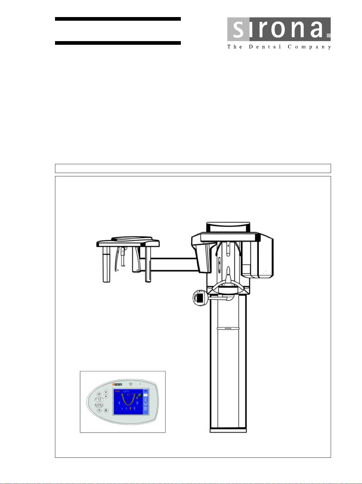
Unit description........................................................................................................ 18
3.1 Hardware...................................................................................................... 18
3.1.1 Information on the unit..................................................................... 18
3.1.2 System versions .............................................................................. 19
3.1.3 Sensor versions............................................................................... 20
3.1.4 Installation versions......................................................................... 21
3.1.5 Modules and components ............................................................... 22
3.1.5.1 Slide.................................................................................. 23
3.1.5.2 Stand ................................................................................ 24
3.1.5.3 Cephalometer................................................................... 25
3.1.5.4 Remote control ................................................................. 25
3.1.6 Cabling overview............................................................................. 26
3.1.7 Board photos ................................................................................... 32
3.1.7.1 Boards in the slide............................................................ 32
3.1.7.2 Boards in the stand........................................................... 39
3.1.7.3 Boards in the cephalometer (left- and right-arm versions)40
63 03 510 D3352
D3352.076.03.11.02 09.2016
3
Page 4

Table of contents Sirona Dental Systems GmbH
Service Manual ORTHOPHOS XG 3D / Ceph
3.1.7.4 Board in the remote control ............................................... 41
3.1.8 Covers.............................................................................................. 41
3.1.9 Technical Data ................................................................................. 44
3.2 Firmware ....................................................................................................... 49
4
General operating procedures.................................................................................. 60
4.1 Switching the unit on ..................................................................................... 60
4.1.1 Factory setting after switch-on ......................................................... 61
4.2 Updating the unit firmware ............................................................................ 62
4.2.1 Update mode.................................................................................... 67
4.2.2 Check program releases .................................................................. 69
4.3 Opening "Details" .......................................................................................... 71
4.4 Setup of an X-ray component ....................................................................... 73
4.4.1 Selecting an X-ray component ......................................................... 74
4.4.2 Approval of the X-ray component..................................................... 80
4.4.3 Deleting an X-ray component........................................................... 82
4.5 Using demo mode – operation without radiation release .............................. 83
4.5.1 Switching on demo mode................................................................. 83
4.5.2 Switching off demo mode................................................................. 84
4.5.3 Important information for repacking and transport ........................... 85
5
Messages ................................................................................................................. 88
5.1 Help messages ............................................................................................. 89
5.2 System messages ......................................................................................... 90
5.3 Status displays .............................................................................................. 90
5.4 Error messages ............................................................................................. 91
5.4.1 Error code: Ex yy zz ......................................................................... 91
5.4.2 Ex - Error type .................................................................................. 91
5.4.3 yy - Location..................................................................................... 93
5.4.4 General handling of error messages................................................ 93
5.5 List of error messages................................................................................... 94
5.5.1 Location 06: Tube assembly/DX6 .................................................... 94
5.5.2 Location 07: Easypad/DX7............................................................... 101
5.5.3 Location 10: System hardware......................................................... 105
5.5.4 Location 11: Power PC/Board DX11................................................ 108
5.5.5 Location 12: CAN bus ...................................................................... 111
5.5.6 Location 13: Stand/Peripherals ........................................................ 111
5.5.7 Location 14: Digital extension, SIDEXIS XG.................................... 125
5.5.8 Location 15: Configuration, update .................................................. 129
5.5.9 Location 42: Remote control ............................................................ 131
5.5.10 Location 61: Diaphragm control, board DX61 .................................. 135
5.5.11 Location 81, zz=1-23: Board DX81, pan slot.................................... 142
4 D3352.076.03.11.02 09.2016
63 03 510 D3352
Page 5

Sirona Dental Systems GmbH Table of contents
Service Manual ORTHOPHOS XG 3D / Ceph
5.5.12 Location 81, zz=51-78: Board DX81, ceph slot............................... 146
5.5.13 Location 88: Combisensor............................................................... 150
5.5.14 Location 91: Cephalometer, board DX91 ........................................ 155
6
Troubleshooting....................................................................................................... 160
6.1 Error logging memory................................................................................... 161
6.1.1 Example of error logging data ......................................................... 161
6.2 Checking the CAN bus ................................................................................. 163
6.2.1 Checking the CAN bus with the diagnostic function of board DX1.. 167
6.2.2 Jumper positions in the CAN bus .................................................... 168
6.3 Checking the boards .................................................................................... 169
6.3.1 Checking board DX32 ..................................................................... 171
6.4 Checking the motors .................................................................................... 173
6.5 Checking the light barriers............................................................................ 174
6.6 Device leakage current too high................................................................... 175
6.7 Checking the cables ..................................................................................... 176
bеЦдблЬ
6.8 Error analysis of X-RAY control signal path ................................................. 177
6.9 Checking the data paths............................................................................... 180
6.9.1 Creating 2D test images.................................................................. 180
6.9.2 Creating a 3D test image................................................................. 182
7
Adjusting and calibrating the unit............................................................................. 184
7.1 General information about unit adjustment and calibration .......................... 186
7.1.1 Displays and help messages during adjustment/calibration............ 187
7.1.2 "Adjustment/Calibration" menu........................................................ 188
7.1.2.1 Calling the "Adjustment/Calibration" menu....................... 188
7.1.2.2 Menu structure.................................................................. 189
7.1.3 Enabling exposure readiness .......................................................... 197
7.1.4 Taking an exposure......................................................................... 197
7.1.5 Save values..................................................................................... 197
7.1.6 Test phantoms for adjustment and calibration ................................ 198
7.1.6.1 OP XG needle phantom for panoramic adjustment.......... 198
7.1.6.2 OP XG 3D ceph adjustment phantom for the adjustment
of the cephalometer
7.1.6.3 Geometry phantom for volume calibration........................ 201
7.2 Adjustment and calibration via the "Unit adjustment/calibration" menu ....... 203
7.2.1 2D adjustment ................................................................................. 203
7.2.1.1 Pan sensor adjustment..................................................... 203
7.2.1.2 Pan diaphragm ................................................................. 206
7.2.1.3 Pan symmetry................................................................... 210
7.2.1.4 Ceph - Primary diaphragm ............................................... 214
7.2.1.5 Ceph - Fixed point of rotation ........................................... 218
200
63 03 510 D3352
D3352.076.03.11.02 09.2016
5
Page 6

Table of contents Sirona Dental Systems GmbH
Service Manual ORTHOPHOS XG 3D / Ceph
7.2.1.6 Ceph - Main X-ray beam direction..................................... 222
7.2.1.7 Ceph - Fixed point of rotation for QuickShot ..................... 225
7.2.1.8 Ear plug alignment ............................................................ 229
7.2.2 3D adjustment/calibration................................................................. 234
7.2.2.1 Sensor ............................................................................... 234
7.2.2.2 Aperture............................................................................. 235
7.2.2.3 Shading ............................................................................. 237
7.2.2.4 Shading (5x5) .................................................................... 238
7.2.2.5 Geometry........................................................................... 239
7.2.2.6 Dosimetry .......................................................................... 240
7.2.3 Saving adjustment/calibration data .................................................. 241
7.2.4 Resetting adjustment/calibration ...................................................... 242
7.3 Checking and adjusting the touchscreen ...................................................... 244
7.4 Mechanical adjustments................................................................................ 246
7.4.1 Mechanical adjustment: Ceph secondary diaphragm ...................... 246
8
Perform service routines via the control panel ......................................................... 248
8.1 Overview of service routines ......................................................................... 248
8.1.1 List of all service routines available for selection ............................. 248
8.1.2 Alphabetical list of service routine functions .................................... 251
8.2 Service menu and service routines ............................................................... 254
8.2.1 Displays and symbols in the service menu ...................................... 254
8.2.1.1 Easypad ............................................................................ 254
8.3 Basic operating procedures in the service menu .......................................... 256
8.3.1 Activating the service menu ............................................................. 256
8.3.1.1 Easypad ............................................................................ 256
8.3.2 Selecting service routines and test steps......................................... 258
8.3.2.1 Selecting a service routine ................................................ 258
8.3.2.2 Selecting a test step .......................................................... 258
8.3.2.3 Service routines with security access................................ 259
8.3.3 Select parameters ............................................................................ 261
8.3.4 Saving parameters ........................................................................... 262
8.3.5 Exiting the test step and service routine .......................................... 262
8.4 S001: Radiation without rotary movement, fixed maximum radiation time ... 263
8.5 S002: Radiation without rotary movement, selectable kV/mA level and
265
maximum radiation time
8.5.1 S002: Test step 1 ............................................................................. 265
8.5.2 S002: Test step 3 ............................................................................. 267
8.5.3 S002: Test step 4 ............................................................................. 269
8.5.4 S002: Test step 5 ............................................................................. 271
8.6 S005: General X-ray tube assembly service ................................................. 272
8.6.1 S005: Test step 1 ............................................................................. 272
6 D3352.076.03.11.02 09.2016
63 03 510 D3352
Page 7

Sirona Dental Systems GmbH Table of contents
Service Manual ORTHOPHOS XG 3D / Ceph
8.6.2 S005: Test step 2 ............................................................................ 274
8.6.3 S005: Test step 4 ............................................................................ 275
8.6.4 S005: Test step 5 ............................................................................ 276
8.6.5 S005: Test step 6 ............................................................................ 276
8.6.6 S005: Test step 7 ............................................................................ 278
8.7 S007: Error logging memory ........................................................................ 280
8.7.1 S007: Test step 1 ............................................................................ 280
8.7.2 S007: Test step 2 ............................................................................ 282
8.7.3 S007: Test step 5 ............................................................................ 283
8.7.3.1 Displaying the log with a web browser ............................. 284
8.8 S008: Update service ................................................................................... 286
8.8.1 S008: Test step 2 ............................................................................ 286
8.8.2 S008: Test step 3 ............................................................................ 287
8.9 S009: Flash file system ................................................................................ 288
8.9.1 S009: Test step 4 ............................................................................ 288
8.9.2 S009: Test step 5 ............................................................................ 289
8.9.3 S009: Test step 8 ............................................................................ 290
8.10 S011: Dosimetry (without ring movement) ................................................... 291
8.10.1 S011: Test step 14 .......................................................................... 291
8.10.2 S011: Test step 24 .......................................................................... 293
bеЦдблЬ
8.11 S012: CAN bus service ................................................................................ 294
8.11.1 S012: Test step 1 ............................................................................ 294
8.11.2 S012: Test step 2 ............................................................................ 296
8.11.3 S012: Test step 3 ............................................................................ 297
8.11.4 S012: Test step 4 ............................................................................ 298
8.12 S014: Rotation motor service ....................................................................... 299
8.12.1 S014: Test step 1 ............................................................................ 299
8.12.2 S014: Test step 2 ............................................................................ 300
8.12.3 S014: Test step 3 ............................................................................ 301
8.12.4 S014: Test step 4 ............................................................................ 301
8.13 S015: Actuator service ................................................................................. 302
8.13.1 S015: Test step 5 ............................................................................ 302
8.14 S017: Configuration service ......................................................................... 303
8.14.1 S017: Test step 2 ............................................................................ 304
8.14.2 S017: Test step 3 ............................................................................ 307
8.14.3 S017: Test step 4 ............................................................................ 308
8.14.4 S017: Test step 5 ............................................................................ 309
8.14.5 S017: Test step 6 ............................................................................ 311
8.14.6 S017: Test step 8 ............................................................................ 312
8.14.7 S017: Test step 12 .......................................................................... 313
8.14.8 S017: Test step 13 .......................................................................... 314
8.14.9 S017: Test step 14 .......................................................................... 315
63 03 510 D3352
D3352.076.03.11.02 09.2016
7
Page 8

Table of contents Sirona Dental Systems GmbH
Service Manual ORTHOPHOS XG 3D / Ceph
8.14.10 S017: Test step 15 ........................................................................... 317
8.14.11 S017: Test step 17 ........................................................................... 318
8.14.12 S017: Test step 18 (occlusal bite block only)................................... 321
8.14.13 S017: Test step 21 ........................................................................... 323
8.15 S018: Service for height adjustment ............................................................. 324
8.15.1 S018: Test step 2 ............................................................................. 325
8.15.2 S018: Test step 3 ............................................................................. 326
8.15.3 S018: Test step 4 ............................................................................. 327
8.15.4 S018: Test step 5 ............................................................................. 328
8.15.5 S018: Test step 6 ............................................................................. 329
8.15.6 S018: Test step 7 (occlusal bite block only)..................................... 330
8.15.7 S018: Test step 8 (occlusal bite block only)..................................... 332
8.15.7.1 Codes of possible error modes ......................................... 333
8.15.8 S018: Test step 9 (occlusal bite block only)..................................... 334
8.15.9 S018: Test step 10 (occlusal bite block only)................................... 336
8.16 S020: Service for temple support.................................................................. 337
8.16.1 S020: Test step 1 ............................................................................. 337
8.17 S021: Service for motor-driven diaphragm ................................................... 339
8.17.1 S021: Test step 1 ............................................................................. 339
8.18 S032: Sensor test.......................................................................................... 341
8.18.1 S032: Test step 10 ........................................................................... 341
8.18.1.1 S032: Test step 10: Explanations on the test procedure... 343
8.18.1.2 S032: Test step 10: Result of synchronized readout
343
sequence
8.18.2 S032: Test step 50 ........................................................................... 344
8.18.2.1 Possible results of self-test and troubleshooting measures 344
8.18.3 S032: Test step 56 ........................................................................... 345
8.19 S033: Test of ceph image path without SIDEXIS XG (for ceph units only)... 346
8.19.1 S033: Test step 10 ........................................................................... 346
8.20 S034: Service for the digital cephalometer ................................................... 348
8.20.1 S034: Test step 4 ............................................................................. 348
8.20.2 S034: Test step 5 ............................................................................. 352
8.20.3 S034: Test step 6 ............................................................................. 355
8.20.4 S034: Test step 8 ............................................................................. 356
8.20.5 S034: Test step 9 ............................................................................. 358
8.21 S037: Network service .................................................................................. 360
8.21.1 S037: Test step 1 ............................................................................. 360
8.21.2 S037: Test step 2 ............................................................................. 362
8.21.3 S037: Test step 3 ............................................................................. 364
8.21.4 S037: Test step 4 ............................................................................. 365
9
Repair....................................................................................................................... 368
63 03 510 D3352
8 D3352.076.03.11.02 09.2016
Page 9

Sirona Dental Systems GmbH Table of contents
Service Manual ORTHOPHOS XG 3D / Ceph
9.1 Safety checks ............................................................................................... 369
9.2 Height adjustment motor (M1_4)/spindle...................................................... 370
9.2.1 Preparing for motor replacement..................................................... 370
9.2.1.1 Moving the slide manually ................................................ 370
9.2.2 Removing board DX32 .................................................................... 374
9.2.3 Replacing the height adjustment motor/spindle .............................. 376
9.2.4 Laying of cables when replacing the height adjustment motor........ 378
9.2.5 What has to be done after replacing the height adjustment motor
380
(M1_4) or the spindle?
9.3 Ring motor (M1_3)........................................................................................ 381
9.3.1 Replacing the ring motor ................................................................. 381
9.3.2 Replacing the pinion at the ring motor............................................. 382
9.3.3 Laying of cables when replacing the ring motor.............................. 383
9.3.4 What has to be done after replacing the ring motor (M1_3)/pinion? 383
9.4 Pan actuators (M1_1/2) ................................................................................ 384
9.4.1 Replacing actuators......................................................................... 384
9.4.2 Laying of cables when replacing the actuator ................................. 385
9.4.3 What has to be done after replacing the actuators?........................ 385
bеЦдблЬ
9.5 Head support................................................................................................ 386
9.5.1 Replacing the headrest ................................................................... 386
9.5.2 Laying of cables when replacing the headrest ................................ 387
9.5.3 What has to be done after replacing the headrest? ........................ 387
9.6 Control panel ................................................................................................ 388
9.6.1 Replacing the user interface............................................................ 388
9.6.1.1 What has to be done after replacing the user interface?..389
9.6.2 Replacing the control panel............................................................. 390
9.6.2.1 What has to be done after replacing the control panel?...391
9.6.3 Laying cables for control panel replacement................................... 391
9.7 Laser light localizers..................................................................................... 392
9.7.1 FH double laser light localizer (pan)................................................ 392
9.7.1.1 Replacing the laser module in the FH double laser light
392
localizer (pan)
9.7.1.2 Adjusting the FH double laser light localizer (PAN).......... 393
9.7.2 FH laser light localizer (Ceph)......................................................... 395
9.7.2.1 Replacing the ceph laser module in the FH laser light
395
localizer (ceph)
9.7.2.2 Adjusting the FH laser light localizer (Ceph) .................... 396
9.7.3 MS laser light localizer (pan) ........................................................... 398
9.7.3.1 Replacing the laser module in the MS laser light localizer
398
(pan)
9.7.3.2 Adjusting the MS laser light localizer (PAN)..................... 399
9.8 Occlusal bite block ....................................................................................... 401
63 03 510 D3352
D3352.076.03.11.02 09.2016
9
Page 10

Table of contents Sirona Dental Systems GmbH
Service Manual ORTHOPHOS XG 3D / Ceph
9.8.1 Replacing the occlusal bite block ..................................................... 401
9.8.2 What has to be done after replacing the occlusal bite block?.......... 401
9.9 Bite block holder............................................................................................ 402
9.9.1 Replacing the bite block holder ........................................................ 402
9.9.2 Replacing the silicone rings ............................................................. 403
9.9.3 What has to be done after replacing the bite block holder/silicone
403
ring?
9.10 Diaphragm unit.............................................................................................. 404
9.10.1 Replacing the diaphragm unit .......................................................... 404
9.10.2 What has to be done after replacing the diaphragm unit? ............... 405
9.11 X-ray tube unit............................................................................................... 406
9.11.1 Replacing the X-ray tube assembly ................................................. 406
9.11.2 Cables and connectors for replacement of the X-ray tube assembly 408
9.11.3 What has to be done after replacing the X-ray tube assembly? ...... 410
9.12 Fan (X-ray tube assembly)............................................................................ 412
9.12.1 Replacing the fan (tube assembly 1.0)............................................. 412
9.12.2 Replacing the fan (tube assembly 2.0)............................................. 413
9.12.3 What has to be done after replacing the fan? .................................. 414
9.13 Combisensor ................................................................................................. 415
9.13.1 Replacing the rotation unit ............................................................... 415
9.13.2 Replacing the 3D module................................................................. 417
9.13.2.1 What has to be done after replacing the 3D module?....... 420
9.13.3 Replacing the 2D sensor (Pan) ........................................................ 421
9.13.3.1 What has to be done after replacing the 2D sensor (Pan)? 423
9.14 Cephalometer................................................................................................ 424
9.14.1 Replacing the ceph sensor holder.................................................... 424
9.14.1.1 What has to be done after replacing the ceph sensor
424
holder?
9.14.2 Replacing the ceph sensor............................................................... 425
9.14.2.1 What has to be done after replacing the ceph sensor?..... 425
9.15 Light barriers ................................................................................................. 426
9.15.1 Replacing the light barriers .............................................................. 426
9.15.2 What has to be done after replacing the light barriers? ................... 427
9.16 Boards........................................................................................................... 428
9.16.1 Important notes about replacing boards........................................... 428
9.16.2 Replacing boards ............................................................................. 429
9.16.2.1 Replacing PC board DX1 .................................................. 430
9.16.2.2 Replacing board DX11 ...................................................... 431
9.16.2.3 Replacing board DX32 ...................................................... 431
9.16.3 Measures following replacement of boards...................................... 432
9.16.3.1 After changing the DX11 board ......................................... 435
9.17 Cable............................................................................................................. 437
10 D3352.076.03.11.02 09.2016
63 03 510 D3352
Page 11

Sirona Dental Systems GmbH Table of contents
Service Manual ORTHOPHOS XG 3D / Ceph
9.17.1 Replacing energy chain 1 completely.............................................. 437
9.17.2 Replacing cables ............................................................................. 441
9.17.2.1 Replacing fiber-optic cable L5, L6 or L15......................... 441
9.17.2.2 Cable exchange (L3, L5, L6, L11, L12, and L15)/Laying
the cable/corrugated tube at the rotation unit
9.17.2.3 Replacing cable L117 or L108 in cable track 2................. 444
9.17.2.4 Replacing cable L1 or grounding strap in cable track 1.... 446
442
10
Maintenance............................................................................................................ 447
10.1 Calibrating the unit ....................................................................................... 447
10.2 Checking the height adjustment ................................................................... 448
10.3 Checking the forehead and temple supports................................................ 449
10.4 Checking the rotation unit of the combisensor for smooth and easy running 450
10.5 Testing the rotating unit for smooth running................................................. 450
10.6 Inspecting the bite block holder.................................................................... 451
10.7 Checking the ceph sensor holder................................................................. 452
10.8 Checking the laser light localizers................................................................ 453
10.9 Checking the X-ray images .......................................................................... 457
10.10 Checking the tube data ................................................................................ 458
10.10.1 Checking the tube voltage............................................................... 458
10.10.1.1Checking the tube voltage characteristic during exposure
(tube assembly 1.0)
10.10.1.2Testing the tube voltage (tube assembly 2.0) .................. 463
10.10.2 Checking the tube current ............................................................... 464
10.10.3 Checking the radiation time............................................................. 467
10.10.4 Checking the fan and temperature sensor ...................................... 468
458
bеЦдблЬ
10.11 Test exposures/Test images ........................................................................ 469
10.11.1 2D test exposures ........................................................................... 470
10.11.2 3D test exposures ........................................................................... 480
10.12 Checking the cables for damage.................................................................. 490
10.13 Checking the idling rollers ............................................................................ 491
63 03 510 D3352
D3352.076.03.11.02 09.2016
10.11.1.1Panoramic diaphragm test exposure (2D)........................ 470
10.11.1.2Pan - Symmetry test exposure (2D)................................. 472
10.11.1.3Ceph - Fixed point of rotation test exposure (2D) ............ 475
10.11.1.4Quality test exposure (2D)................................................ 477
10.11.1.52D test pattern.................................................................. 478
10.11.2.1Diaphragm test exposure (3D) ......................................... 480
10.11.2.2Quality test exposure (3D)................................................ 484
10.11.2.3Sensor test image (3D) .................................................... 485
10.11.2.4Dosimetry (3D) ................................................................. 487
10.11.2.5Dark current exposure (3D).............................................. 488
11
Page 12

Table of contents Sirona Dental Systems GmbH
Service Manual ORTHOPHOS XG 3D / Ceph
10.14 Checking the grounding straps ..................................................................... 492
10.15 Checking the cable shields ........................................................................... 493
10.16 Checking the protective ground wires ........................................................... 494
10.17 Checking the device leakage current ............................................................ 499
11
12
Dismantling and disposal ......................................................................................... 500
11.1 Dismantling and reinstallation ....................................................................... 500
11.2 Disposal ........................................................................................................ 500
Service Manual History ............................................................................................ 502
12 D3352.076.03.11.02 09.2016
63 03 510 D3352
Page 13

Sirona Dental Systems GmbH 1About this Service Manual
Service Manual ORTHOPHOS XG 3D / Ceph 1.1Scope
About this Service Manual
1
1.1
1.2
1.3
Scope
Scope of the Service Manu al: XG 3D
This Service Manual describes the servicing of the ORTHOPHOS XG 3D/
Ceph digital volume tomograph. It is intended for use exclusively by
trained and authorized distributors and service technicians.
Other documentation required
In addition to this manual, you need the following documents:
Spare parts list
● GALILEOS List of Spare Parts: Order No. 61 25 699
Wiring diagrams
● GALILEOS Wiring References: Order No. 61 25 640
DVD text
Current Service Documentation, such as the Service Manual, can be
downloaded from the Sirona dealer website.
Tools and auxiliary materials
Tools and auxiliary materials: XG
● Screwdriver set (slot and Phillips)
● Torx offset screwdrivers TX10, TX20, TX25
(included in the scope of supply)
bеЦдблЬ
● Open-end wrench, 13 mm A/F
● Socket wrench, 13 mm A/F
● Side cutting pliers
● Spirit level
● Digital Multimeter, Accuracy Class 1
● Mult-O-Meter 512L
● Soldering tool for repairing cables
● Cable ties
● Teflon tape
● Loctite
63 03 510 D3352
D3352.076.03.11.02 09.2016
13
Page 14
1About this Service Manual Sirona Dental Systems GmbH
1.4Structure of the document Service Manual ORTHOPHOS XG 3D / Ceph
1.4
Structure of the document
1.4.1 Identification of the danger levels
To prevent personal injury and material damage, please observe the
warning and safety information provided in these operating instructions.
Such information is highlighted as follows:
DANGER
An imminent danger that could result in serious bodily injury or death.
WARNING
A possibly dangerous situation that could result in serious bodily injury
or death.
CAUTION
A possibly dangerous situation that could result in slight bodily injury.
NOTICE
A possibly harmful situation which could lead to damage of the product
or an object in its environment.
IMPORTANT
Application instructions and other important information.
Tip: Information on making work easier.
1.4.2 Formats and symbols used
The formats and symbols used in this document have the following
meaning:
Prerequisite
1. First action step
2. Second action step
or
➢ Alternative action
Result
➢ Individual action step
See "Formats and symbols
used [ → 14]"
● List Designates a list.
"Command / menu item" Indicates commands, menu items or
Prompts you to do something.
Identifies a reference to another text
passage and specifies its page
number.
quotations.
14 D3352.076.03.11.02 09.2016
63 03 510 D3352
Page 15
Sirona Dental Systems GmbH 2Safety instructions
Service Manual ORTHOPHOS XG 3D / Ceph 2.1Modifications to the unit
Safety instructions
2
2.1
2.2
2.3
Modifications to the unit
Modifications to this unit which might affect the safety of the system
owner, patients or other persons are prohibited by law!
For reasons of product safety, this product may be operated only with
original Sirona accessories or third-party accessories expressly approved
by Sirona. The user is responsible for any damage resulting from the use
of non-approved accessories.
Fixed connection
DANGER
Potentially lethal shock hazard!
Fixed connection!
Installing a mains plug instead of the specified fixed connection infringes
international medical regulatory actions and is prohibited. In case of
error, this puts patients, users, and other parties seriously at risk.
Electromagnetic compatibility
The unit complies with the requirements of standard IEC 60601-1-2.
Medical electrical equipment is subject to special EMC-related
precautions. It must be installed and operated as specified in the
document "Installation Requirements".
bеЦдблЬ
2.4
2.5
If high-voltage systems, radio link systems or MRI systems are located
within 5 m of the unit, please observe the specifications stated in the
installation requirements.
Portable and mobile RF communications equipment may affect medical
electrical equipment. Therefore, the use of mobile wireless phones in
medical office or hospital environments must be prohibited.
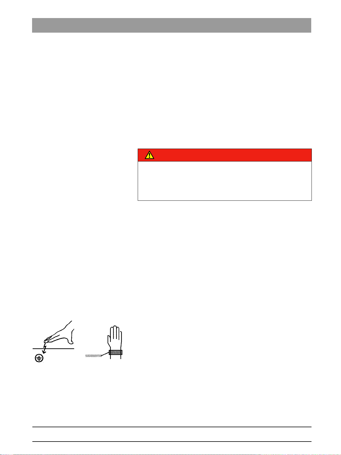
Electrostatic discharge
Electrostatic discharge (abbreviated: ESD – ElectroStatic Discharge)
Electrostatic discharge from people can damage electronic components
when the components are touched.
Touch a ground point to discharge static electricity before touching any
boards.
Switching the unit on
Safety information for switching on the unit: Service engineer
XGPF-63464; Patient position when switching on
Due to the risk of injury caused by malfunction, no person may be
positioned in the unit when it is switched on.
63 03 510 D3352
D3352.076.03.11.02 09.2016
15
Page 16
2Safety instructions Sirona Dental Systems GmbH
2.6Condensation Service Manual ORTHOPHOS XG 3D / Ceph
2.6
2.7
2.8
Condensation
Safety information for condensation: Service engineer
Extreme fluctuations of temperature may cause condensation inside the
unit. Do not switch the unit on before it has reached normal room
temperature. See also the chapter "Technical details"
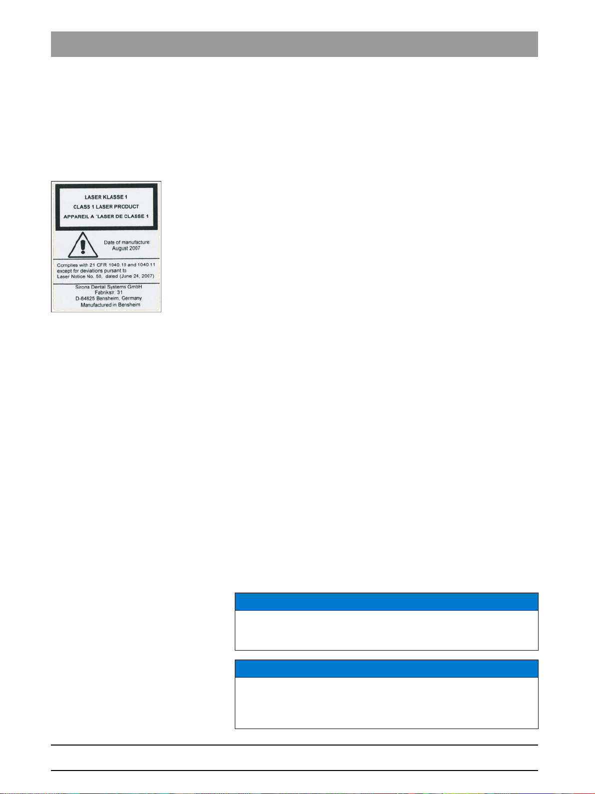
Laser light localizer
Safety information for light loca lizer: Service engineer
The system incorporates Class 1 laser products.
A minimum distance of 10 cm (4") is required between the eye and the
laser. Do not stare into the beam.
Do not use the system with any other lasers, and do not make any
changes to settings or processes that are not described in these
operating instructions. This may lead to a dangerous exposure to
radiation.
Ventilation slots
Ventilation slots
Never cover the ventilation slots on the unit under any circumstances,
since this may obstruct air circulation. This can cause the unit to overheat.
2.9
2.10
Qualifications of service personnel
Installation and startup may be carried out only by personnel specifically
authorized by Sirona.
Radiation protection
Safety information for radiation protection: Service engineer
The valid radiation protection regulations and measures must be
observed. The statutory radiation protection equipment must be used.
During an exposure, the service engineer should move as far away from
the X-ray tube assembly as the coiled cable of the manual release
permits.
With the exception of the service engineer, no other persons are allowed
to stay in the room during an exposure.
In case of malfunctions, cancel the exposure immediately by letting go of
the exposure release button.
Information about radiation protection for Canada
NOTICE
3D imaging should not be used for screening examinations. 3D imaging
examinations must be clinically warranted and each exam must be
justified by demonstrating that the benefits outweigh the risks.
NOTICE
Where it is likely that evaluation of soft tissues will be required as part of
the patient's radiological assessment, the appropriate imaging should
be conventional medical CT or MR, rather than 3D imaging using Cone
Beam technology.
16 D3352.076.03.11.02 09.2016
63 03 510 D3352
Page 17
Sirona Dental Systems GmbH 2Safety instructions
Service Manual ORTHOPHOS XG 3D / Ceph 2.11Safety checks
2.11
2.12
Safety checks
Safety checks
Once repairs are completed, the circuit breaker test and unit leakage
current test must be carried out (see chapter "Checking the circuit
breaker" and "Checking the unit leakage current").
Functional check
Note for XG 3D:
CAUTION
Be sure to observe the descriptions and safety information given in the
chapter titled "Switching the unit on [ → 60]" and "Test exposures/Test
images [ → 469]".
Following any form of service and maintenance work, a functional check
must be performed on the device.
Perform the following test steps:
1. Perform a restart of the unit:
–Switch the unit off.
– Wait 1 minute.
–Switch the unit on.
– Wait for the self-test.
2. Perform a 2D test exposure using the needle phantom included in the
scope of supply.
3. Perform a 3D test exposure using the constancy test phantom / DIN
DVT test phantom included in the scope of supply.
bеЦдблЬ
63 03 510 D3352
D3352.076.03.11.02 09.2016
17
Page 18
3Unit description Sirona Dental Systems GmbH
3.1Hardware Service Manual ORTHOPHOS XG 3D / Ceph
Unit description
3
Accompanying documents
Electrostatic discharge (ESD)
Identification of single use devices
3.1
Hardware
3.1.1 Information on the unit
The following symbols are applied to the unit:
Accompanying documents
This symbol is affixed next to the unit rating plate.
Meaning: When operating the unit, observe the operating instructions.
This symbol is affixed on the unit rating plate.
Meaning: The accompanying documents are available on the homepage
of Sirona.
Connector pins or sockets bearing ESD warning labels must not be
touched or interconnected without ESD protective measures. See also
"Electrostatic Discharge" and "Electromagnetic Compatibility" [ → 15].
XGPF-36245; Single use hygienic protective sleev es
Prior to each exposure, the hygienic protective sleeves (single use
devices) must be fitted.
Single use devices are identified with the symbol shown on the left. They
must be disposed of immediately after use. Do not use single use devices
more than once.
18 D3352.076.03.11.02 09.2016
63 03 510 D3352
Page 19
Sirona Dental Systems GmbH 3Unit description
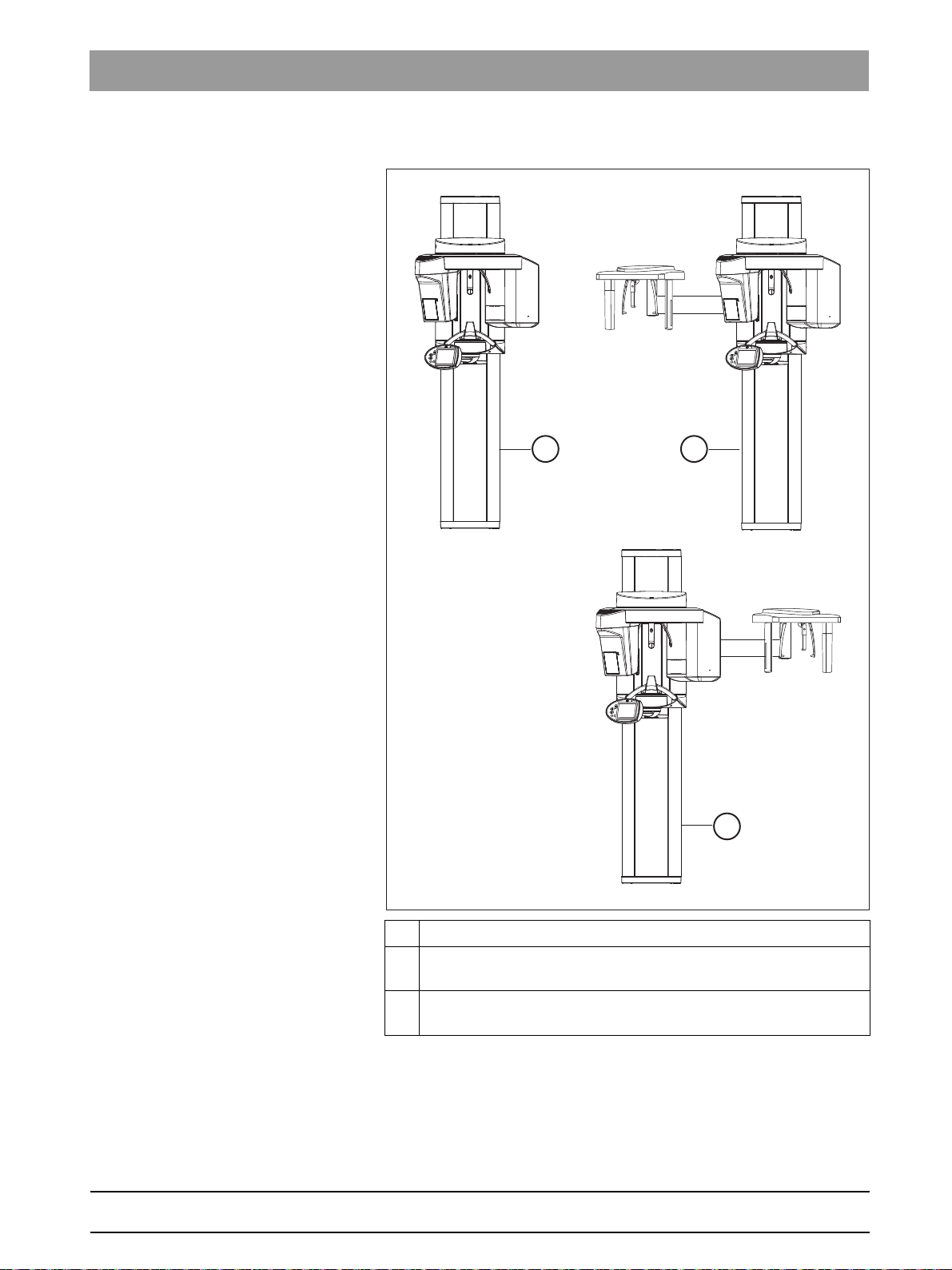
A
B
C
Service Manual ORTHOPHOS XG 3D / Ceph 3.1Hardware
3.1.2 System versions
XG3D device version
bеЦдблЬ
A ORTHOPHOS XG 3D, digital volume tomograph
B ORTHOPHOS XG 3D/Ceph,
digital volume tomograph with cephalometer, left-arm version
C ORTHOPHOS XG 3D/Ceph,
digital volume tomograph with cephalometer, right-arm version
63 03 510 D3352
D3352.076.03.11.02 09.2016
19
Page 20
3Unit description Sirona Dental Systems GmbH
3.1Hardware Service Manual ORTHOPHOS XG 3D / Ceph
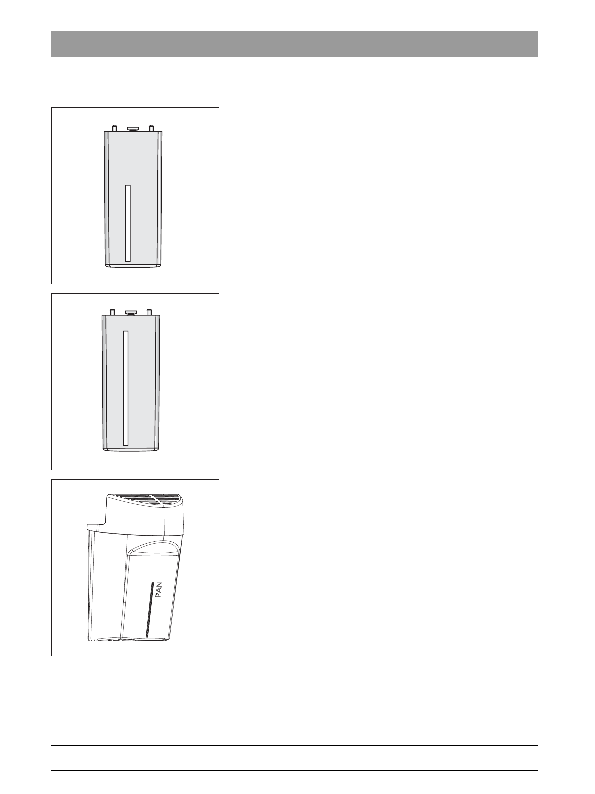
3.1.3 Sensor versions
Sensor XG PAN: Sensor for panoramic X-ray (PAN)
Sensor XG CEPH: Sensor for panoramic and cephalometric
(CEPH) X-ray
PAN/3D combisensor:
Sensor for panoramic X-ray (PAN) and volume exposures (3D)
63 03 510 D3352
20 D3352.076.03.11.02 09.2016
Page 21
Sirona Dental Systems GmbH 3Unit description
C
B
A
Service Manual ORTHOPHOS XG 3D / Ceph 3.1Hardware
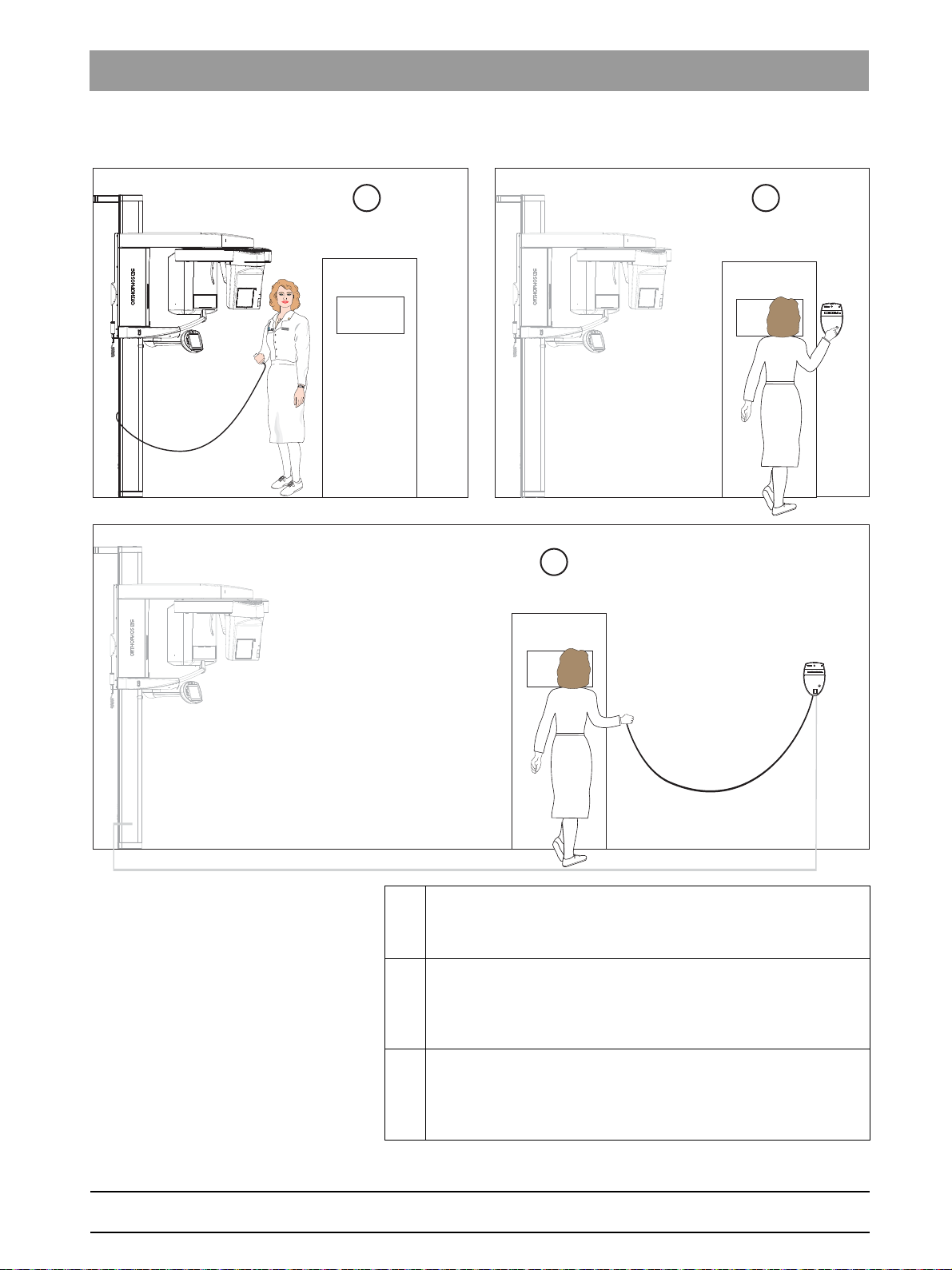
3.1.4 Installation versions
Installation versions: XG 3D
A Standard installation
Unit
without remote control with release button on the coiled cable
in the treatment room.
B Installation version 1
with remote control
Unit
outside the X-ray room
button on the coiled cable.
without release button and coiled cable).
C Installation version 2
bеЦдблЬ
without release
(see section Installation version 1:
63 03 510 D3352
D3352.076.03.11.02 09.2016
Unit
with remote control
button on the coiled cable.
release button and coiled cable).
outside the X-ray room
(see section Installation version 2: with
with release
21
Page 22
3Unit description Sirona Dental Systems GmbH
D
A
B
C
3.1Hardware Service Manual ORTHOPHOS XG 3D / Ceph
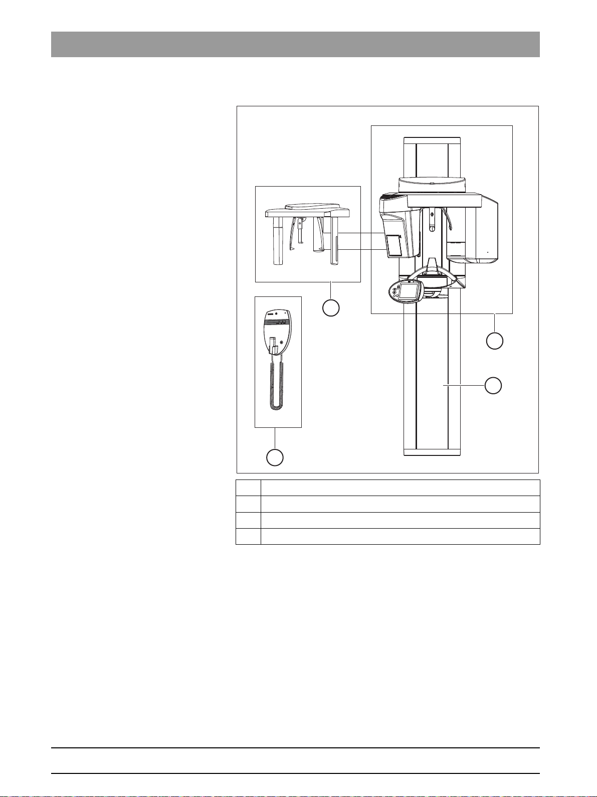
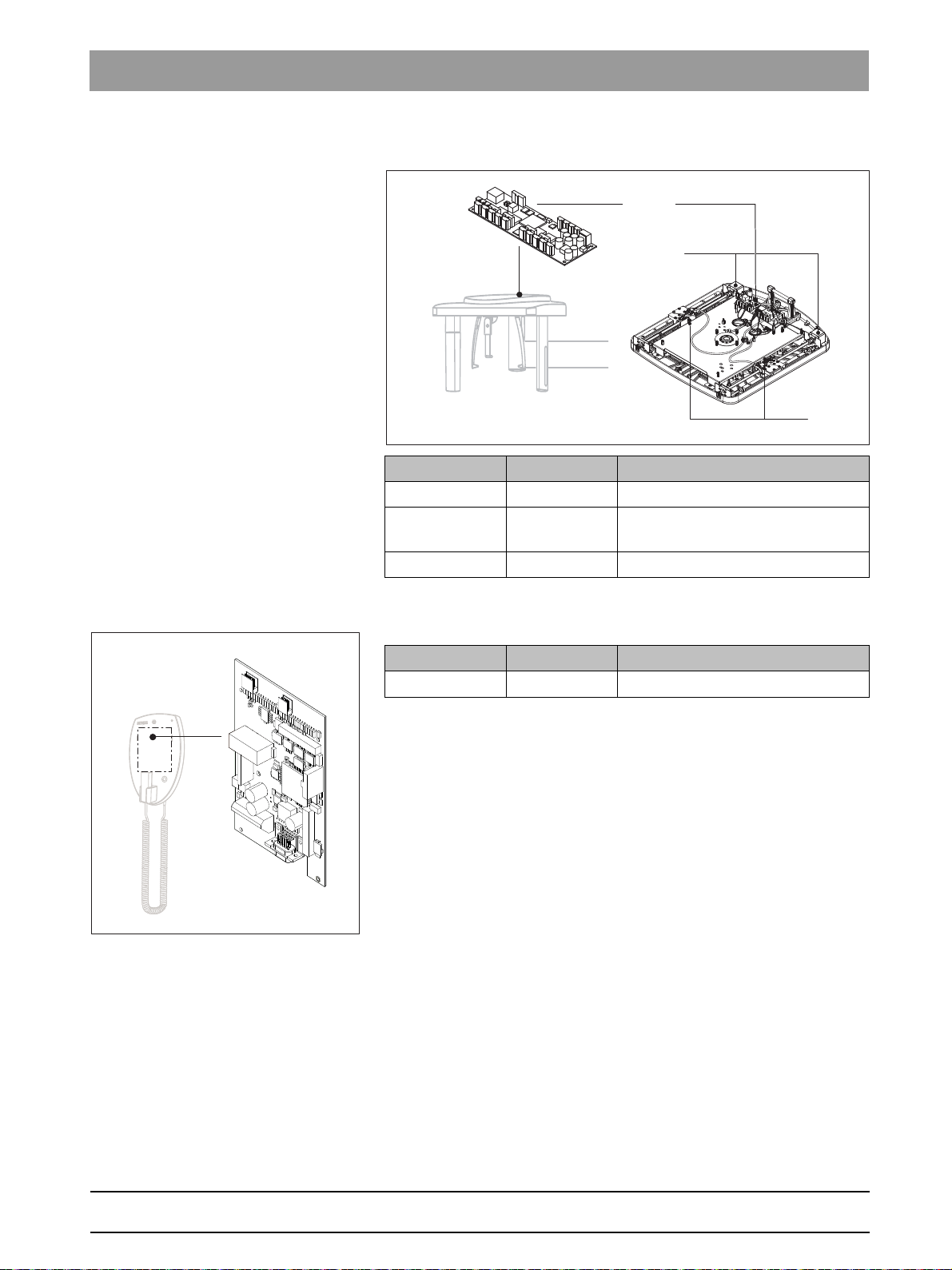
3.1.5 Modules and components
Modules and components: XG 3D
A Slide [ → 23]
B Stand [ → 24]
C Cephalometer [ → 25]
D Remote control [ → 25]
22 D3352.076.03.11.02 09.2016
63 03 510 D3352
Page 23
Sirona Dental Systems GmbH 3Unit description
DX11
DX1 M1*, M2*DX5*
LS*
DX6*
DX61*
DX51
DX7*
DX81P*, DX85P*
DX88
M
U
LS
LS
M, M
AK1 AK2
B
A
Service Manual ORTHOPHOS XG 3D / Ceph 3.1Hardware
3.1.5.1
Slide
Slide: XG 3D
bеЦдблЬ
63 03 510 D3352
D3352.076.03.11.02 09.2016
Component Designation Function
Boards DX1 Open loop/closed loop control in
DX11 Controller board
DX5* Headrest adapter
DX51* Occlusal bite block
DX6* (A) Open-loop/closed-loop control
DX6* (B) Open-loop/closed-loop control
DX7* Easypad touchscreen
DX61* Diaphragm control
DX81P Digital sensor
DX85P* Digital sensor power supply
DX88 Image memory
general
(tube assembly 1.0)
(tube assembly 2.0)
23
Page 24
3Unit description Sirona Dental Systems GmbH
DX32
MHV
3.1Hardware Service Manual ORTHOPHOS XG 3D / Ceph
Component Designation Function
Motor MU Rotary movement of rotating
element
MAK1, MAK2 Linear movement of rotating
element
M1*, M2* Linear movement of headrest
Light barriers LS Position control of the ring cycle
*) not available as individual repair part (see spare parts list).
3.1.5.2
Stand
Stand: XG 3D
Component Designation Function
Boards DX32 Power supply board
Motor MHV Linear movement of height
adjustment
63 03 510 D3352
24 D3352.076.03.11.02 09.2016
Page 25
Sirona Dental Systems GmbH 3Unit description
LS
MS
DX91
DX42
Service Manual ORTHOPHOS XG 3D / Ceph 3.1Hardware
3.1.5.3
3.1.5.4
Cephalometer
Component Designation Function
Boards DX91 Cephalometer control
Motors MS Stepping motors: linear movement
of secondary diaphragm and sensor
Light barriers LS Position check
Remote control
bеЦдблЬ
Component Designation Function
Board DX42 Display board for remote control
63 03 510 D3352
D3352.076.03.11.02 09.2016
25
Page 26
3Unit description Sirona Dental Systems GmbH
DX32 / X2
DX6 / X3
DX32 / X1
DX1 / X100
DX1 / J302
DX6 / J6
C
B
A
L1
L4
DX1
L5
DX6
DX32
L3
L2
L1
L2
L3
L4
L5
3.1Hardware Service Manual ORTHOPHOS XG 3D / Ceph
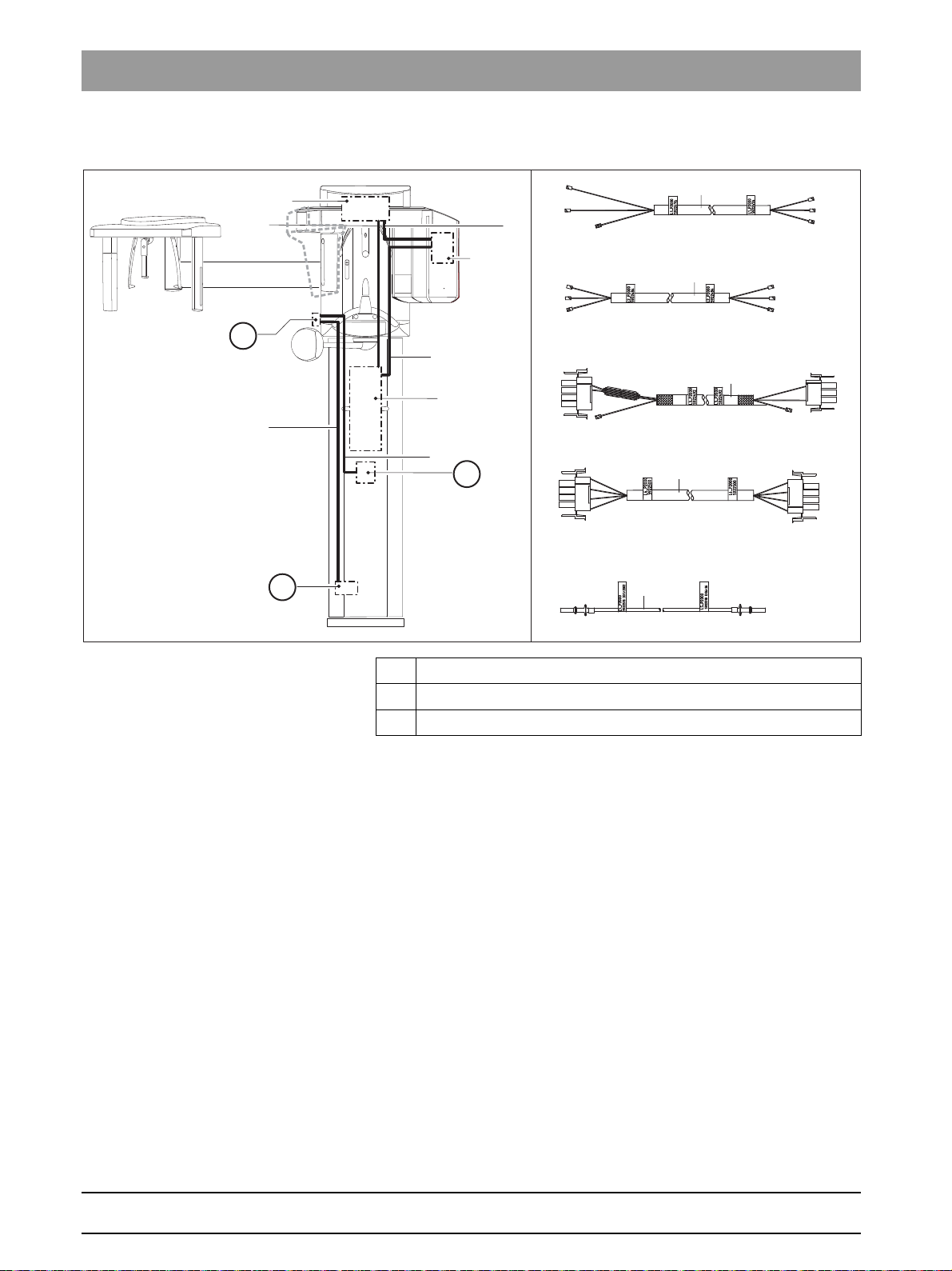
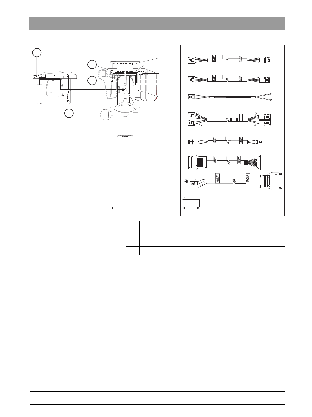
3.1.6 Cabling overview
Cabling overview: XG 3D
A Power switch/S1
B Line filter
C Wago terminal
26 D3352.076.03.11.02 09.2016
63 03 510 D3352
Page 27
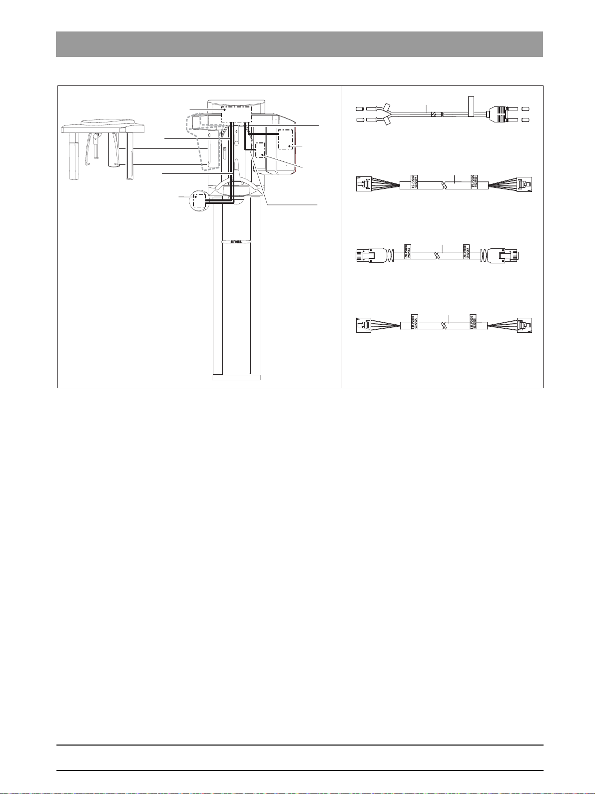
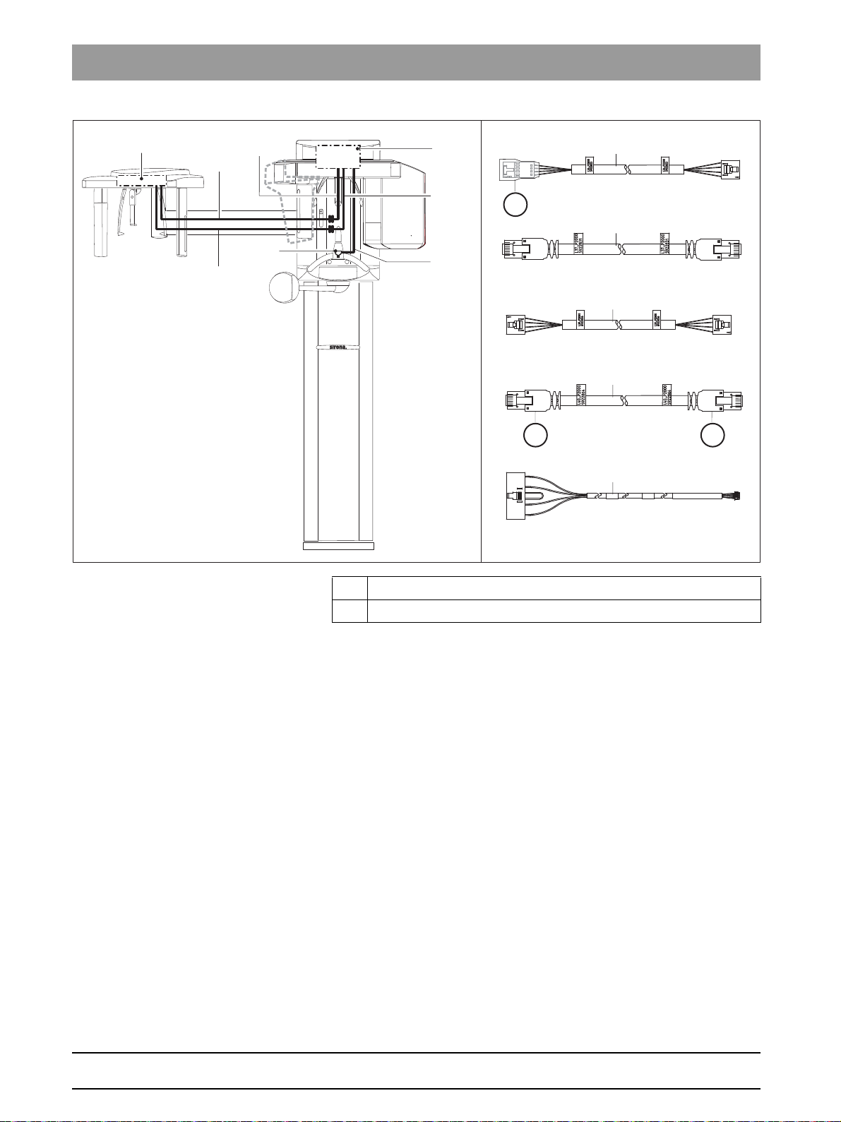
Sirona Dental Systems GmbH 3Unit description
DX1 / X104
DX7 / X102
DX1 / X302
DX7 / X103
DX1 / X102
DX61 / X501
DX1 / J306 – J307
DX6 / J2 – J3
L6_
X
G
592252
6
L
6
5
9
2
2
5
2
6
D
X
1
/
J
3
0
7
L
6
5
9
2
2
5
2
6
D
X
1
/
J
3
0
6
DX7
L9
L10
DX1
L6
DX6
DX61
L11
L6
L9
L10
L11
Service Manual ORTHOPHOS XG 3D / Ceph 3.1Hardware
bеЦдблЬ
63 03 510 D3352
D3352.076.03.11.02 09.2016
27
Page 28
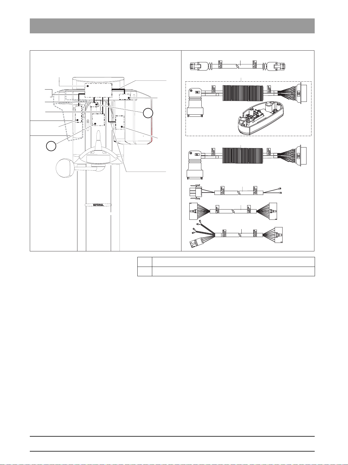
3Unit description Sirona Dental Systems GmbH
DX1 / X306
DX61 / X101
DX1 / X500
DX81 / X100
DX1 / X404
DX5 / X1
DX1 / X610
DX1 / X403
DX1 / X500
DX81 / X100
B
A
DX81
L16
L19
L13.1
L13
DX1
L18
DX5
DX61
L12
L12
L13
L13.1
L16
L18
L19
3.1Hardware Service Manual ORTHOPHOS XG 3D / Ceph
AHA motor
B LS sensor
63 03 510 D3352
28 D3352.076.03.11.02 09.2016
Page 29
Sirona Dental Systems GmbH 3Unit description
DX61 / X91
DX5
DX81 / X100
DX1 / X503
DX61 / X203
TSA Motor
LASER
LS
AMP
LS
L24_XG
6090760
L24_XG
6090760
DX91/
X407
DX91/
X302
AMP
DX91/X302
DX91/X407
D
C
B
A
L21
DX91
DX1
DX6
L23
L24
L20
DX61
L38
L35
DX81
L21
L20
L21
L23
L24
L31
L35
L38
L31
Service Manual ORTHOPHOS XG 3D / Ceph 3.1Hardware
A Potentiometer
B Motor
C Laser module
D LS sensor
bеЦдблЬ
63 03 510 D3352
D3352.076.03.11.02 09.2016
29
Page 30
3Unit description Sirona Dental Systems GmbH
DX91 / X6
DX91 / X101
DX1 / X103
DX1 / X309
DX1 / X1000
DX51 / X1
L41
B
A
DX91
DX1
DX51
L36
L39
L37
L40
L41
L36
L37
L39
B
L40
L41
3.1Hardware Service Manual ORTHOPHOS XG 3D / Ceph
A Heat shrink tube
B Cover, blue
63 03 510 D3352
30 D3352.076.03.11.02 09.2016
Page 31

Sirona Dental Systems GmbH 3Unit description
L108_XG
6094705
DX1/
X303
L117/
X103
L108_XG
6094705
DX1 / X303
L117 / X103
L117_XG
6094697
L117_XG
6094697
DX42 / X100
L108 / X103
DX1 / J901
A
DX1
DX42
L108
L7
L117
L25
L26
L7
L25
L26
L108
L117
A
DX88 / X209
DX88 / X210
L15 XG
6319185 DX1/J309
L15 XG
6319185 DX6/J5
Hersteller-
produktionsdaten
DX1 / J309 DX6 / J5
DX81 / X100
(Ltg.1)
(Ltg.2)
DX88/X212
DX88/X211
Kabel L80
AEM:
6279116 D3559
<KW/JAHR>
DX81/X100
DX88 / X211
DX88 / X212
DX1 / X111
A
L80 L13 L14
DX1
L15
DX6
DX88
DX81
L13
L14
L15
L80
Service Manual ORTHOPHOS XG 3D / Ceph 3.1Hardware
A Media converter
bеЦдблЬ
63 03 510 D3352
D3352.076.03.11.02 09.2016
31
Page 32

3Unit description Sirona Dental Systems GmbH
3.1Hardware Service Manual ORTHOPHOS XG 3D / Ceph
3.1.7 Board photos
3.1.7.1
Boards DX1/DX11 Installed up to unit serial number 628999 for "ORTHPHOS XG3D" and
Boards in the slide
XG 3D DX1/DX11 old version
648999 for "ORTHPHOS XG3D/Ceph"
XG 3D DX1/DX11 new version, ca. October 2011
63 03 510 D3352
32 D3352.076.03.11.02 09.2016
Page 33

Sirona Dental Systems GmbH 3Unit description
Service Manual ORTHOPHOS XG 3D / Ceph 3.1Hardware
Boards DX1/DX11 Installed as of unit serial number 629000 for "ORTHPHOS XG3D" and
649000 for "ORTHPHOS XG3D/Ceph"
IMPORTANT
The DX1/DX11V2 board can only be operated with unit software version
V04.04.00 or higher.
bеЦдблЬ
63 03 510 D3352
D3352.076.03.11.02 09.2016
33
Page 34

3Unit description Sirona Dental Systems GmbH
3.1Hardware Service Manual ORTHOPHOS XG 3D / Ceph
Board DX51
DX51: XG 3D
DX6: XG3D
34 D3352.076.03.11.02 09.2016
63 03 510 D3352
Page 35

Sirona Dental Systems GmbH 3Unit description
Service Manual ORTHOPHOS XG 3D / Ceph 3.1Hardware
Board DX6 This board is not available as a spare part or a repair part. X-ray tube
assemblies can only be ordered as complete units.
DX6 in X-ray tube assembly 1.0:
bеЦдблЬ
63 03 510 D3352
D3352.076.03.11.02 09.2016
35
Page 36

3Unit description Sirona Dental Systems GmbH
3.1Hardware Service Manual ORTHOPHOS XG 3D / Ceph
DX6 in X-ray tube assembly 2.0:
36 D3352.076.03.11.02 09.2016
63 03 510 D3352
Page 37

Sirona Dental Systems GmbH 3Unit description
Service Manual ORTHOPHOS XG 3D / Ceph 3.1Hardware
Board DX7 The board is not available as a spare part or a repair part. The Easypad
can only be ordered as a complete unit.
DX81P_85P: XG 3D
bеЦдблЬ
63 03 510 D3352
D3352.076.03.11.02 09.2016
37
Page 38

3Unit description Sirona Dental Systems GmbH
3.1Hardware Service Manual ORTHOPHOS XG 3D / Ceph
Boards DX81P / DX85P
NOTICE
You are not permitted to open the sensor! The sensor may be replaced
only as a complete unit!
Board is not available as a spare part or a repair part. Sensor can only be
ordered as a complete unit.
38 D3352.076.03.11.02 09.2016
63 03 510 D3352
Page 39

Sirona Dental Systems GmbH 3Unit description
Service Manual ORTHOPHOS XG 3D / Ceph 3.1Hardware
Board DX88
DX88: XG 3D
bеЦдблЬ
Board DX32
3.1.7.2
Boards in the stand
A Line filter
63 03 510 D3352
D3352.076.03.11.02 09.2016
39
Page 40

3Unit description Sirona Dental Systems GmbH
3.1Hardware Service Manual ORTHOPHOS XG 3D / Ceph
Board DX91
3.1.7.3
Boards in the cephalometer (left- and right-arm versions)
40 D3352.076.03.11.02 09.2016
63 03 510 D3352
Page 41

Sirona Dental Systems GmbH 3Unit description
Service Manual ORTHOPHOS XG 3D / Ceph 3.1Hardware
3.1.7.4
Board DX42 This board is not available as a spare part or a repair part.
Board in the remote control
bеЦдблЬ
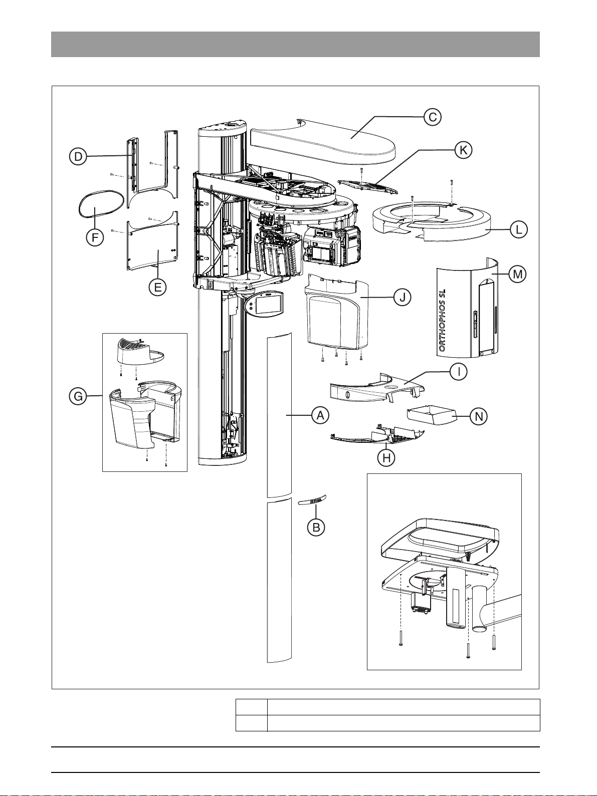
3.1.8 Covers
When removing covers, always remember that direct sunlight or bright
room lighting can cause system malfunctions due to activated light
barriers. Therefore: avoid direct sunlight and bright room lighting above
the unit!
Reattach all covers. When attaching the covers: be sure to screw the
sheet metal cover back on.
IMPORTANT: For reasons of electromagnetic compatibility, be sure to
fasten all screws.
63 03 510 D3352
D3352.076.03.11.02 09.2016
41
Page 42
3Unit description Sirona Dental Systems GmbH
3.1Hardware Service Manual ORTHOPHOS XG 3D / Ceph
A Profile covers, top and bottom
B Intermediate piece
42 D3352.076.03.11.02 09.2016
63 03 510 D3352
Page 43

Sirona Dental Systems GmbH 3Unit description
Service Manual ORTHOPHOS XG 3D / Ceph 3.1Hardware
C Arm cover, top
D Slide cover, top rear
E Slide cover, bottom rear
F Slide cover, center rear
G Sensor cover, complete
H Support cover, bottom
I Support cover, top
J Tube assembly cover
K Tube assembly, cover
L Ring cover
M Slide cover, complete
NDrawer
O Cover, Ceph
bеЦдблЬ
63 03 510 D3352
D3352.076.03.11.02 09.2016
43
Page 44

3Unit description Sirona Dental Systems GmbH
3.1Hardware Service Manual ORTHOPHOS XG 3D / Ceph
3.1.9 Technical Data
Unit data, power, times
Unit data
Model designation: ORTHOPHOS XG 3D/Ceph
Nominal voltage: 200 – 240 V
Permissible fluctuation: ± 10%
Permissible drop under load: 10%
Rated current: 12 A
Rated power: 2 kW at 90 kV/12 mA with any radiation
time
Nominal frequency: 50/60 Hz
Mains resistance: max. 0.8 ohms
Main building fuse: 25 A slow-blow (16 A for single line)
Power consumption: 2 kVA
Power output of tube
assembly:
Tube voltage: 60 – 90 kV (for 90 kV max. 12 mA)
Tube current: 3 – 16 mA (for 16 mA max. 66 kV)
Maximum setting range: 60 kV / 3 mA to 90 kV / 12 mA
High-voltage waveform: High-frequency multipulse
Program duration: see Operating Instructions, section on
Exposure time: see Operating Instructions, section on
Image acquisition scale: For P1, normal dental arch (slice center)
Exposure time for a
cephalometric image:
Image acquisition scale for a
cephalometric image:
90 kV/12 mA = 1080 W with any radiation
time
Residual ripple ≤ 4 kV
"Program values"
"Program values"
approx. 1:1.19, i.e. the acquired image is
magnified by approx. 19% on average
compared to reality.
14.9 s max.
approx. 1:1.1, i.e. the acquired image is
magnified by approx. 10% on average
compared to reality.
3D X-ray tube
Total filtration of X-ray tube
assembly:
Focal spot size as specified
> 2.5 AI / 90 IEC 60522
0.3 mm Cu for volume exposures
0.5
in IEC 60336, measured in
the central X-ray beam:
44 D3352.076.03.11.02 09.2016
63 03 510 D3352
Page 45

Sirona Dental Systems GmbH 3Unit description
Service Manual ORTHOPHOS XG 3D / Ceph 3.1Hardware
Marking of focal spot:
Source-skin distance > 200 mm (8“)
Automatic exposure
blocking:
The duration of automatic exposure
blocking (cooling period) depends on the
set kV/mA level and the actual exposure
time. Depending on the tube load,
interval times of 8 s to 300 s are
automatically set by the system.
A countdown of the waiting time is
displayed on the control panel.
Operating unit data, 200 W long-term power output
Class I device
Degree of protection against
electric shock:
Degree of protection against
ingress of water:
Type B device
Ordinary equipment (without protection
against ingress of water)
Year of manufacture:
bеЦдблЬ
(on the rating plate)
Operating mode: Continuous operation
Long-term power output: 200 W
Anode material: Tungsten
Exposure parameters for
2 mA / 90 kV
determining leakage
radiation:
Transport and storage
Transport and storage
-10°C – +70°C (14°F – 158°F)
temperature:
Air humidity: 10% – 95%
Admissible operating
temperature:
X-ray tube and PAN sensor
Acc. to IEC 60601-1 between +10 °C and
+40 °C (50 °F – 104 °F)
X-ray tube
SR 90 / 15 from Siemens or OCX 100 CEI
63 03 510 D3352
D3352.076.03.11.02 09.2016
45
Page 46

3Unit description Sirona Dental Systems GmbH
3.1Hardware Service Manual ORTHOPHOS XG 3D / Ceph
PAN Sensor
Digital CCD line sensor, repluggable for panoramic exposure technique
Active sensor area, Pan type: 138 mm x 6.48 mm
Detail resolution: 0.027 mm pixel size
Focus-sensor distance: 497 mm
Flat Panel Detector
Flat Panel Detector
Digital Flat Panel Detector with CMOS technology, integrated for 3D
exposure technique
Active sensor area type 3D: 125 mm x 125 mm
Detail resolution: 0.1 mm pixel size
Focus-sensor distance: 530 mm
Max. filtration in front of
<1.2mm Al
sensor:
Ceph sensor
Ceph sensor
Digital CCD line sensor, repluggable for panoramic or ceph exposure
technique
Active sensor area, Ceph
230 mm x 6.48 mm
type:
Detail resolution: 0.027 mm pixel size
Focus-sensor distance: 1,714 mm
Diagrams
46 D3352.076.03.11.02 09.2016
63 03 510 D3352
Page 47

Sirona Dental Systems GmbH 3Unit description
Service Manual ORTHOPHOS XG 3D / Ceph 3.1Hardware
Cooling curve of tube housing
Cooling curve of X-ray tube
Heating curve of tube housing
Central X-ray beam and anode angle
bеЦдблЬ
63 03 510 D3352
D3352.076.03.11.02 09.2016
47
Page 48

3Unit description Sirona Dental Systems GmbH
3.1Hardware Service Manual ORTHOPHOS XG 3D / Ceph
System requirements for SIDEXI S
Minimum PC system requirements for SIDEXIS
Processor: DualCore 1.6 GHz
RAM 2 GB
Free hard disk
5 GB for SIDEXIS installation and database
storage:
Removable
CD/DVD writer
medium:
Operating system: Windows XP Professional, 32-bit, SP3
Windows 7 Professional, 32-bit or 64-bit (64-bit
version not tested)
Windows 7 Ultimate, 32-bit or 64-bit
Graphics card: > 512 MB, minimum resolution 1280 x 1024 pixels,
16.7 million colors (TrueColor)
Screen: Suitable for diagnosis applications
Network card: Network RJ45, 100 MBit/s
USB port: For Version 1.1 and higher, required for USB
components only
Software: Internet Explorer 6.0, SP1
Acrobat Reader 8.0, contained on CD, required for
the PDF test report function
System requirements for GALAXI S
Requirements for GALAXIS PC system
Minimum requirements Recommended
configuration
Processor: DualCore from 2 GHz QuadCore from 2 GHz
RAM 4 GB 8 GB
Hard disk storage: 500 GB 1 TB
Removable
DVD writer
medium:
Operating system: Windows XP
Professional, 32-bit, SP3
Windows 7 Ultimate,
64-bit
Windows 7 Professional,
32-bit or 64-bit
Graphics card: external (no chipset graphics), > 512 MB, minimum
resolution 1280x1024 pixels, 16.7 mil. colors
(TrueColor), Shader Model 3 for advanced
rendering in GALILEOS Implant
Screen: Suitable for diagnostic applications
Network card: Network RJ45, 100 MBit/sNetwork RJ45, 1 GBit/s
48 D3352.076.03.11.02 09.2016
63 03 510 D3352
Page 49
Sirona Dental Systems GmbH 3Unit description
Service Manual ORTHOPHOS XG 3D / Ceph 3.2Firmware
Main software V04.03.00
3.2
Firmware
Any software combinations other than those listed here are not allowed.
If a module software version does not match the main software version,
the main software version is identified with an asterisk on the info screen
(e.g. 04.03.01*).
Software versions: XG 3D
ORTHOPHOS XG 3D Remote control
Board Module software Board Module software
DX11 V04.03.00 DX42 V02.52.04
DX11-FPGA V01.03.00
DX6 V03.03.07
DX61 V03.05.00
DX7 V02.74.07
DX7-L0 V02.29.00
DX7-L1 V02.29.00
DX7-L2 V02.27.00
DX7-L3 V02.27.00
DX7-L4 V02.04.00
DX7-L5 V02.02.00
DX71 V02.52.01
DX81 V02.33.00
DX81-FPGA V03.08.00
DX88 V03.00.03
DX88-FPGA V01.23.00
DX91 V02.44.00
bеЦдблЬ
SIDEXIS XG XG3D
Workstation software
V2.5.1
V2.5.2
63 03 510 D3352
D3352.076.03.11.02 09.2016
V1.0
V1.1
RCU
Server software
V1.8
V2.0
GALILEOS Software
Compatibility Update
V1.7.4 V1.7.2
GALILEOS
Implant
49
Page 50

3Unit description Sirona Dental Systems GmbH
3.2Firmware Service Manual ORTHOPHOS XG 3D / Ceph
Main software V 04.03.01
ORTHOPHOS XG 3D Remote control
Board Module software Board Module software
DX11 V04.03.00 DX42 V02.52.04
DX11-FPGA V01.03.00
DX6 V03.04.00
DX61 V03.05.00
DX7 V02.74.07
DX7-L0 V02.29.00
DX7-L1 V02.29.00
DX7-L2 V02.27.00
DX7-L3 V02.27.00
DX7-L4 V02.04.00
DX7-L5 V02.02.00
DX71 V02.52.01
DX81 V02.33.00
DX81-FPGA V03.08.00
DX88 V03.00.03
DX88-FPGA V01.23.00
DX91 V02.44.00
SIDEXIS XG XG3D
Workstation software
V2.5.1
V2.5.2
V1.0
V1.1
RCU
Server software
V1.8
V2.0
GALILEOS Software
Compatibility Update
GALILEOS
Implant
V1.7.4 V1.7.2
50 D3352.076.03.11.02 09.2016
63 03 510 D3352
Page 51

Sirona Dental Systems GmbH 3Unit description
Service Manual ORTHOPHOS XG 3D / Ceph 3.2Firmware
Main software V04.04.00
ORTHOPHOS XG 3D Remote control
Board Module software Board Module software
DX11 V04.04.01 DX42 V02.54.00
DX11-FPGA V01.03.00
DX6 V03.05.00
DX61 V04.01.00
DX7 V02.77.01
DX7-L0 V02.29.00
DX7-L1 V02.29.00
DX7-L2 V02.27.00
DX7-L3 V02.27.00
DX7-L4 V02.04.00
DX7-L5 V02.02.00
DX71 V02.54.00
DX81 V02.33.00
DX81-FPGA V03.08.00
DX88 V03.02.00
DX88-FPGA V01.30.00
DX91 V02.44.00
bеЦдблЬ
SIDEXIS XG XG3D
Workstation software
V2.5.2
V2.5.3
V1.1 V2.0 V1.8
RCU
Server software
GALILEOS
Implant
63 03 510 D3352
D3352.076.03.11.02 09.2016
51
Page 52

3Unit description Sirona Dental Systems GmbH
3.2Firmware Service Manual ORTHOPHOS XG 3D / Ceph
Main software V04.07.00
ORTHOPHOS XG 3D Remote control
Board Module software Board Module software
DX11 V04.07.00 DX42 V02.55.00
DX11-FPGA V01.03.00
DX6 V03.05.00
DX61 V04.02.00
DX7 V02.79.00
DX7-L0 V02.29.00
DX7-L1 V02.29.00
DX7-L2 V02.27.00
DX7-L3 V02.27.00
DX7-L4 V02.04.00
DX7-L5 V02.02.00
DX71 V02.54.01
DX81 V02.33.00
DX81-FPGA V03.08.00
DX88 V03.03.00
DX88-FPGA V01.31.00
DX91 V02.44.00
SIDEXIS XG XG3D
Workstation software
V2.5.2
V1.2 V2.1 V1.9
V2.5.3
RCU
Server software
GALILEOS
Implant
52 D3352.076.03.11.02 09.2016
63 03 510 D3352
Page 53

Sirona Dental Systems GmbH 3Unit description
Service Manual ORTHOPHOS XG 3D / Ceph 3.2Firmware
Main software V04.07.01
ORTHOPHOS XG 3D Remote control
Board Module software Board Module software
DX11 V04.07.01 DX42 V02.55.00
DX11-FPGA V01.03.00
DX6 V03.05.00
DX61 V04.02.00
DX7 V02.79.00
DX7-L0 V02.29.00
DX7-L1 V02.29.00
DX7-L2 V02.27.00
DX7-L3 V02.27.00
DX7-L4 V02.04.00
DX7-L5 V02.02.00
DX71 V02.54.01
DX81 V02.33.00
DX81-FPGA V03.08.00
DX88 V03.02.05
DX88-FPGA V01.31.00
DX91 V02.44.00
bеЦдблЬ
SIDEXIS XG XG3D
Workstation software
V2.5.2
V2.5.3
V1.2 V2.1 V1.9
RCU
Server software
GALILEOS
Implant
63 03 510 D3352
D3352.076.03.11.02 09.2016
53
Page 54

3Unit description Sirona Dental Systems GmbH
3.2Firmware Service Manual ORTHOPHOS XG 3D / Ceph
Main software V04.09.02
ORTHOPHOS XG 3D Remote control
Board Module software Board Module software
DX11 V04.09.02 DX42 V02.56.02
DX11-FPGA V01.03.00
DX6 tube
V03.06.03
assembly 1.0
DX6 tube
V04.07.01
assembly 2.0
DX61 V04.02.00
DX7 V02.80.05
DX7-L0 V02.29.00
DX7-L1 V02.29.00
DX7-L2 V02.27.00
DX7-L3 V02.27.00
DX7-L4 V02.04.00
DX7-L5 V02.02.00
DX71 V02.54.03
DX81 V02.33.00
DX81-FPGA V03.08.00
DX88 V03.02.05
DX88-FPGA V01.31.00
DX91 V02.44.00
SIDEXIS XG XG3D
Workstation software
V2.5.2
V1.2 V2.2 V1.9 SP1
V2.5.3
V2.5.6
RCU
Server software
GALILEOS
Implant
54 D3352.076.03.11.02 09.2016
63 03 510 D3352
Page 55

Sirona Dental Systems GmbH 3Unit description
Service Manual ORTHOPHOS XG 3D / Ceph 3.2Firmware
Main software V04.12.00
ORTHOPHOS XG 3D Remote control
Board Module software Board Module software
DX11 V04.12.00 DX42 V02.56.04
DX11-FPGA V01.04.00
DX6 tube
assembly 1.0
DX6 tube
assembly 2.0
DX61 V04.03.00
DX7 V02.80.07
DX7-L0 V02.29.00
DX7-L1 V02.29.00
DX7-L2 V02.27.00
DX7-L3 V02.27.00
DX7-L4 V02.04.00
DX7-L5 V02.02.00
DX71 V02.54.03
DX81 V02.33.00
DX81-FPGA V03.08.00
DX88 V03.02.07
DX88-FPGA V01.31.00
DX91 V02.44.00
V03.07.03
V04.09.00
bеЦдблЬ
SIDEXIS XG XG3D
Workstation software
V2.5.6 V1.3 V2.3 V1.9 SP1
RCU
Server software
GALILEOS
Implant
63 03 510 D3352
D3352.076.03.11.02 09.2016
55
Page 56

3Unit description Sirona Dental Systems GmbH
3.2Firmware Service Manual ORTHOPHOS XG 3D / Ceph
Main software V04.14.00
ORTHOPHOS XG 3D Remote control
Board Module software Board Module software
DX11 V04.14.00 DX42 V02.58.02
DX11-FPGA V01.04.00
DX6 tube
V03.08.00
assembly 1.0
DX6 tube
V04.09.07
assembly 2.0
DX61 V04.04.00
DX7 V02.82.01
DX7-L0 V02.31.00
DX7-L1 V02.31.00
DX7-L2 V02.29.00
DX7-L3 V02.29.00
DX7-L4 V02.06.00
DX7-L5 V02.02.00
DX71 V02.55.02
DX81 V02.33.00
DX81-FPGA V03.08.00
DX88 V03.03.07
DX88-FPGA V01.31.00
DX91 V02.45.00
SIDEXIS XG XG3D
Workstation software
RCU
Server software
GALILEOS
Implant
V2.5.6 V1.4 V2.4 V1.9 SP1
56 D3352.076.03.11.02 09.2016
63 03 510 D3352
Page 57

Sirona Dental Systems GmbH 3Unit description
Service Manual ORTHOPHOS XG 3D / Ceph 3.2Firmware
Main software V04.14.01
ORTHOPHOS XG 3D Remote control
Board Module software Board Module software
DX11 V04.14.00 DX42 V02.58.02
DX11-FPGA V01.04.00
DX6 tube
assembly 1.0
DX6 tube
assembly 2.0
DX61 V04.04.00
DX7 V02.82.01
DX7-L0 V02.31.00
DX7-L1 V02.31.00
DX7-L2 V02.29.00
DX7-L3 V02.29.00
DX7-L4 V02.06.00
DX7-L5 V02.04.00
DX71 V02.55.02
DX81 V02.33.00
DX81-FPGA V03.08.00
DX88 V03.03.07
DX88-FPGA V01.31.00
DX91 V02.45.00
V03.08.00
V04.09.07
bеЦдблЬ
SIDEXIS XG XG3D
Workstation software
V2.5.6 V1.4 V2.4 V1.9 SP1
RCU
Server software
GALILEOS
Implant
63 03 510 D3352
D3352.076.03.11.02 09.2016
57
Page 58

3Unit description Sirona Dental Systems GmbH
3.2Firmware Service Manual ORTHOPHOS XG 3D / Ceph
Main software V04.14.02
ORTHOPHOS XG 3D Remote control
Board Module software Board Module software
DX11 V04.14.00 DX42 V02.58.02
DX11-FPGA V01.04.00
DX6 tube
V03.08.00
assembly 1.0
DX6 tube
V04.09.07
assembly 2.0
DX61 V04.04.00
DX7 V02.82.01
DX7-L0 V02.31.00
DX7-L1 V02.31.00
DX7-L2 V02.29.00
DX7-L3 V02.29.00
DX7-L4 V02.06.00
DX7-L5 V02.04.00
DX71 V02.55.02
DX81 V02.33.00
DX81-FPGA V03.08.00
DX88 V03.03.07
DX88-FPGA V01.31.00
DX91 V02.45.00
SIDEXIS XG SIDEXIS 4 XG3D
Workstation software
RCU
Server software
GALILEOS
Implant
V2.6.2 V4.1.2 V1.5 V2.5 V1.9 SP1
58 D3352.076.03.11.02 09.2016
63 03 510 D3352
Page 59

Sirona Dental Systems GmbH 3Unit description
Service Manual ORTHOPHOS XG 3D / Ceph 3.2Firmware
Main software V04.14.03
ORTHOPHOS XG 3D Remote control
Board Module software Board Module software
DX11 V04.16.06 DX42 V02.58.02
DX11-FPGA V02.03.00
DX6 tube
assembly 1.0
DX6 tube
assembly 2.0
DX61 V04.04.00
DX7 V02.82.02
DX7-L0 V02.32.00
DX7-L1 V02.31.00
DX7-L2 V02.29.00
DX7-L3 V02.29.00
DX7-L4 V02.06.00
DX7-L5 V02.04.00
DX71 V02.55.02
DX81 V02.33.00
DX81-FPGA V03.08.00
DX88 V03.03.07
DX88-FPGA V01.31.00
DX91 V02.45.00
V03.08.00
V04.10.06
bеЦдблЬ
SIDEXIS XG SIDEXIS 4 XG3D
Workstation software
V2.6.2 V4.1.2 V1.5 V2.5 V1.9 SP1
RCU
Server software
GALILEOS
Implant
63 03 510 D3352
D3352.076.03.11.02 09.2016
59
Page 60

4General operating procedures Sirona Dental Systems GmbH
4.1Switching the unit on Service Manual ORTHOPHOS XG 3D / Ceph
General operating procedures
4
4.1
Switching the unit on
WARNING
X-rays
Be sure to observe the radiation protection regulations applicable in
your country.
➢ No person may be positioned in the unit when it is switched on.
NOTICE
Damage to the unit
Check the room height before you raise the unit.
➢ If the room height is less than 2.27 m (89 3/8") or 2.30 m (90 1/2")
for installation with the floor stand, you must limit the maximum
travel height [ → 325].
NOTICE
Fluctuations in temperature can cause condensation to form in the unit.
Electrical components are destroyed by short circuits.
➢ Do not switch the unit on until the temperature of the unit has
adapted to the ambient temperature and the condensation has
evaporated.
Waiting time when switchin g on and off
NOTICE
The unit must not be switched on/off constantly.
Constant switching on and off reduces the service life of individual unit
components and results in increased power consumption.
➢ After switching the unit off, wait for approx. 60 seconds before
switching it on again.
Switching the unit on: XG 3D/3D ready
NOTICE
The surface of the touchscreen is sensitive.
The touchscreen can be damaged or its surface scratched.
➢ Never use pointed objects such as ballpoint pens, pencils, etc. to
operate the touchscreen.
➢ Only use your fingertips to operate the touchscreen.
IMPORTANT
After the unit is switched on, the touchscreen has only limited readability
for several minutes until the background lighting has completed its
warm-up phase.
After the unit is switched off with the main switch, the touchscreen
remains lit for approx. another 3 to 5 seconds.
63 03 510 D3352
60 D3352.076.03.11.02 09.2016
Page 61

Sirona Dental Systems GmbH 4General operating procedures
T
R
C
B
A
Service Manual ORTHOPHOS XG 3D / Ceph 4.1Switching the unit on
IMPORTANT
After switch-on, the unit requires approx. 1 min. of warm-up time.
At the same time, the self-adjustment routine for the mechanics and the
electronics of the unit is performed. If a key is pressed during the selfadjustment routine, an error message will display on the control panel.
1. Turn the main switch (A) to position I.
2. Wait for approx. 1 minute.
ª The radiation indicator X-ray (C) lights up for approx. one second
as a functional check.
ª After approx. 2 seconds, the green LED B in the upper part of the
control panel lights up. This LED remains lit as long as the unit is
on.
ª The start screen is displayed on the touchscreen for several
seconds.
ª The program selection is then displayed on the touchscreen.
ª The forehead support and temple supports are completely open.
3. Check whether the patient symbols on the touchscreen can be
selected in exactly the right position.
If problems occur during selection, adjust the touchscreen [ → 244].
4. Press the R key.
ª The unit moves to its starting position.
5. Switch on the PC.
6. Start SIDEXIS.
ª As long as no connection has been made to SIDEXIS, the
message
"Switch SIDEXIS to ready for exposure state"
displayed in the comment line of the control panel.
4.1.1 Factory setting after switch-on
Factory setting after switch-on: XG 3D/3D ready
The unit has the following factory configuration on delivery:
● The acoustic signal for end of exposure is activated.
● The unit language is preconfigured as ordered.
● The preview image is switched on.
● The welcome screen is switched on.
● The first name, last name and date of birth lines are displayed on the
welcome screen.
If the custo mer requ i res a di f ferent co nfigura tio n, this c a n be implemented
via service routine S017.
bеЦдблЬ
is
63 03 510 D3352
D3352.076.03.11.02 09.2016
61
Page 62

4General operating procedures Sirona Dental Systems GmbH
4.2Updating the unit firmware Service Manual ORTHOPHOS XG 3D / Ceph
4.2
Updating the unit firmware
IMPORTANT
Downgrading to older versions
Downgrading the unit software version V04.14.00 or higher to an older
version is not a simple process. However, if this is essential, please get
in contact with the SIRONA Customer Service Center (CSC) in
advance.
XG 3D software update
Read the information provided on the firmware CD supplied with the unit
and on the SIRONA dealer page on the Internet very carefully. These
sources always contain the latest information on software updates.
1. Start the
"SIDEXIS XG"
2. Click
"Configuration of the X-ray components"
ª The
"SIDEXIS Manager"
.
"Configuration of the X-ray components"
under "Start"/"Programs"/"SIDEXIS"/
.
menu opens.
3. Select the
4. Click on the
ª The dialog box for entering the service password opens.
5. Enter the service password.
Enter the first 4 digits of the current system date in reverse order as
the service password (e.g. on 05/24/1995, 5042 must be entered as
the service password.
If an incorrect service password or no password at all is entered, the
limited update menu for users will be started. This includes only the
possibility for an automatic update [ → 67].
ª The dialog box for selecting the installation source opens.
"Attributes"
tab.
"Software update"
button.
63 03 510 D3352
62 D3352.076.03.11.02 09.2016
Page 63

Sirona Dental Systems GmbH 4General operating procedures
Service Manual ORTHOPHOS XG 3D / Ceph 4.2Updating the unit firmware
6. Click on the button with the 3 dots.
ª The dialog box for selecting the update file opens.
7. Select the desired update file from the list and confirm the selection
with the
The update file is located on the unit software CD. It is delivered with
each DX11 replacement board and also included in the country set.
The contents of the CD can be downloaded from the Dealer domain
of the SIRONA Internet home page (under Products/Imaging
systems): www.sirona.com
8. Click on the
ª The software manager opens.
ª The modules and their current software versions are displayed in
ª In the structure tree on the left (B) of the software manager, the
"Open"
the action window (A) of the software manager.
update modes
can now be selected.
button.
"Next"
button.
"Automatic" , "Main version"
an d
"Module update"
bеЦдблЬ
63 03 510 D3352
D3352.076.03.11.02 09.2016
63
Page 64

4General operating procedures Sirona Dental Systems GmbH
4.2Updating the unit firmware Service Manual ORTHOPHOS XG 3D / Ceph
IMPORTANT
In main software V04.09.02 and higher, two versions of the DX6
assembly (tube assembly 1.0 and tube assembly 2.0) appear in the
action window (A) of the software manager. Depending upon which tube
assembly has been installed, one of the versions is displayed with a red
bar and the other with a green bar.
9. Select the desired mode for the software update (see chapter entitled
"Update mode [ → 67]").
NOTICE
Unit inoperability!
Before starting the software update, make sure that no unit movements
are active. Otherwise the system may become inoperable in rare cases.
The X-ray detector must be installed as part of the update. Exposure
readiness must be deselected in SIDEXIS XG and the unit must not
already be in service mode.
10. Click on the
"Start SW update"
button.
64 D3352.076.03.11.02 09.2016
63 03 510 D3352
Page 65

Sirona Dental Systems GmbH 4General operating procedures
Service Manual ORTHOPHOS XG 3D / Ceph 4.2Updating the unit firmware
ª The update is started. A message box informs you when the
update process is completed.
11. Confirm the update by clicking on the
ª A message in the software manager notifies you that a unit restart
is required to activate the software update you performed.
"OK"
button.
bеЦдблЬ
NOTICE
Effectiveness of the software update
The unit must be restarted after every software update. The new DX11
version will run only after the unit has been rebooted (see also chapter
"Measures following replacement of boards [ → 432]").
Any errors with the consecutive numbers 01, 03, 04, 06, or 07 displayed
immediately following the software update may be ignored. If these
messages appear again after the system is rebooted, please carry out
troubleshooting as described in the "Error messages [ → 91]" section.
If any conspicuous problems occur in connection with system handling
after the software update and unit reboot has been completed, please
repeat the software update immediately.
12. Click on the
whether the update was successfully performed.
If it features entries such as "Update of DXxx failed!", please perform
the update again. Repeat this procedure as often as necessary until
the "failed messages" no longer appear.
"Show logfile"
button and use the log files to check
63 03 510 D3352
D3352.076.03.11.02 09.2016
65
Page 66

4General operating procedures Sirona Dental Systems GmbH
4.2Updating the unit firmware Service Manual ORTHOPHOS XG 3D / Ceph
13. Restart the unit now.
14. Use the software manager or service routine S008.2 (see section
"Firmware [ → 49]") to test whether all modules have the current
program version (see section "Check program releases [ → 69]".
15. Call up "Further Details" [ → 71].
This generates an XML file (with the system parameters) which is
saved in the PDATA/.../P2K_Config directory [ → 71] under the
network name of the unit.
66 D3352.076.03.11.02 09.2016
63 03 510 D3352
Page 67

Sirona Dental Systems GmbH 4General operating procedures
Service Manual ORTHOPHOS XG 3D / Ceph 4.2Updating the unit firmware
4.2.1 Update mode
Update mode: XG 3D
IMPORTANT
Update mode Module update is only intended for internal Sirona
purposes and is not activated for User or Service mode.
In
Service mode
[ → 188]), the update manager supports two modes for updating the
software; these can be selected via the elements
version"
in the structure tree:
(accessible only by entering the Service Password
"Automatic"
and
"Main
● Automatic
The software of all components is automatically
software version
The right window displays a list of the modules, their installed
software version and the latest software version offered by the
update.
.
updated to the latest
bеЦдблЬ
63 03 510 D3352
D3352.076.03.11.02 09.2016
67
Page 68

4General operating procedures Sirona Dental Systems GmbH
4.2Updating the unit firmware Service Manual ORTHOPHOS XG 3D / Ceph
● Main version
The software can be updated or downgraded using this menu.
This update mode is required, among other things, if a replacement
module arrives from the warehouse and features a newer release
than the existing main release of the unit. In this case, a main version
update to the overall unit status (displayed on the info screen) must
be performed for the corresponding component with the appropriate
update file (*.SUI). The module is then reprogrammed.
User mode
In
update manager only supports
(which can be accessed without a service password), the
"Automatic"
update mode.
The colored bars in front of the software releases indicate their validity
(see chapter entitled "Check program releases [ → 69]").
68 D3352.076.03.11.02 09.2016
63 03 510 D3352
Page 69

Sirona Dental Systems GmbH 4General operating procedures
Service Manual ORTHOPHOS XG 3D / Ceph 4.2Updating the unit firmware
4.2.2 Check program releases
Check program releases: XG 3D
You can use the action window (A) of the software manager to check
which modules are connected to the unit and what their latest program
release is.
bеЦдблЬ
63 03 510 D3352
D3352.076.03.11.02 09.2016
69
Page 70

4General operating procedures Sirona Dental Systems GmbH
4.2Updating the unit firmware Service Manual ORTHOPHOS XG 3D / Ceph
Modules which are connected and whose program release corresponds
to the latest main software version (see chapter entitled "Firmware
[ → 49]" are identified by a continuous green bar.
Modules which the system does not recognize are identified by a broken
red bar.
If the actual status of the module cannot be polled for the update, the
actual SW version will be displayed as = V00:00.
If a module has a hardware incompatibility to the program status to be
programmed or the software version on the module is newer than the one
in the update file, this will be indicated by a red triangle with an
exclamation mark.
If the version of the selected update file is lower than the current software
version of the unit, then there will be no display in the right window. The
downgrade required in this case is possible only via
"Main version"
mode.
70 D3352.076.03.11.02 09.2016
63 03 510 D3352
Page 71

Sirona Dental Systems GmbH 4General operating procedures
Service Manual ORTHOPHOS XG 3D / Ceph 4.3Opening "Details"
4.3
Opening "Details"
Opening details XG 3 / 5 / 3D / 3D ready
1. Start the
"SIDEXIS XG"
2. Click
ª The
"SIDEXIS Manager"
.
"Configuration of the X-ray components"
"Configuration of the X-ray components"
under "Start"/"Programs"/"SIDEXIS"/
.
menu opens.
bеЦдблЬ
3. Select the
4. Click on the
ª The current parameters are read from the unit and filed in an XML
"Attributes"
"Details..."
file under the network name of the unit in the PDATA/.../
P2K_Config folder. The process can take up to 30 seconds. After
the parameters are read, an editor displaying the data is opened
automatically.
tab.
button.
63 03 510 D3352
D3352.076.03.11.02 09.2016
71
Page 72

4General operating procedures Sirona Dental Systems GmbH
4.3Opening "Details" Service Manual ORTHOPHOS XG 3D / Ceph
72 D3352.076.03.11.02 09.2016
63 03 510 D3352
Page 73

Sirona Dental Systems GmbH 4General operating procedures
Service Manual ORTHOPHOS XG 3D / Ceph 4.4Setup of an X-ray component
4.4
Setup of an X-ray component
Since it is addressable via the network, the X-ray component can in
principle be activated for X-ray image acquisition by any of the PCs
connected to the network.
The program SiXABCon is used to manage networkable X-ray
components. It can be executed on any PC in the network on which
SIDEXIS XG has been installed.
IMPORTANT: In order to avoid IP address conflicts, you should never
operate several networkable X-ray components in the network using the
same IP address. Each X-ray component needs to be assigned a unique
IP address.
Factory setting of the TCP/IP address of the unit:
192.168.15.240 (subnet mask: 255.255.255.0)
Checking existing IP addresses
To find out whether an IP address already exists in the network, enter the
"PING" function in the input prompt (DOS window).
all
1. Switch on
components) which are being operated in the network.
2. Invoke the input prompt (DOS window) from a network computer.
3. At the input prompt, enter "ping" followed by the address to be
checked and then press the Enter key.
Example: "ping 192.168.15.13"
ª If a network device responds, then this address has already been
assigned.
network devices (computers, printers, X-ray
bеЦдблЬ
63 03 510 D3352
D3352.076.03.11.02 09.2016
73
Page 74

4General operating procedures Sirona Dental Systems GmbH
4.4Setup of an X-ray component Service Manual ORTHOPHOS XG 3D / Ceph
4.4.1 Selecting an X-ray component
1. Switch all networkable X-ray components off.
2. Start the
"SIDEXIS"
/
3. Click
ª The
"SIDEXIS Manager"
.
by selecting
"start"
"Configuration of the X-ray components"
"Configuration of the X-ray components"
/
"Program Files"
.
menu opens.
4. Select the
5. Select the name of the desired X-ray component in the
down menu ("XG3D" in the example); then click the
button.
or
➢ Select the text
"Attributes"
"Add component"
component in the
tab.
"Name"
"Add component"
under the desired X-ray
pull-down menu.
"Name"
pull-
ª The password dialog box appears.
63 03 510 D3352
74 D3352.076.03.11.02 09.2016
Page 75

Sirona Dental Systems GmbH 4General operating procedures
Service Manual ORTHOPHOS XG 3D / Ceph 4.4Setup of an X-ray component
6. Enter the service password [ → 188] and confirm your input by clicking
"OK"
the
ª The
ª The
button.
"Device configuration"
"Boot service"
element is selected automatically.
menu opens.
bеЦдблЬ
63 03 510 D3352
D3352.076.03.11.02 09.2016
75
Page 76

4General operating procedures Sirona Dental Systems GmbH
4.4Setup of an X-ray component Service Manual ORTHOPHOS XG 3D / Ceph
Boot service
IMPORTANT
Automatic addition and setup of the X-ray component via the boot
service functions properly only if the unit is started with the default
factory-set IP address.
If the IP address already has been changed, reset it to the factory setting
via service routine S037.2 or use the elements
"Add component manually"
service".
(see section on "Alternatives to the boot
"Automatic search"
or
✔ The element
1. Switch the unit on.
ª The unit is detected in the network and the values for the IP
address, subnet mask and standard gateway are automatically
imported to the input fields of the menu.
"Boot service"
is selected in the structure tree.
IMPORTANT
If the unit is not automatically detected in the network, it is possible to
manually assign a static IP address via service routine S037.4.
IMPORTANT
Each unit must be assigned a unique IP address in the network.
2. If you want to, you can enter an individual IP address in the
address"
with the cursor.
ª Default values suitable for the IP address are automatically
3. You can either overwrite the default values in the input fields or leave
them unchanged, depending on the network involved.
input field and then click into one of the other input fields
entered in the
fields.
"Subnet mask"
and
"Standard Gateway"
"IP
input
63 03 510 D3352
76 D3352.076.03.11.02 09.2016
Page 77
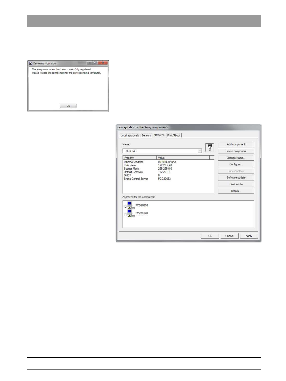
Sirona Dental Systems GmbH 4General operating procedures
Service Manual ORTHOPHOS XG 3D / Ceph 4.4Setup of an X-ray component
4. Select the desired RCU in the
menu.
5. Confirm the settings by clicking on the
ª The settings are saved.
ª The
6. Confirm this dialog by clicking on the
7. Close the
button.
ª The new X-ray component appears in the device list of the menu
"Device configuration"
you that the configuration of the X-ray component has been
completed successfully.
"Device configuration"
"Configuration of the X-ray component"
"Sirona Control Server"
"Save values"
dialog window appears and informs
"OK"
button.
menu by clicking on the
.
drop-down
button.
"Quit"
bеЦдблЬ
63 03 510 D3352
D3352.076.03.11.02 09.2016
Alternatives to the boot service
As an alternative to adding new X-ray components via the boot service,
you also can add them via the
manually"
function.
"Automatic search"
or t he
"Add component
77
Page 78

4General operating procedures Sirona Dental Systems GmbH
4.4Setup of an X-ray component Service Manual ORTHOPHOS XG 3D / Ceph
Automatic search
1. Select the
ª The network is searched for existing X-ray components. All X-ray
2. Select the desired X-ray component from the list.
ª The values for the IP address, subnet mask and standard
3. Select the desired RCU in the
menu.
4. Confirm the settings by clicking on the
ª The settings are saved.
ª The
5. Confirm this dialog by clicking on the
6. Close the
button.
ª The new X-ray component appears in the device list of the menu
"Automatic search"
components found appear in the menu list.
gateway are automatically imported to the input fields of the
menu.
"Device configuration"
you that the configuration of the X-ray component has been
completed successfully.
"Device configuration"
"Configuration of the X-ray component"
element.
"Sirona Control Server"
"Save values"
dialog window appears and informs
"OK"
button.
menu by clicking on the
.
drop-down
button.
"Quit"
78 D3352.076.03.11.02 09.2016
63 03 510 D3352
Page 79

Sirona Dental Systems GmbH 4General operating procedures
Service Manual ORTHOPHOS XG 3D / Ceph 4.4Setup of an X-ray component
Adding the component manually
1. Select the
2. Enter the values in the menu input fields manually.
3. Select the desired RCU in the
menu.
4. Confirm the settings by clicking on the
ª The settings are saved.
ª The
5. Confirm this dialog by clicking on the
6. Close the
button.
ª The new X-ray component appears in the device list of the menu
"Add component manually"
"Sirona Control Server"
"Device configuration"
you that the configuration of the X-ray component has been
completed successfully.
"Device configuration"
"Configuration of the X-ray component"
element.
drop-down
"Save values"
dialog window appears and informs
"OK"
button.
menu by clicking on the
.
button.
"Quit"
bеЦдблЬ
63 03 510 D3352
D3352.076.03.11.02 09.2016
79
Page 80

4General operating procedures Sirona Dental Systems GmbH
4.4Setup of an X-ray component Service Manual ORTHOPHOS XG 3D / Ceph
4.4.2 Approval of the X-ray component
✔ The X-ray component must have been selected [ → 74] via the
"Device configuration"
menu.
➢ Click on the check box in front of the X-ray component that you would
like to enable and accept the setting by clicking on the
ª The X-ray component is enabled.
"Apply"
button.
80 D3352.076.03.11.02 09.2016
63 03 510 D3352
Page 81

Sirona Dental Systems GmbH 4General operating procedures
Service Manual ORTHOPHOS XG 3D / Ceph 4.4Setup of an X-ray component
Checking enablement ➢ To check the communication with the unit, click the
button.
ª If the unit is communicating, a logfile with information on the unit
configuration appears.
"Device info"
bеЦдблЬ
63 03 510 D3352
D3352.076.03.11.02 09.2016
81
Page 82

4General operating procedures Sirona Dental Systems GmbH
4.4Setup of an X-ray component Service Manual ORTHOPHOS XG 3D / Ceph
4.4.3 Deleting an X-ray component
1. Switch all networkable X-ray components off.
2. Start the
"SIDEXIS"
/
3. Click
ª The
"SIDEXIS Manager"
.
by selecting
"start"
"Configuration of the X-ray components"
"Configuration of the X-ray components"
/
"Program Files"
.
menu opens.
4. Select the
5. Select the name of the desired X-ray component in the
down menu ("XG3D" in the example); then click the Delete
component button.
"Attributes"
tab.
"Name"
pull-
82 D3352.076.03.11.02 09.2016
63 03 510 D3352
Page 83

Sirona Dental Systems GmbH 4General operating procedures
Service Manual ORTHOPHOS XG 3D / Ceph 4.5Using demo mode – operation without radiation release
4.5
Using demo mode – operation without radiation release
XG 3 / 5 / 3D / 3D ready
If the unit is to be presented as a demo unit at trade fairs or exhibitions, it
must be ensured that radiation release is blocked.
4.5.1 Switching on demo mode
When operated in demo mode, the unit must not release any radiation.
For this reason, you must take the following safety measures:
Switching on demo mode X G 3D ready / XG 3D
1. Switch off the unit.
DANGER
Perilous shock hazard!
It is essential to switch off the unit and to wait at least another 4 minutes
before taking off the covers of the X-ray tube assembly.
2. Remove the "Rear tube assembly" cover [ → 41].
3. Remove the cover plate of board DX6 [ → 406].
4. Set dip switch S2 (DX6) to position 2.
IMPORTANT: If switch S2 is not set to position 2 in demo mode
before switching off the unit, various error messages will display
when the unit is turned back on.
5. Pull cable L5 (XRAY) off connector J6/J103 (DX6).
ª Radiation release is now no longer possible.
bеЦдблЬ
63 03 510 D3352
D3352.076.03.11.02 09.2016
6. Switch on the unit and check the mode on the info screen.
Demo mode: ON means that: Demo mode is switched on (radiation
release is not possible)
Demo mode: OFF means that: Demo mode is switched off
(radiography, X-ray radiation are possible!)
7. Switch the unit off again and reattach the cover plate and the tube
assembly cover by following the dismantling procedure in reverse
order.
83
Page 84

4General operating procedures Sirona Dental Systems GmbH
4.5Using demo mode – operation without radiation release Service Manual ORTHOPHOS XG 3D / Ceph
4.5.2 Switching off demo mode
Switching off XG 3D / XG 3D ready
1. Switch off the unit.
DANGER
Perilous shock hazard!
It is essential to switch off the unit and to wait at least another 4 minutes
before taking off the covers of the X-ray tube assembly.
2. Remove the "Rear tube assembly" cover [ → 41].
3. Remove the cover plate of board DX6 [ → 406].
4. Set the dip switch S2 (DX6) to position 1.
5. Connect cable L5 (XRAY) to connector J6/J103 (DX6).
ª Radiation release is now once again possible.
6. Switch on the unit and check the mode on the info screen.
Demo mode: ON means that: Demo mode is switched on (radiation
release is not possible)
Demo mode: OFF means that: Demo mode is switched off
(radiography, X-ray radiation are possible!)
7. Switch the unit off again and reattach the cover plate and the tube
assembly cover by following the dismantling procedure in reverse
order.
84 D3352.076.03.11.02 09.2016
63 03 510 D3352
Page 85

Sirona Dental Systems GmbH 4General operating procedures
Service Manual ORTHOPHOS XG 3D / Ceph 4.5Using demo mode – operation without radiation release
4.5.3 Important information for repacking and transport
IMPORTANT
If a used carton on which one of the shockwatch or tiltwatch indicators
has already been tripped is used to package the unit, please make an
entry to that effect on the delivery note.
Cephalometer: XG3D / 3D ready / 5
Packing the cephalometer
1. Call service routine S034.6 [ → 355].
ª After calling the service routine, an inactive progress indicator is
displayed in selection field 1. Selection field 2 shows the
characters "FFFF".
2. Touch the T key (A).
ª The cephalometer moves to the packing position. The procedure
is visualized by an active progress indicator in selection field 1.
ª When the cephalometer has reached its packing position, "0000"
is displayed in selection field 2.
3. Exit the service routine [ → 262].
bеЦдблЬ
63 03 510 D3352
D3352.076.03.11.02 09.2016
85
Page 86

4General operating procedures Sirona Dental Systems GmbH
4.5Using demo mode – operation without radiation release Service Manual ORTHOPHOS XG 3D / Ceph
Panoramic: XG3D
Packing the panoramic unit
IMPORTANT
The bottom edge of the slide cover must be at the same height as the
markings A in the column.
DANGER
Shock hazard!
Be sure to switch off the line power supply before connecting the line
voltage!
1. Switch the unit on and move it to its packing height by actuating the
up/down keys on the control panel.
ª Bite block height = 965 mm (displayed as height on the control
panel)
ª Bottom edge of slide cover = 702 mm
2. Pack the panoramic X-ray unit
(Packing condition (see section "Delivery").
86 D3352.076.03.11.02 09.2016
63 03 510 D3352
Page 87

Sirona Dental Systems GmbH 4General operating procedures
Service Manual ORTHOPHOS XG 3D / Ceph 4.5Using demo mode – operation without radiation release
Packing the X-ray detect or XG 3D
Dismantling and packaging the X-ray detector
IMPORTANT
For transport, pack the X-ray detector in its original packaging (for
packing condition see section "Delivery").
➢ To dismantle the X-ray detector, follow the same procedure as
Installation in reverse order.
Attaching the transport safety device
➢ Install the transport safety device by following the same procedure as
Dismantling in reverse order.
bеЦдблЬ
63 03 510 D3352
D3352.076.03.11.02 09.2016
87
Page 88

5Messages Sirona Dental Systems GmbH
Service Manual ORTHOPHOS XG 3D / Ceph
Messages
5
The different message texts are displayed ...
XG 3D message texts
● On the Easypad touchscreen
● On the display of the remote control
There are 3 groups of message texts:
Help messages (Hx xx):
● Help messages are caused by operator errors.
● The user must take action.
Error messages (Ex yyxx):
● Error messages indicate unit faults.
● The user must take action to eliminate the fault(s).
System messages (Sxxx):
● System messages inform the user about the current operating status
of the unit.
● The user does not have to take any action.
If error messages are displayed on the control panel that are not listed in
this section (such as message 1311), these messages come from the
Windows system. In such cases, you must check whether the firmware
you are using is compatible with the SIDEXIS XG version and run a
software update [ → 62] if necessary.
88 D3352.076.03.11.02 09.2016
63 03 510 D3352
Page 89

Sirona Dental Systems GmbH 5Messages
Service Manual ORTHOPHOS XG 3D / Ceph 5.1Help messages
5.1
Help code Description Actions required
H3 01
H3 07
H3 20
H3 21
H3 22
H3 25
H4 02
H4 03
H4 04
H4 06
"R button, move into starting position"
"Change bite block"
"R button, confirm exposure data"
"Close the door"
"Select quadrant"
"Select region of exposure"
"Plug sensor into Ceph slot"
"Switch SIDEXIS to ready for exposure state"
"Plug in Ceph sensor"
"R button, move into Ceph starting position"
Help messages
Help messages: XG 3D
Help messages are displayed as help codes (Hx xx) on the Easypad
touchscreen or on the remote control display (if available). The codes tell
you how to operate the system if radiation release is not possible due to
a previous operator error.
The following list provides you with an overview of all help codes, their
meaning and the action required to eliminate the corresponding
problems.
IMPORTANT: The measures listed only clear help messages that result
from operator errors. If it is not possible to clear a message by taking the
measures listed, another type of error is the cause. In such cases, you
should run an error diagnosis [ → 94].
● Press the R key.
● Unit moves to starting position.
Remove the occlusal bite block.
● Press the R key.
● Exposure data are confirmed.
● Close door or check door contact.
Then press R key to acknowledge the
message.
● Select quadrant
● Select the center of rotation.
● Check the ceph sensor or plug it into the
cephalometer.
If this message does not disappear even after
the ceph sensor has been plugged in, this
indicates a system error. Perform error
diagnosis as described in the section titled
Troubleshooting [ → 160] .
● Make SIDEXIS XG ready for
exposure.
● Plug the ceph sensor into the cephalometer.
● Press the R key.
bеЦдблЬ
H4 07
H4 08
H4 09
H4 20
63 03 510 D3352
D3352.076.03.11.02 09.2016
"Correct SIDEXIS preselection"
"Select SIDEXIS 3D exposure"
"Select SIDEXIS 2D exposure"
"Get existing exposure"
● Cephalometer moves to starting position.
● Perform alternative program setting.
Select 3D exposure in SIDEXIS XG.
Select 2D exposure in SIDEXIS XG.
IMPORTANT: Do not switch the system off until the
help message has disappeared.
● Get exposure with "Sirona Control Admin" (see
SIDEXIS XG
134).
"Operator’s Manual"
(REF 59 62
89
Page 90

5Messages Sirona Dental Systems GmbH
5.2System messages Service Manual ORTHOPHOS XG 3D / Ceph
5.2
System messages
XG 3D system messages
System codes are only displayed on the remote control. System
messages are displayed in plain text on the Easypad.
System code Description Actions required
XG 3D system message tabl e
S100
S110
"System is starting"
"Exposure not possible"
● Wait, no action required.
● Restart the unit:
1. Switch off the unit.
2. Wait 1 minute.
3. Switch unit on.
4. Repeat procedure
5.3
Status displays
Status displays: XG 3D
Status display on the Easypad Description
Ready for exposure The unit is ready for operation.
Exposure is performed Radiation is released.
Please wait Unit waiting for operational readiness.
Ready for exposure in XX seconds The cooling time countdown is running.
90 D3352.076.03.11.02 09.2016
63 03 510 D3352
Page 91

Sirona Dental Systems GmbH 5Messages
Service Manual ORTHOPHOS XG 3D / Ceph 5.4Error messages
5.4
Error messages
XG 3D error messages
Error messages are displayed as error codes (Ex yy zz) on the Easypad
touchscreen and on the remote control display (if there is one).
The codes provide you with error type, error location and troubleshooting
information.
5.4.1 Error code: Ex yy zz
The error messages are encoded according to the following pattern:
Ex Error type “Troubleshooting” classification for the user
yy Location Module, subsystem or logical function unit
zz Consecutive
number
Identification of error
5.4.2 Ex - Error type
Identifier x is intended to help you reach a decision quickly on how to
proceed with the corresponding error.
x Description Error group Actions required
1 System warning
System message
This error group includes all errors
that indicate still acceptable
tolerance variations, or messages
about states which do not directly
affect system operation.
● Acknowledge the error message.
If the error occurs again ...
● Restart the unit:
1. Switch off the unit.
2. Wait 1 minute.
3. Switch unit on.
4. Repeat procedure
bеЦдблЬ
2 Errors caused by
system overload
3 The system detects that
a key was pressed
during power-on.
63 03 510 D3352
D3352.076.03.11.02 09.2016
This error group includes states
that indicate temporary
overtemperatures or similar, for
example. The cause of the error
disappears automatically after a
certain waiting time.
This error group includes all errors
that indicate invalid signal states
of keys and safety signals during
power-on.
If the error occurs again ...
● Run an error diagnosis [ → 94].
● Acknowledge the error message.
● Repeat the procedure step after a certain
waiting time.
If the error occurs again ...
● Extend the waiting time.
If the error occurs again ...
● Run an error diagnosis [ → 94].
● Restart the unit:
1. Switch off the unit.
2. Wait 1 minute.
3. Switch unit on.
4. Repeat procedure
If the error occurs again...
● Run an error diagnosis [ → 94].
91
Page 92

5Messages Sirona Dental Systems GmbH
5.4Error messages Service Manual ORTHOPHOS XG 3D / Ceph
x Description Error group Actions required
4 Malfunction or
mechanical obstruction
of unit movements
This error group includes all errors
that indicate problems with the
motor-controlled movements on
the outside of the unit.
● Acknowledge the error message and make
sure that the movements of the unit are not
obstructed.
● Repeat the last procedure step or exposure.
If the error occurs again ...
● Run an error diagnosis [ → 94].
5 Malfunction during the
exposure or during
exposure preparation.
This error group includes all errors
resulting from a certain system
action triggered by the user which
could not be performed because a
required (internal) partial function
(software or hardware) is not
● Acknowledge the error message.
● Repeat the last procedure step or exposure.
If the error occurs again ...
● Run an error diagnosis [ → 94].
ready or fails.
6 Error during system
self-test.
This error group includes all errors
which may occur spontaneously
and without any related operator
action. They may be caused by
● Acknowledge the error message.
● Run an error diagnosis [ → 94].
Further operation of the unit is possible.
system self-tests.
7 Unrecoverable system
error.
This error group includes all errors
which may occur spontaneously
● Run an error diagnosis [ → 94].
and without any related operator
action. They may be caused by
system self-tests. In this case it is
absolutely certain that continued
system operation is not possible.
92 D3352.076.03.11.02 09.2016
63 03 510 D3352
Page 93

Sirona Dental Systems GmbH 5Messages
Service Manual ORTHOPHOS XG 3D / Ceph 5.4Error messages
5.4.3 yy - Location
Identifier yy defines the location or logical function unit where the error
has occurred.
yy Location/Function unit Board
06 X-ray tube assembly DX6
61 Diaphragm control DX61
07 Easypad user interface DX7
10 System hardware DX11/DX1
11 System software DX11/DX1
12 CAN bus DX11/DX1
13 Stand peripherals DX11/DX1
14 Digital extension DX11/DX1
15 Configuration/update (wrong software, wrong module constellation, etc...) DX11/DX1
42 Remote control DX42
81 2D sensor (PAN) or Ceph sensor DX81
88 Combisensor DX88
91 Cephalometer DX91
bеЦдблЬ
The location may be a DX module number standing for an entire HW
function unit, or a logical SW function unit on board DX11 (central
control).
5.4.4 General handling of error messages
Error messages must always be acknowledged with the R key.
If trouble-free operation is possible after the error is acknowledged, then
no further action is necessary.
If error messages occur again or frequently, or if fault-free operation is not
possible, run an error diagnosis (see chapter "Troubleshooting [ → 160]").
In some cases, it may make sense to obtain more information on the
history and frequency of errors via the error logging memory (S007) and
"SiXABCon" /"Properties" /"Details..."
via
[ → 71]) (see also section "Error logging memory [ → 161]").
(see section, Opening "Details"
63 03 510 D3352
D3352.076.03.11.02 09.2016
93
Page 94

5Messages Sirona Dental Systems GmbH
5.5List of error messages Service Manual ORTHOPHOS XG 3D / Ceph
5.5
List of error messages
In the following table, the error codes are sorted by the location or function
unit where the error has occurred. For enhanced clarity, the
corresponding ID in the error code is printed in bold type.
5.5.1 Location 06: Tube assembly/DX6
Error code Description Actions required see
E6 06 01 General error during module
initialization
Error code Description Actions required see
E6 06 02 Invalid system data or uninitialized
module storage data
E6 06 01
E6 06 02 XG 3D
● Please contact the Sirona Customer
Service Center (CSC) to find out
whether a bug fix by means of a
software update is possible and
perform such an update if necessary.
If the error occurs repeatedly ...
● Replace the tube assembly.
● Run service routine S005.2.
● Please contact the Sirona Customer
Service Center (CSC) to find out
whether a bug fix by means of a
software update is possible and
perform such an update if necessary.
S. [ → 62]
S. [ → 406]
S. [ → 62]
Error code Description Actions required see
E6 06 03
E6 06 03 Invalid commanding of control data,
CAN bus error
This error may also occur in
connection with other causal error
messages! Please also observe the
causal error message! It appears
● Check the CAN bus. S. [ → 163]
● Please contact the Sirona Customer
S. [ → 62]
Service Center (CSC) to find out
whether a bug fix by means of a
software update is possible and
perform such an update if necessary.
only after you acknowledge the first
error message.
Error code Description Actions required see
E6 06 04
E6 06 04 Data transfer error or dialog error to
module (master side)
● Check the CAN bus. S. [ → 163]
● Please contact the Sirona Customer
S. [ → 62]
Service Center (CSC) to find out
whether a bug fix by means of a
software update is possible and
perform such an update if necessary.
94 D3352.076.03.11.02 09.2016
63 03 510 D3352
Page 95

Sirona Dental Systems GmbH 5Messages
Service Manual ORTHOPHOS XG 3D / Ceph 5.5List of error messages
Error code Description Actions required see
E6 06 05
E6 06 05 Data transfer error or dialog error to
bootloader of module
Only occurs in connection with
software update.
● Repeat the software update. S. [ → 62]
● Check the CAN bus. S. [ → 163]
If the error occurs repeatedly or the module
S. [ → 406]
is no longer addressable ...
● Replace the tube assembly.
Error code Description Actions required see
E6 06 06
E6 06 06 Module failed in TTP (detected on
master side)
This error may also occur in
connection with other causal error
messages! Please also observe the
causal error message! It appears
● Check the CAN bus. S. [ → 163]
● Please contact the Sirona Customer
S. [ → 62]
Service Center (CSC) to find out
whether a bug fix by means of a
software update is possible and
perform such an update if necessary.
only after you acknowledge the first
error message.
TTP = Time Trigger Protocol
Error code Description Actions required see
E6 06 07
E6 06 07 TTP timeout error (detected on
slave side).
The module was temporarily not
addressed by the master:
● Undervoltage on the master
side
● Procedure error in the software
● Master (DX11) receives no
return commanding from the
module
This error may also occur in
connection with other causal error
messages! Please also observe the
● Check the CAN bus. S. [ → 163]
● Check power supply of board DX11;
measuring point 3.3 V on board DX1
(see wiring diagrams)
If 3.3 V present ...
S. [ → 428]
● Replace board DX11.
If 3.3 V is not present ...
S. [ → 428]
● Replace board DX1.
● Check cable L6, replace if necessary. S. [ → 176]
S. [ → 441]
● Check tube assembly (DX6), replace if
S. [ → 406]
necessary.
causal error message! It appears
only after you acknowledge the first
error message.
bеЦдблЬ
TTP = Time Trigger Protocol
63 03 510 D3352
D3352.076.03.11.02 09.2016
95
Page 96

5Messages Sirona Dental Systems GmbH
5.5List of error messages Service Manual ORTHOPHOS XG 3D / Ceph
Error code Description Actions required see
E6 06 08
E6 06 08 General fault detected locally on
module (slave side). CAN controller
being reinitialized.
● Check the CAN bus. S. [ → 163]
● Check software versions on the info
screen or by running service routine
S008.2, perform software update if
S. [ → 286],
S. [ → 62]
necessary.
● Please contact the Sirona Customer
S. [ → 62]
Service Center (CSC) to find out
whether a bug fix by means of a
software update is possible and
perform such an update if necessary.
● Replace the tube assembly. S. [ → 406]
Error code Description Actions required see
E7 06 10
E7 06 10 Module is stuck in bootloader stage. ● Check board DX6 (note LED states). S. [ → 169]
If the board remains in the bootloader
S. [ → 62]
stage ...
● Repeat the software update.
● Replace the tube assembly. S. [ → 406]
Error code Description Actions required see
E7 06 12
E7 06 12 Unit is not ready for operation
This error may also occur in
connection with other causal error
messages! Please also observe the
causal error message! It appears
only after you acknowledge the first
error message.
● Check the CAN bus. S. [ → 163]
If this error occurs in combination with
other errors ...
● Restart the unit:
1. Switch off the unit.
2. Wait 1 minute.
3. Switch unit on.
4. Repeat procedure and observe causal
error messages.
● Replace the tube assembly. S. [ → 406]
Error code Description Actions required see
E6 06 13
E6 06 13 Error when writing to
EEPROM.
Stored data may be lost.
● Acknowledge error and repeat
procedure.
If the error occurs repeatedly ...
S. [ → 406]
● Replace the tube assembly.
96 D3352.076.03.11.02 09.2016
63 03 510 D3352
Page 97

Sirona Dental Systems GmbH 5Messages
Service Manual ORTHOPHOS XG 3D / Ceph 5.5List of error messages
Error code Description Actions required see
E2 06 20
E2 06 20 Overtemperature of single tank/
power pack
E6 06 21
● Wait until the X-ray tube assembly has
cooled down.
● Check fan function by running service
routine S005.4; replace fan if
necessary.
● Check temperature sensor in single
tank by running service routine S005.5,
replace tube assembly if necessary.
S. [ → 275],
S. [ → 412]
S. [ → 276],
S. [ → 406]
Error code Description Actions required see
E6 06 21 Hardware signal of release button
not detected.
● Check cable L5 (optical fiber), replace
if necessary.
S. [ → 176],
S. [ → 441]
● Replace board DX1. S. [ → 428]
● Replace the tube assembly. S. [ → 406]
Error code Description Actions required see
E6 06 22
E6 06 22 Broken temperature sensor ● Replace the tube assembly. S. [ → 406]
Error code Description Actions required see
E3 06 23
E3 06 23 Hardware signal of release button
applied during power-on.
● Check cable L5:
1. Switch off the unit.
2. Pull cable L5 off tube assembly.
3. Switch unit on.
4. Perform optical check of L5:
If light is visible ...
S. [ → 428]
bеЦдблЬ
● Replace board DX1.
If no light is visible ...
S. [ → 406]
● Replace the tube assembly.
Error code Description Actions required see
E5 06 30
E5 06 30 Total radiation time exceeded. If a CAN bus error had been reported
before ...
● Check the CAN bus. S. [ → 163]
● Please contact the Sirona Customer
S. [ → 62]
Service Center (CSC) to find out
whether a bug fix by means of a
software update is possible and
perform such an update if necessary.
63 03 510 D3352
D3352.076.03.11.02 09.2016
97
Page 98

5Messages Sirona Dental Systems GmbH
5.5List of error messages Service Manual ORTHOPHOS XG 3D / Ceph
Error code Description Actions required see
E5 06 31
E5 06 31 Partial radiation time exceeded If a CAN bus error had been reported
before...
● Check the CAN bus. S. [ → 163]
● Please contact the Sirona Customer
S. [ → 62]
Service Center (CSC) to find out
whether a bug fix by means of a
software update is possible and
perform such an update if necessary.
Error code Description Actions required see
E5 06 32
E5 06 32 Minimum preheating time not
observed.
If a CAN bus error had been reported
before...
● Check the CAN bus. S. [ → 163]
● Please contact the Sirona Customer
S. [ → 62]
Service Center (CSC) to find out
whether a bug fix by means of a
software update is possible and
perform such an update if necessary.
Error code Description Actions required see
E1 06 40 XG 3D
E1 06 40 Tolerance exceeded:
Preheating (VH) - nom.
● Run service routine S005.2. S. [ → 274]
● Replace the tube assembly. S. [ → 406]
Error code Description Actions required see
E1 06 41 XG 3D
E1 06 41 Tolerance exceeded: kV - nom. ● Run service routine S005.2. S. [ → 274]
● Replace the tube assembly. S. [ → 406]
Error code Description Actions required see
E1 06 42 XG 3D
E1 06 42 Tolerance exceeded:
mA - nom.
E1 06 43 XG 3D
● Run service routine S005.2. S. [ → 274]
● Replace the tube assembly. S. [ → 406]
Error code Description Actions required see
E1 06 43 Tolerance exceeded:
Preheating (VH) - act.
E1 06 44 XG 3D
● Run service routine S005.2. S. [ → 274]
● Replace the tube assembly. S. [ → 406]
Error code Description Actions required see
E1 06 44 Tolerance exceeded: kV - act. ● Check the supply line to the check
release button, replace check release
button if necessary.
● Run service routine S005.2. S. [ → 274]
● Replace the tube assembly. S. [ → 406]
98 D3352.076.03.11.02 09.2016
63 03 510 D3352
Page 99

Sirona Dental Systems GmbH 5Messages
Service Manual ORTHOPHOS XG 3D / Ceph 5.5List of error messages
Error code Description Actions required see
E1 06 45 XG 3D
E1 06 45 Tolerance exceeded: mA - act. ● Check the supply line to the check
release button, replace check release
button if necessary.
● Run service routine S005.2. S. [ → 274]
● Replace the tube assembly. S. [ → 406]
E6 06 51 XG 3D
Error code Description Actions required see
E6 06 51 VHmax ● Run service routine S005.2. S. [ → 274]
● Replace the tube assembly. S. [ → 406]
E6 06 52 XG 3D
Error code Description Actions required see
E6 06 52 MAmax ● Run service routine S005.2. S. [ → 274]
● Replace the tube assembly. S. [ → 406]
E6 06 53 XG 3D
Error code Description Actions required see
E6 06 53 KVmax ● Run service routine S005.2. S. [ → 274]
● Replace the tube assembly. S. [ → 406]
E6 06 54
Error code Description Actions required see
E6 06 54 Basic heating pulses not applied. ● Replace the tube assembly. S. [ → 406]
bеЦдблЬ
Error code Description Actions required see
E6 06 55
E6 06 55 Anode voltage too low. ● Replace the tube assembly. S. [ → 406]
Error code Description Actions required see
E6 06 56
E6 06 56 Error during auto-compensation. ● Please contact the Sirona Customer
S. [ → 62]
Service Center (CSC) to find out
whether a bug fix by means of a
software update is possible and
perform such an update if necessary.
● Let the tube assembly cool down for
approx. 30 mins and repeat this
procedure.
If the error occurs repeatedly ...
S. [ → 406]
● Replace the tube assembly.
Error code Description Actions required see
E6 06 60
E6 06 60 TDI signal from board DX11 to
board DX6 is disturbed.
TDI = Signal to start synchronized
readout sequence and to prepare
● Replace cable L15.
● Replace board DX1.
● Replace the tube assembly.
S. [ → 441],
S. [ → 428],
S. [ → 406]
the next exposure
63 03 510 D3352
D3352.076.03.11.02 09.2016
99
Page 100

5Messages Sirona Dental Systems GmbH
5.5List of error messages Service Manual ORTHOPHOS XG 3D / Ceph
Error code Description Actions required see
E6 06 65
E6 06 65 Tube current or tube voltage is too
● Replace the tube assembly. S. [ → 406]
high in standby mode.
Error code Description Actions required see
E6 06 66
E6 06 66 Impermissible tube type. ● Check tube type of tube assembly
S. [ → 406]
using extended detail query, replace
tube assembly if necessary.
Error code Description Actions required see
E6 06 67
E6 06 67 Light guide input TDI is active during
switch-on.
TDI = Signal to start synchronized
readout sequence and to prepare
the next exposure
● Check TDI signal:
1. Switch off the unit.
2. Disconnect cable L15 at board DX11.
3. Switch unit on.
4. Perform visual check at socket J5:
● If light is visible: Replace board DX11.
● If no light is visible: Replace the tube
S. [ → 428],
S. [ → 406]
assembly.
100 D3352.076.03.11.02 09.2016
63 03 510 D3352
 Loading...