

Page 1
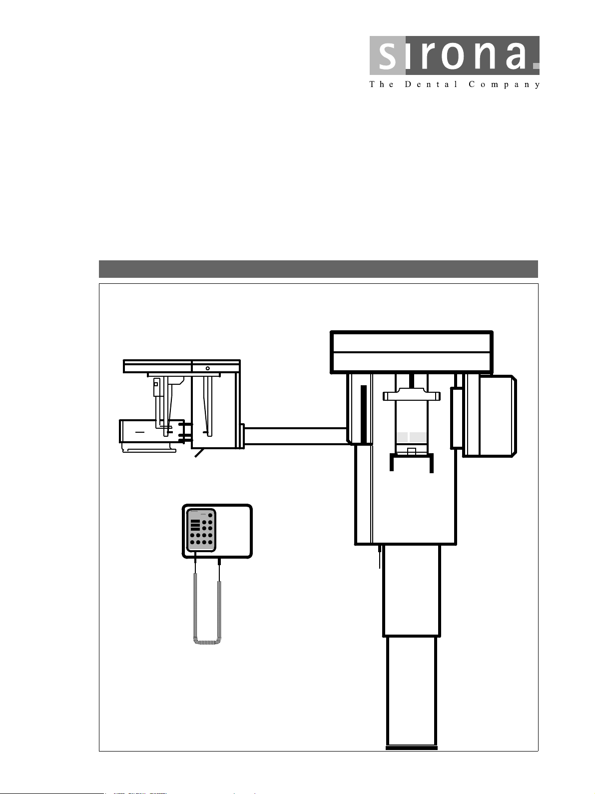
loqelmelp=mäìë=L=mäìë=`ÉéÜ
j~бенЙе~еЕЙ=fелнкмЕнбзел
Page 2

Maintenance Instructions Sirona Dental Systems GmbH
ATTENTION !
Proper shielding of room and operator position is
essential.
Since these requirements vary from state to state it is
the assembler's/installer's responsibility that all local
radiation safety requirements are met.
54 72 118 D 3297
2 D 3297.103.01.03.02
Page 3
Sirona Dental Systems GmbH Maintenance Instructions
General
To stay in compliance with the DHHS requirements the ORTHOPHOS® Plus / Plus Ceph must be maintained annually following date of installation.
It is the responsibility of the user to insure that the equipment is maintained with the manufacturer's recommended Maintenance Instructions to insure compliance with the Federal Performance Standard.
The manufacturer and the assembler/installer are relieved from responsibility in those cases where noncompliance with the standard results from the user's failure to have t he manufacturer's recommended maintenance performed.
The actual maintenance inspection and consequent service must be accomplished by a trained serviceman.
Neither the inspection nor service is part of the equipment warranty.
Technical instructions required
Operating Instructions
Service Manual
Instruments and adjustment tools required
1. Digital multimeter Philips PM 2816 rms, Fluke 8000 A, or equivalent.
Accuracy: DC voltage ± 0.1 % of reading plus 0.02% of range
DC current ± 0.4 % of reading plus 0.1% of range
2. Electromechanical pulse counter,
model KESSLER ELLIS KT 203 ±1 pulse, or equivalent.
3. Adjustment set with alignment tool for X-ray beam, test block, needle phantom delivered with the unit
(customer's property).
CAUTION RADIATION
Observe radiation protection guidelines as outlined in the Operating Instructions!
X-rays are generated, when the exposure button at the Multitimer is depressed.
Caution serviceman!
All PC-boards are fitted with electronic components sensitive to electrostat ic discharge (ESD).
Electrostatic charges are unavoidable due to friction of clothing, carp eting etc.
To prevent damage of electron ic components do not touch
same without putting on the unit mounted special wristlet.
Always handle circuit boards by the edge of same.
ESD
List of Contents Page
General 3
Visual Check 4
Light Indicators and Audible Sound 5 – 6
Power Supply Adequacy 7
kV-Verification 8 – 9
Tube Current Verification 10
Exposure Time Verification 11
Checking and Adjusting the X-Ray Beam for Panorama Exposure 12 – 13
Checking the AES 14 – 15
Phantom Radiograph 16
Checking the Ear Olives and Zero Position of Head Positioner 17
Checking the X-Ray Beam for Tele-Exposure 18
Yearly Maintenance Checklist appendix
54 72 118 D 3297
D 3297.103.01.03.02
3
Page 4
Maintenance Instructions Sirona Dental Systems GmbH
SIRONA
Model-No. 59 68 573 D 3200
Serial-No
lll 90kV 12mA DC
↓
2.5 Al / 80 IEC 522 1976
X-ray
head
Tube
By 257 / 82 Rö - Typ X 1426
Röhre / Tube
Siemens SR 90 / 15 FN
Model-No. 11 17 340 V 1010
Serial-No
0.5 IEC 336 / 82
MADE IN GERMANY
ModelNo.
SerialNo.
ModelNo.
SerialNo.
ModelNo.
SerialNo.
SIRONA
15 38 177 D 3200
SIRONA
46 80 364 D 3297
MADE IN GERMANY
Multitimer
SIRONA
14 48 450 D 3200
MADE IN GERMANY
Test block is part of
'Adjustment Set'
Test
block
X-RAY
For identification
turn wheel
clockwise.
Diaphragm 1
5 in. or 6 in.
Diaphragm 2
Diaphragm 3
10 in. or 8 in.
Diaphragm 4
Diaphragm 11
Model-No. 18 88 408 D3200
Serial-No.
Model-No. 18 88 382 D3200
Serial-No.
Model-No. 18 88 424 D3200
Serial-No.
Model-No. 18 88 366 D3200
Serial-No.
Model-No. 51 65 365 D3297
Serial-No.
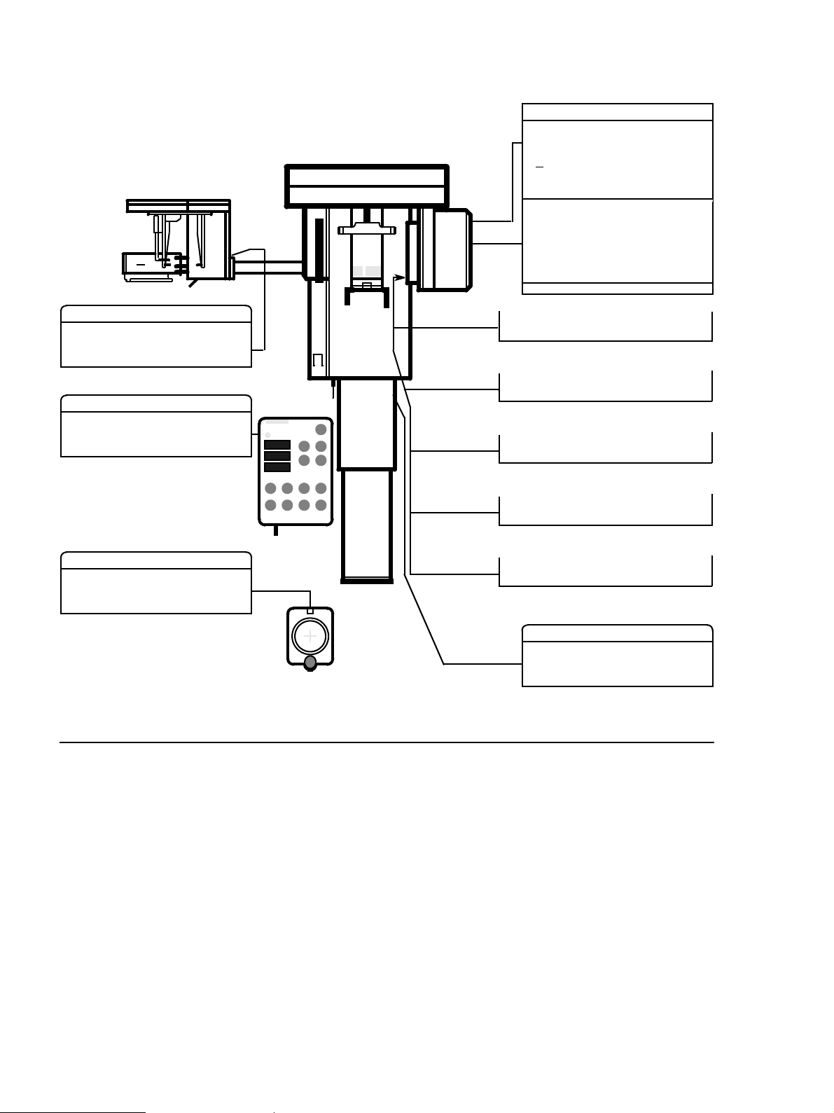
Unit
ModelNo.
SerialNo.
D 3297
MADE IN GERMANY
SIRONA
Visual Check
• Look for mechanical damage possibly affecting radiation safety.
• Verify that all labels are affixed and legible.
Defaced labels must be replaced.
Order same from Sirona (address, see rear)
in writing stating: Customer Name
Customer Address
All Model Numbers with Serial Numbers
still legible on the unit for identification purposes.
For serial numbers see also Installation Report / Warranty Passport.
54 72 118 D 3297
4 D 3297.103.01.03.02
Page 5
Sirona Dental Systems GmbH Maintenance Instructions
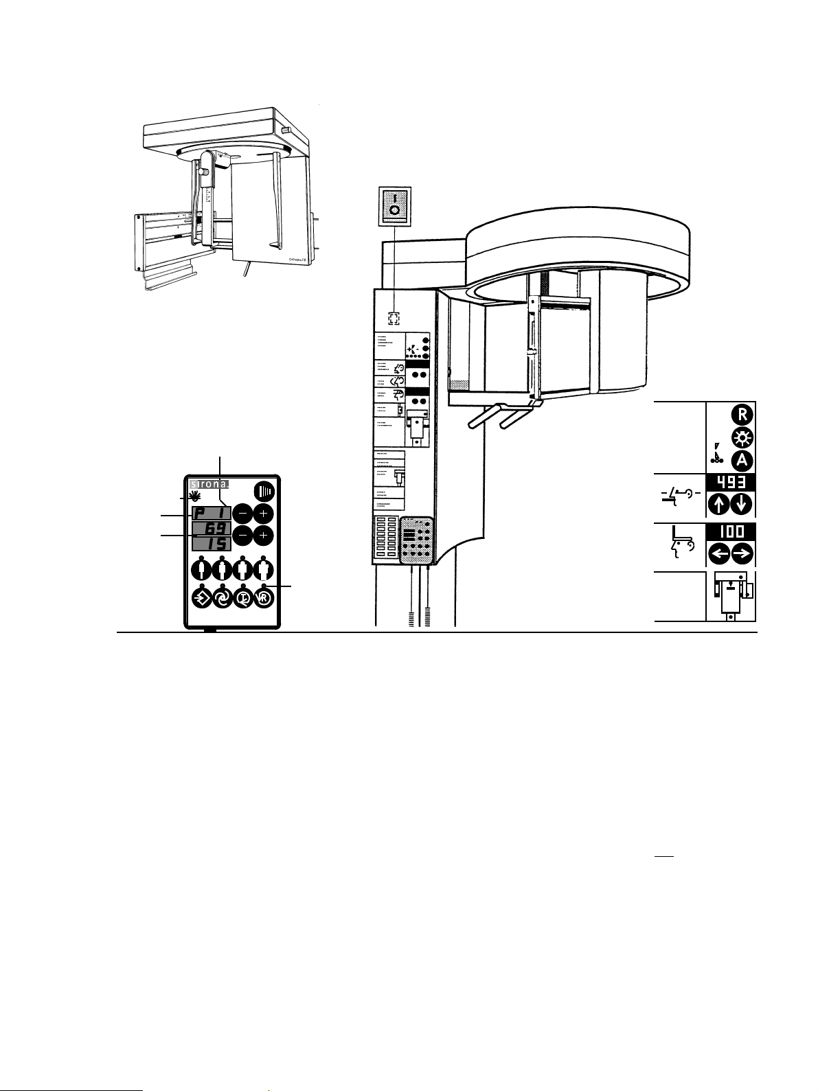
1.
C Ceph-mode
only
Unit ON LED
A
B
X-RAY
Ready LED
Multitimer
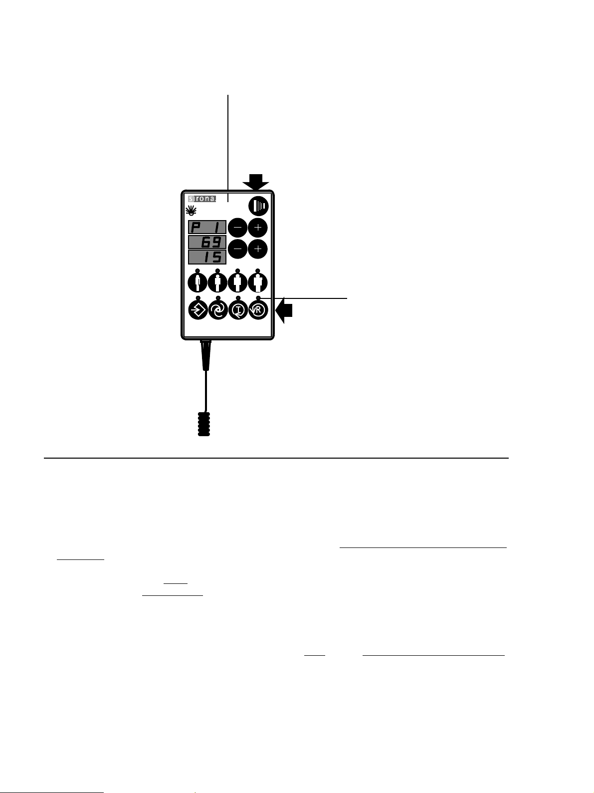
Light Indicators and Audible Sound at the Unit.
• Unit ON LED:
Depress the main switch (1) into the ”
The ”Unit ON LED” in the upper left corner of the Multitimer will then indicate that the unit is ON.
The unit adjusts itself automatically, wait about 1 minute.
• Digital displays at the Multitimer:
The program and exposure parameters employed with the last patient appear.
A shows you sequentially the P1 through P16 (P23) panoramic exposure programs and th e
respective maximum exposure time. Press – + pro gram bottons for correct display check.
B gives you the kV/mA matched value pair. The LED over the respective patient symbol must light up.
C C lights up, when Ceph–mode is selected.
Ready LED over the return button R must blink (When Ready LED blinks, unit is not
I” position.
ready).
+
V8 - V11
–
• Digital displays at the control panel:
- The mm value of height adjustment between 000 and 640 from t he last patient.
- The basic forehead support value of 10.0 mm.
- LED indication help messages
- Anomaly button LEDs
See also Operating Instructions under ”Preparing the Exposure” subchapter
”Switching ON the Unit”.
54 72 118 D 3297
D 3297.103.01.03.02
5
Page 6
Maintenance Instructions Sirona Dental Systems GmbH
Multitimer
Radiation
indication
X-ray
CAUTION RADIATION !
Observe
Radiation Protection Guide Lines
see Operating Instructions
Exposure
button
X-RAY
kV
mA
Ready LED
Return button R
• Make a panorama exposure: (Ceph–mode not selected)
- X-ray head must be in the initial position (Press return button R).
- Insert the panorama film cassette into the carriag e and swing in the cassette holder. The Ready LED
must go out. For more details and possible error messages see Operating Instructions.
- Set the P1 exposure program using the upper
- Select 69kV/15mA using the lower
– + buttons.
– + buttons.
- CAUTION RADIATION. Depress the exposure button and hold until the exposure terminates automatically
The exposure ends when rotation and radiation automatically switch off.
The radiation indication X-ray
Simultaneously an audible beep
• Interrupt an exposure
– deadman feature:
must light up during the exposure period.
must sound at the unit.
- Observe a cool-off time of 5 mins. between exposures (automatic exposure blockage).
- Setting same as above. Remove and reinsert the film cassette. The Ready LED must go out.
- CAUTION RADIATION. Depress the exposure button until
X-ray lights up and subsequently r elease
– the exposure must terminate immediately. The Ready LED blinks.
• Defective light indi cators con stitute a saf ety hazar d to the pati ent as well as to the operator. The
user is not permitted to use the unit, until repairs are made !
54 72 118 D 3297
6 D 3297.103.01.03.02
Page 7
Sirona Dental Systems GmbH Maintenance Instructions
1.
ON
door
metal cover
K1
N
L
3.
2.
300VAC
N
L
Terminal strip
main cable
5. – 8.
see Operating Instructions
4.
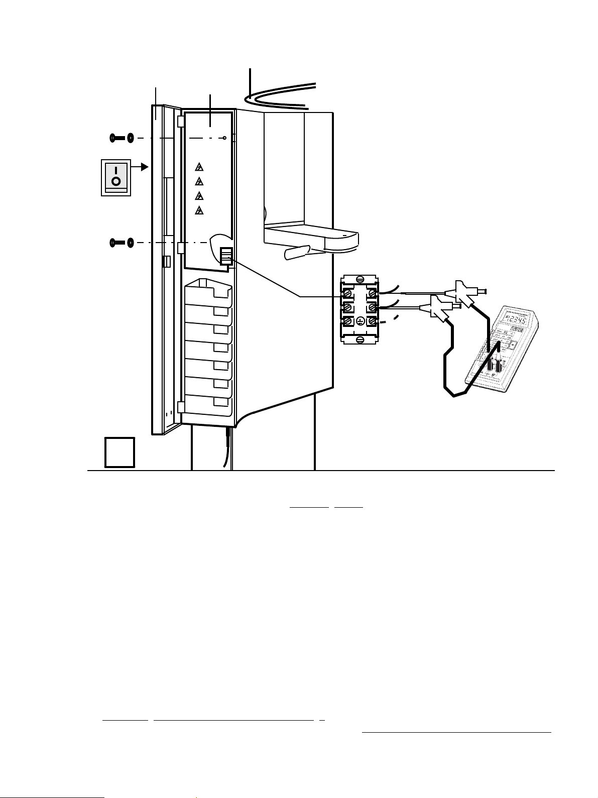
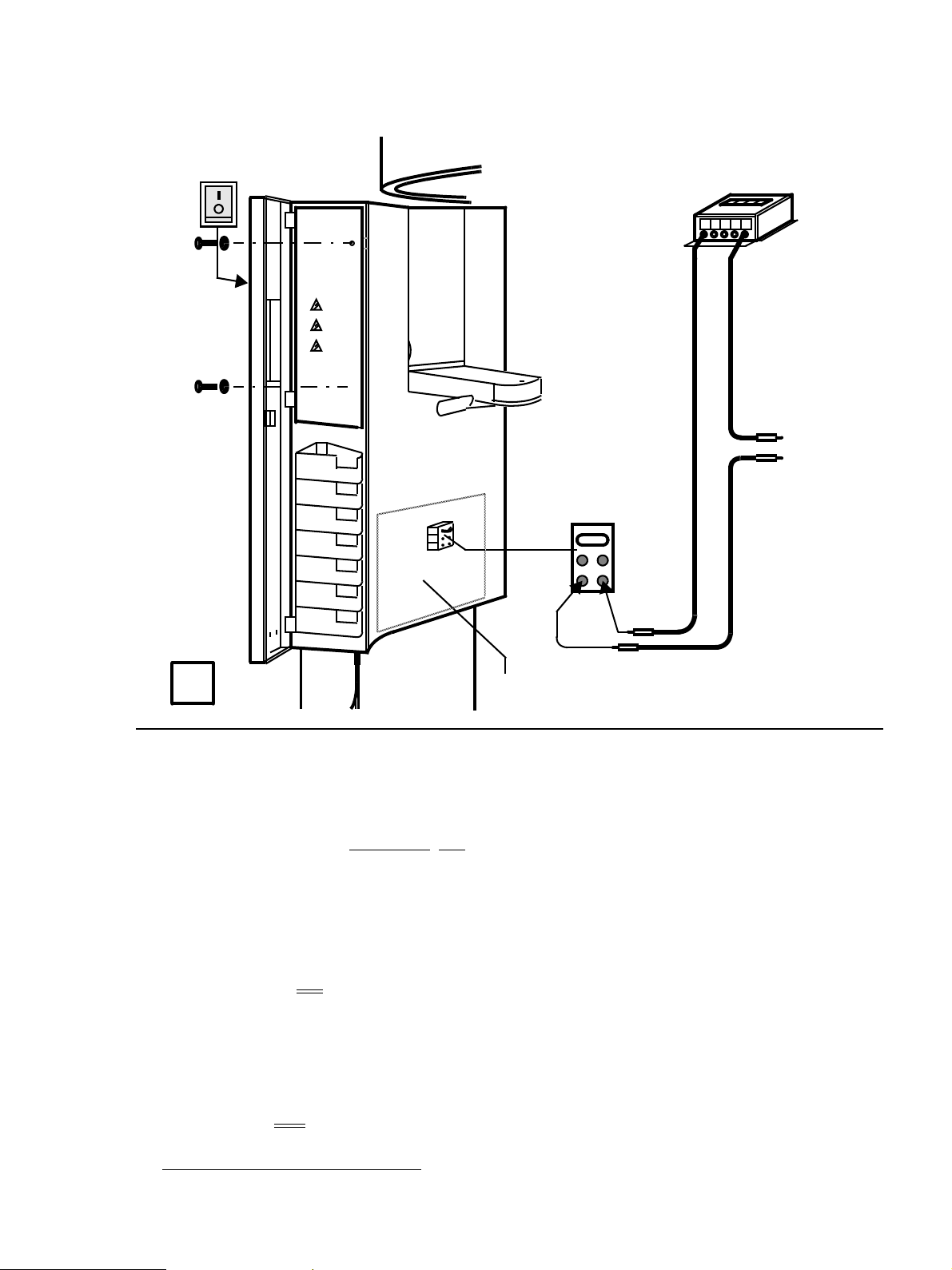
Power Supply Adequacy
• To determine power supply adequacy, the line voltage drop during exposure must be measured.
1. Be sure power cord is not plu gged in! Op en door and r emov e metal co ve r (2 scre ws) .
2. Select 300VAC line voltage range on multimeter.
3. Connect measuring leads to terminal K1, L and N.
4. Plug in power cord and switch unit ON, see Operating Instructions.
5. Press button R at the Multitimer to return X-ra y tube head into the initial p osition.
6. Remove and reinsert the film cassette.The Ready LED at the Multitimer must now go out.
7. Select P1 prog ram and 90kV/12mA at the Multitimer .
8. CAUTION RADIATION! - Depress the exposure button at the Multitimer until meter reading is obtained.
Line voltage Max. permissible
no load: 187 – 200V line voltage drop: 8V
201 – 220V 9V
221 – 240V 10V
241 – 264V 11V
•- - Record reading. Turn unit OFF and remove meter leads.
•If the volta
ply must be installed. Refer to Pre-I nstallation In structions. Disconn ect unit and do not release f or use!
54 72 118 D 3297
D 3297.103.01.03.02
ge drop is not within the specified range advise the customer, that an adequate power sup-
7
Page 8
Maintenance Instructions Sirona Dental Systems GmbH
3.
ON
1.
DX1
KV–
4. – 5.
2.
20VDC
com.
KV+
KV+
KV –
see Operating Instructions
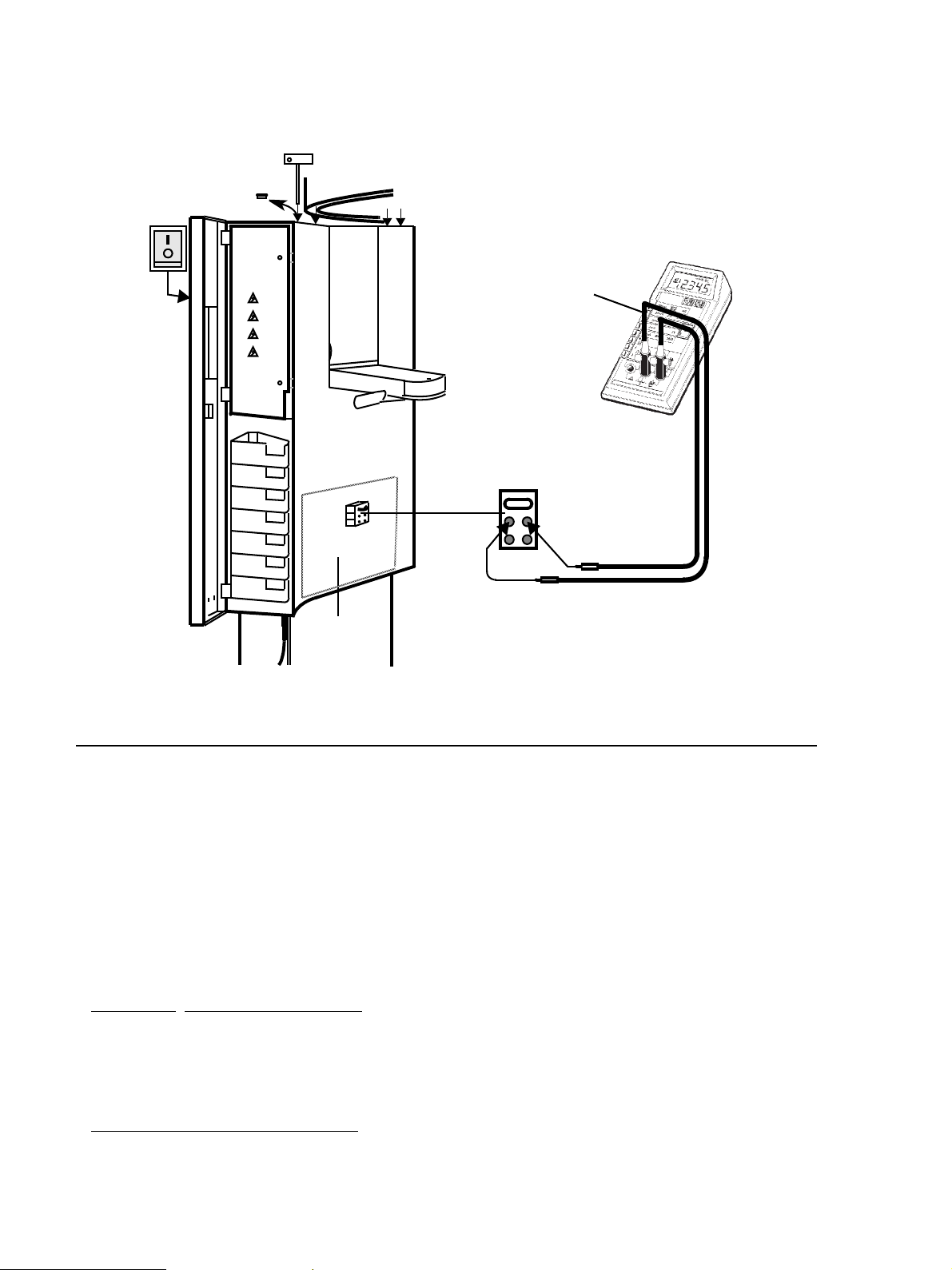
kV – Verification, kV–ramp during panoramic exposure
• During exposure the kV is encreased in the central region depending on kV/mA selected up to 17%.
This increase can be measured in VDC.
1. Remove covers . F or details see Service Manual.
2. Connect digital v oltmet er to KV+ and KV– a nd select range 20 VDC .
3. Switch unit ON. The X-ray head must be in the initial position (return button R),temple support fully
open.
4. Select P1 prog ram and 73kV/15mA at the Multit imer. Ready LED above button R must be out.
5. CA UTION RADIATION! - Depress the exposu re b utton until the e xposure terminates automatically.
• The followin
up to 5.25 seconds: 7.3 V ±0.4V,
from 6.25 to 7.85 s: 8.03 V ±0.1V,
after 8.85 seconds: 7.3 V±0.4V.
• Turn unit OFF and remove meter leads.
• If specified values cannot be obtained
Incorrect”
8 D 3297.103.01.03.02
g values must be obtained – see also diagram on next page.
, see Service Manual, ”Radiograph Density in Central Region
54 72 118 D 3297
Page 9
Sirona Dental Systems GmbH Maintenance Instructions
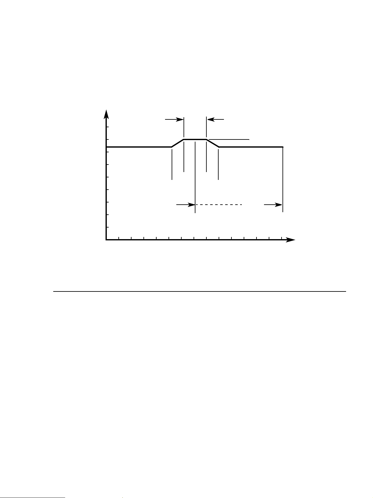
VDC
ramp
nominal 7.3V
9
8
7
max. 7.7V
min. 6.9V
1.6s
ramp
max. 8.1V
min. 7.9V
nominal 8.0V
6
5
4
3
7.05s
2
6.25 7.85
5.25s 8.85s
14.1s
complete P1
exposure time
1
1 104 5 6 7 8 9 11 12 13 143
kV – ramp diagram
with program P1 and 73kV/15mA set on the Multitimer and temple support fully open.
s exposure time0 2
54 72 118 D 3297
D 3297.103.01.03.02
9
Page 10

Maintenance Instructions Sirona Dental Systems GmbH
3.
ON
20mADC
2.
com.
1.
jumper
MA–
MA+
MA+
MA –
see Service Manual
DX1
4.
Tube Current Verification
1. Remove jump er from MA+/MA – test points .
2. Connect digital ammeter t o MA+ and MA– and select range 20 mADC .
3. Turn switch ON. Wait for self-adjustment of the unit.
4. Select service routine S.01.
• First measurement
- Select P1 program and 60kV/9mA at the Multitimer. The Ready LED must be out.
- CAUTION RADIATION! Depress the exposure button and hold depressed until meter reading
is obtained.
The multimeter shall indicate 9mA ±0.5mA. - - Record reading.
• Second measurement
- Select P1 program and 90kV/12mA at the Multitimer. The Ready LED must be out.
- CAUTION RADIATION! Depress the exposure button and hold depressed until meter reading
is obtained.
The multimeter shall indicate 12mA ±0.5mA. - - Record reading.
• Switch unit OFF. - Remove meter leads and replace jumper!
• If specified values cannot be obtained
10 D 3297.103.01.03.02
, see Service Manual, ”Checking theTube Current”
54 72 118 D 3297
Page 11
Sirona Dental Systems GmbH Maintenance Instructions
ON
Terminal strip
main cable
1.
3.
Pulse counter
com.
2.
To N
To L
of 110VAC/60Hz
power receptacle
T0T1
T0
T1
DX1
Exposure Time Verification for Panorama and Tele - Exposure
1. CAUTION! Switch the unit OFF. Switch off th e AC po wer at th e on-site cabinet.
2. Connect pulse counter according to t he connectio n diagr am abo v e .
3. Switch pow er ON and unit ON. W ait f or self-ad justment of the u nit. Mov e the X- ra y tube unit to the start
position (press the R ke y). Set diaphr a
• VERY IMPORTANT - Open temple support fully, see Operating Instructions.
• At the Multitimer: Select 73kV/15mA with P1 program for Panorama.
• CAUTION RADIATION !: Press the exposure key until the X-ray display switches off automatically
(complete rotation).
• The exposure time must be 14.1s±0.7s.
nominal 14.1 sec.=846
• For tele-exposure only: Prepare unit for tele-exposure, see Operating Instructions.
• At the Multitimer: Select 73kV/15mA with P1 program for Tele-Exposure.
• CAUTION RADIATION !: Press the exposure key until the X-ray display switches off automatically
(complete rotation).
• The exposure time must be 4s±0.2s.
nominal 4 sec.= 240
- - Record average pulse count. Switch unit OFF.
If specified value cannot be obtained
54 72 118 D 3297
D 3297.103.01.03.02
pulses±38 at 60Hz
pulses±10 at 60Hz
gm 1.
, see Service Manual ”Checking Exposure Times”.
11
Page 12

Maintenance Instructions Sirona Dental Systems GmbH
Beam
alignment
tool
ON
3.
2.
1.
X-RAY
4.
kV
mA
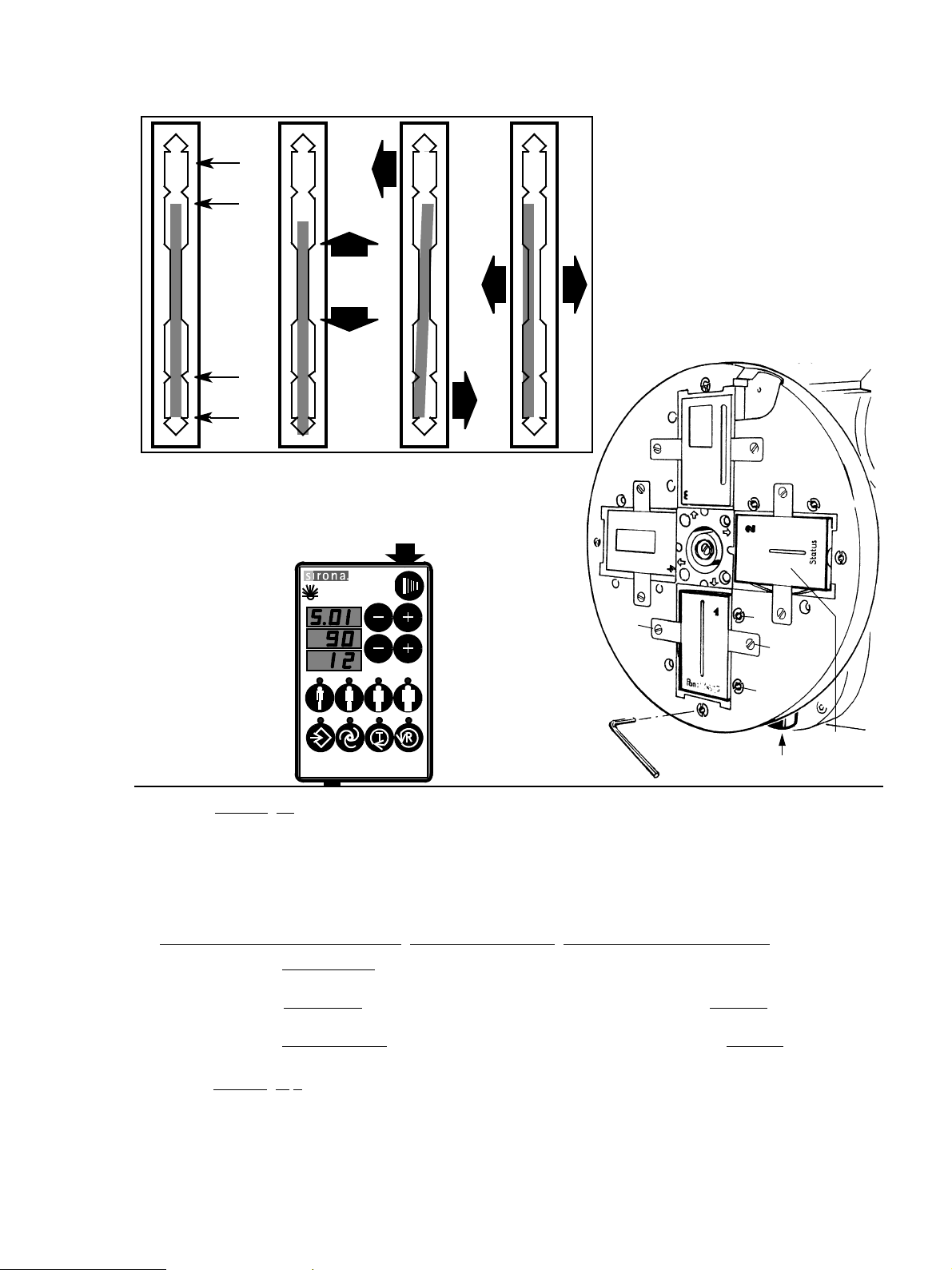
Checking and Adjusting the X-Ray Beam
1. Reattach metal front cover (4 screws with fan washers).
Reattach rear plastic cov er and plastic front cov er (engage below , affix with scre ws on the top and fit
cover caps).
2. Place beam alignment tool v ertically in the cassette carriage and mo v e behind t he slit co v er plat e.
3. Turn unit ON.
4. Select Service-Routine S.01 (see Service Manuel) and 90kV/12mA at the Multitimer .
54 72 118 D 3297
12 D 3297.103.01.03.02
Page 13
Sirona Dental Systems GmbH Maintenance Instructions
6”
5”
Film
height
Wheel
2 Status
1 Pan
Correct
position of
X-ray beam
5. Set the diaphragm 1 on the wheel into the position shown.
To move the wheel, press button D . X-radiation will only be activ ated when b utton D is engaged.
• Darken the room.
• Activate X-radiation to check correct position of X-ray beam. CAUTION RADIATION!
If X-ray beam is not in correct position a djust the X-r a y beam positi on to the correspon ding mark 1 of
the alignment tool. To do this activate X-radiation. CAUTION RADIATION!
Activate X-radiation only for as lon
X Beam correction 'HIGH – LOW': Loosen 2 screws E by 1 turn. Set beam via Allen screw A. Retigh ten
screws E.
Y Beam correction 'VERTICAL
screws E.
Z Beam correction 'RIGHT – LEFT
screws E.
6. Set the diaphra
With the same procedure as abov e adjust the X-ra y beam position to the corr esponding mark 2 of the
alignment tool.
X
RADIATION
X-RAY
kV
mA
': Loosen 2 screws E. Set beam via Allen screws B and C. Retighten
gm 2 on the wheel into the lower vertical position.
Y Z
g as you need to recognize the X-ray beam position.
': Loosen 2 screws E. Set beam via Allen screws B and C. Retighten
5.
C
E
B
6.
D
E
A
3mm
• Final check of X-ray beam position under ”Phantom Radiograph”.
54 72 118 D 3297
D 3297.103.01.03.02
13
Page 14

Maintenance Instructions Sirona Dental Systems GmbH
4.
Open fully
3.
Test block
1.
X-RAY
kV
mA
2.
5.
AES
Checking the AES, Automatic Exposure Selection
Enshure Fi Fo 20 is selected (see Operating Instruction)
1. Attach special test block
with adhesive tape. Chec k that it is e xactly v ertical.
2. Insert a loaded Orthophos film cassette until it locks in place, see Operating Instructions.
3. Remov e an y bite bl oc k from holder.
delivered as part of this unit (Adjustment set) t o bottom of slit cov er plate
Remove
4. Open
5. On the Multitimer:
14 D 3297.103.01.03.02
temple support fully! Turn knob countercloc kwise.
Select P1 program.
Press AES key.
Press patient symbol key on the right.
81kV/13mA is displayed.
54 72 118 D 3297
Page 15

Sirona Dental Systems GmbH Maintenance Instructions
8.
Film
density
Given AES
test values
X-RAY
kV
mA
RADIATION
X-RAY
kV
mA
6.
+
–
6. Adjust film density screw on Multitimer to 03, (mA-display) see also Opera ting Inst ructions,
chapter "Programming"
7. Prepare unit f or e xposure , see O perating Instructions .
7.
• Take a test block exposure
Keep exposure button depressed until rotation and radiation automatically switch off.
8. The kV/mA test value f or AES
• If given test values does not appear.
Carefully adjust the X-ray beam again, see chapter 'Checking and Adjusting the X-Ray Beam'.
• Take another test block exposure
• If given AES test values still does not appear, check the AES – see Service Manual, chapter
”Checking the AES”.
54 72 118 D 3297
D 3297.103.01.03.02
. CAUTION RADIATION!
given on the test block must appear in the displa y of t he Multitimer.
.
15
Page 16

Maintenance Instructions Sirona Dental Systems GmbH
4.
3.
Paper
Film
Paper
2.
1
1.
Process film
1
80mm±1mm
Line distance
a
2
6.
kV
mA
RADIATION
X-RAY
7.
Unexposed
margin
5.
a
8.
Phantom Radiograph
1. Fit the needle phantom up to stop.
2. Adjust primary diaphra
3. Cut out two paper strips as large as th e film siz e.
Place the film between the paper strips in the dark room
th bottom of cassette! (The paper strips are ne eded to neutr aliz e the intensi fying screens).
Attach film cassette to the unit's cassette ho lder (F or de tails see Oper ating Instructions).
gm 1 at the wheel.
– making sure film and paper strips are lev el wi-
a1=a2±0.5mm
4. Close
5. Select program P1 and lowest kV at the Multitimer.
6. CAUTION RADIATION! Initiate the exposu re f or a complete rotatin
7. Process the film.
8. Check the film: Measur e the
• If the distances exceed the above tolerances, act uators M2/M3 must be adjusted – see Service
16 D 3297.103.01.03.02
temple support fully! T urn knob cloc kwis e.
The X-ray head m ust be in st art position (Return button R)!
g cycle.
0
line distances on the film as shown.
NOTE: If distan ce is 88mm, temple support is open. Close temple support and make another e xposur e.
Manual.
l.......lllll .
80mm
54 72 118 D 3297
Page 17

Sirona Dental Systems GmbH Maintenance Instructions
1.
B
2.
X-RAY
kV
mA
RADIATION
5.
E
white cap
large ball
4.
3.
E
black cap
small ball
Checking the Ear Olives
• Metal balls in the adjustment caps E show up as dots on an exposed film. Both dots must coincide.
1. Prepare unit for tele-exposure (for details see Operating Instructions, steps 1. – 6.).
2. Pull out cassette holder to full extent and attach an intraoral film with adhesive tape.
3. Turn button B counter clockwise and position ear olives in X-ray path.
4. Pull out ear olive ho lders to maximum d istance and place adjust ing caps E on ear olives .
5. Select 62 kV/2.00 s on the Multitimer and release the exposure . RADIATION!
• Develop film to evaluate the position of the dots
• If the dots do not coincide see Installation Instructions, chapter 'Checking and Adjus ting the Ear
Olives' for correction.
.
54 72 118 D 3297
D 3297.103.01.03.02
17
Page 18
Maintenance Instructions Sirona Dental Systems GmbH
3.
2.
1.
1.
correct position
of X-ray beam
D
120
4. 1
4. 2
4.1
A 10x8
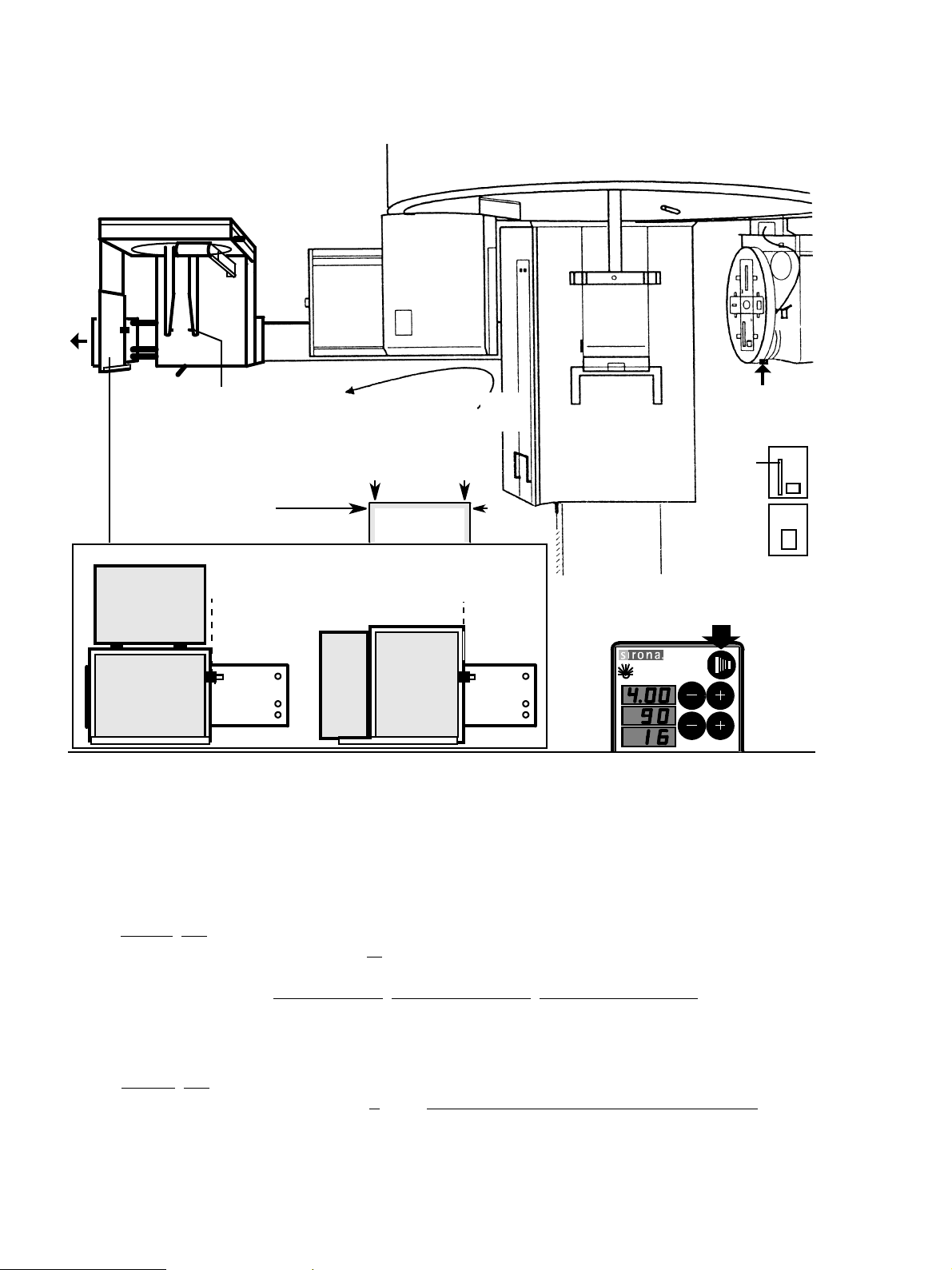
Checking the X-Ray Beam Positon for Tele – Exposure
1. Move the ear olive holder out of the X-ray beam path.
The cassette holder f or panor ama exposure is still out of the X-ray beam path .
2. Adjust cassette holder to full e xtent .
3. Head positioner must be in horizontal position, not tilt.
4. Two checks must be made: Se lect 90kV/4.00s at the Multitimer .
4.1 Chec k A=ASYMMETRICAL with diaphragm 3
Set diaphra
Engage lateral cassette holder at mark A
Insert opened cassette horizontally (for optional diaphragm 8x10: vertically) up to the stop.(Secure with adhesive tape).
Activate X-RADIATION — only for as long as you need to recogniz e the beam position.
• If the X-ray beam is not in the correct position, see Installation Instructions chapter 'Adjusting the X-
Ray Beam
4.2 Chec k S =SYMMETRICAL with diaphr agm 4
Set diaphra
Engage lateral cassette holder at mark S
Activate X-RADIATION to recognize the beam position.
• If the X-ray beam is not in the correct position, see Installation Instructions chapter 'Adjusting the X-
Ray Beam
gm 3 on wheel (press button D and turn wheel). Set soft-tissu e filter to position 120.
10x8. (For optional diaphr agm 8x10 in. engage at A 8x10).
for Tele – Exposure' for correction.
gm 4 on wheel.
8x10. Insert opened cassette vertically up to the stop.
for Tele – Exposure' for correction.
4.2
S 8x10
90kV/4s RADIATION
X-RAY
kV
mA
4.
3
4
54 72 118 D 3297
18 D 3297.103.01.03.02
Page 19

loqelmelp=mäìë=L=mäìë=`ÉéÜ
vЙ~кду=j~бенЙе~еЕЙ=`ЬЙЕвдблн
Customer: Address:
Dealer: Address:
Date of original installation: Date of inspection:
Report of Assembly FD 2579 #
SCHEDULE
All manuals are present
Test instruments as required
Manufacturer Model Accuracy Last calibrated
Voltmeter
mAmeter
Pulse counter
Any mechanical damage noticed
All labels are present and legible
All indicator lights are OK
Radiation indicator X-ray lights up, audible buzzer OK
Deadman feature OK
Power supply adequate
kV – Verification is OK
Yes No
Remarks
Line voltage: . . . . . . . . . .V
Voltage drop: . . . . . . . . . V
Tube current is within specified limits
Specified exposure time, panoramic (average pulses) OK
Specified exposure times, ceph (average pulses) OK
X-ray beam position, panoramic OK
X-ray beam position, ceph OK
Phantom radiograph, line distances within tolerance
The unit is in compliance with MFG specified tests and safety
1. Measurement: . . . . . . . mA
2. Measurement: . . . . . . . mA
Average pulse count: . . . . . .
Average pulse count: . . . . . .
Technician: Dealer:
54 72 118
D 3297.103.01.03.02 10.2004 54 72 118 D 3297
103.01.03
19
Page 20

loqelmelp=mäìë=L=mäìë=`ÉéÜ
vЙ~кду=j~бенЙе~еЕЙ=`ЬЙЕвдблн
Customer: Address:
Dealer: Address:
Date of original installation: Date of inspection:
Report of Assembly FD 2579 #
SCHEDULE
All manuals are present
Test instruments as required
Manufacturer Model Accuracy Last calibrated
Voltmeter
mAmeter
Pulse counter
Any mechanical damage noticed
All labels are present and legible
All indicator lights are OK
Radiation indicator X-ray lights up, audible buzzer OK
Deadman feature OK
Power supply adequate
kV – Verification is OK
Yes No
Remarks
Line voltage: . . . . . . . . . .V
Voltage drop: . . . . . . . . . V
Tube current is within specified limits
Specified exposure time, panoramic (average pulses) OK
Specified exposure times, ceph (average pulses) OK
X-ray beam position, panoramic OK
X-ray beam position, ceph OK
Phantom radiograph, line distances within tolerance
The unit is in compliance with MFG specified tests and safety
1. Measurement: . . . . . . . mA
2. Measurement: . . . . . . . mA
Average pulse count: . . . . . .
Average pulse count: . . . . . .
Technician: Dealer:
54 72 118
D 3297.103.01.03.02 10.2004 54 72 118 D 3297
103.01.03
20
Page 21

loqelmelp=mäìë=L=mäìë=`ÉéÜ
vЙ~кду=j~бенЙе~еЕЙ=`ЬЙЕвдблн
Customer: Address:
Dealer: Address:
Date of original installation: Date of inspection:
Report of Assembly FD 2579 #
SCHEDULE
All manuals are present
Test instruments as required
Manufacturer Model Accuracy Last calibrated
Voltmeter
mAmeter
Pulse counter
Any mechanical damage noticed
All labels are present and legible
All indicator lights are OK
Radiation indicator X-ray lights up, audible buzzer OK
Deadman feature OK
Power supply adequate
kV – Verification is OK
Yes No
Remarks
Line voltage: . . . . . . . . . .V
Voltage drop: . . . . . . . . . V
Tube current is within specified limits
Specified exposure time, panoramic (average pulses) OK
Specified exposure times, ceph (average pulses) OK
X-ray beam position, panoramic OK
X-ray beam position, ceph OK
Phantom radiograph, line distances within tolerance
The unit is in compliance with MFG specified tests and safety
1. Measurement: . . . . . . . mA
2. Measurement: . . . . . . . mA
Average pulse count: . . . . . .
Average pulse count: . . . . . .
Technician: Dealer:
54 72 118
D 3297.103.01.03.02 10.2004 54 72 118 D 3297
103.01.03
21
Page 22

loqelmelp=mäìë=L=mäìë=`ÉéÜ
vЙ~кду=j~бенЙе~еЕЙ=`ЬЙЕвдблн
Customer: Address:
Dealer: Address:
Date of original installation: Date of inspection:
Report of Assembly FD 2579 #
SCHEDULE
All manuals are present
Test instruments as required
Manufacturer Model Accuracy Last calibrated
Voltmeter
mAmeter
Pulse counter
Any mechanical damage noticed
All labels are present and legible
All indicator lights are OK
Radiation indicator X-ray lights up, audible buzzer OK
Deadman feature OK
Power supply adequate
kV – Verification is OK
Yes No
Remarks
Line voltage: . . . . . . . . . .V
Voltage drop: . . . . . . . . . V
Tube current is within specified limits
Specified exposure time, panoramic (average pulses) OK
Specified exposure times, ceph (average pulses) OK
X-ray beam position, panoramic OK
X-ray beam position, ceph OK
Phantom radiograph, line distances within tolerance
The unit is in compliance with MFG specified tests and safety
1. Measurement: . . . . . . . mA
2. Measurement: . . . . . . . mA
Average pulse count: . . . . . .
Average pulse count: . . . . . .
Technician: Dealer:
54 72 118
D 3297.103.01.03.02 10.2004 54 72 118 D 3297
103.01.03
22
Page 23

loqelmelp=mäìë=L=mäìë=`ÉéÜ
vЙ~кду=j~бенЙе~еЕЙ=`ЬЙЕвдблн
Customer: Address:
Dealer: Address:
Date of original installation: Date of inspection:
Report of Assembly FD 2579 #
SCHEDULE
All manuals are present
Test instruments as required
Manufacturer Model Accuracy Last calibrated
Voltmeter
mAmeter
Pulse counter
Any mechanical damage noticed
All labels are present and legible
All indicator lights are OK
Radiation indicator X-ray lights up, audible buzzer OK
Deadman feature OK
Power supply adequate
kV – Verification is OK
Yes No
Remarks
Line voltage: . . . . . . . . . .V
Voltage drop: . . . . . . . . . V
Tube current is within specified limits
Specified exposure time, panoramic (average pulses) OK
Specified exposure times, ceph (average pulses) OK
X-ray beam position, panoramic OK
X-ray beam position, ceph OK
Phantom radiograph, line distances within tolerance
The unit is in compliance with MFG specified tests and safety
1. Measurement: . . . . . . . mA
2. Measurement: . . . . . . . mA
Average pulse count: . . . . . .
Average pulse count: . . . . . .
Technician: Dealer:
54 72 118
D 3297.103.01.03.02 10.2004 54 72 118 D 3297
103.01.03
23
Page 24

loqelmelp=mäìë=L=mäìë=`ÉéÜ
vЙ~кду=j~бенЙе~еЕЙ=`ЬЙЕвдблн
Customer: Address:
Dealer: Address:
Date of original installation: Date of inspection:
Report of Assembly FD 2579 #
SCHEDULE
All manuals are present
Test instruments as required
Manufacturer Model Accuracy Last calibrated
Voltmeter
mAmeter
Pulse counter
Any mechanical damage noticed
All labels are present and legible
All indicator lights are OK
Radiation indicator X-ray lights up, audible buzzer OK
Deadman feature OK
Power supply adequate
kV – Verification is OK
Yes No
Remarks
Line voltage: . . . . . . . . . .V
Voltage drop: . . . . . . . . . V
Tube current is within specified limits
Specified exposure time, panoramic (average pulses) OK
Specified exposure times, ceph (average pulses) OK
X-ray beam position, panoramic OK
X-ray beam position, ceph OK
Phantom radiograph, line distances within tolerance
The unit is in compliance with MFG specified tests and safety
1. Measurement: . . . . . . . mA
2. Measurement: . . . . . . . mA
Average pulse count: . . . . . .
Average pulse count: . . . . . .
Technician: Dealer:
54 72 118
D 3297.103.01.03.02 10.2004 54 72 118 D 3297
103.01.03
24
Page 25

loqelmelp=mäìë=L=mäìë=`ÉéÜ
vЙ~кду=j~бенЙе~еЕЙ=`ЬЙЕвдблн
Customer: Address:
Dealer: Address:
Date of original installation: Date of inspection:
Report of Assembly FD 2579 #
SCHEDULE
All manuals are present
Test instruments as required
Manufacturer Model Accuracy Last calibrated
Voltmeter
mAmeter
Pulse counter
Any mechanical damage noticed
All labels are present and legible
All indicator lights are OK
Radiation indicator X-ray lights up, audible buzzer OK
Deadman feature OK
Power supply adequate
kV – Verification is OK
Yes No
Remarks
Line voltage: . . . . . . . . . .V
Voltage drop: . . . . . . . . . V
Tube current is within specified limits
Specified exposure time, panoramic (average pulses) OK
Specified exposure times, ceph (average pulses) OK
X-ray beam position, panoramic OK
X-ray beam position, ceph OK
Phantom radiograph, line distances within tolerance
The unit is in compliance with MFG specified tests and safety
1. Measurement: . . . . . . . mA
2. Measurement: . . . . . . . mA
Average pulse count: . . . . . .
Average pulse count: . . . . . .
Technician: Dealer:
54 72 118
D 3297.103.01.03.02 10.2004 54 72 118 D 3297
103.01.03
25
Page 26
loqelmelp=mäìë=L=mäìë=`ÉéÜ
vЙ~кду=j~бенЙе~еЕЙ=`ЬЙЕвдблн
Customer: Address:
Dealer: Address:
Date of original installation: Date of inspection:
Report of Assembly FD 2579 #
SCHEDULE
All manuals are present
Test instruments as required
Manufacturer Model Accuracy Last calibrated
Voltmeter
mAmeter
Pulse counter
Any mechanical damage noticed
All labels are present and legible
All indicator lights are OK
Radiation indicator X-ray lights up, audible buzzer OK
Deadman feature OK
Power supply adequate
kV – Verification is OK
Yes No
Remarks
Line voltage: . . . . . . . . . .V
Voltage drop: . . . . . . . . . V
Tube current is within specified limits
Specified exposure time, panoramic (average pulses) OK
Specified exposure times, ceph (average pulses) OK
X-ray beam position, panoramic OK
X-ray beam position, ceph OK
Phantom radiograph, line distances within tolerance
The unit is in compliance with MFG specified tests and safety
1. Measurement: . . . . . . . mA
2. Measurement: . . . . . . . mA
Average pulse count: . . . . . .
Average pulse count: . . . . . .
Technician: Dealer:
54 72 118
D 3297.103.01.03.02 10.2004 54 72 118 D 3297
103.01.03
26
Page 27

loqelmelp=mäìë=L=mäìë=`ÉéÜ
vЙ~кду=j~бенЙе~еЕЙ=`ЬЙЕвдблн
Customer: Address:
Dealer: Address:
Date of original installation: Date of inspection:
Report of Assembly FD 2579 #
SCHEDULE
All manuals are present
Test instruments as required
Manufacturer Model Accuracy Last calibrated
Voltmeter
mAmeter
Pulse counter
Any mechanical damage noticed
All labels are present and legible
All indicator lights are OK
Radiation indicator X-ray lights up, audible buzzer OK
Deadman feature OK
Power supply adequate
kV – Verification is OK
Yes No
Remarks
Line voltage: . . . . . . . . . .V
Voltage drop: . . . . . . . . . V
Tube current is within specified limits
Specified exposure time, panoramic (average pulses) OK
Specified exposure times, ceph (average pulses) OK
X-ray beam position, panoramic OK
X-ray beam position, ceph OK
Phantom radiograph, line distances within tolerance
The unit is in compliance with MFG specified tests and safety
1. Measurement: . . . . . . . mA
2. Measurement: . . . . . . . mA
Average pulse count: . . . . . .
Average pulse count: . . . . . .
Technician: Dealer:
54 72 118
D 3297.103.01.03.02 10.2004 54 72 118 D 3297
103.01.03
27
Page 28

loqelmelp=mäìë=L=mäìë=`ÉéÜ
vЙ~кду=j~бенЙе~еЕЙ=`ЬЙЕвдблн
Customer: Address:
Dealer: Address:
Date of original installation: Date of inspection:
Report of Assembly FD 2579 #
SCHEDULE
All manuals are present
Test instruments as required
Manufacturer Model Accuracy Last calibrated
Voltmeter
mAmeter
Pulse counter
Any mechanical damage noticed
All labels are present and legible
All indicator lights are OK
Radiation indicator X-ray lights up, audible buzzer OK
Deadman feature OK
Power supply adequate
kV – Verification is OK
Yes No
Remarks
Line voltage: . . . . . . . . . .V
Voltage drop: . . . . . . . . . V
Tube current is within specified limits
Specified exposure time, panoramic (average pulses) OK
Specified exposure times, ceph (average pulses) OK
X-ray beam position, panoramic OK
X-ray beam position, ceph OK
Phantom radiograph, line distances within tolerance
The unit is in compliance with MFG specified tests and safety
1. Measurement: . . . . . . . mA
2. Measurement: . . . . . . . mA
Average pulse count: . . . . . .
Average pulse count: . . . . . .
Technician: Dealer:
54 72 118
D 3297.103.01.03.02 10.2004 54 72 118 D 3297
103.01.03
28
Page 29

Page 30

tЙ=кЙлЙкоЙ=нЬЙ=кбЦЬн=нз=г~вЙ=~еу=~днЙк~нбзел=пЬбЕЬ=г~у=ДЙ=кЙимбкЙЗ=ЗмЙ=нз=нЙЕЬебЕ~д=бгйкзоЙгЙенлK
= pйк~ЕЬЙW=ЙеЦдблЕЬ= mкбенЙЗ=бе=dЙкг~еу
a=POVTKNMPKMNKMPKMO===NMKOMMQ ûKJkêKW= NMR=RUQ fгйкбг¨=Йе=^ддЙг~ЦеЙ
pбкзе~=aЙен~д=pулнЙгл=dгДe=
áå=íÜÉ=rp^W áå=`~å~Ç~W
c~Дкбвлнк~≈É=PN pбкзе~=aЙен~д=pулнЙгл=ii` pбкзе~=`~е~З~
aJSQSOR=_ЙелЬЙбг QUPR=páêçå~=aêáîÉI=pìáíÉ=NMM PORM=oбЗЦЙп~у=aкбоЙ=J=rебн=R lêÇÉê=kç
dÉêã~åó `Ь~кдзннЙI=k`=OUOTP jбллблл~мЦ~I=lен~кбз=iRi=RvS
пппKлбкзе~KЗЙ rp^ `~å~Ç~
RQ=TO=NNU=a=POVT
 Loading...