


Automation and Drives - SCE
Training Document
for Comprehensive Automation Solutions Totally Integrated Automation (T I A)
MODULE F6
Operator Control
with
WinCC flexible 2005 and
TP177B
T I A Training Document |
Page 1 of 129 |
Module |
|
|
F6 |
Issued: 02/2008 |
Operator Control |
with WinCC flexible 2005 |

Automation and Drives - SCE
This document has been written by Siemens AG for training purposes for the project entitled "Siemens Automation Cooperates with Education (SCE)".
Siemens AG accepts no responsibility for the correctness of the contents.
Transmission, use or reproduction of this document is only permitted within public training and educational facilities. Exceptions require the prior written approval by Siemens AG (Michael Knust michael.knust@siemens.com).
Offenders will be liable for damages. All rights, including the right to translate the document, are reserved, particularly if a patent is granted or utility model is registered.
We would like to thank the following: Michael Dziallas Engineering, the teachers at vocational schools, and all others who helped to prepare this document.
T I A Training Document |
Page 2 of 129 |
Module |
|
|
F6 |
Issued: 02/2008 |
Operator Control |
with WinCC flexible 2005 |

Automation and Drives - SCE
1. |
PREFACE..................................................................................................................................................... |
6 |
|
2. |
OPERATOR CONTROL WITH WINCC FLEXIBLE .................................................................................... |
8 |
|
2.1 |
SYSTEM DESCRIPTION ................................................................................................................................. |
8 |
|
2.2 |
INSTALLATION/DEINSTALLATION ................................................................................................................... |
9 |
|
2.2.1 |
System Prerequisites......................................................................................................................... |
9 |
|
2.2.2 |
Installing WinCC flexible .................................................................................................................. |
10 |
|
2.2.3 |
Deinstalling WinCC flexible ............................................................................................................. |
10 |
|
2.2.4 |
Totally Integrated Automation.......................................................................................................... |
11 |
|
3. |
PROJECT DESCRIPTION ......................................................................................................................... |
12 |
|
3.1 |
HARDWARE CONFIGURATION ..................................................................................................................... |
12 |
|
3.2 |
PLANT DESCRIPTION ................................................................................................................................. |
13 |
|
3.3 |
TASK DEFINITION....................................................................................................................................... |
14 |
|
3.4 |
CONFIGURATION........................................................................................................................................ |
14 |
|
4 STEP7 PROJECT "COLOR MIXING PLANT“ ............................................................................................. |
15 |
||
4.1 |
NEW PROJECT .......................................................................................................................................... |
15 |
|
4.2 |
HARDWARE CONFIGURATION ..................................................................................................................... |
17 |
|
4.3 |
LIBRARY OF THE COLOR MIXING PLANT ...................................................................................................... |
18 |
|
4.4 |
ASSIGNMENT LIST ..................................................................................................................................... |
20 |
|
4.5 |
CONTROL PROGRAM ................................................................................................................................. |
21 |
|
4.5.1 |
Function Block FB1.......................................................................................................................... |
21 |
|
4.5.2 |
Variable Declaration ........................................................................................................................ |
22 |
|
4.5.3 Inserting Panel Inputs FB5 as Multi Instance Block from the Program Library............................... |
23 |
||
4.5.4 |
Tank Block FB10 ............................................................................................................................. |
26 |
|
4.5.5 Automatic Program Sequence FB15 ............................................................................................... |
29 |
||
4.5.6 |
Manual Operation FC20 .................................................................................................................. |
30 |
|
4.5.7 |
Mixer Motion FB25........................................................................................................................... |
31 |
|
4.5.8 Automatic and Manual Lamps ......................................................................................................... |
31 |
||
4.5.9 |
Organization Block OB1 .................................................................................................................. |
32 |
|
4.6 |
LOADING TO THE CPU ............................................................................................................................... |
33 |
|
4.7 |
PROGRAM TEST ........................................................................................................................................ |
33 |
|
5 SIMATIC HMI STATION ................................................................................................................................ |
34 |
||
5.1 |
INSERTING AN HMI STATION ...................................................................................................................... |
34 |
|
5.2 |
CONFIGURING THE HMI STATION ............................................................................................................... |
36 |
|
5.3 |
CHECKING THE CONNECTION WITH NETPRO ............................................................................................... |
37 |
|
5.4 |
OPENING THE HMI STATION....................................................................................................................... |
38 |
|
6 WINCC FLEXIBLE ENGINEERING SYSTEM .............................................................................................. |
39 |
||
6.1 |
PROGRAM INTERFACE................................................................................................................................ |
39 |
|
6.1.1 Menus and Symbol Bars.................................................................................................................. |
40 |
||
6.1.2 |
Work Space ..................................................................................................................................... |
41 |
|
6.1.3 |
Project Window................................................................................................................................ |
42 |
|
6.1.4 |
Property Window ............................................................................................................................. |
43 |
|
T I A Training Document |
Page 3 of 129 |
Module |
|
|
F6 |
Issued: 02/2008 |
Operator Control |
with WinCC flexible 2005 |

|
|
|
|
|
|
|
|
|
|
|
|
Automation and Drives - SCE |
|
|
|
|
|
|
|
|
|
|
|
|
|
||
|
|
|
|
|
|
|
|
|
|||||
|
|
|
|
|
|
|
|
|
|
|
|||
|
|
|
|
||||||||||
6.1.5 |
Tool Window .................................................................................................................................... |
44 |
|||||||||||
6.1.6 |
Output Window ................................................................................................................................ |
45 |
|||||||||||
6.1.7 |
Object Window................................................................................................................................. |
45 |
|||||||||||
6.1.8 |
Resetting the Arrangement.............................................................................................................. |
45 |
|||||||||||
6.2 |
|
|
|
CONFIGURING DISPLAYS............................................................................................................................ |
46 |
||||||||
6.2.1 |
Display Template ............................................................................................................................. |
47 |
|||||||||||
6.2.2 |
Generating Displays ........................................................................................................................ |
51 |
|||||||||||
6.2.3 |
Inserting Graphic Displays............................................................................................................... |
52 |
|||||||||||
6.2.4 |
Configuring Display Changes .......................................................................................................... |
55 |
|||||||||||
6.3 |
|
|
|
SETTINGS AT THE TOUCH PANEL TP177B COLOR PN/DP ........................................................................... |
58 |
||||||||
|
|
6.3.1 Setting the Date and the Time of Day ............................................................................................. |
59 |
||||||||||
|
|
6.3.2 Setting the MPI Address .................................................................................................................. |
60 |
||||||||||
|
|
6.3.3 Setting the Profibus DP Address ..................................................................................................... |
61 |
||||||||||
|
|
6.3.4 Assigning the Ethernet Address ...................................................................................................... |
61 |
||||||||||
|
|
6.3.5 Setting the Transfer Properties........................................................................................................ |
62 |
||||||||||
6.3.6 |
Transfer Mode ................................................................................................................................. |
62 |
|||||||||||
6.4 |
|
|
|
CHECKING FOR CONSISTENCY ................................................................................................................... |
63 |
||||||||
6.5 |
|
|
|
TRANSFER SETTINGS AND DATA TRANSFER UNDER WINCC FLEXIBLE .......................................................... |
63 |
||||||||
6.6 |
|
|
|
BUTTON END ........................................................................................................................................... |
65 |
||||||||
6.7 |
|
|
|
CONFIGURING A CONNECTION.................................................................................................................... |
67 |
||||||||
7 DISPLAY AND OPERATOR OBJECTS ....................................................................................................... |
68 |
||||||||||||
7.1 |
|
|
|
LEVELS ..................................................................................................................................................... |
68 |
||||||||
7.2 |
|
|
|
BASIC OBJECTS ........................................................................................................................................ |
69 |
||||||||
7.3 |
|
|
|
EXPANDED OBJECTS ................................................................................................................................. |
71 |
||||||||
8 DISPLAY AND OPERATOR OBJECTS IN THE PROJECT "COLOR MIXING PLANT“............................ |
72 |
||||||||||||
8.1 |
|
|
|
CONFIGURING DISPLAY AND OPERATOR OBJECTS IN THE PICTURE“TANK1“.................................................. |
72 |
||||||||
|
|
8.1.1 Configuring the Bar Display............................................................................................................. |
72 |
||||||||||
|
|
8.1.2 Configuring the Linear Regulator..................................................................................................... |
76 |
||||||||||
8.1.3 |
Configuring a Button ........................................................................................................................ |
79 |
|||||||||||
|
|
8.1.4 Representing the Valve Function in Color....................................................................................... |
83 |
||||||||||
|
|
8.1.5 Testing the Picture “Tank1“ in Runtime........................................................................................... |
86 |
||||||||||
8.2 |
|
|
|
CONFIGURING THE DISPLAY AND OPERATOR OBJECTS IN THE PICTURES “TANK2“ AND “TANK3“.................... |
87 |
||||||||
8.3 |
|
|
|
OBJECTS IN THE BASIC DISPLAY................................................................................................................. |
89 |
||||||||
|
|
8.3.1 Tank Levels and Valve Representations......................................................................................... |
89 |
||||||||||
|
|
8.3.2 Configuring the Mixer Motor ............................................................................................................ |
90 |
||||||||||
8.3.3 |
Configuring the Manual Mode for the Outflow Valve of the Container ........................................... |
95 |
|||||||||||
8.3.4 |
Switching Operating Modes............................................................................................................. |
97 |
|||||||||||
|
|
8.3.5 Configuring the Fill Entries............................................................................................................... |
99 |
||||||||||
|
|
8.3.6 Configuring the “START“ Button.................................................................................................... |
101 |
||||||||||
|
|
8.3.7 Configuring the Mixer Motion......................................................................................................... |
103 |
||||||||||
8.4 |
|
|
|
CONFIGURING OBJECTS IN THE PERMANENT WINDOW............................................................................... |
107 |
||||||||
8.4.1 |
Configuring Text Fields.................................................................................................................. |
107 |
|||||||||||
|
|
8.4.2 Configuring the Output Fields........................................................................................................ |
108 |
||||||||||
9 CONFIGURING MESSAGES ...................................................................................................................... |
111 |
||||||||||||
9.1 |
|
|
|
ANALOG MESSAGES ................................................................................................................................ |
111 |
||||||||
T I A Training Document |
Page 4 of 129 |
Module |
|
|
F6 |
Issued: 02/2008 |
Operator Control |
with WinCC flexible 2005 |

|
|
|
|
|
|
|
|
|
|
|
|
|
Automation and Drives - SCE |
|
|
|
|
|
|
|
|
|
|
|
|
|
|
|
|
|
|
|
|
|
|
|
|
|
|
|
|
|
|
|
|
|
|
|
|
|
|
|
|
|
|
|
|
|
|
|
|
|
|||||||
9.2 |
|
|
|
BIT MESSAGES........................................................................................................................................ |
111 |
||||||||
9.3 |
|
|
|
MESSAGE WINDOW ................................................................................................................................. |
112 |
||||||||
9.4 |
|
|
|
MESSAGE INDICATOR .............................................................................................................................. |
114 |
||||||||
|
9.5 TESTING THE MESSAGE CONFIGURATION IN RUNTIME ............................................................................... |
115 |
|||||||||||
10 |
|
|
|
CONFIGURING RECIPES ....................................................................................................................... |
116 |
||||||||
10.1 |
|
|
|
ADDING RECIPES ................................................................................................................................. |
116 |
||||||||
10.2 |
|
|
|
SPECIFYING DATA SETS....................................................................................................................... |
117 |
||||||||
10.3 |
|
|
|
GENERATING THE PICTURES “RECIPE INPUT“ AND “RECIPE SELECTION“ ................................................. |
117 |
||||||||
10.3.1 |
Configuring the Picture “Recipe Input“ .......................................................................................... |
117 |
|||||||||||
10.3.2 |
Configuring the picture "Recipe Selection“.................................................................................... |
119 |
|||||||||||
10.3.3 |
Configuring Buttons for Display Change ....................................................................................... |
120 |
|||||||||||
10.4 |
|
|
|
SELECTING RECIPES IN RUNTIME.......................................................................................................... |
122 |
||||||||
10.5 |
|
|
|
Entering New Recipes in Runtime................................................................................................. |
123 |
||||||||
11 |
|
|
|
CONFIGURING USER MANAGEMENT.................................................................................................. |
124 |
||||||||
11.1 |
|
|
|
SETTING UP THE USER GROUP ............................................................................................................. |
124 |
||||||||
11.2 |
|
|
|
SETTING UP USERS ............................................................................................................................. |
125 |
||||||||
11.3 |
|
|
|
ASSIGNING AUTHORIZATIONS ............................................................................................................... |
126 |
||||||||
11.3.1 |
Protecting the Start Button............................................................................................................. |
126 |
|||||||||||
11.3.2 |
Protecting Data Selection .............................................................................................................. |
127 |
|||||||||||
11.3.3 |
Protecting Recipe Input ................................................................................................................. |
127 |
|||||||||||
11.3.4 |
Protecting the Operating Mode Selection...................................................................................... |
128 |
|||||||||||
11.4 |
|
|
|
TESTING USER MANAGEMENT IN RUNTIME ............................................................................................ |
129 |
||||||||
The following symbols are provided as a guide through Module F6:
Information
Installation
Programming
Sample Exercise
Notes
T I A Training Document |
Page 5 of 129 |
Module |
|
|
F6 |
Issued: 02/2008 |
Operator Control |
with WinCC flexible 2005 |
Automation and Drives - SCE
PREFACE
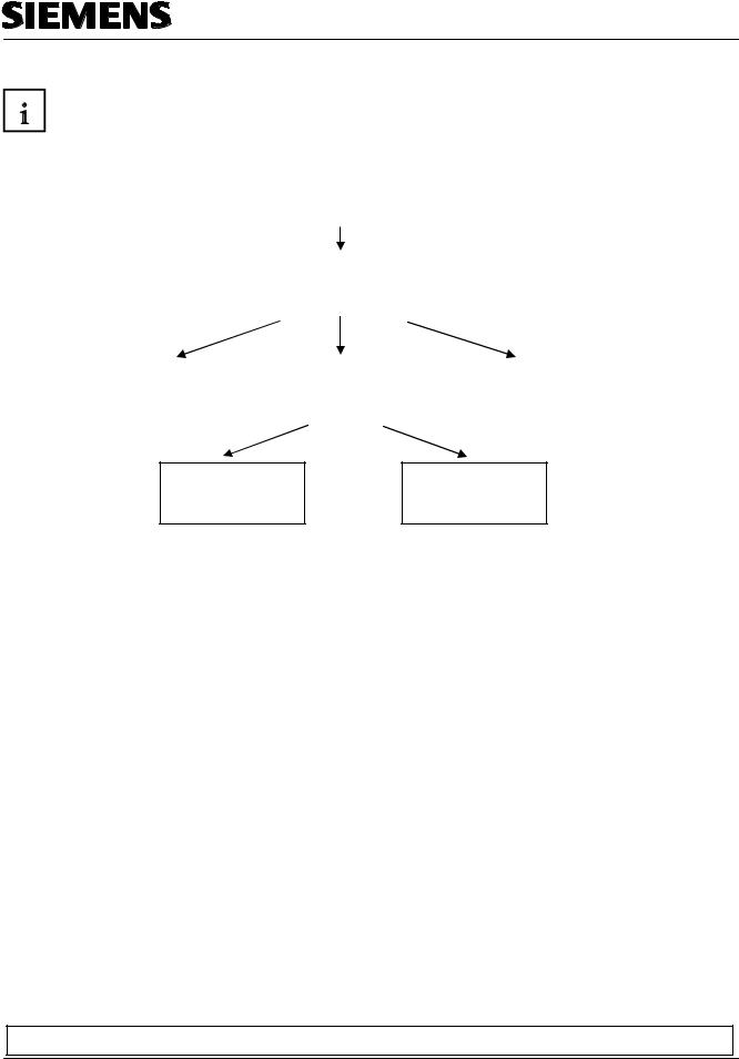
In terms of its contents, Module F6 is part of the teaching unit entitled 'Process Visualization’.
|
|
|
Fundamentals of |
|
|
|
||
|
|
|
STEP7 Programming |
|
|
|
||
|
|
2 to 3 days |
Modules A |
|
|
|
||
|
|
|
|
|
|
|
|
|
|
|
|
|
|
|
|||
|
|
Additional Functions of |
|
|
|
|||
|
|
|
Plant Simulation with |
|||||
|
|
|
STEP7 Programming |
|
||||
|
|
|
|
SIMIT SCE |
||||
|
|
|
2 to 3 days |
Modules B |
|
|||
|
|
|
|
1 to 2 days Modules G |
||||
|
|
|
|
|
|
|
||
|
|
|
|
|
|
|||
|
|
|
|
|
|
|
|
|
|
|
|
|
|
|
|
|
|
Programming |
|
|
Industrial Fieldbus |
|
Process |
|
||
Languages |
|
|
Systems |
|
|
Visualization |
|
|
2 to 3 days Modules C |
|
|
2 to 3 days |
Modules |
|
2 to 3 days Modules |
|
|
Frequency Converter on SIMATIC S7
2 to 3 days Modules
IT Communication wirh SIMATIC S7
2 to 3 days Modules E
Learning Objective:
In Module F6, the reader is introduced to the essential functions of the software WinCC flexible 2005.
Typical task definitions are processed using a sample system.
•Installing the software
•Steps for generating a Step7 project
•Inserting an HMI station
•Interface of WinCC flexible
•Configuring display and operator objects
•Configuring messages
•Generating recipe management
•Setting up user management
Prerequisites:
•Knowledge in handling Windows
•Fundamentals of PLC programming with STEP 7 (for example, Module A3 - 'Startup’ PLC Programming with STEP 7)
Preface Installation Project Description Step7 Project HMI Station WinCC flexible Project Messages Recipes User Management
T I A Training Document |
Page 6 of 129 |
Module |
|
|
F6 |
Issued: 02/2008 |
|
Operator Control with WinCC flexible 2005 |

Automation and Drives - SCE
Hardware and software required
1 PC, operating system Windows 2000 SP4 or Windows XP Professional SP1 and SP2 with MS Internet Explorer V6.0 SP1
Pentium IV with 1.6 GHz, 512MB RAM, approx. 1.5GB free hard disk storage 2 Software STEP7 V 5.4
3 Configuring software WinCC flexible 2005 Advanced
4 MPI interface for the PC (for example, PC Adapter USB) 5 Sample configuration for PLC SIMATIC S7-300:
- Power supply: PS 307 2A - CPU: CPU 314
- Digital inputs: DI 16x DC 24V
- Digital outputs: DO 16x DC 24V/0.5A 6 Touch Panel TP177B
7 MPI or Profibus DP data cable for connecting the TP177B to the controller
1 PC
2 STEP7 V5.3


 4 PC Adapter
3 Configuring Software WinCC flexible 2005 Advanced
5 SIMATIC S7-300 |
7 MPI or Profibus DP |
|
|
Data Cable |
6 Touch Panel TP177B |
||
|
Preface Installation Project Description Step7 Project HMI Station WinCC flexible Project Messages Recipes User Management
T I A Training Document |
Page 7 of 129 |
Module |
|
|
F6 |
Issued: 02/2008 |
|
Operator Control with WinCC flexible 2005 |

Automation and Drives - SCE
2.OPERATOR CONTROL WITH WINCC FLEXIBLE
2.1System Description
Since processes are becoming more and more multi-layered and the demands on the functionality of machines and plants are increasing, the operator needs a high-performance tool for controlling and monitoring production plants. An HMI system (Human Machine Interface) represents the interface between a human being (the operator) and the process (machine/plant). The controller actually controls the process. That is, there are two interfaces: one between the operator and WinCC flexible (at the operator panel), and another interface between WinCC flexible and the controller.
The WinCC flexible Engineering System is the software that is used to handle all required configuring tasks. The WinCC flexible Edition determines which operator panels of the SIMATIC HMI spectrum can be configured.
WinCC flexible Runtime is the software for process visualization. In runtime, the project is executed in the process mode.
WinCC flexible performs the following tasks:
• Displaying the process
The process is mapped to the operator panel. If a status changes in the process, for example, the display at the operator panel is updated.
• Operating the process
The operator can operate the process by means of the graphic operator interface. For example, the operator can specify a setpoint for the controller, or start a motor.
• Reading out messages
If critical process states occur in the process, a message is triggered automatically; for example, if the specified limit is exceeded.
• Archiving process values and messages
The HMI system can archive messages and process values. In this way, you can document the process characteristics, and you can also access older production data later.
• Documenting process values and messages
The HMI system can read out messages and process values as protocol. Thus, you can have production data read out after the end of a shift, for example.
• Managing process parameters and machine parameters
The HMI system can store parameters for processes and machines in recipes. With one operational step, you can transfer these parameters from the operator panel to the controller, in order to change production to another product variant.
Preface Installation Project Description Step7 Project HMI Station WinCC flexible Project Messages Recipes User Management
T I A Training Document |
Page 8 of 129 |
Module |
|
|
F6 |
Issued: 02/2008 |
|
Operator Control with WinCC flexible 2005 |

Automation and Drives - SCE
2.2Installation/Deinstallation
2.2.1System Prerequisites
WinCC flexible supports all common PC platforms that are IBM/AT compatible. Although values for a minimum configuration are specified, you should use as a guide the recommended values for an optimum configuration, for WinCC flexible to operate efficiently.
System Prerequisites for |
WinCC flexible ES |
|
|
Operating System |
Windows 2000 SP4, Windows XP Professional |
|
SP1 and SP2 |
|
|
|
For multi-lingual configurations: Windows 2000 |
|
SP4 MUI, Windows XP Professional SP1 and |
|
SP2 MUI |
|
|
Processor |
|
|
|
• Minimum |
Pentium 4 |
|
|
• Recommended |
≥ Pentium 4, 2.0 GHz |
|
|
Resolution |
|
|
|
• Minimum |
1024 x 768 |
|
|
• Recommended |
≥ 1280 x 1024 |
|
|
RAM |
|
|
|
• Minimum |
512 Mbyte |
|
|
• Recommended |
≥ 1 Gbyte, ≥ 512 Mbyte for WinCC flexible |
|
micro |
|
|
Hard disk drive (free |
≥ 1 Gbyte |
memory) 1) |
|
Diskette drive 2) |
3.5“/1.44 Mbyte |
|
|
CD-ROM |
for software installation |
|
|
1) In addition to WinCC flexible, Windows also makes demands on the free hard disk drive capacity.
For example, free memory should be provided for the swap out file. The following formula has proven successful: Size of swap out file = 3 times the size of the RAM.
Additional information is provided in the Windows documentation 2) To transfer the License Key
Preface Installation Project Description Step7 Project HMI Station WinCC flexible Project Messages Recipes User Management
T I A Training Document |
Page 9 of 129 |
Module |
|
|
F6 |
Issued: 02/2008 |
|
Operator Control with WinCC flexible 2005 |
Automation and Drives - SCE
2.2.2Installing WinCC flexible
After all system requirements that have been mentioned are met, install WinCC flexible from the CDROM. Select the scope for installing components and product languages.
•Standard installation: recommended
•Minimum installation: to save memory
•User defined installation: to specify yourself which components and product languages are installed
In addition, the required licenses have to be transferred. You can install the licenses along with the components and product languages, or you can install them subsequently. If you have obtained WinCC flexible options, install each option separately. An option is installed by loading the associated license key.
Detailed information regarding the installation are provided in the Installation Instructions on the CDROM 'WinCC flexible Software CD1’ in the folder "Documents\<Language>\Installation Guides“.
2.2.3Deinstalling WinCC flexible
Close all applications that are open, particularly the WinCC flexible Engineering System and WinCC flexible Runtime. Deactivate WinCC flexible Smart Start.
Additional notes on WinCC flexible Smart Start are provided in the chapter "WinCC flexible Smart Start".
Open the system control by means of "Start ► Settings ► System Control".
In the system control, double click on the entry "Software". The dialog "Software" is opened.
In the dialog "Software", select the entry "SIMATIC WinCC flexible 2005". The button "Change/remove" is displayed.
Click on the button "Change/Remove". The WinCC flexible InstallShield Wizard is opened. Activate the option "Remove program" and click on the button "Continue".
Confirm the deinstallation with "OK". WinCC flexible is removed from the configuring computer. In the dialog that follows, close the deinstallation with the button "Complete".
Preface Installation Project Description Step7 Project HMI Station WinCC flexible Project Messages Recipes User Management
T I A Training Document |
Page 10 of 129 |
Module |
|
|
F6 |
Issued: 02/2008 |
|
Operator Control with WinCC flexible 2005 |
Automation and Drives - SCE
2.2.4Totally Integrated Automation
In addition to an HMI system such as WinCC flexible, a complete automation solution includes other components, such as controller, process bus and periphery. WinCC flexible offers a particularly extensive integration with components from the SIMATIC product family:
•Integrated configuring and programming
•Integrated data management
•Integrated communication
Integration in SIMATIC STEP 7
Process variables are the connecting link for communication between controller and the HMI system. Without the advantages of Totally Integrated Automation, you have to define each variable twice: once for the controller, and once for the HMI system.
Integrating SIMATIC STEP7 into the configuration interface lowers error frequency and configuring effort. While you are configuring, you are directly accessing the STEP7 symbol table and the communication settings:
-The STEP7 symbol table includes the data point definitions (for example, addresses or data types) that were specified when you generated the control program.
-The communication settings contain the bus addresses and the control protocols
-Communication is set with NetPro, for example.
Preface Installation Project Description Step7 Project HMI Station WinCC flexible Project Messages Recipes User Management
T I A Training Document |
Page 11 of 129 |
Module |
|
|
F6 |
Issued: 02/2008 |
|
Operator Control with WinCC flexible 2005 |

Automation and Drives - SCE
3.PROJECT DESCRIPTION
3.1Hardware Configuration
In our sample program for a color mixing plant, we are using a programming device with the WinCC flexible 2005 Advanced Engineering System and WinCC flexible 2005 Runtime.
The color mixing plant is controlled by means of a SIMATIC S7-300. By using a touch panel (TP177B), the operator can operate the process using the graphic operator interface. For example, the operator can specify a setpoint for the controller, or start a motor.
The programming device, the SIMATIC S7-300 controller and the operator panel TP177B are connected to each other by means of the MPI.
The color mixing plant is connected to the controller with digital inputs and outputs.
PC for Configuring
TP177B as operator panel
Note
With WinCC flexible 2005 Runtime, the touch panel TP177B can also be represented on the programmer. However, when starting WinCC flexible Runtime, the MPI address of the panel (MPI=1) is set automatically on the programmer. When using a real panel, the MPI address has to first be reset on the programmer to MPI=0.
Preface Installation Project Description Step7 Project HMI Station WinCC flexible Project Messages Recipes User Management
T I A Training Document |
Page 12 of 129 |
Module |
|
|
F6 |
Issued: 02/2008 |
|
Operator Control with WinCC flexible 2005 |

Automation and Drives - SCE
3.2Plant Description
T1 Inflow |
|
T1 Outflow |
|
T2 Inflow |
|
T2 Outflow |
|
|
Container |
|
|
|
T3 Inflow |
T3 |
|||||
|
|
|
|
|
|
|
|
|
|
A color mixing plant is controlled with a SIMATIC S7-300 in the automatic or in the manual mode. In the "Automatic“ mode, the three tanks are filled with a two step control. At the minimum level, the inflow valve opens automatically, and after the maximum level is reached, it is closed again. After the start button is operated, the specified program is executed: first, the outflow valves are opened and the container is filled from tanks with the specified amounts. After the outflow valves are closed, the mixer motor is started. After the mixing time has expired and after a short idle phase, the outflow valve of the container is opened and the finished color mixture is drained. When the container is empty, the lamp of the start button lights up, and a new color mixture can be started.
In the "Manual“ mode, the automatic outflow is canceled, and all valves as well as the mixer motor can be operated manually. The lamps in the buttons for manual operation are lit.
Note
The specified amounts and the time base are determined by the program. If you want another color mixture, the specified amounts and the time base have to be changed, and a new program has to be loaded to the controller.
Preface Installation Project Description Step7 Project HMI Station WinCC flexible Project Messages Recipes User Management
T I A Training Document |
Page 13 of 129 |
Module |
|
|
F6 |
Issued: 02/2008 |
|
Operator Control with WinCC flexible 2005 |

Automation and Drives - SCE
3.3Task Definition
At the color mixing plant, the program was changed with the programmer each time the mixing ratio changed. Since such changes are not only time consuming, but also dangerous if wrong entries are made, it was decided to expand the color mixing plant with a TouchPanel TP177B.
By using the panel, the following requirements are to be met:
-The color mixing plant can also be operated with the panel.
-The levels of the tanks and the container are to be displayed as a bar and also as a numerical value.
-The motion of the mixing motor is to be shown graphically.
-The specified amounts are to be entered on the panel.
-The minimum and maximum levels of the three tanks are to be entered in separate tank graphics.
-The operating modes can be switched using the panel; the respective operating mode is displayed on the panel.
-The completed mixtures are to be stored on the panel as recipes; the operator only has to select them.
-The levels are monitored. If danger arises, messages are to be read out.
-The color mixing plant can only be operated after a password was entered.
-Panel TP177B is to communicate with the SIMATIC S7-300 controller by means of the MPI.
3.4Configuration
On the programmer, process visualization is generated for the color mixing plant, using the configuring software WinCC flexible 2005 Advanced. The process values are represented by graphics and graphic objects. Default values can be transferred to the controller with operating elements. The operator panel and the machine or the process communicate by means of variables via the controller. The value of a variable is written to a memory area (address) in the controller. There, it is read by the operator panel.
Process visualization is stored and after generation, it is transferred by the programming device to the operator panel TP177B.
After the panel is powered up, the process can be monitored and the plant can be operated.
Preface Installation Project Description Step7 Project HMI Station WinCC flexible Project Messages Recipes User Management
T I A Training Document |
Page 14 of 129 |
Module |
|
|
F6 |
Issued: 02/2008 |
|
Operator Control with WinCC flexible 2005 |
Automation and Drives - SCE
4 |
STEP7 PROJECT "COLOR MIXING PLANT“ |
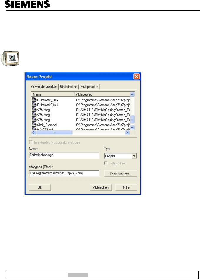
4.1New Project
Start the SIMATIC Manager.
Create a new project with the Name “Color Mixing Plant“.
Preface Installation Project Description Step7 Projekt HMI Station WinCC flexible Project Messages Recipes User Management
T I A Training Document |
Page 15 of 129 |
Module |
|
|
F6 |
Issued: 02/2008 |
|
Operator Control with WinCC flexible 2005 |
Automation and Drives - SCE
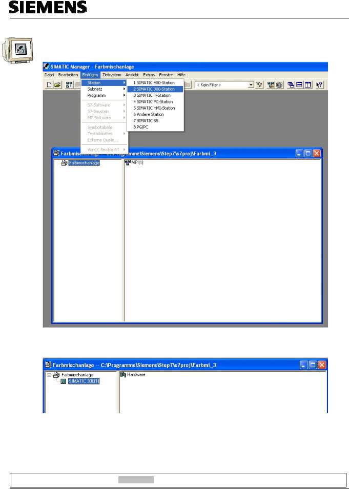
Insert the SIMATIC 300 Station.
By double clicking on Hardware, start the hardware configuration.
Preface Installation Project Description Step7 Projekt HMI Station WinCC flexible Project Messages Recipes User Management
T I A Training Document |
Page 16 of 129 |
Module |
|
|
F6 |
Issued: 02/2008 |
|
Operator Control with WinCC flexible 2005 |

Automation and Drives - SCE
4.2Hardware Configuration
Enter the hardware configuration of the controller you are using. Take note of the settings in the sample configuration.
For our mixing plant, we are using the following hardware:
Slot 1: PS307 2A |
6ES7 307-1BA00-0AA0 |
Slot 2: CPU 314C-2DP |
6ES7 314-6CF00-0AB0 |
The CPU 314C-2DP is assigned the Profibus DP Addr.2 and is connected. The CPU 314C-2DP is assigned the MPI Addr.2 and is connected.
The clock flag is set to MB100.
At the integrated inputs and outputs DI24/DO16, the inputs are set starting with Address 0, and the outputs starting with Address 4.
Save and compile the hardware configuration. Load the hardware to the PLC.
Close the hardware configuration.
Note
The SIMATIC S7 controller can also be simulated with the PLC simulator PLC SIM. However, the simulator has to be started prior to loading the hardware to the CPU.
Preface Installation Project Description Step7 Projekt HMI Station WinCC flexible Project Messages Recipes User Management
T I A Training Document |
Page 17 of 129 |
Module |
|
|
F6 |
Issued: 02/2008 |
|
Operator Control with WinCC flexible 2005 |

Automation and Drives - SCE
4.3Library of the Color Mixing Plant
First, the library with the program blocks has to be imported to the SIMATIC Manager. To this end, select the function Dearchive in the menu File.
From the template directory, select the file “Color mixing plant_Library“.
Click on the button “Open“.
Preface Installation Project Description Step7 Projekt HMI Station WinCC flexible Project Messages Recipes User Management
T I A Training Document |
Page 18 of 129 |
Module |
|
|
F6 |
Issued: 02/2008 |
|
Operator Control with WinCC flexible 2005 |

Automation and Drives - SCE
As destination directory, select the folder “S7LIBS“ in the Step7 directory.
Confirm with OK.
In the following window, click on the button “No“
<<the following objects were dearchived: Projects: None. Libraries: color mixing plant. Do you want to open them now?>>
The project library “Color mixing plant“ was copied to the library directory. Here, all required program blocks are stored.
Preface Installation Project Description Step7 Projekt HMI Station WinCC flexible Project Messages Recipes User Management
T I A Training Document |
Page 19 of 129 |
Module |
|
|
F6 |
Issued: 02/2008 |
|
Operator Control with WinCC flexible 2005 |

Automation and Drives - SCE
4.4Assignment List
Open the project window in the symbol table.
Enter the symbol assignments in the symbol table.
Address |
|
Data Type |
|
|
Comment |
|
||||||||||||
|
|
|
|
|
|
|
|
|
|
|
|
|
|
|
|
|
|
|
|
|
|
|
|
|
Inflow valve Tank 1 |
||||||||||||
|
|
|
|
|
|
|
|
|
|
|
|
|
|
|
|
|
||
|
|
|
|
|
|
Outflow valve Tank 1 |
||||||||||||
|
|
|
|
|
|
|
|
|
|
|
|
|
|
|
|
|
|
|
|
|
|
|
|
|
Inflow valve Tank 2 |
||||||||||||
|
|
|
|
|
|
|
|
|
|
|
|
|
|
|
|
|
|
|
|
|
|
|
|
|
Outflow valve Tank 2 |
||||||||||||
|
|
|
|
|
|
|
|
|
|
|
|
|
|
|
|
|
|
|
|
|
|
|
|
|
|
Inflow valve Tank 3 |
|||||||||||
|
|
|
|
|
|
|
|
|
|
|
|
|
|
|
|
|
||
|
|
|
|
|
|
Outflow valve Tank 3 |
||||||||||||
|
|
|
|
|
|
|
|
|||||||||||
|
|
|
|
|
|
Outflow valve Container |
||||||||||||
|
|
|
|
|
|
|
|
|
|
|
|
|
|
|
|
|
|
|
|
|
|
|
|
|
Motor for the mixer |
||||||||||||
|
|
|
|
|
|
|
|
|
|
|
|
|
|
|
|
|||
|
|
|
|
|
|
|
Lamp for program start enable |
|||||||||||
|
|
|
|
|
|
|
|
|
|
|
|
|
|
|
|
|||
|
|
|
|
|
|
|
Lamp for automatic mode |
|||||||||||
|
|
|
|
|
|
|
|
|
|
|
|
|||||||
|
|
|
|
|
|
|
Lamp for manual mode |
|||||||||||
|
|
|
|
|
|
|
|
|
|
|
|
|
|
|
|
|
|
|
|
|
|
|
|
|
|
Manual-Automatic switch Auto = 1 |
|||||||||||
|
|
|
|
|
|
|
|
|
|
|
|
|
|
|
||||
|
|
|
|
|
|
|
Start program |
|||||||||||
|
|
|
|
|
|
|
|
|
|
|
|
|
|
|
|
|
|
|
|
|
|
|
|
|
|
Manual operation for inflow valve of Tank 1 |
|||||||||||
|
|
|
|
|
|
|
|
|
|
|
|
|
|
|||||
|
|
|
|
|
|
|
Manual operation for outflow valve of Tank |
|||||||||||
|
|
|
|
|
|
|
|
|
|
|
|
|
|
|
|
|
|
|
|
|
|
|
|
|
|
Manual operation for inflow valve of Tank |
|||||||||||
|
|
|
|
|
|
|
|
|
|
|
|
|
|
|||||
|
|
|
|
|
|
|
Manual operation for outflow valve of Tank |
|||||||||||
|
|
|
|
|
|
|
|
|
|
|
|
|
|
|||||
|
|
|
|
|
|
|
Manual operation for inflow valve of Tank 3 |
|||||||||||
|
|
|
|
|
|
|
|
|
|
|
|
|
|
|||||
|
|
|
|
|
|
|
Manual operation for outflow valve of Tank |
|||||||||||
|
|
|
|
|
|
|
|
|
|
|
|
|
||||||
|
|
|
|
|
|
|
Manual operation for outflow valve of container |
|||||||||||
|
|
|
|
|
|
|
|
|
|
|
|
|
||||||
|
|
|
|
|
|
|
Manual operation for mixer motor |
|||||||||||
|
|
|
|
|
|
|
|
|
|
|
|
|||||||
|
|
|
|
|
|
|
Specified amount for Tank1 |
|||||||||||
|
|
|
|
|
|
|
|
|
|
|
|
|||||||
|
|
|
|
|
|
|
Specified amount for Tank2 |
|||||||||||
|
|
|
|
|
|
|
|
|
|
|
|
|||||||
|
|
|
|
|
|
|
Specified amount for Tank 3 |
|||||||||||
|
|
|
|
|
|
|
|
|
|
|
|
|||||||
|
|
|
|
|
|
|
Tank content Tank1 |
|||||||||||
|
|
|
|
|
|
|
|
|
|
|
|
|||||||
|
|
|
|
|
|
|
Tank content Tank2 |
|||||||||||
|
|
|
|
|
|
|
|
|
|
|
||||||||
|
|
|
|
|
|
|
Tank content Tank3 |
|||||||||||
|
|
|
|
|
|
|
|
|
|
|||||||||
|
|
|
|
|
|
|
Tank content of container |
|||||||||||
|
|
|
|
|
|
|
|
|
|
|||||||||
|
|
|
|
|
|
|
Mixer time in S5 format |
|||||||||||
|
|
|
|
|
|
|
|
|
|
|||||||||
|
|
|
|
|
|
|
Idle time in S5 format |
|||||||||||
Save and Close the symbol table.
Preface Installation Project Description Step7 Projekt HMI Station WinCC flexible Project Messages Recipes User Management
T I A Training Document |
Page 20 of 129 |
Module |
|
|
F6 |
Issued: 02/2008 |
|
Operator Control with WinCC flexible 2005 |
Automation and Drives - SCE
4.5Control Program
4.5.1Function Block FB1
With the right mouse key, generate the FB1 in the folder Blocks.
Enter the symbolic name and the symbol comment.
Select the programming language “FBD“.
Place the check mark at Multi-instance capability.
Confirm with OK.
Preface Installation Project Description Step7 Projekt HMI Station WinCC flexible Project Messages Recipes User Management
T I A Training Document |
Page 21 of 129 |
Module |
|
|
F6 |
Issued: 02/2008 |
|
Operator Control with WinCC flexible 2005 |

Automation and Drives - SCE
4.5.2Variable Declaration
Open FB1 with a double click. Enter the following STAT variables.
<<hand_ablauf = manual outflow; hand-zulauf = manual inflow; hand_ablauf_behaelter = manual outflow container>>
Enter the following TEMP variables.
<<ablaufmenge = outflow amount>>
Note
The STAT variables are connected to the operator buttons on touch panel TP177B. The TEMP variables are needed for passing on values in FB1.
Preface Installation Project Description Step7 Projekt HMI Station WinCC flexible Project Messages Recipes User Management
T I A Training Document |
Page 22 of 129 |
Module |
|
|
F6 |
Issued: 02/2008 |
|
Operator Control with WinCC flexible 2005 |
Automation and Drives - SCE
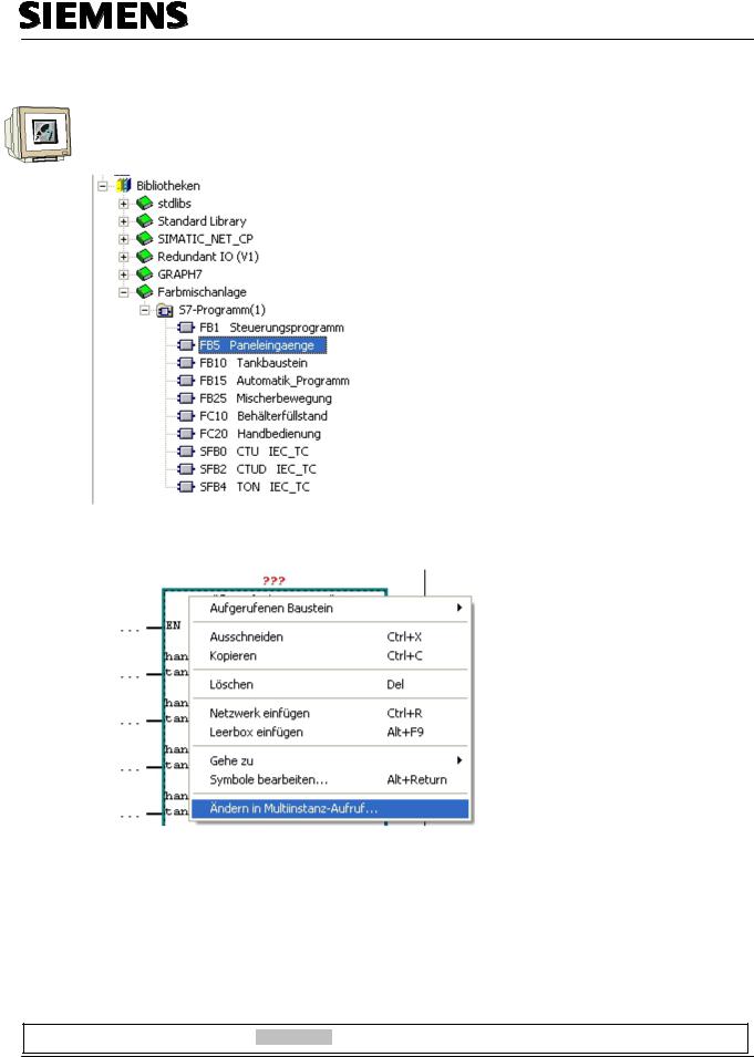
4.5.3Inserting Panel Inputs FB5 as Multi Instance Block from the Program Library
Drag FB5 for the panel inputs from the library “Color mixing plant“ to Network 1.
This block is needed for connecting the input signals from the panel to the inputs of the controller.
Right click on the inserted block and select “Change in multi-instance call“.
Preface Installation Project Description Step7 Projekt HMI Station WinCC flexible Project Messages Recipes User Management
T I A Training Document |
Page 23 of 129 |
Module |
|
|
F6 |
Issued: 02/2008 |
|
Operator Control with WinCC flexible 2005 |
Automation and Drives - SCE
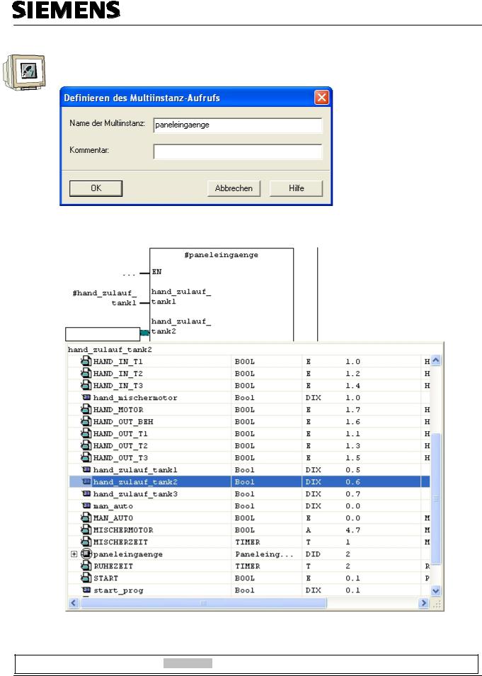
Enter the name “panel inputs“.
Confirm with OK.
Wire the upper 10 inputs of the block to the STAT variables.
Preface Installation Project Description Step7 Projekt HMI Station WinCC flexible Project Messages Recipes User Management
T I A Training Document |
Page 24 of 129 |
Module |
|
|
F6 |
Issued: 02/2008 |
|
Operator Control with WinCC flexible 2005 |
Automation and Drives - SCE
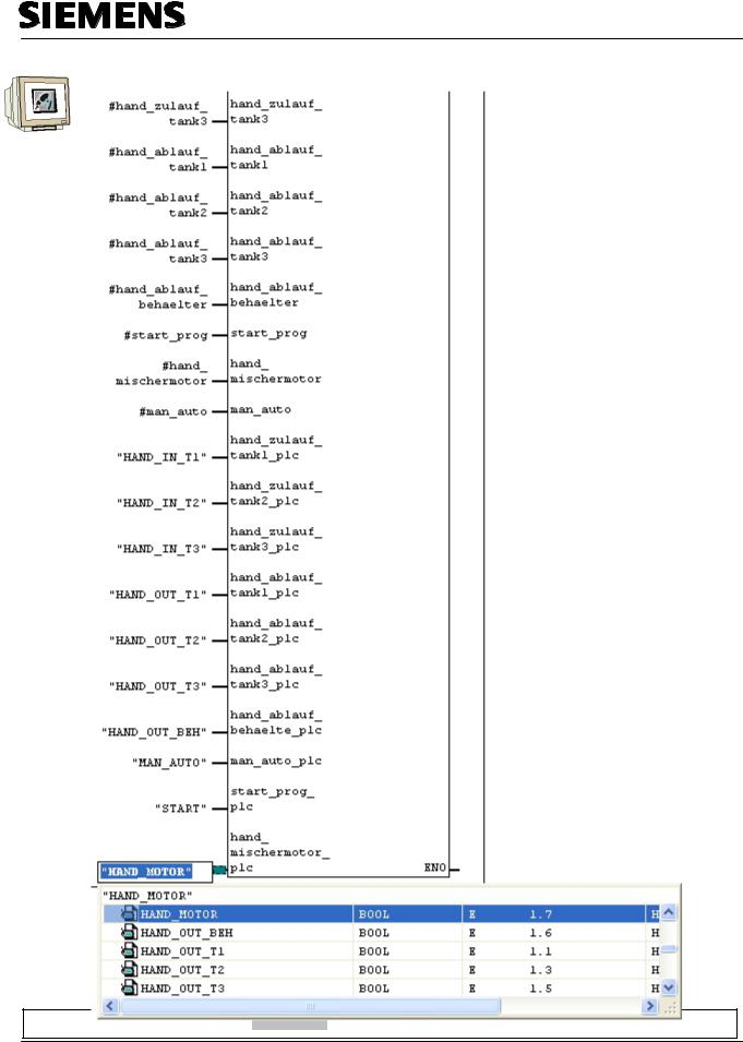
Wire the lower 10 inputs of the block with the symbolic names.
Preface Installation Project Description Step7 Projekt HMI Station WinCC flexible Project Messages Recipes User Management
T I A Training Document |
Page 25 of 129 |
Module |
|
|
F6 |
Issued: 02/2008 |
|
Operator Control with WinCC flexible 2005 |

Automation and Drives - SCE
4.5.4Tank Block FB10
Create a new network.
Drag the tank block FB10 from the library to Network 2. Right click on the inserted block.
Select “Change to multi-instance call“
Enter the name “tank1“. Confirm with OK.
This block contains the two step control and the calculations for simulating the level. When level sensors are used, only the two step control would be necessary. Wire the block’s inputs.
Preface Installation Project Description Step7 Projekt HMI Station WinCC flexible Project Messages Recipes User Management
T I A Training Document |
Page 26 of 129 |
Module |
|
|
F6 |
Issued: 02/2008 |
|
Operator Control with WinCC flexible 2005 |

Automation and Drives - SCE
Repeat the steps for Tank2 in Network 3.
Note
Writing the symbolic names in “CAPITALS“ and the variables in “lower case letters“ makes better assignments possible.
Preface Installation Project Description Step7 Projekt HMI Station WinCC flexible Project Messages Recipes User Management
T I A Training Document |
Page 27 of 129 |
Module |
|
|
F6 |
Issued: 02/2008 |
|
Operator Control with WinCC flexible 2005 |
Automation and Drives - SCE
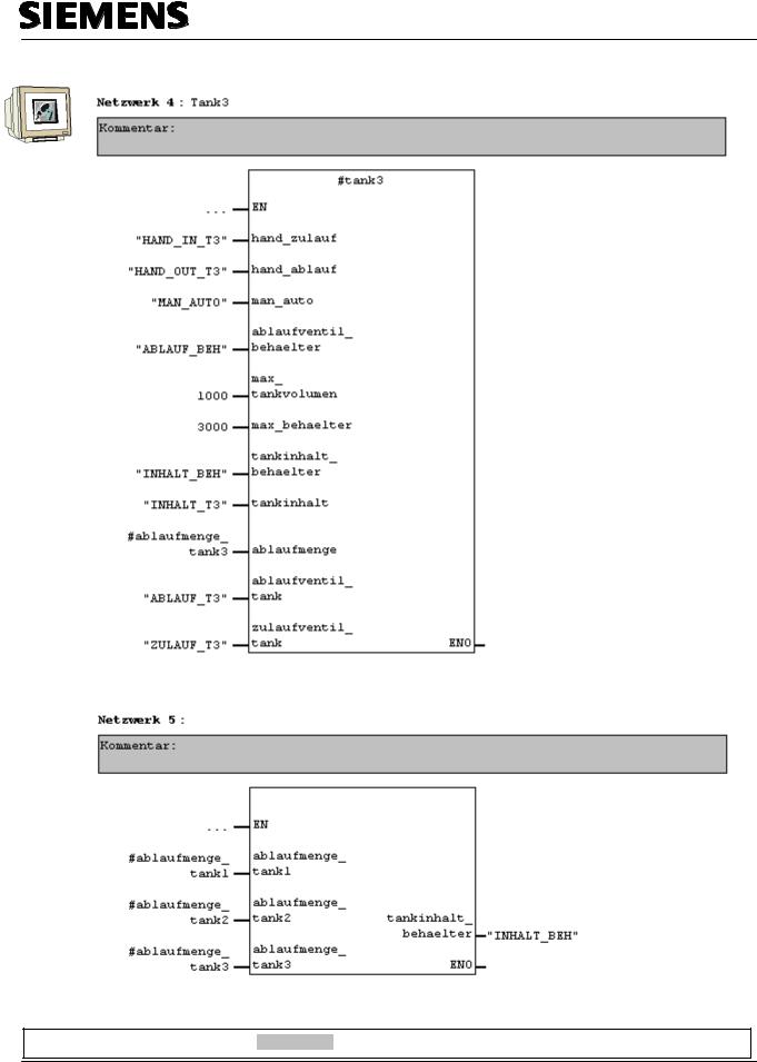
Repeat the steps for Tank3 in Network 4.
Create a new network and drag tank block FC10 from the library to Network 5.
Calculating the container level
Container Level
Preface Installation Project Description Step7 Projekt HMI Station WinCC flexible Project Messages Recipes User Management
T I A Training Document |
Page 28 of 129 |
Module |
|
|
F6 |
Issued: 02/2008 |
|
Operator Control with WinCC flexible 2005 |
Automation and Drives - SCE
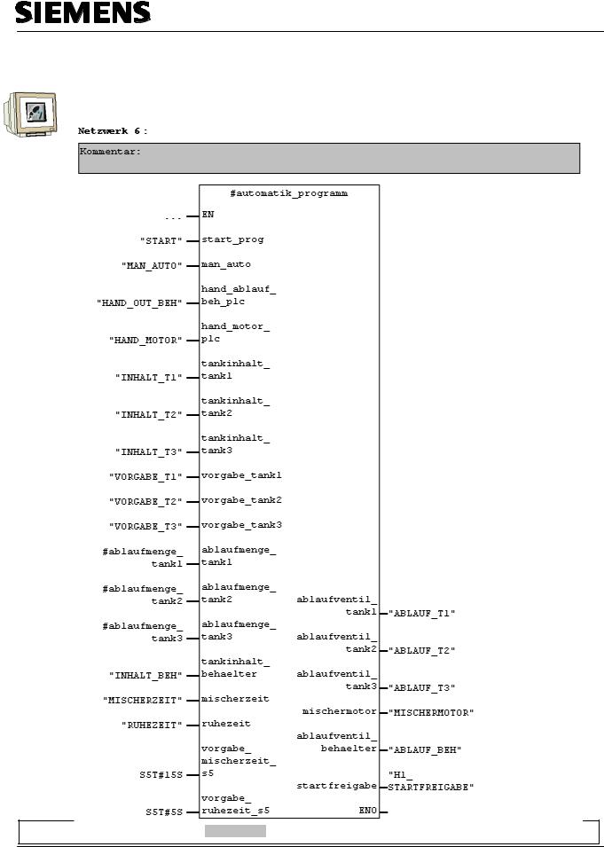
4.5.5Automatic Program Sequence FB15
The automatic program sequence is described in the plant description.
Automatic Program Sequence
Preface Installation Project Description Step7 Projekt HMI Station WinCC flexible Project Messages Recipes User Management
T I A Training Document |
Page 29 of 129 |
Module |
|
|
F6 |
Issued: 02/2008 |
|
Operator Control with WinCC flexible 2005 |

Automation and Drives - SCE
4.5.6Manual Operation FC20
Create a new network and drag the FC20 from the library to Network 7.
This block contains the manual operation of the tanks’ outflow valves in the manual mode.
This FC20 has to be called after the FB15, since the automatic valve operations of the FB15 have to be overwritten by the manual mode in FC20.
Wire the inputs of the block.
Manual mode of the outflow valves of the tanks
Preface Installation Project Description Step7 Projekt HMI Station WinCC flexible Project Messages Recipes User Management
T I A Training Document |
Page 30 of 129 |
Module |
|
|
F6 |
Issued: 02/2008 |
|
Operator Control with WinCC flexible 2005 |
 Loading...