

Page 1

SINUMERIK 840C
Software Version 6
User's Guide
09.2001 Edition
OEM Version for Windows
TM
Manufacturer Documentation
Page 2

Page 3

SINUMERIK 840C
Introduction 1
Software Version 6
User's Guide
OEM Version for Windows
Overview and Installation 2
System Structure of 840C 3
Alarms 4
DDE Interface 5
Sample Programs 6
Appendix
Applies to
Control Software Version
SINUMERIK 840C/CE 6
(Standard/Export version)
09.01 Edition
I Code Interface A1
Reference Guide A2
Function Identifiers
for Data Management A3
Abbreviations A4
Page 4

SINUMERIK Documentation
Printing history
Brief details of this edition and previous editions are listed below.
The status of each edition is shown by the code in the "Remarks" column.
Status code in the "Remarks" column:
A ...........................New documentation.
B ...........................Unrevised reprint with new Order No.
C ...........................Revised edition with new status.
Edition Order No. Remarks
06.94 6FC5198-3AA70-0BP0 A
11.94 6FC5198-4AA70-0BP0 C
12.95 6FC5198-5AA70-0BP0 C
04.96 6FC5198-5AA70-0BP1 C
07.97 6FC5198-6AA70-0BP0 C
01.99 6FC5198-6AA70-0BP1 C
09.01 6FC5198-6AA70-0BP2 C
This manual is included in the documentation on CD-ROM (DOCONCD)
Edition Order No. Remarks
10.01 6FC5 198-6CA00-0BG2 C
Trademarks
SIMATIC
, SIMATIC HMI, SIMATIC NET, SIROTEC, SINUMERIK and SIMODRIVE are
registered trademarks of Siemens AG. Other brands mentioned in this publication might be trademarks
whose use by a third party for his own purposes could violate the rights of the proprietors.
Further information is available on the Internet under:
http:/www.ad.siemens.de/sinumerik
This publication was produced with Microsoft Word V 7.0
and Designer V 4.0.
The reproduction, transmission or use of this document or its contents
is not permitted without express written authority. Offenders will be
liable for damages. All rights, including rights created by patent grant
or registration of a utility model or design, are reserved.
Siemens AG 2001. All rights reserved
Other functions not described in this documentation might be
executable in the control. This does not, however, represent an
obligation to supply such functions with a new control or when
servicing.
We have checked that the contents of this document correspond to the
hardware and software described. Nonetheless, differences might exist
and therefore we cannot guarantee that they are completely identical.
The information contained in this document is, however, reviewed
regularly and any necessary changes will be included in the next
edition. We welcome suggestions for improvement.
Subject to change without prior notice.
Order No. 6FC5198-6AA70-0BP2 Siemens-Aktiengesellschaft
Printed in the Federal Republic of Germany
Page 5

09.01
Preliminary Remarks
Notes for the reader: The SINUMERIK documentation is organized in 4 parts:
• General Documentation
• User Documentation
• Manufacturer Documentation and
• Service Documentation
This manual is intended for OEM customers and manufacturers of
machine tools who use the SINUMERIK 840C OEM Version for
Windows.
The software of the integrated MMC of the SINUMERIK 840C OEM
Version for Windows includes the operating systems:
• MS-DOS 6.22
• MS-Windows for Workgroups 3.11 (WfW 3.11)
• FlexOS
The control can be started up both under Windows for Workgroups
3.11 and FlexOS. If FlexOS is booted, the control is functionally
identical with the SINUMERIK 840C/CE (basic version).
Booting under WfW 3.11 provides the OEM customer or machine
manufacturer with a way of integrating his own technological expertise
into the control under a widely used operating system platform.
Moreover, with MS Windows it is possible to make use of the wide
range of inexpensive software for technical and industrial applications
on the control.
This manual describes the method of operation and parameter options
of the internal software modules of the integrated MMC and provides
the user with the information required to develop and integrate his own
applications into the software system.
This manual is intended to be introductory, so the reader does not
need any special knowledge except for experience of NC technology
and a basic knowledge of how to program the MS Windows operating
system.
For the acquisition or improvement of knowledge of these subjects, we
recommend the training courses provided by SIEMENS. Please
consult your local SIEMENS branch office or national company for
further information.
Page 6

09.01
The Manufacturer Documentation for the 840C control is subdivided
into the following parts:
• Interface
- Part 1: Signals
- Part 2: Connection Conditions
• PLC 135 WB/WB2/WD Planning Guide
• Function Macros
• Planning Guides
- Package 0: Basic Functions
- Package 1: Tool Management
- Package 4/5: Computer Link
- Package 7: Code Carriers
- Package 8: PLC Controlled Data Input/Output
There are also SINUMERIK publications that apply to all SINUMERIK
controls (e.g. Measuring Cycles, CL 800 Cycle Language)
You can obtain more details from your local Siemens branch office or
national company.
When using SINUMERIK Safety Integrated (SI) in connection with
OEM applications for 840 C Windows, please observe the notes
given in the Safety Integrated documentation.
This manual only applies to the control
SINUMERIK 840C, OEM Version for Windows,
Software Version 4, 5 and 6
For more detailed information on the MS DOS and MS Windows
operating systems, please refer to the original documentation of the
Microsoft Corporation
MS-DOS is a registered trademark of the Microsoft Corporation
is a registered trademark of the Microsoft Corporation
MS
Microsoft
is a registered trademark of the Microsoft Corporation
Windows
Visual Basic
Visual C++
ROBOHELP
is a trade name of the Microsoft Corporation
is a trade name of the Microsoft Corporation
is a trade name of the Microsoft Corporation
is a registered trademark of the Blue Sky Software Corporation
Page 7
09.01
Warning notes
The following warning notes with varying degrees of severity are used in the documentation:
Danger
Indicates an imminently hazardous situation which, if not avoided, will
result in death or serious injury or in substantial property damage.
Warning
Indicates a potentially hazardous situation which, if not avoided, could
result in death or serious injury or in substantial property damage.
Caution
Used with the safety alert symbol indicates a potentially hazardous
situation which, if not avoided, may result in minor or moderate injury or
in property damage.
Caution
Used without safety alert symbol indicates a potentially hazardous
situation which, if not avoided, may result in property damage.
Notice
Used without the safety alert symbol indicates a potential situation
which, if not avoided, may result in an undesirable result or state.
Page 8

09.01
Page 9

Table of Contents
1 Introduction ..................................................................................................................1-1
2 Overview and Installation............................................................................................ 2-1
2.1 System requirements ..................................................................................................... 2-2
2.2 Installation procedure..................................................................................................... 2-2
2.3 Additional notes on the OEM test environment.............................................................. 2-3
2.4 Directory structure of the OEM test environment...........................................................2-4
3 System Structure of 840C ........................................................................................... 3-1
3.1 Overview ........................................................................................................................ 3-1
3.1.1 Hardware concept .................................................................................................... 3-1
3.1.2 Software structure of the integrated PC ................................................................... 3-2
3.1.3 Basic modules .......................................................................................................... 3-4
3.1.4 NCK / PLC / SIMODRIVE 611-D interface ...............................................................3-6
3.2 Hardware configuration..................................................................................................3-7
3.2.1 Brief description of hardware.................................................................................... 3-7
3.2.2 Integrated PC ........................................................................................................... 3-9
3.2.2.1 Block diagram........................................................................................................... 3-10
3.2.2.2 Processor 80486....................................................................................................... 3-10
3.2.2.3 System memory........................................................................................................ 3-10
3.2.2.4 Mass storage medium .............................................................................................. 3-12
3.2.2.5 Watch Dog................................................................................................................3-12
3.2.2.6 VGA video graphic unit............................................................................................. 3-12
3.2.2.7 Electrical and mechanical data................................................................................. 3-12
3.2.2.8 PCMCIA software support........................................................................................ 3-12
3.2.1.9 I/O address areas..................................................................................................... 3-26
3.2.1.10 Interrupt assignments............................................................................................... 3-27
3.2.3 Hardware interfaces on the MMC CPU ....................................................................3-28
3.2.3.1 Serial interface RS232 (COM1)................................................................................ 3-28
3.2.3.2 Serial interface RS232/TTY (COM2)........................................................................ 3-28
3.2.3.3 Parallel interface (LPT1)........................................................................................... 3-29
3.2.3.4 Keyboard interface.................................................................................................... 3-30
3.2.3.5 RGB interface........................................................................................................... 3-30
3.2.3.6 VGA analog interface (PC-compatible)..................................................................... 3-30
3.2.3.7 Hardware settings on the MMC CPU ....................................................................... 3-31
3.2.3.8 Operator controls and displays................................................................................. 3-31
3.2.3.9 SINUMERIK link bus................................................................................................. 3-31
3.2.3.10 AT96 local bus..........................................................................................................3-32
3.2.3.11 Use of interfaces COM3 and COM4......................................................................... 3-33
3.2.4 The AT box............................................................................................................... 3-34
3.2.4.1 Overview................................................................................................................... 3-34
3.2.4.2 The ISA local bus in the AT rack .............................................................................. 3-35
3.2.4.3 AT bus power supply................................................................................................ 3-36
3.2.4.4 Using PC/AT cards................................................................................................... 3-36
3.3 New features in software version 6................................................................................3-38
3.3.1 Transmission of key code to PLC............................................................................. 3-38
Page 10

3.3.2 Program frame for WINDOWS and DOS applications (SW 6 and higher)................3-39
3.3.2.1 Integrating Windows programs.................................................................................3-39
3.3.2.2 Integrating DOS programs........................................................................................3-40
3.3.3 Storing the alarm messages as a file for DOS applications (SW 6 and higher)........3-42
3.3.4 Mode switchover without displaying Siemens pictures (SW 6 and higher)...............3-43
3.4 Basic modules ................................................................................................................3-44
3.4.1 Application structure and operation ..........................................................................3-44
3.4.1.1 Display applications..................................................................................................3-45
3.4.1.2 Background applications...........................................................................................3-45
3.4.1.3 Operation via softkeys ..............................................................................................3-45
3.4.2 Start-up of the control ...............................................................................................3-46
3.4.2.1 Merging files with the "MIXER" program...................................................................3-46
3.4.2.2 Merging initialization files (*.INI)................................................................................3-47
3.4.2.3 Merging batch files (*.BAT).......................................................................................3-49
3.4.2.4 Merging (CONFIG.SYS) configuration files ..............................................................3-51
3.4.2.5 Merging autostart files (REG_AUTO.CFG)...............................................................3-53
3.4.3 Area switchover ........................................................................................................3-54
3.4.3.1 Configuration options in REGIE.INI ..........................................................................3-54
3.4.3.2 Switching off the control............................................................................................3-59
3.4.3.3 Express shutdown.....................................................................................................3-60
3.4.3.4 Autostart function via REG_AUTO.CFG...................................................................3-62
3.4.3.5 Starting applications via the job list...........................................................................3-65
3.4.4 NCK task...................................................................................................................3-66
3.4.4.1 Output window..........................................................................................................3-66
3.4.4.2 Menus and softkey labeling ......................................................................................3-67
3.4.4.3 Language dependence.............................................................................................3-67
3.4.4.4 Available areas (menus) of the NCK.........................................................................3-68
3.4.4.5 Storing the menus in the NCK area..........................................................................3-68
3.4.4.6 Changing the operating mode...................................................................................3-68
3.4.4.7 PLC inserts ...............................................................................................................3-68
3.4.4.8 Color settings for NCK task and alarm/message line ...............................................3-69
3.4.5 Keyboard driver.........................................................................................................3-73
3.4.5.1 Operator panel keyboard..........................................................................................3-74
3.4.5.2 Full keyboard on KYRU II .........................................................................................3-74
3.4.5.3 MF2 keyboard on SBC..............................................................................................3-74
3.4.5.4 Key codes.................................................................................................................3-75
3.4.5.5 Kyru expansions .......................................................................................................3-77
3.4.5.6 New features in Software version 5.1.......................................................................3-79
3.4.6 Data manager...........................................................................................................3-92
3.4.6.1 Reading files in and out ............................................................................................3-93
3.4.6.2 Editor "WEdit" ...........................................................................................................3-95
3.4.6.3 Expansion options.....................................................................................................3-98
3.4.6.4 Access rights in data management...........................................................................3-100
3.4.6.5 The NCK data selector..............................................................................................3-101
3.4.6.6 Data handling via DB 37...........................................................................................3-102
3.4.7 V24 parameterization................................................................................................3-105
3.4.8 Softkey manager.......................................................................................................3-106
3.4.8.1 Setting/deleting characters in the RECALL field.......................................................3-109
3.4.8.2 NCK font ...................................................................................................................3-110
3.4.8.3 Operating the softkey menu with an external keyboard............................................3-110
3.4.8.4 Operating the softkey menu with the mouse.............................................................3-110
3.4.9 Clock.........................................................................................................................3-111
3.4.10 Watchdog..................................................................................................................3-111
3.4.11 Access protection......................................................................................................3-111
Page 11

3.4.11.1 Password management............................................................................................ 3-112
3.4.11.2 Setting up the password levels................................................................................. 3-114
3.4.12 FDD/MSD service display......................................................................................... 3-115
3.4.13 OEM information....................................................................................................... 3-115
3.4.14 840C language concept............................................................................................ 3-116
3.4.14.1 Change language .....................................................................................................3-116
3.4.14.2 Method of operation.................................................................................................. 3-117
3.4.14.3 Special features of initial start-up.............................................................................. 3-118
3.4.15 840C directory tree................................................................................................... 3-119
3.5 SIN840C.INI...................................................................................................................3-120
4 Alarms...........................................................................................................................4-1
5 DDE Interface................................................................................................................5-1
5.1 Windows DDE................................................................................................................5-1
5.1.1 Establishing a link..................................................................................................... 5-1
5.1.2 Types of link..............................................................................................................5-2
5.1.2.1 Static data................................................................................................................. 5-2
5.1.2.2 Dynamic updating..................................................................................................... 5-3
5.1.2.3 Notification of change...............................................................................................5-4
5.1.3 Terminating links....................................................................................................... 5-6
5.1.4 The DDEML library................................................................................................... 5-6
5.2 DDE server of the SIN 840C OEM version for Windows................................................ 5-7
5.2.1 Activating the server................................................................................................. 5-8
5.2.2 Link initiation with the server..................................................................................... 5-8
5.2.3 Time response.......................................................................................................... 5-9
5.3 Alarm handling via DDE.................................................................................................5-10
5.3.1 Setting alarms........................................................................................................... 5-10
5.3.2 Clear all alarms.........................................................................................................5-11
5.3.3 Reading alarms......................................................................................................... 5-12
5.3.4 Changing the display mode of the alarm/message line............................................ 5-13
5.4 Central status scan......................................................................................................... 5-14
5.5 MMC NCK interface ....................................................................................................... 5-16
5.5.1 Command interface (EXECUTE).............................................................................. 5-16
5.5.1.1 File transfer............................................................................................................... 5-16
5.5.1.2 DELETE_FILE.......................................................................................................... 5-19
5.5.1.3 RENAME_FILE......................................................................................................... 5-19
5.5.2 Read and write accesses.......................................................................................... 5-20
5.5.2.1 Data format............................................................................................................... 5-20
5.5.2.2 Variable names......................................................................................................... 5-20
5.5.2.3 List of the variable names......................................................................................... 5-20
5.5.2.4 Data fields................................................................................................................. 5-25
5.5.2.5 Error messages ........................................................................................................5-25
5.5.3 DDEML access to NC data....................................................................................... 5-29
5.5.3.1 Synchronous reading................................................................................................5-29
5.5.3.2 Asynchronous reading.............................................................................................. 5-30
5.5.3.3 Synchronous writing of NC data...............................................................................5-31
5.5.3.4 Asynchronous writing of NC data ............................................................................. 5-31
5.5.4 Transparent data transmission................................................................................. 5-32
5.5.4.1 How transparent data transmission works................................................................ 5-32
5.5.4.2 Cyclic requests/change requests..............................................................................5-34
Page 12

5.6 MMC PLC interface........................................................................................................5-37
5.6.1 Overview...................................................................................................................5-37
5.6.2 Data exchange on the PLC side...............................................................................5-37
5.6.2.1 Writing to the MMC...................................................................................................5-38
5.6.2.2 Reading from the MMC.............................................................................................5-38
5.6.3 Data exchange on the MMC side..............................................................................5-39
5.6.4 Structure of data packets on the PLC side ...............................................................5-40
5.6.4.1 Structure for receiving...............................................................................................5-40
5.6.4.2 Structure for sending.................................................................................................5-42
5.6.5 MMC-PLC data exchange (examples)......................................................................5-43
5.6.5.1 Reading PLC data (DDE_REQUEST)......................................................................5-43
5.6.5.2 Writing PLC data (DDE_POKE)................................................................................5-44
5.6.5.3 Advise link for PLC data (DDE_ADVISE) .................................................................5-45
5.6.5.4 PLC user program (DDETESST.S5D)......................................................................5-48
5.6.6 Execution of MMC applications by the PLC side......................................................5-51
5.6.6.1 Overview...................................................................................................................5-51
5.6.6.2 Starting an MMC application from the PLC...............................................................5-51
5.6.6.3 Terminating an MMC application from the PLC side ................................................5-52
5.6.6.4 I code description (42EH) .........................................................................................5-52
5.6.6.5 Terminating DOS programs......................................................................................5-55
5.6.6.6 PLC user program (WINOEMST.S5D) .....................................................................5-56
6 Sample Programs.........................................................................................................6-1
6.1 Integration of customer applications...............................................................................6-1
6.1.1 Development systems...............................................................................................6-1
6.1.2 Integration into the OEM test environment ...............................................................6-2
6.1.3 Testing DDE client applications................................................................................6-2
6.1.4 Integration of applications into the control ................................................................6-3
6.2 Sample programs (MS Visual Basic)..............................................................................6-4
6.2.1 Project: Tacho...........................................................................................................6-4
6.2.2 Project: DDETEST....................................................................................................6-7
6.3 Sample programs (MS Windows 3.1 SDK) ....................................................................6-8
6.3.1 Project: VSASERV....................................................................................................6-8
6.3.2 Project: Message......................................................................................................6-9
6.3.3 OEM client ................................................................................................................6-10
6.3.4 OEM client ADVTEST...............................................................................................6-11
6.3.5 Gearbox interpolation................................................................................................6-13
6.4 Network DDE..................................................................................................................6-17
6.4.1 Link initiation for network DDE..................................................................................6-17
6.4.2 Creating a DDE SHARE ...........................................................................................6-17
6.4.3 Network modules......................................................................................................6-19
6.4.4 Summary...................................................................................................................6-19
A1 I Code Interface.............................................................................................................A1-1
A1.1 ADS communication via mailboxes...........................................................................A1-1
A1.2 I code description......................................................................................................A1-2
A1.2.1 Application areas ......................................................................................................A1-2
A1.2.1.1 Single data item and list transfer...............................................................................A1-2
A1.2.1.2 Data transfer extensions...........................................................................................A1-2
A1.2.1.3 Executing functions...................................................................................................A1-2
Page 13

A1.2.1.4 Selective data transfer..............................................................................................A1-3
A1.2.1.5 File transfer............................................................................................................... A1-5
A1.2.1.6 Reserved applications for OEM................................................................................A1-5
A1.2.2 Structure of the I code header.................................................................................. A1-6
A1.2.3 Protocol types...........................................................................................................A1-9
A1.2.3.1 Protocol type 0.......................................................................................................... A1-10
A1.2.3.2 Protocol type 1.......................................................................................................... A1-10
A1.2.3.3 Protocol type 2.......................................................................................................... A1-11
A1.2.3.4 Protocol type 3.......................................................................................................... A1-11
A1.2.3.5 Protocol type 4.......................................................................................................... A1-13
A1.2.3.6 Protocol type 5.......................................................................................................... A1-14
A1.3 Tabular overview of the I code command in SINUMERIK 840C OEM
Version for Windows.................................................................................................A1-15
A2 Reference Guide........................................................................................................... A2-1
A2.1 I code command description.....................................................................................A2-1
A2.1.1 Single data item and list transfer: 1xxH....................................................................A2-1
A2.1.1.1 Read value(s): 01xxH............................................................................................... A2-1
A2.1.1.2 Write value(s): 01xxH...............................................................................................A2-3
A2.1.1.3 Read/write GI buffer: 0117H..................................................................................... A2-6
A2.1.2 Data transfer extensions: 2xxH.................................................................................A2-10
A2.1.2.1 Read service values of axes: 020EH........................................................................ A2-10
A2.1.2.2 Read service values of spindles: 020FH ..................................................................A2-12
A2.1.2.3 Read/write PLC data via PLC DAD: 0210H.............................................................. A2-14
A2.1.2.4 Read/write PLC data blocks: 0211H......................................................................... A2-16
A2.1.2.5 Read PLC error ID: 0212H....................................................................................... A2-19
A2.1.2.6 Read control mode: 0213H....................................................................................... A2-20
A2.1.2.7 Read/write program pointers: 0216H........................................................................ A2-21
A2.1.3 Command execution: 4xxH.......................................................................................A2-23
A2.1.3.1 Abort current I code request: 0400H ........................................................................ A2-23
A2.1.3.2 Initiate drift compensation: 0419H............................................................................ A2-24
A2.1.3.3 Initiate file transfer: 0421H........................................................................................ A2-25
A2.1.3.4 Initiating job list processing / workpiece transfer with Windows applications............ A2-31
A2.1.3.5 Select workpiece name / machining program: 0422H.............................................. A2-32
A2.1.3.6 Start / stop an MMC application from the PLC side: 042EH..................................... A2-34
A2.1.3.7 Express shutdown: 042FH........................................................................................A2-37
A2.1.4 Selective data transfer: 5xxH.................................................................................... A2-38
A2.1.4.1 Transfer data block description to the NCK: 0500H .................................................A2-38
A2.1.4.2 Delete DBB from NCK: 0501H ................................................................................. A2-40
A2.1.4.3 DBB data transfer 0502H ......................................................................................... A2-41
A2.1.4.4 Read DBB directory of NCK: 0503H......................................................................... A2-43
A2.1.4.5 Issue cyclic request/change request: 0504H............................................................ A2-44
A2.1.4.6 Delete cyclic request/change request: 0505H.......................................................... A2-46
A2.1.5 Process file: 6xxH.....................................................................................................A2-47
A2.1.5.1 Open file: 0601 H...................................................................................................... A2-47
A2.1.5.2 Close file: 0602H......................................................................................................A2-50
A2.1.5.3 Read file: 0603H.......................................................................................................A2-51
A2.1.5.4 File transfer NCK
A2.1.5.5 Write file: 0604H....................................................................................................... A2-54
A2.1.5.6 File transfer MMC
A2.1.5.7 Delete file: 0605H..................................................................................................... A2-57
A2.1.5.8 Rename file: 0606H..................................................................................................A2-59
A2.1.5.9 Display directory: 0607H...........................................................................................A2-60
A2.1.5.10 Read/write file attribute: 0608H................................................................................A2-62
A2.2 PLC function macros FX73/FX74............................................................................. A2-64
→ MMC (MMC: Services/NC/Save Start).................................... A2-53
→ NCK (MMC: Services/NC/Load Start) .................................... A2-56
Page 14

A2.2.1 Function macro FX73, OEM-SEND..........................................................................A2-64
A2.2.1.1 Additional information ...............................................................................................A2-65
A2.2.1.2 Block call (FX73: OEM-SEND) .................................................................................A2-65
A2.2.1.3 Signal description......................................................................................................A2-66
A2.2.1.4 FX73 behavior on restart..........................................................................................A2-66
A2.2.2 Function macro FX74, OEM-EMPF..........................................................................A2-67
A2.2.2.1 Additional information ...............................................................................................A2-68
A2.2.2.2 Block call (FX 74: OEM-EMPF) ................................................................................A2-68
A2.2.2.3 Signal description......................................................................................................A2-69
A2.2.2.4 FX74 behavior on restart..........................................................................................A2-69
A2.2.3 OEM information bit..................................................................................................A2-70
A2.2.4 Acknowledgements...................................................................................................A2-70
A2.2.4.1 Error lists for FX73/FX74..........................................................................................A2-71
A2.2.5 Transmission times...................................................................................................A2-73
A3 Function Identifiers for Data Management ................................................................A3-1
A3.1 Function group: delete..............................................................................................A3-2
A3.2 Function group: edit..................................................................................................A3-3
A3.3 Function group: copy/duplicate.................................................................................A3-4
A3.4 Function group: create..............................................................................................A3-8
A4 Abbreviations................................................................................................................A4-1
Page 15

1 Introduction
09.01
1 Introduction
More and more often machine tool manufacturers are faced with the task not only of developing
standardized machine tools but also special solutions for manufacturing technology. In particular,
higher and higher demands are being placed on the functionality of a CNC control. The demands are
often machine-specific and cannot be fully covered by standard products.
On the other hand, there is a desire to use the freedom afforded by the control to give it its own
appearance and/or include technological know-how. Previous man-machine interfaces (MMC) were
mostly based on control-specific software systems and demanded special knowledge of the solution in
question. A further disadvantage of such systems is their "closed" character which often means that
function expansions can only be included with great effort.
Today, there is a demand for "open-ended" control systems. This applies not only to the user interfaces
and the operating system but also to the entire computer hardware. To meet this demand, SIEMENS
has developed the SINUMERIK 840C OEM Version for Windows, an AT compatible MMC that is based
on the "open" operating systems MS-DOS 6.22 and MS Windows for Workgroups 3.11.
The MMC variation permits the use of numerous commercially available hardware modules in
conjunction with the AT box and therefore the integration of existing hardware solutions directly into the
control. The applications of such solutions include:
• Remote diagnostics
• Measuring data acquisition for quality assurance and process control
• MDA/PDA systems (machine and production data acquisition)
• DNC systems (program management and transmission)
Moreover, it is possible to benefit directly from the advantages of the broad range of industrial and
commercial software available. This means that the same programming workstation software with the
same user-friendliness can be used both on an external PC during work preparation and directly on the
control.
For customer developments, Windows for Workgroups 3.11 provides a reliable and stable platform and
a minimization of compatibility problems in the future. Moreover, this operating system ensures great
flexibility and cost-effective network-capability for the entire control system. With the pr ogramming tools
available on the market, the machine-tool manufacturer has the option of developing his own
applications and integrating them into the control.
With Visual Basic for Windows, Microsoft has developed a programming tool that cleverly combines the
advantages of Windows with the programming language Basic. There is scarcely another programming
system with which it is so easy to write Windows programs. Using predefined "Custom Controls", even
a beginner can develop professional Windows user interfaces in a simple way. Windows and menus
can be opened and closed with simple program commands and the input and output of the program
user can be managed and visualized.
However, anyone aiming at professional development cannot do without Visual C++. C++ is currently
the first choice when it comes to solving complex programming problems in a simple way. With visual C
it is possible not only to write programs for Windows but also under Windows, and that faster and more
easily then ever before. Integrated tools such as AppWizard and ClassWizard save the programmer a
lot of time-consuming and error-prone administration work, allowing him to concentrate on the actual
problem to be solved.
©
Siemens AG 2001. All Rights Reserved 6FC5198-6AA70 1-1
SINUMERIK 840C OEM Version for Windows (BN)
Page 16

1 Introduction
09.01
Windows applications can exchange data with the NCK, PLC and 611D via the DDE interface defined
by Microsoft (Dynamic Data Exchange). Via the DDE server, which is also part of the OEM package,
data are transferred from the applications and from and to the NCK, PLC and 611D. The methods
"POKE" (write data), "REQUEST" (read data) and "EXECUTE" (commands for file transfer) are
implemented. Towards the PLC the "ADVISE" method is also implemented. The data that can be
accessed via the DDE server include machine data, setting data, PLC data blocks, part programs etc.
Simply by entering applications in an initialization file, they are integrated into the area switchover and
can be started either automatically when the control is booted or by the user by means of softkey or
PLC command. Examples of such customer applications include:
• Tool management and visualization
• Pallet management
• Job management
• Machine diagnosis
With the OEM package, the machine-tool manufacturer obtains not only the DDE server and a few
library routines but also a complete simulation and test environment for an external PC. With a
commercially available programming tool (e.g. Visual Basic, Visual C++, etc.) the machine-tool
manufacturer can develop and test his own applications on an external PC.
The following section of this documentation deals with the requirements for and the installation of the
OEM test environment and the OEMFORM alarm tool.
Chapter 3 provides a system description of SINUMERIK 840C OEM Version for Windows. This
description includes both the hardware architecture of the control and the method of operation and
parameterization of the Siemens basic modules.
The alarm concept described in previous editions in Chapter 4 has been taken out to form a separate
documentation from the current software version on.
The next section contains a brief introduction to the method of operation of the Windows DDE and a
detailed discussion of the various communications options of OEM applications with the NCK and PLC.
The DDE section is completed with a description of some sample programs that show the reader how
to integrate his own applications and serve as a guide for the development of custom applications.
■
1-2
©
Siemens AG 2001. All Rights Reserved 6FC5198-6AA70
SINUMERIK 840C OEM Version for Windows (BN)
Page 17

2 Overview and Installation
09.01
2 Overview and Installation
The OEM package comprises a PC test and simulation environment of the SINUMERIK 840C with
which customer applications can be tested before they are loaded into the control. The package also
contains several test utilities and sample programs including all the source files and resources to
introduce you to program development for SINUMERIK 840C OEM Version for Windows. You can also
load the sample programs directly into the control, for example, to perform runtime measurements of
the data transfer between the MMC and the NCK or the MMC and the PLC. You will find the simulation
and test environment on the four diskettes labeled:
"SINUMERIK 840 C/CE OEM Package Windows DISK x V06.04.01"
The installation programs will expand each of the necessary files and copy them into the correct
directory so that the programs function correctly.
If you have any questions regarding installation, please contact you local Siemens branch office or
Siemens national company.
©
Siemens AG 2001. All Rights Reserved 6FC5198-6AA70 2-1
SINUMERIK 840C OEM Version for Windows (BN)
Page 18

2 Overview and Installation
09.01
2.1 System requireme nts
Your PC must fulfil the minimum requirements listed below if the test environment is to function
correctly.
Hardware: 25 MHz 386 or larger
Memory: 4 MB RAM, approx. 21 MB free space on the hard disk
Monitor adapter: VGA resolution (640
Operating system: MS Windows 3.1 or MS Windows for Workgroups 3.11, Windows 95,
Windows NT
MS-DOS 6.22 or higher
You must also enter the Windows directory in the PATH of the AUTOEXEC.BAT. Please note that in
addition to the OEM package you will also need a programming tool for pr ogramming under Windows
(e.g. MS Visual Basic, MS Visual C++, Borland Pascal, etc.) to create your own applications which you
must purchase on the open market. Please consult the documentation supplied with it for the system
resources required (processor, RAM and hard disk memory, operating system etc.).
×480 pixels)
2.2 Installation proce dure
The OEM test environment is installed under menu guidance under the Windows operating system.
1. First start Windows if it is not yet active.
2. Place installation diskette 1 (labeled: OEM Package Windows V06.01.01) in your disk drive.
3. Read the README.TXT file and perform the installation according to the specifications.
Caution:
If a new database that has been created with OEMFORM is to be linked into the test
environment, after copying the requested databases into directory c:\oem\<language>, the
program DBTXTUPD.EXE must be called up in a DOS box (or directly under DOS) in the
directory C:\MMCWIN\PE with the selected language as parameter, e.g. DBTXTUPD for
German.
2-2
©
Siemens AG 2001. All Rights Reserved 6FC5198-6AA70
SINUMERIK 840C OEM Version for Windows (BN)
Page 19
2 Overview and Installation
09.01
2.3 Additional notes on the OEM t est environment
• When you copy the keyboard drivers you might find that Windows is currently using one of
these drivers. You can acknowledge the message that appears on the screen with the
button "IGNORE".
• The font in the editor "WEdit" might differ slightly from the font on the control. An
equivalent font is not loaded in the test environment.
• The OEM test environment has been developed for a VGA resolution of (640×480 pixels).
If you use a higher resolution, the OEM test environment uses an equivalent portion of the
full screen. The OEM test environment is, however, still fully functional.
• The softkey bar that displays the menu list for the application currently active can be
hidden by calling the softkey manager SOFTMAN.EXE again in directory C:\MMCWIN\PC.
• The appearance of several applications can be altered in the installation file SIN840C.INI
(see Section 3.5) in directory C:\MMCWIN\PC. The window size and foreground/
background behavior of applications can be altered with the following options:
- Window always on top: topmost=on/off
- Window size: position[ ... ]
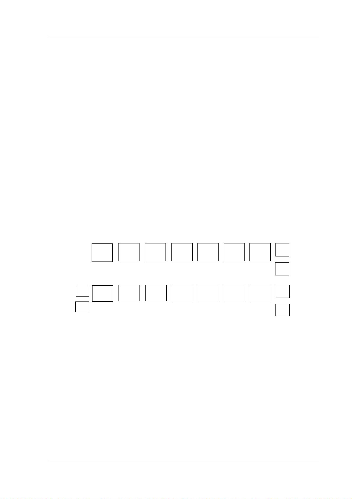
• In the MACHINE basic display of the test environment, the 1st softkey on the NC control
panel corresponds to function key F2. In all other applications, the 1st softkey corresponds
to function key F3.
Machine basic display:
[∆]
F1 [M]
Other applications:
• You can switch between test environment tasks using the standard MS Windows mecha-
nism (<Alt> + <Tab> etc.).
SK1
F2
SK1
F3
SK2
F3
SK2
F4
SK3
F4
SK3
F5
SK4
F5
SK4
F6
SK5
F6
SK5
F7
SK6
F7
SK6
F8
SK7
F8
SK7
F9
i
>
>
F1 (Help)
F10
©
Siemens AG 2001. All Rights Reserved 6FC5198-6AA70 2-3
SINUMERIK 840C OEM Version for Windows (BN)
Page 20
2 Overview and Installation
PCMCIA
h
09.01
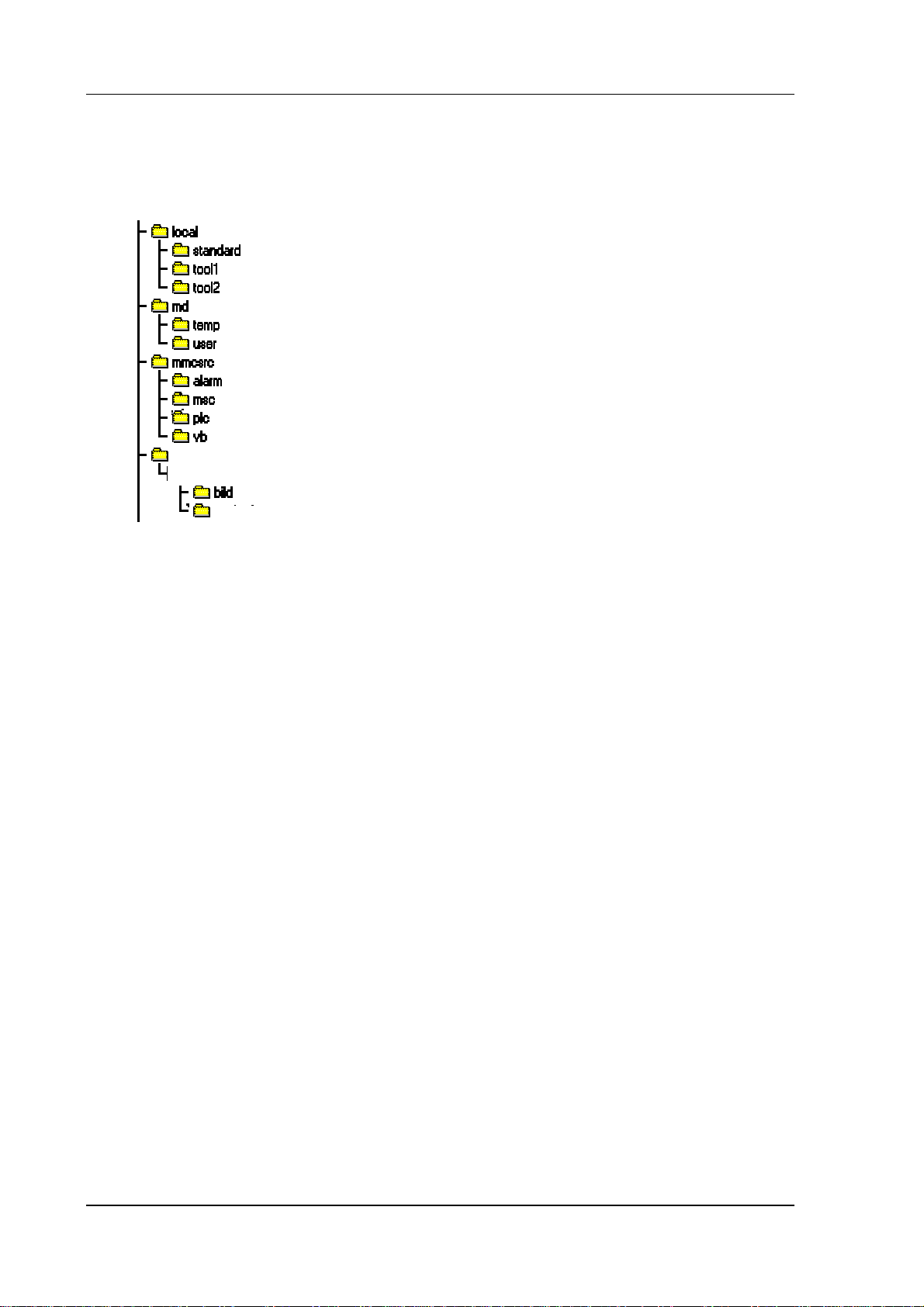
2.4 Directory structure of the OEM test environment
When you have installed the OEM test environment you will find the following directory structure on
drive C: of your hard disk:
mmcwin
—
— PC
englis
The OEM test environment contains the following subdirectories:
• Directory "local". This directory contains the workpieces that have been created
(subdirectories) together with all the files (mpf...,spf..., toa, etc.) required for machining a
workpiece. This directory is also part of the system software of the contr ol. After installation,
only the workpiece with the name "standard" exists.
• Directory "md" usually contains the machine data of the control. As no real NCK or PLC exist
in the OEM test environment, the associated subdirectories are "empty", i.e. they only contain
the obligatory "dummy" files. Both the workpieces and the directory with the machine data
can be selected and edited under the data management of the OEM test environment.
• Directory "mmcsrc" contains a number of sample programs including all the source and
resource files. These sample programs are intended to provide you with help in developing
your own applications.
The sample programs have either been developed with Microsoft Windows 3.1 SDK or
MFC 2.0 (C:\MMCSRC\MSC) or with Microsoft Visual Basic 3.0 (C:\MMCSRC\VB). They are
available either as executable *.EXE files or as entire projects with resources, source code,
libraries and header files.
The sample programs VSASER.EXE, ADVTEST.EXE and TACHO.EXE are already linked
into the OEM test environment and can be started directly from it. You will find a
description of the sample programs in Chapter 6.
• Directory C:\MMCWIN\PCMCIA contains 3 com driver floppy disks, XIRCO M driver floppies
and PC-CARD HD Patch.
• Directory C:\MMCWIN\PC contains all the basic modules of 840C OEM Version for Windows.
This directory exists both in the OEM test environment as well as in the contr ol. In addition to
the basic components such as area switchover, data management, the editor "WEdit" etc.,
this directory contains the actual DDE server (DDESRV.EXE) for linking Windows
applications to the NCK, PLC and 611D. This directory also contains a multiport RAM
simulator (MPRSIM.EXE) for PC use. You will find a description of the basic modules in
Section 3.3.
• Directory \mmcwin\pc\bild contains the machine displays that are displayed in the OEM test
environment when a machine area is called.
■
2-4
©
Siemens AG 2001. All Rights Reserved 6FC5198-6AA70
SINUMERIK 840C OEM Version for Windows (BN)
Page 21
3 System Structure of 840C
09.01
3 System Structure of 840C
3.1 Overview
The product SINUMERIK 840C OEM Version for Windows provides the machine-tool manufacturer
with a sophisticated and modern control which is used as a basis for integrating additional function
expansions and customer-specific solutions.
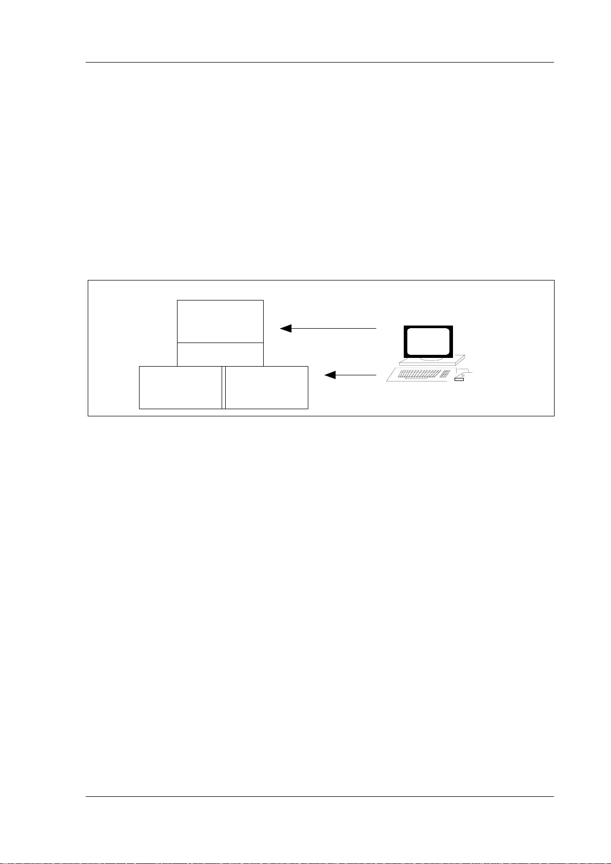
3.1.1 Hardware concept
The following hardware configuration was chosen to meet the demands for "open architecture" and
adaptability.
External
programm ing
MMC
device or
Comm unication
NCK PLC
A T-compatib le PC
Fig. 3.1: Functional st ructure of SINUMERIK 840C OEM Version for Windows
The CNC 840C control can be divided into the following three components:
MMC=PC: With this integrated AT-compatible PC with the operating system Windows for
Workgroups 3.11, the machine-tool manufacturer can make individual
adaptations and develop his own solutions on all levels of the user interface
(MMC=Man Machine Communication) including communication with the NCK
and the PLC. The AT box of central controller 3 also provides the user with open
architecture hardware.
NCK: The actual NC kernel works with a 32-bit word size and an NC memory of 1 MB.
Up to 6 spindles can be operated from its 15 servo loops. Several programs can
be executed simultaneously due to its channel structure. Data can be exchanged
with the MMC and the PLC via the DDE interface and the VDI interface. Using
program package WS800 A, machine displays can be configured in the NCK
and customized machining cycles created and the control therefore adapted to
the individual tasks of the machine tool.
PLC: The PLC section of the SINUMERIK 840C is responsible for the entire machine
control and always contained the essential know-how of the machine-tool
manufacturer. 1024 inputs and outputs, a 256-KB user memory and a
processing speed of less than 1 ms per 1000 instructions are the salient features
of the freely programmable PLC.
©
Siemens AG 2001. All Rights Reserved 6FC5198-6AA70 3-1
SINUMERIK 840C OEM Version for Windows (BN)
Page 22
3 System Structure of 840C
09.01
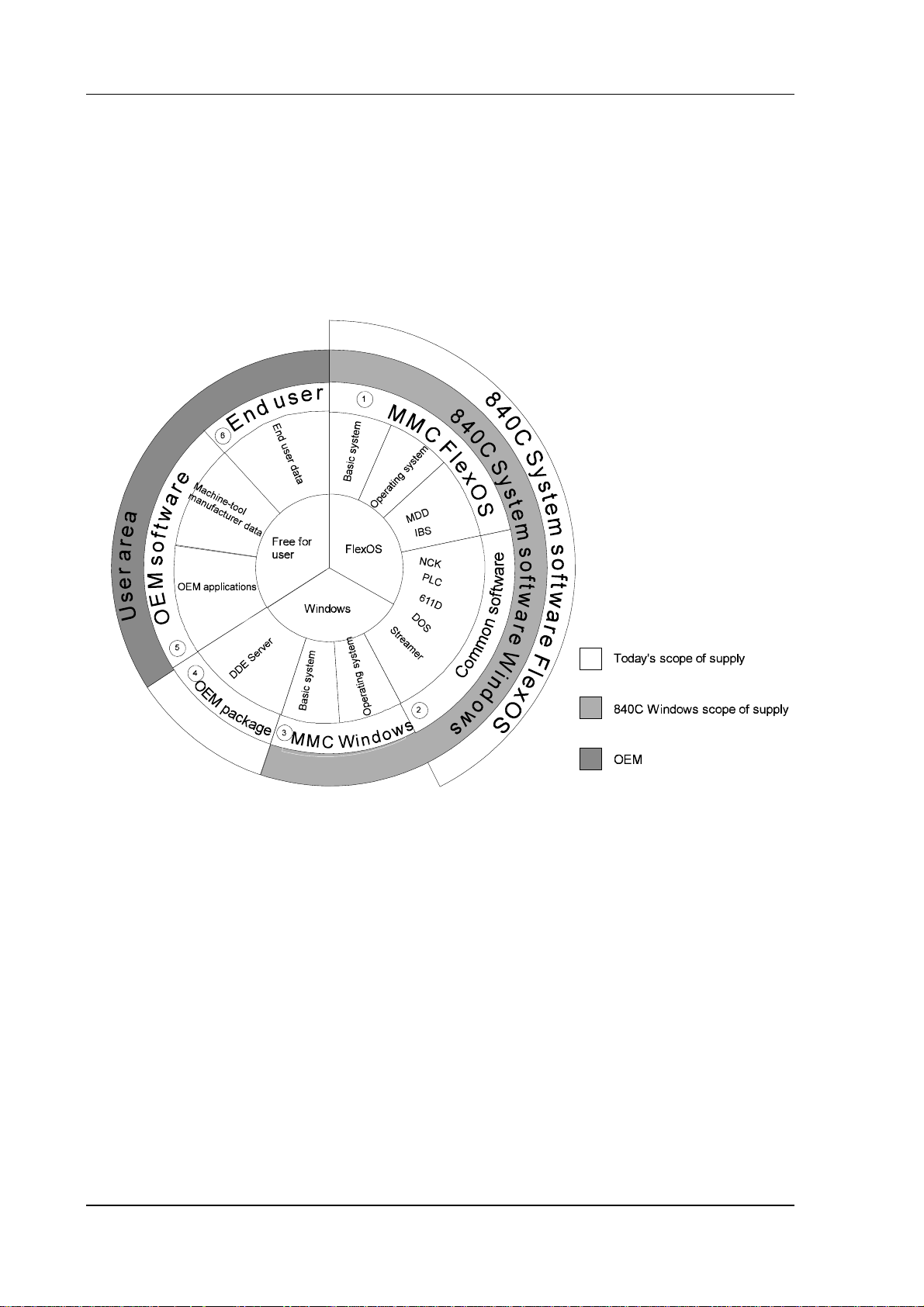
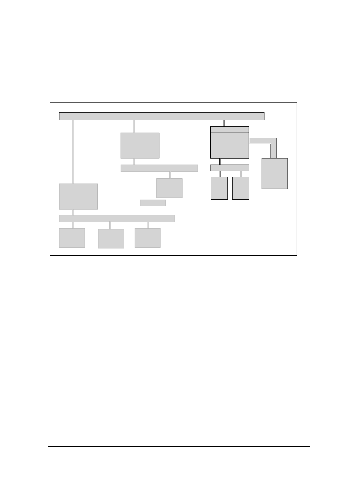
3.1.2 Software structure of the integrated PC
The system software of the CNC control 840C OEM Version for Windows comprises the 840C system
software basic version (FlexOS) which has been expanded by a Windows MMC. The OEM test
environment essentially consists of modified MMC Windows software installed on the hard disk which
enables simulation of the Windows SINUMERIK 840C interface on an external PC. The diagram below
shows the distribution of the entire control software on the hard disk.
Fig. 3.2: Main divisi on of the software on the hard disk of the 840C OEM Version for Windows
1. The installation functions (MD dialog, drive/servo installation) in the Diagnosis area can only be
executed under MMC FlexOS. The operating system FlexOS can be selected in the
backup/restore menu.
2.
Common software includes DOS, Valitek and NCK, PLC and drive software. This software r uns
with the Windows MMC without any restrictions.
The Windows MMC consists of the operating system Windows for Workgroups 3.11 and a
3.
Windows basic system (basic modules) which, like the basic version (FlexOS), is responsible for
the basic functions of the Windows control panel and operation. The user can also install the
software in the five standard languages (English, German, French, Italian and Spanish) and
switch between the individual languages.
4.
The DDE server (Dynamic Data Exchange) is the data interface to the NCK, PLC and 611D. The
DDE server is both part of the OEM package and the control software. However, it can only be
executed with the library MEMBER.DLL supplied with the OEM package.
3-2
©
Siemens AG 2001. All Rights Reserved 6FC5198-6AA70
SINUMERIK 840C OEM Version for Windows (BN)
Page 23
3 System Structure of 840C
09.01
The user area can be used both by the machine-tool manufacturer and the end user. The OEM
5.
can use the part of the hard disk that is not used by Siemens which is paid for when the MMC
Windows licence is purchased. A memory size of at least 40 MB is guaranteed. As it is possible
to integrate OEM software under Windows, space on the hard disk is provided for customized
programs that can be developed using commercially available tools.
6.
The user area can also be used for end user data such as part pr ograms, measurement data,
order data, MDA/PDA data etc.
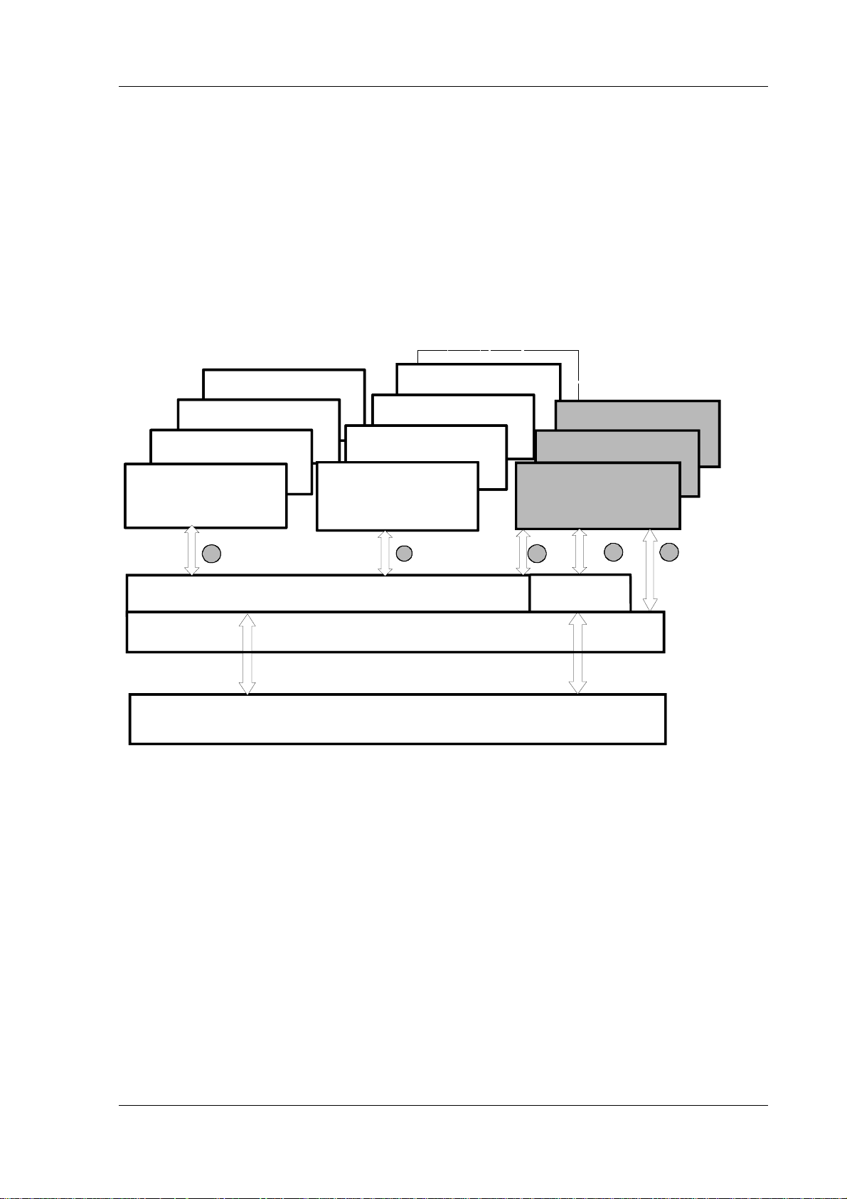
The individual operating system components, as well as the Siemens basic modules and the OEM
applications can interact as shown below and exchange information with the NCK/PLC and the 611- D.
Fig. 3.3. clearly shows the interaction between the Windows system software and the basic modules
and OEM applications.
NCK/PLC service
NCK programming
Parameters
Machine operation
1
V24 parameterization
Data management
Area switchover
235
WEdit
Basic system
DOS / WINDOWS
NCK / PLC / 611-D
Fig. 3.3: Interaction bet ween M M C Wi ndows and OEM applications
OEM appl.
< . . . . > . exe
4
DDE
server
1. The machine displays created in the NC kernel with WS800 A are passed directly to the user
interface via a graphics converter (NCK task), i.e. the operator receives the information directly
from the NCK/PLC and 611-D. Conversely, (nearly) all the entries made via the keyboard on the
control panel or the MF2 keyboard are passed onto the NCK.
2.
In addition to the NCK task, other Siemens basic modules carry out numerous functions in the
MMC area. The area switchover is therefore used to start additional applications and the data
management to manage the files on the hard disk and to transfer data between the MMC and
the NCK or peripheral device.
3.
The OEM applications like the Siemens applications (e.g. machine operation, parameters, etc.)
are initiated via the area switchover. Some of the basic modules also contain special function
calls (e.g. workpiece transfer via serial interface) which can also be used by OEM applications.
The OEM applications can be operated in the usual way via the operator panel or keyboard.
©
Siemens AG 2001. All Rights Reserved 6FC5198-6AA70 3-3
SINUMERIK 840C OEM Version for Windows (BN)
Page 24
3 System Structure of 840C
09.01
Data on NCK, PLC, 611D is accessed using the DDE server via the DDE interface defined by
4.
Microsoft. This interface is supported by nearly all Windows programs (EXCEL, WORD, etc.) and
development tools (MS-Visual Basic, Visual C++, etc.) and guarantees a high degree of
development safety and stability due to its fixed definition and widespread use.
5.
OEM applications can also directly access services in the DOS/Windows oper ating system. File
manager, printer, Windows API (Windows Application Programmers Interface), etc. calls can be
used in the usual way.
3.1.3 Basic modules
The MMC Windows basic system together with the operating system are r esponsible for operation of
the integrated PC. The MMC Windows basic modules and the OEM test environment are largely
identical. All the standard modules have a compatible structure and a uniform appearance which can
be modified by making entries in the initialization files. Basic modules that run in the background (e.g.
multiport RAM driver, keyboard driver, DDE server etc.) are configured in such a way that they do not
appear in the task list. This ensures that the user only accesses applications that he can see in the task
list.
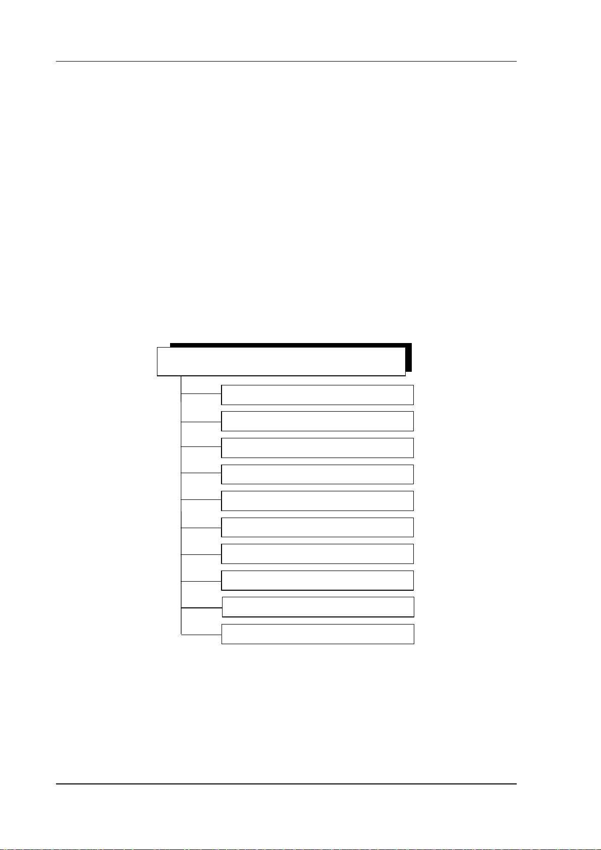
The following diagram provides an overview of the most important modules in the basic system
840C WINDOWS Basic system
Start up
Area switchover
Graphics converter (NCK task)
Data management ASCII editor
V24 parameterization
Alarm module
NCK/PLC communication
Softkey manager
Keyboard driver
Backup/Restore
Fig. 3.4: Basic system OEM Version for Windows
• The start-up module (AUTOEXEC.BAT, REG_AUTO.CFG) organizes the loading of the MPR
server, the booting of the PLC/NCK and 611-D software. The user can also define in the
initialization file C:\MMCWIN\LOAD840C.INI which user files are to be transferred to the NCK
during start-up.
3-4
©
Siemens AG 2001. All Rights Reserved 6FC5198-6AA70
SINUMERIK 840C OEM Version for Windows (BN)
Page 25

3 System Structure of 840C
09.01
• Individual applications can be started by the operator via softkey with the area switchover
(REGIE.EXE) which replaces the Windows program manager. It is activated via the data area
key. As far as the area switchover is concerned, the Siemens areas, "Machine", "Par ameter", ...,
are ordinary applications.
The menu line and the entries in the associated pull-down menus including the application to be
initiated (*.EXE files) can be freely defined in the initialization file (REGIE.INI). Applications can
also be protected with a password, keyswitch position and cycle disable. The area switchover is
preconfigured by Siemens and can be changed as necessary (e.g. removing the Machine area
and adding OEM applications). It can be operated either via the control panel keys, softkeys or
mouse.
• NCK task (NCKTASK.EXE) groups together the entire control of the NCK. Th is includes both the
display of graphic information that is processed in the NCK area as well as the transfer of
keyboard entries to the NCK. NCK task is also responsible for managing the current menus of
the various data areas of the NCK. In the OEM test environment where ther e is no link to an
NCK, NCK task visualizes machine displays that are stored on the hard disk.
• The data manager (DATENMAN.EXE) contains a user interface for transferring files between the
MMC, NCK, diskette drive and serial interface. A workpiece manager and an editor "WEdit"
(WEDIT.EXE) with which part programs can be edited directly in the NCK memory are also
provided.
With the workpiece manager it is possible to integrate network drives, making transparent
selection of workpieces that are stored on a remote computer possible. "Part program execution
from the hard disk or network" is also implemented. Files can also be edited directly in the NCK
memory with the editor.
• With the Parameterization V24 module (PAR_V24.EXE), serial interfaces can be par ameterized
for the transmission of data in tape format. Up to 10 interface settings can also be managed.
• The alarm module (ALARM.EXE) accepts alarms and messages from the NCK/PLC/drive,
visualizes them in the alarm or message line and lists the current alarms and messages in the
alarm window. The position at which the alarm is displayed on the screen is defined in the alarm
text database. An OEM application can obtain the current active alarms and messages via the
Windows DDE mechanism (Dynamic Data Exchange) and initiate its own.
• The NCK/PLC communication essentially consists of the DDE server (DDESRV.EXE) and the
MPR server (SERVER.EXE) which allow the modules described above and the OEM
applications to exchange data with the NCK/PLC and the 611D. In the OEM test environment,
the multiport RAM server is replaced by an MPR server simulator (MPRSSIM.EXE).
• The softkey manager (SOFTMAN.EXE) displays the menu line of Windows applications and the
buttons of non-system modal dialog boxes on the horizontal softkey bar. It is thus also possible
to operate any Windows application via softkey.
• The keyboard driver (KYRU.EXE) converts signals coming from the 840C operator panel into
codes which can be evaluated by Windows or DOS. This same thing happens when a full MF2
keyboard is connected to the operator panel. A keyboard can only be connected to the central
controller for OEM servicing because of the lack of EMC of the keyboard connection.
The user can also freely assign various keys on the NC operator panel.
• Data can be saved and read back in via the Valitek streamer or via PC link as on the 840C Basic
Version. The streamer is connected to the parallel interface of the MMC CPU module. You must
close Windows and return to the MS DOS level to operate the streamer.
©
Siemens AG 2001. All Rights Reserved 6FC5198-6AA70 3-5
SINUMERIK 840C OEM Version for Windows (BN)
Page 26
3 System Structure of 840C
09.01
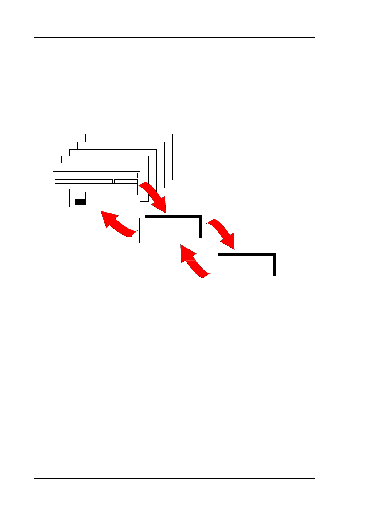
3.1.4 NCK / PLC / SIMODRIVE 611-D interface
Data/files of the NCK/PLC/611D are accessed via the DDE interface (Dynamic Data Exchange) defined
by Microsoft for Windows applications. The DDE server collects the data and makes them available to
the applications. The functions "POKE" (write data), "REQUEST" (read data) and "EXECUTE"
(commands for file transfer) are implemented. The function "ADVISE" is also implemented for the PLC.
Data exchange with standard Windows programs such as Excel, Visual Basic, etc. is possible via this
interface. The DDE server can access, for example, machine data, setting data, PLC data blocks, part
programs and current values.
. . .
BORLAND C++
VISUAL C++
VISUAL BASIC
E X C E L
1
= NC DDE NCK PLC ! NC_0X125_1_1_2_2_0
2
3
AB
100
Speed
50
spindle
0
Read and write
data, programs
DDE server
NCK/PLC/611-D
Fig. 3.5: Data exchange via DDE server
The DDE server converts the data request into an I code protocol and passes it on to the NCK. There,
a software module sends the requested data to the DDE server.
Two function blocks exist in the PLC, FX74 (read data from DDE server and write to a data block) and
FX73 (read data from a data block and write to the DDE server). The user can fr eely select the for mats
and the protocols. For this, he must write a function block that reads out the data with the help of FX74,
interprets them and writes back the requested data with FX73.
Service and drive data can be accessed for the SIMODRIVE 611-D. The DDE server is only used for
data exchange and is not a control interface.
You will find a detailed description of the DDE server and the I code interface with its various features
in Chapter 5 and Appendix A1.
3-6
©
Siemens AG 2001. All Rights Reserved 6FC5198-6AA70
SINUMERIK 840C OEM Version for Windows (BN)
Page 27
3 System Structure of 840C
09.01
3.2 Hardware configuration
You will find additional information on this subject in the SINUMERIK 840C documentation:
Interface Part 2, Connection Conditions.
The hardware of the 840C OEM Version for Windows is based on the 840C Basic Version.
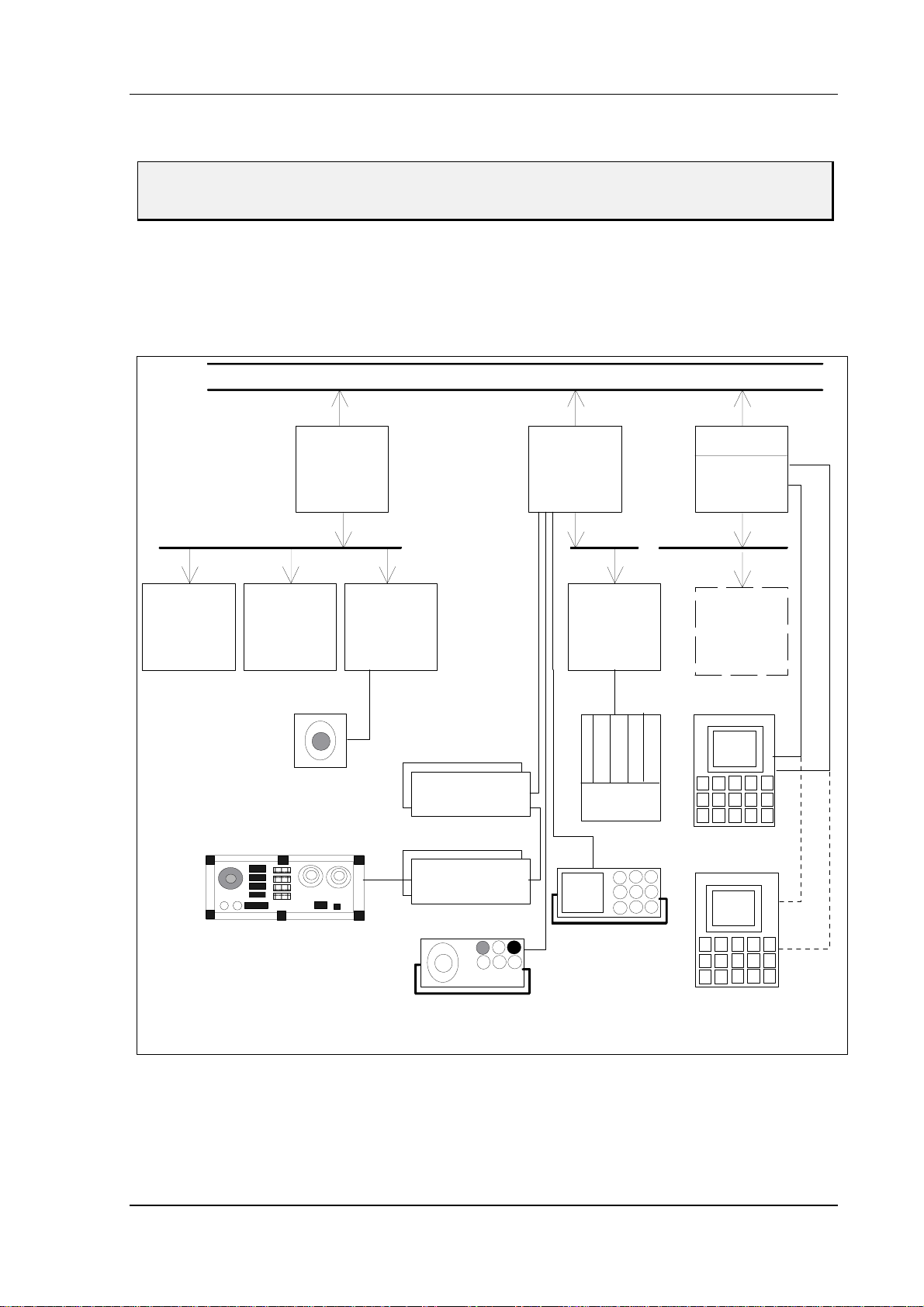
3.2.1 Brief description of hardware
The SINUMERIK 840C OEM Version for Windows is a modular control with the following structure:
Link bus
Dual Port
NCK CPU
PLC CPU
MMC CPU
Servo
loops
NCK bus bus busPLC
Computer
link
Handwheel
CSB INT. EU
DMP mod.
DMP mod.
Handheld unit
SIMATIC EU
PG
AT96
AT box
OP
2nd
OP
RGB
RS232
Fig. 3.6: Block diagram of SINUMERIK 840C OEM Version for Windows
©
Siemens AG 2001. All Rights Reserved 6FC5198-6AA70 3-7
SINUMERIK 840C OEM Version for Windows (BN)
Page 28

3 System Structure of 840C
The system uses the following hardware components:
• NCK CPU
- NCK CPU 486 DX 33MHz or 486 DX2 66MHz with 4 and 8 MB RAM,
486 DX4 66MHz with 8 MB RAM
486 DX4 100 MHz with 8 MB RAM
- Servo loops
up to 30 servo loops (axes/spindles) analog and digital drive interfaces,
max. 2 electronic handwheels.
- Computer link
computer link via RS 232C (V.24), SINEC H1 or MAP 3.0
- Central service board (CSB)
central monitoring functions,
handwheel inputs,
NC inputs
- 230V AC / 24V DC power supply (occupies three slots)
• PLC
- PLC CPU 135 WD
80186 / 16 MHz
PLC coprocessor
MPC interface for distributed machine I/Os
RS 232C (V.24) interface to PG
rapid interrupt inputs
- Interface EU, 16-bit
16-bit link to SIMATIC EU (IM314)
- Distributed machine I/Os
standard DMP
compact DMP
machine control panel
- In 329
L2-DP Profibus
09.01
•••• MMC
- MMC CPU (version B), 486 SX 33 MHz, 486 DX 33 MHz, 486 DX2 66 MHz
with 8 or 16 MB RAM
2 serial interfaces (operator panel connection or freely assignable)
Centronics interface to streamer
MF/2 keyboard interface
- Interface MMC
Connection for FD-E2 3.5" diskette drive
2 serial interfaces
PCMCIA slot
- Operator panel versions
9.5/10 inch slimline operator panel monochrome incl. NC keyboard
9.5/10 inch slimline operator panel color incl. NC keyboard
14 inch monitor with separate NC keyboard
• AT box with 3 slots
3-8
©
Siemens AG 2001. All Rights Reserved 6FC5198-6AA70
SINUMERIK 840C OEM Version for Windows (BN)
Page 29
3 System Structure of 840C
09.01
3.2.2 Integrated PC
The PC is integrated into the system and is a system component that communicates via the internal
link bus.
Visualization and communication tasks and database functions are chiefly performed on this industrial
PC.
SINU M E RIK 840 C
Link bus
Multiport RAM
MMC
PLC CPU
CPU
(SBC)
NCKCPU
NCK local bus
Servo
loops
Fig. 3.7: MMC in the hardware of the 840C
Computer
link
PLC local bus
Int. EU
MSTT
CSB
AT 96
INT
MMCATBox
Operator
panel
The PC integrated in the 840C OEM Version for Windows provides all the functions of an AT
motherboard. The entire set of chips of an AT is integrated on one printed circuit board, which gives
rise to the name SBC (single board computer). The SBC is an industry-standard and noise-fr ee ver sion
of an integrated industrial PC. It is linked to the internal SINUMERIK bus via a dual-por t RAM and via
this link is able to exchange data with the NCK, PLC and SIMODRIVE 611-D.
An MMC interface module can be slotted into the central rack directly next to the MMC CPU module via
the AT96 bus. This module has two additional serial interfaces, two PCMCIA slots (type II) and a floppy
bus extension for connecting diskette drive FD-E2.
Central controller 3 also contains an AT box whose ISA bus is linked to the AT96 bus. A maximum of 3
standard 16-bit PC cards can be slotted into this AT box, providing the user with many options for
connecting peripherals (networking via standard PC modules) or integrating existing external solutions
directly to the control (measuring computer for quality assurance).
In contrast to a standard PC, however, the integrated SBS of the SINUMERIK 840C does not have a
loudspeaker.
©
Siemens AG 2001. All Rights Reserved 6FC5198-6AA70 3-9
SINUMERIK 840C OEM Version for Windows (BN)
Page 30
3 System Structure of 840C
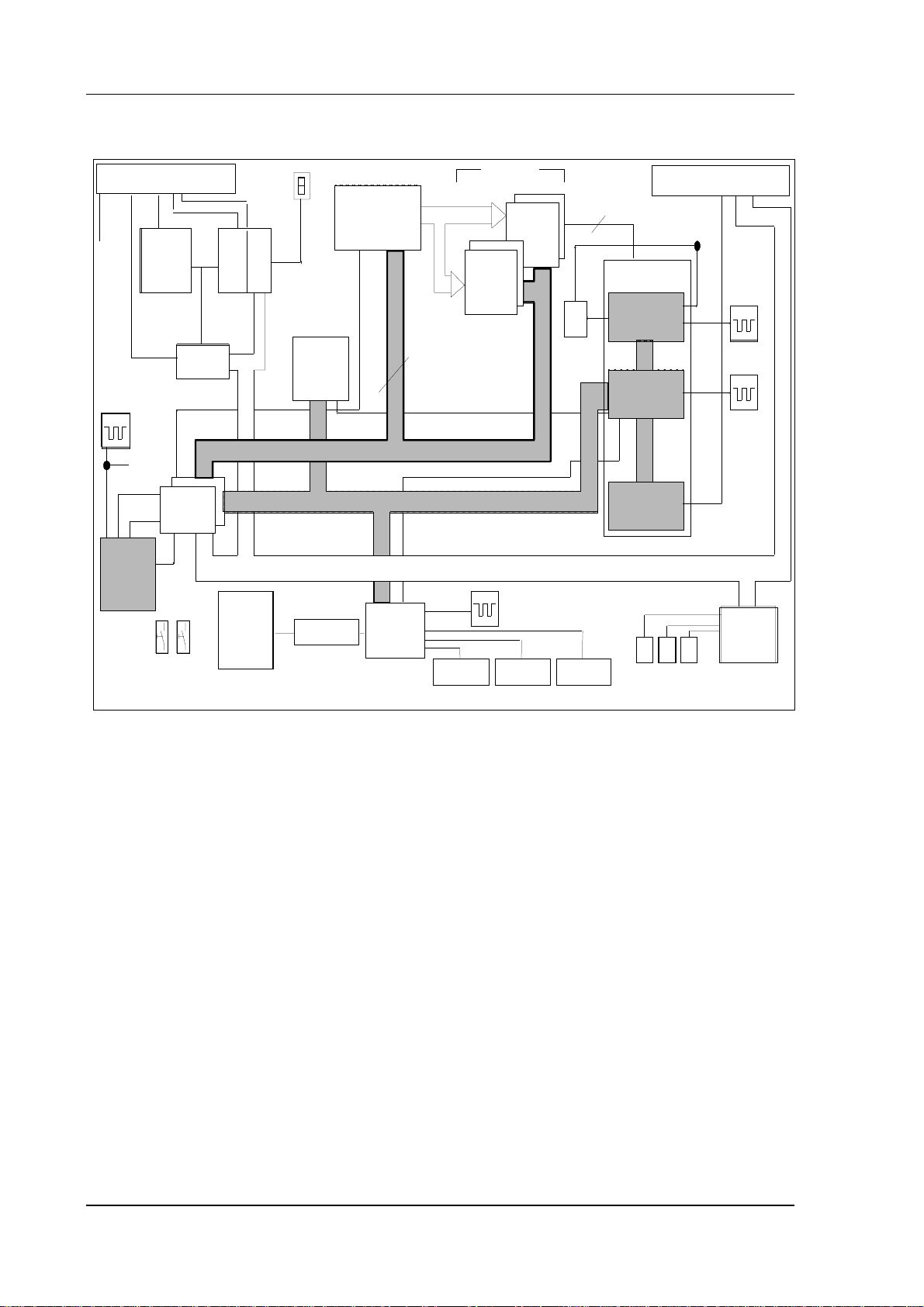
3.2.2.1 Block diagram
09.01
32K
Status
EPROM
MCU
mem or y c ontr ol
BIOS
64 Kx8
ED BU S (32 bit)
XD BUS (8 b it)
+5V
+15V
BATT
U
66 MHz
80486
Link bus X11
DPR
contr.
66 MHz
32 bit
CD BUS
Dual port
RAM
32K
Stat . cont.
2 DPUs
data path
CPU
NMI
Winchester
drive
RESET
IDE interface
Fig. 3.8: Block diagram of the MMC 486 CPU module
Com bo
16 bit
SD BUS (16 bit)
X 111
RS232/TTY
max. 32 MB
DRAM
x3 6
bank 0
18.432 MHz
*with adapter
DRAM
x36
bank 1
X 121 X 1 32
4 bit parit y
: 2
Keyboard i nterfaceRS232/RS42 2*
ATU
TIMING
control
PERIPHERA LS
RTC
AT BUS I /F
R G B
Video interface
AT96 Bus X21
66 MHz
14.3181 MHz
32.768 kHz
VGA
graphic
un it
3.2.2.2 Processor 80486
- External 33MHz clock, internal 33 or 66 MHz clock
- 100% software-compatible with 80386
- 32-bit data bus
- 4 GB linear address space
- Real and protected mode
- Integrated floating point unit
- Integrated 8 KB cache
3.2.2.3 System memory
- Two slots with x36 organized SIM modules
- Max. 16 MB dynamic memory, 8 MB in the basic version
- Modifiable DRAM parameters in the set-up
- 4 bit parity monitoring
- EMS (version 4.0) support
- Shadow RAM function for BIOS
3-10
©
Siemens AG 2001. All Rights Reserved 6FC5198-6AA70
SINUMERIK 840C OEM Version for Windows (BN)
Page 31

3 System Structure of 840C
09.01
The following diagram shows the distribution of the entire system memory of the MMC CPU:
64 KB BIOS
(after reset)
Extended
DRAM area
64 KB BIOS
FFFF000:FFFF
XF000:FFFF
10000:0000
F000:0000
32 KB SRAM link memory
32 KB SRAM link memory
Video BIOS
E000:0000
D000:8000
D000:0000
C800:0000
C000:0000
Video memory
A000:0000
640 KB DRAM
0000:0000
Fig. 3.9: Memory dist ri bution of the MMC CPU module
• Like AT-compatible PCs, the working memory area of the MMC CPU features the memory
distribution typical of an ISA system (Industry Standard Architecture)
• A 64 KB static RAM is used for physically linking the link bus to the NCK/PLC and the
SIMODRIVE 611-D. This multiport RAM features the following:
- Unbuffered
- 64 KB link memory to the SINUMERIK link bus (32k/32k)
- Memory area: D000:0000 - D000:7FFF (link area between NCK and PLC,
can only be read from the MMC)
D000:8000 - D000:FFFF (link to link bus)
- Interrupts 10 and 15 are assigned for the link to the NCK/PLC and the SIMO-
DRIVE 611-D.
©
Siemens AG 2001. All Rights Reserved 6FC5198-6AA70 3-11
SINUMERIK 840C OEM Version for Windows (BN)
Page 32

3 System Structure of 840C
09.01
3.2.2.4 Mass storage medium
The MMC CPU uses a hard disk drive as mass storage medium. The link is provided by the IDE
interface. The MMC CPU is currently supplied with a 540 MB/1 GB disk as standard.
• Replacement of the hard disk is automatically detected by the BIOS and entered in the
set-up
• Integrated PC/AT controller
Note:
Reducing disk accessing during the running operation of the control.
When booting the control, the basic system software is being loaded into the MMC user memory
(RAM). If no further additional operations are carried out, the MMC module has the following remaining
memory:
Memory configuration of MMC CPU Reported free remaining memory
8 MB
16 MB approx. 11 MB
These values specifically apply to software version 6.1 and may vary with other software versions.
This means that MMC basic software requires no SWAP file so that the user may switch off relocating
of data to the hard disk (swapping) by setting the SWAP file size to 0 KB. OEM users setting up their
own applications and running them on the MMC have to ascertain how much memory capacity the
whole system (basic and application) requires and then decide if switching off of the SWAP file makes
sense.
approx. 3 MB
3.2.2.5 Watch Dog
This module is responsible for monitoring and has the following performance data:
• Not programmable, monitoring time of 1.6 s (fixed)
• Enable and trigger via status register 0
3.2.2.6 VGA video graphic unit
• AT bus interface
• Resolution and video timing programmable
3.2.2.7 Electrical and mechanical data
• Required voltage: +5V, +/-15V
• Format: Double-height Eurocard
• Module height: 40 mm (incl. hard disk drive)
3.2.2.8 PCMCIA software support
The two PCMCIA 2.0 slots on the interface MMC module are not directly supported in the standard
version by either the BIOS or the Windows operating system.
Manufacturers of PCMCIA cards usually include the drivers in the scope of supply of their product so
that these cards can also be used in the MMC interface module. Care should however be taken when
performing installation with typical PCMCIA default settings (I/O address 300, interrupt 10) as interrupt
10 (cf. 3.2.2.10) is already used by SINUMERIK 840C.
3-12
©
Siemens AG 2001. All Rights Reserved 6FC5198-6AA70
SINUMERIK 840C OEM Version for Windows (BN)
Page 33

09.01
3 System Structure of 840C
3.2.2.8.1
The two PCMCIA 2.0 slots on the interface MMC module are not directly supported in the standard
version by either the BIOS or the Windows operating system.
Software installation:
− Floppy disk drive, external keyboard,
− WfW 3.11 installation floppies (C:\WININST) see also:
− 3Com driver floppy 2 (C:\mmcwin\PCMCIA\3com2.exe of test environment)
Installation of a 3Com 10 MBps LAN PC Card, type 3CCE589EC
SINUMERIK 840C
Installation and Start-Up, Description of Differences
OEM version for Windows™
Installation and Start-Up Guide
Manufacturer Documentation
1.2.3 Installation of Windows resources
must be available. You do not yet need to insert the network adapter.
Set the password, open the File Manager and select File/Run and enter "progman" to
1.
open the Program Manager. In this screen, open Windows Setup and select
Options/Change Network Settings.
2.
When the Network Setup dialog box opens, select the networks.. button and set Install
Microsoft Windows Network in the box which opens next. Close this again by selecting
the Ok button.
3.
By selecting button sharing.. in the Network Setup box, you can open a screen for
setting access rights which allow other computers to access the control.
4.
Select the drivers.. button in the Network Setup box and then button Add-Adapter in the
next box. A list of available drivers will be displayed. Select option unlisted network
adapters to install the 3Com driver. The software is installed from the second (!) floppy
(we are using Version 5.5, oemsetup.inf in A:\).
5.
Select and set Setup:
− Interrupt 11 (as this is automatically assigned: Call Setup a second time after installation
and change to interrupt 11 or, after installation, set directly in protocol.ini, section [ELPC3]
entry INTERRUPT=11)
− Base I/O 300H
− BaseMemory automatic or unused
6.
Select the Close button to exit the Network Setup box.
Enter the user, group and computer name.
7.
8.
The MS Windows Network application is then installed by the Windows Setup routine
(use the browser to set path C:\WININST for each of the requested WfW 3.11 installation
floppies to install files NDIS.386 and WFWNET.DRV).
9.
When the Windows Setup routine asks for the manufacturer driver, select Elpc3.dos on
the second floppy, path A:\Mslanman.dos\Drivers\Ethernet\Elpc3, e.g. using the browser.
10.
Before restarting your computer, make the following changes using the Notepad text
editor:
− Set PCMCIA_ENABLER=YES in section [ELPC3] of file \windows\protocol.ini
so that the CardServices are not used.
In the same file, insert a comment semicolon in front of the SLOT line.
©
Siemens AG 2001. All Rights Reserved 6FC5198-6AA70 3-13
SINUMERIK 840C OEM Version for Windows (BN)
Page 34

3 System Structure of 840C
;SLOT = 1
because 1 is not the number for slot A (slot A will be addressed if you insert a comment
semicolon)
− Change the following line in file c:\config.sys to
device=C:\DOS\EMM386.EXE NOEMS X=C000-DFFF
− Change the following line in section [386enh] of files c:\windows\system.ini and
c:\mmcwin\pc\system.ini to
EmmExclude=C000-DFFF
No other memory manager may have access to the memory array used by the PCMCIA
network card!
− Below are some of the settings which must be made in section [386Enh] of file system.ini
to avoid hardware conflicts:
COM3Irq=5
COM3Base=03E8
COM4Irq=9
COM4Base=02E8
11.
Power down the control and switch off.
Hardware installation:
09.01
− Set DIP switches on the interface MMC to the standard 00010010 or deactivate COM3 and COM4
with 1 000 0000.
− Insert card, e.g. in socket A of the interface MMC, with the front end of the card labeled Etherlink III
on the right, i.e. you insert the card with this label upside down.
Note
If a 3Com network card is installed on a SINUMERIK 840C OEM Version for Windows control
system, you may find that the computer stops booting at the "net start" command when you
restart it warm. If this happens, switch it off and then on again so that it can boot correctly.
Note
After you have installed the software successfully, you must make the change that was made in file
c:\config.sys in file c:\config.emm as well. This will ensure that the network installation remains
operable even when the computer is rebooted from Windows to FlexOS and vice versa!
To ensure the changes remain valid when the software is updated, they must be made in the files
marked by an X in the following table:
Change
C:\TOOLS X
C:\TOOLS\MSD X X X X X
C:\TOOLS\DRD X
à c:\windows\net start device=C:\DOS\EMM386.EXE NOEMS X=C000-DFFF
AUTOEXEC.BAT CONFIG.
SYS EMM DRD FLX
C:\ X X X
Make a new backup after you have installed the network for later restore purposes!
3-14
©
Siemens AG 2001. All Rights Reserved 6FC5198-6AA70
SINUMERIK 840C OEM Version for Windows (BN)
Page 35

09.01
3 System Structure of 840C
3.2.2.8.2
– Floppy disk drive, external keyboard,
− WfW 3.11 installation floppies (C:\WININST) see also:
− XIRCOM driver floppy (C:\mmcwin\PCMCIA\XIRCOM2.exe of test environment)
− Set the password, open the File Manager and select File/Run and enter "progman" to open the
− When the Network Setup dialog box opens, select the networks.. button and set Install Microsoft
− By selecting button sharing.. in the Network Setup box, you can open a screen for setting access
− Select the drivers.. button in the Network Setup box and then button Add-Adapter in the next box.
− Select and set Setup: Interrupt 11, Base I/O 300H, Memory C8000
− Load driver, insert floppies if requested or set path C:\WININST using the browser.
− Add the following settings in section [XIRCMAC] of file \windows\protocol.ini:
Installation of an Xircom RealPort Ethernet 10/100+Modem 56, type REM56G-100
SINUMERIK 840C
Installation and Start-Up, Description of Differences
OEM version for Windows™
Installation and Start-Up Guide
Manufacturer Documentation
1.2.3 Installation of Windows resources
must be available. You do not yet need to insert the network adapter.
Program Manager. In this screen, open Windows Setup and select Options/Change Network
Settings.
Windows Network in the box which opens next. Close this again by selecting the Ok button.
rights which allow other computers to access the control.
A list of available drivers will be displayed. Select option unlisted network adapters to install the
Xircom XCEM NDIS 2.01 RealMode driver. The software is installed from the driver floppy (we are
using Version 2.31).
− To deactivate the modem function: NOCOM
− To prevent various checks from being performed when the driver starts: NOCHECK
Important:
It is essential that these checks are made during start-up. For this reason, do not use option
NOCHECK to begin with. We experienced the following problem: The card driver booted
properly after a cold start but, when the computer was then warm started (e.g. after language
switchover or Ctrl-Alt-Del), the message: "The selected memory segment is in use" appeared.
The card then ceased to boot. When we set option NOCHECK, the driver booted properly after
a warm start and the network operated perfectly. Xircom thinks that this solution is acceptable
and could not offer any alternative.
− You can add the line LINESPEED=100 or LINESPEED=10 as an option. This forces the card
to transmit at 100 Mbps or 10 Mbps. If the card cannot transmit this fast because, for example,
the transmission partner is not capable of this speed, the network will crash. If you leave out
the line altogether, the fast possible transmission speed will be selected automatically.
©
Siemens AG 2001. All Rights Reserved 6FC5198-6AA70 3-15
SINUMERIK 840C OEM Version for Windows (BN)
Page 36

3 System Structure of 840C
09.01
− Change the following line in file c:\config.sys to
device=C:\DOS\EMM386.EXE NOEMS X=C000-DFFF
Change the following line in section [386enh] of files c:\windows\system.ini and
c:\mmcwin\pc\system.ini to
EmmExclude=C000-DFFF
(No other memory manager may have access to the memory array used by the PCMCIA network
card!)
Hardware installation:
− Set DIP switches on the interface MMC to the standard 00010010 or deactivate COM3 and COM4
with 1 000 0000
− Insert card in socket A of the interface MMC, socket B cannot be used because of size of card
− Cabling, use of a hub:
The partner computers can be directly connected (via a twisted-pair cable). They can also be linked
via a hub (but then not using a twisted-pair cable). Xircom requires a hub to be connected between
the partners both with normal peer-to-peer connections and for transmissions at 100 Mbps.
Judging by our own experience, we could have managed without a hub (an opinion shared by our
internal company network hotline). Using a hub does not create any particular problems.
− To achieve the maximum transmission speed of 100 Mbps, you need - as mentioned above -
suitable partners. We used, for example, a 3Com Fast Etherlink XL 10/100 Mb TX Ethernet
adapter in the PCI slot of a Win95 PC. In its installation or configuration routine, you can select
10 Mbps, 100 Mbps or Automatic (highest possible) as the media type. In a backup test on a
2.98 MB file, the maximum configuration requires a good 5 seconds and approximately 55 seconds
at 10 Mbps. The hub has no effect on the transmission speed.
Note
After you have installed the software successfully, you must make the change that was made in file
c:\config.sys in file c:\config.emm as well. This will ensure that the network installation remains
operable even when the computer is rebooted from Windows to FlexOS and vice versa!
To ensure the changes remain valid when the software is updated, they must be made in the files
marked by an X in the following table:
Change
C:\TOOLS X
C:\TOOLS\MSD X X X X X
C:\TOOLS\DRD X
Make a new backup after you have installed the network for later restore purposes!
à c:\windows\net start device=C:\DOS\EMM386.EXE NOEMS X=C000-DFFF
AUTOEXEC.BAT CONFIG.
SYS EMM DRD FLX
C:\ X X X
3-16
©
Siemens AG 2001. All Rights Reserved 6FC5198-6AA70
SINUMERIK 840C OEM Version for Windows (BN)
Page 37

09.01
3 System Structure of 840C
3.2.2.8.3
Data backup using the PCMCIA card hard disk
The 840C OEM Version for Windows Package 6.4 contains a self-extracting file (c:\mmcwin\PCMCIA\
PCCARDHD.exe). This file is a PC card patch which can be uploaded to a SINUMERIK 840C control
with OEM Version for Windows via a PC link. The SW is installed by unpacking the file. The patch is
then integrated in the backup menus as the control system boots to enable access to a PC card Hard
Disk inserted in the PCMCIA slot. The patch is compatible with 840C OEM Version for Windows, SW
version 6. Controls with older SW installed must be upgraded beforehand with TOOLS > Version 6.7.4!
The PC card HD patch expands the backup menus (Installation and Start-Up Guide, Subsection 1.6.6
Backup/FlexOS pages 1-53) as follows.
Menu option Data Area, Diagnosis, Backup/FlexOS causes the control to end MS-Windows and drop to
the MS-DOS level. The following menu is then displayed:
Main menu
SIN840C-Windows
Copyright (c) Siemens AG 1997 - 1998. All rights reserved.
Main menu SIN840C-Windows:.......
=================================
1. Restore/Backup/Install/Uninstall
2. Boot MMC-Flexos
3. Extended functions
4. Calibrate display
5. Check and reorganize hard disk (with system restart)
6. Perform a surface scan of hard disk
0. End ...reboot MMC-Windows
================================
Enter your Choice...:=[1,2,3,4,5,6,0]?
Fig. 1-25: Main menu of 840C Windows (SW 6. 3)
1. Restore/Backup/Install/Uninstall
By selecting 1, you can go to menu "Restore/Backup/Inst./Uninst." (Fig.
1-26). If PC Card HD is set, you go to the menu for "Restore/Backup" for the
PC card Hard Disk (Fig. 1-26.1).
Restore/Backup/
Inst./Uninst.
Note
If PC card HD is set as the device, but no PC card HD hard disk is inserted in the
PCMCIA slot, you go to menu "Set device type" (Fig. 1-29.1).
Copyright (c) Siemens AG 1997. All rights reserved
Restore/Backup/Inst./Uninst. - Device PST-160
===================================================
1. Backup system (all files on disk to tape)
2. Restore system (all files on tape to disk)
3. Backup user data...
4. Restore user data
5. Backup INI-files (all files *.ini on disk to tape)
6. Restore INI-files... (all files *.ini on tape to disk)
7. Set I/O device...
8. Uninstall/Install/Unpack...
9. Free data transfer via PC-Link...(Attention!!!)
0. END...
=================================================
Enter your choice...:=[1,2,3,4,5,6,7,8,9,0]?
Fig. 1-26: Restore/Back up/ Install/Uninstall menu
7. Set I/O device...
By selecting 7, you go to the extended menu "Set device type" (Fig. 1-29.1).
8. Uninstall/Install/Unpack...
If the PC card HD patch is installed, but PC-CARD HD is not set as the
device, you go to the extended "Uninstall/Install/Unpack" (Fig. 1-30.1) menu
when you select 8.
©
Siemens AG 2001. All Rights Reserved 6FC5198-6AA70 3-17
SINUMERIK 840C OEM Version for Windows (BN)
Page 38

3 System Structure of 840C
09.01
Restore/Backup for
PC Card Hard Disk
Copyright (c) Siemens AG 2000. All rights reserved
Restore/Backup - Device PC-Card HD
===================================================
1. Backup system (system on disk to PC-Card HD)
2. Restore system (system on PC-Card HD to disk)
3. Backup user data... (user data on disk to PC-Card HD)
4. Restore user data (user data on PC-Card HD to disk)
5. Backup INI-files (Ini files on disk to PC-Card HD)
6. Restore INI-files...(Ini files on PC-Card HD to disk)
7. Set I/O device...
8. Pack/Unpack/Delete...
9. Create a boot disk for PC-Card HD
0. END...
=================================================
Enter your choice...:=[1,2,3,4,5,6,7,8,9,0]?
Fig. 1-26.1: Restore/Backup menu
1. Backup system
The option Backup System dumps all data from the hard disk in the control
system to the PC card Hard Disk. All the system software and user data are
backed up.
IMPORTANT
When you back up data, any backup which already exists on the PC card
HD will be deleted.
Note
You can pack (compress) backup data into archives, see option 8 Pack/
Unpack/Delete for further details.
2. Restore system
The system software copied to the PC card Hard Disk with Backup System
can be copied back to the control hard disk with this option.
IMPORTANT
When you restore data, files of the same name on the control hard disk will
be overwritten without a prompt.
Note
The following table shows how the Restore function behaves if the backup
system if the backup system is not the same as the system on the control.
Restore from Backup
System
MS-DOS/Windows-MMC OK IMPORTANT: Hard disk
DR-DOS/Flexos-MMC Not possible! OK
To Control System
MS-DOS/Windows-MMC
840C basic model (with
boot floppy for PC card
HD)
DR-DOS/FlexOS-MMC
will be formatted as MSDOS!
WARNING: All data on
the hard disk in drive C:
will be deleted. Format
(Y/N)?
[Y]
[ENTER]
!!!WARNING!!!
Disk Boot Sector is to be
modified. Type "Y" to
accept, any key to abort.
Award Software, Inc.
[Y]
[ENTER]
3-18
©
Siemens AG 2001. All Rights Reserved 6FC5198-6AA70
SINUMERIK 840C OEM Version for Windows (BN)
Page 39

09.01
3 System Structure of 840C
Backup user data...
3.
Select 3 to go to menu "Backup user data" (Fig. 1-26).
4. Restore user data
This function enables you to restore previously created backups of user data
from the PC card hard disk to the control system hard disk.
IMPORTANT
When you restore data, files of the same name on the control hard disk will
be overwritten without a prompt.
5. Backup INI-files
This function backs up all initialization files (*.INI) from the hard disk of the
control to the PC card hard disk.
IMPORTANT
This function will delete any previously existing backup of INI files on the PC
card HD.
Note
You can pack (compress) backups of INI files into archives, see menu
option 8. Pack/Unpack/Delete for further details.
Searching the hard disk for INI files make take several minutes without any
change to the screen display!
Backup user data
6. Restore INI-files...
Select option 6 to go to menu "Restore INI files" (Fig. 1-28)
7. Set I/O device...
Select option 7 to go to menu "Set device type" (Fig. 1-29.1)
Pack/Unpack/Delete...
8.
Select option 8 to go to menu "Pack/Unpack/Delete" (Fig. 1-37)
Create a boot disk for PC-Card HD
9.
You can make a bootable PC card HD floppy with this function. This floppy
enables you to use System Backup/Restore from/to controls on computers
without a PC card HD patch if a floppy disk drive is connected and boot
sequence A-C is set.
0. END ...
Back to previous menu.
Copyright (c) Siemens AG 1997. All rights reserved
Backup user data - Device PC-Card HD
===================================================
1. Backup user data without 611D-drive data
2. Backup user data with 611D-drive data
0. END...
=================================================
Enter your choice...:=[1,2,0]?
Fig. 1-27: Backup user data menu
©
Siemens AG 2001. All Rights Reserved 6FC5198-6AA70 3-19
SINUMERIK 840C OEM Version for Windows (BN)
Page 40

3 System Structure of 840C
Backup user data without 611D-drive data
1.
This function backs up the entire user branch in the FlexOS directory
structure and the following data in the MS-Windows directory:
- User machine data
- User cycles
- Workpieces
- OEM directory
2. Backup user data with 611D-drive data
This function backs up the 611D drive boot data stored in
c:\mmc.001\siem.069\servo.111\*.113 in addition to the data listed above:
0. END ...
Return to previous menu.
IMPORTANT
When you back up data, any previously existing backup on the PC card HD
will be deleted.
Note
You can pack (compress) backup data into archives, see menu option 8.
Pack/Unpack/Delete for more details.
09.01
Restore INI files
Copyright (c) Siemens AG 1997. All rights reserved
Restore INI files - Device PC-Card HD
===================================================
1. Restore without prompt
2. Restore with prompt
0. END...
=================================================
Enter your choice...:=[1,2,0]?
Fig. 1-28: Restore INI files menu
1. Restore without prompt
Files are restored without an overwrite prompt.
IMPORTANT
When you restore data, files of the same name on the control hard disk will
be overwritten without a prompt.
Note
This function is useful for series start-ups.
2. Restore with prompt
Files are restored after an overwrite prompt.
0. END...
Return to previous menu.
3-20
©
Siemens AG 2001. All Rights Reserved 6FC5198-6AA70
SINUMERIK 840C OEM Version for Windows (BN)
Page 41

09.01
3 System Structure of 840C
Set device type
(with PC card HD
expansion)
Copyright (c) Siemens AG 2000. All rights reserved
Set device type - Device PC-Card HD
=================================================
1. PST - 160
2. PST2 - M1200
3. PST2 - M1200 to read PST - 160 tapes
4. PC-Link
5. PC-Card HD
0. END ...
=================================================
Enter your choice...:=[1,2,3,4,5,0]?
Fig. 1-29.1: Set device t ype menu
5. PC card HD
Choose 5 to select the PC card Hard Disk. The type settings remains valid
after RESET/POWER ON. The selected I/O medium is displayed in the 2
nd
line of the menu.
0.
END ...
Return to previous menu.
If you have set PC card HD and the previously selected menu was 1-26
"Restore/Backup/Install/Uninstall", you will go to menu 1-26.1:
"Restore/Backup" for the PC card Hard Disk.
Note
If you have set PC card HD, but no PC card Hard Disk is inserted in the
PCMCIA slot, a corresponding message is output and you will be prompted
to selected another device!
Uninstall/Install/Unpack
(with PC card HD
expansion)
IMPORTANT
You must switch off the control system power before inserting or removing
the PC card Hard Disk!
Copyright (c) Siemens AG 2000. All rights reserved
Unistall/Install/Unpack - Device PST-160
=================================================
1. Uninstall windows software...
2. Install packed windows software...
3. Unpack packed windows software...
4. Delete packed windows software...
5. Set I/O device...
6. Uninstall PC-Card HD software
0. END ...
=================================================
Enter your choice...:=[1,2,0]?
Fig. 1-30.1: Uninstall/I nstall/Unpack menu
6. Uninstall PC-Card HD software
Removes the PC card HD patch from the control system.
IMPORTANT
The patch is deleted without any further prompt!
Note
You can reach this menu option only if PC card HD is not selected as the
device.
0. END ...
Return to previous menu.
©
Siemens AG 2001. All Rights Reserved 6FC5198-6AA70 3-21
SINUMERIK 840C OEM Version for Windows (BN)
Page 42

3 System Structure of 840C
09.01
Pack/Unpack/Delete
Copyright (c) Siemens AG 2000. All rights reserved
Pack/Unpack/Delete - Device PC-Card HD
=================================================
1. Pack system backup...
2. Unpack packed system backup...
3. Delete packed system backup...
4. Pack user data backup...
5. Unpack packed user data backup...
6. Delete packed user data backup...
7. Pack INI-files backup...
8. Unpack packed INI-files backup...
9. Delete packed INI-files backup...
0. END ...
=================================================
Enter your choice...:=[1,2,3,4,5,6,7,8,9,0]?
Fig. 1-37: Pack/Unpack / Del ete menu
1. Pack system backup...
Pack System Backup compresses a complete dump of all data from the
control system disk that was previously backed up on the PC card Hard
Disk. Fig. 1-38 is displayed. You can enter the archive name in this screen
and start the compression. It may not always be possible to compress
system backups of >150MB (main memory problem).
Unpack packed system backup...
2.
Unpack Packed System Backup extracts a complete dump of all data from
the control system disk that has been compressed beforehand to the PC
card HD using the Pack System Backup function. Fig. 1-38 is displayed in
which you can select the name of the archive and start the decompression.
IMPORTANT
When you decompress an archive, the existing System Backup on the PC
card Hard Disk will be deleted.
3. Delete packed system backup...
Delete Packed System Backup deletes a complete dump of all data from the
control system disk that has been compressed beforehand to the PC card
HD using the Pack System Backup function. Fig. 1-38 is displayed in which
you can select the name of the archive and start the delete operation.
Pack user data backup...
4.
Pack User Data Backup compresses a complete dump of all user data from
the control system disk that was previously backed up on the PC card Hard
Disk. Fig. 1-38 is displayed. You can enter the archive name in this screen
and start the compression.
Unpack packed user data backup...
5.
Unpack Packed User Data Backup extracts a complete dump of all user
data from the control system disk that has been compressed beforehand to
the PC card HD using the Pack User Data Backup function. Fig. 1-38 is
displayed in which you can select the name of the archive and start the
decompression.
IMPORTANT
When you decompress an archive, the existing User Data Backup on the PC
card Hard Disk will be deleted.
3-22
©
Siemens AG 2001. All Rights Reserved 6FC5198-6AA70
SINUMERIK 840C OEM Version for Windows (BN)
Page 43

09.01
3 System Structure of 840C
Delete packed user data backup...
6.
Delete Packed User Data Backup deletes a complete dump of all user data
from the control system disk that has been compressed beforehand to the
PC card HD using the Pack User Data Backup function. Fig. 1-38 is
displayed in which you can select the name of the archive and start the
delete operation.
Pack INI-files backup...
7.
Pack INI Files Backup compresses a complete dump of all initialization files
from the control system disk that was previously backed up on the PC card
Hard Disk. Fig. 1-38 is displayed. You can enter the archive name in this
screen and start the compression.
Unpack packed INI-files backup...
8.
Unpack Packed INI Files Backup extracts a complete dump of all
initialization files from the control system disk that has been compressed
beforehand to the PC card HD using the Pack INI Files Backup function.
Fig. 1-38 is displayed in which you can select the name of the archive and
start the decompression.
IMPORTANT
When you decompress an archive, the existing INI Files Backup on the PC
card Hard Disk will be deleted.
9. Delete packed INI-files backup...
Delete Packed INI Files Backup deletes a complete dump of all INI files from
the control system disk that has been compressed beforehand to the PC
card HD using the Pack INI Files Backup function. Fig. 1-38 is displayed in
which you can select the name of the archive and start the delete operation.
END...
0.
Return to previous menu.
Fig. 1-38: Pack menu
©
Siemens AG 2001. All Rights Reserved 6FC5198-6AA70 3-23
SINUMERIK 840C OEM Version for Windows (BN)
Page 44

3 System Structure of 840C
Line Content (dependent on selection in 1-37)
2 Pack, Unpack or Delete
5
8-17 Archives available for selection
22 Memory available on the PC card Hard Disk
24 Selected archive or input field for entry of a new archive.
Directory Archive
D:\SYSTEM System Backup
D:\USERDATA User Data Backup
D:\INIFILES INI Files Backup
09.01
3-24
©
Siemens AG 2001. All Rights Reserved 6FC5198-6AA70
SINUMERIK 840C OEM Version for Windows (BN)
Page 45

09.01
Line Content (menu bar)
25
Key
Alarm Reset
2)
(Enter)
Input
1)
(Esc)
Cursor
(up, down, left, right)
(left, right)
Backspace
Backspace
3)
or A .. Z
3)
A .. Z
Del (MF2 keyboard only) In Input mode only: Deletes
Page (up, down) In Select mode only: For scrolling if
3 System Structure of 840C
Function
Abort (without execution)
Execute (see lines 2 and 5). A check
prompt is displayed which must be
acknowledged with Y or N.
Mode Reaction
Select Moves the Select
cursor according
to cursor direction
to the desired
archive.
Input Moves the Write
cursor according
to cursor direction
to the desired
character in the
input field.
Select Selects Input
mode (with Pack
only)
Input Move cursor to
left, deleting the
character on left
of cursor.
Enter archive
name (the DOS
file name convention without
extension
applies!).
character on which cursor is
positioned. The cursor position does
not change.
there are more than 50 archives.
1) 2) 3)
If no archives are stored, you switch directly to Input mode. The input field is empty and ready to accept
an archive name. If archives are stored, the name of the archive on which the Select cursor is
positioned is displayed in the input field.
A check prompt is output prior to execution; if you acknowledge this with N, you return to Select or
Input mode. If you acknowledge with Y, the archive name you have entered is checked. If you have
input an illegal name (DOS file name convention applies), an error message appears. You then return
to Select or Input mode.
You can select Cancel to leave the screen without taking any action.
©
Siemens AG 2001. All Rights Reserved 6FC5198-6AA70 3-25
SINUMERIK 840C OEM Version for Windows (BN)
Page 46

3 System Structure of 840C
3.2.2.9 I/O address areas
09.01
AT standard MMC 486 DX MMC 486 SX/DX
(version B)
DMA controller 1 000 - 01F 000 - 00F 000 - 00F
Interrupt controller 1 020 - 03F 020 - 021,
024,026,028
Timer 040 - 05F 040 - 043 040 - 043
Keyboard controller, port B 060 - 06F 060 - 06F 060 - 06F
Real-time clock, CM OS memory, NMI 070 - 07F 070 - 071 070 - 071
DMA page register, port A 080 - 09F 081 - 08F 081 - 08F
Manufacturer's diagnosti c checkpoint 080 - 08F 080 080
Interrupt controller 2 0A0 - 0BF 0A0 - 0A1 0A0 - 0A1
DMA controller 2 0C0 - 0DF 0C0 - 0DF 0C0 - 0DF
Software dummy output 0E0 0E0
Config. Register 0EC - 0ED 0EC - 0ED
EMS Register
Math. Coprocessor 0F0 - 0FF 0F0 - 0FF 0F0 - 0FF
Config. Register/sec ond hard di sk 170 - 171 free
Free 100 - 1EF free except for
170 - 171
Hard disk 1F0 - 1F7 1F0 - 1F7 1F0 - 1F7
Reserved for game I/O port 200 - 207 free free
Reserved for sound card 220 - 257 free free
Config. Register free 26E- 26F
Parallel printer 2 278 - 27F free free
Serial communication COM 4 278 - 27F free free 2E8 - 2EF
Enhanced graphics adapter EGA 2 2C0- 2DF 2C0- 2DF 2C0- 2DF
Serial communication COM 2 2F8 - 2FF 2F8 - 2FF
settable in set-
up
Reserved for prototype card 300 - 31F free free
Reserved for LAN card 360 - 36F free free
Reserved for disk cont rol l er 2 370 - 377 free free
Parallel printer 1 378 - 37F 378 - 37B
settable in set-
up
Serial communication COM 3 378 - 37F free 3E8 - 3EF
Synchronous data link control (SDLC) 380 - 38F free free
MMC interface, confi g. super I/O 398 - 399 free free 398 - 399
Bisynchronous port 1 3A0 - 3AF free free
Monochrome display adapter/pri nter1 3B0 - 3BF 3B0 - 3BF 3B0 - 3BF
Enhanced graphics adapter EGA 1 3C0 - 3CF 3C0 - 3CF 3C0 - 3CF
Video graphics array (VGA/CGA) 3D0 - 3DF 3D0 - 3DF 3D0 - 3DF
PCMCIA controller 3E0 - 3E1 free free 3E0 - 3E1
Diskette controll er 3F0 - 3F7 free free 3F0 - 3F7
Reserved for hard disk 3F6 - 3F7 3F6 - 3F7 3F6 - 3F7 com 3/4?
Serial communication COM 1 3F8 - 3FF 3F8 - 3FB
settable in set-
up
020 - 021
free
2F8 - 2FF
settable in set-up
3BC - 3BF
settable in set-up
3F8 - 3FB
settable in set-up
MMC interface
3-26
©
Siemens AG 2001. All Rights Reserved 6FC5198-6AA70
SINUMERIK 840C OEM Version for Windows (BN)
Page 47

3 System Structure of 840C
09.01
3.2.2.10 Interrupt assignments
The following table shows the assignment of the available of interrupt requests (IRQs).
'Prio 0' indicates the highest priority.
Prio Interrupt controller 1 IRQ
0Timer 0
1 Keyboard controller 1
2 Interrupt controller 2 IRQ
2 Real timer clock 8
3 VGA (not used) 9
4 SINUMERIK virt. interrupt 0 10
5Free11
6 Free, (COM3/4), MMC interface
only
7 Math. coprocessor 13
8 IDE hard disk interface 14
9 SINUMERIK virt. interrupt 1 15
10 Serial interface 2: COM2 3
11 Serial interface 1: COM1 4
12 Free (as from BIOS V17) 5
13 Floppy drive (MMC interface only) 6
14 Par. Interface 1: LPT1 7
IRQ 3 .. 7, 9 .. 12, 14 and 15 are available on the ISA bus of the AT box.
IRQ 3..5, 7, 9, 10..12, 14 and 15 are available on the PCIC (interface on PCMCIA adapter).
Virtual interrupts
The multiport RAM driver assigns the two virtual interrupts 0 an 1 for the communication between the
MMC CPU and the NCK/PLC:
- VINT0: (IRQ 10) 0D000:8000 to 0D000:807F MMC side
- VINT1: (IRQ 15) 0D000:8080 to 0D000:80FF MMC side
12
• Writing a data item into these multiport RAM areas from the link bus triggers the
corresponding interrupt on the MMC CPU. Reading out these areas from the MMC bus
automatically cancels the interrupt request.
If standard PC modules are used in the AT box, please do not forget that these
interrupts are already assigned and therefore cannot be assigned to additional
cards.
©
Siemens AG 2001. All Rights Reserved 6FC5198-6AA70 3-27
SINUMERIK 840C OEM Version for Windows (BN)
Page 48

3 System Structure of 840C
3.2.3 Hardware interfaces on the MMC CPU
3.2.3.1 Serial interface RS232 (COM1)
This interface is reserved for the operator panel.
Connector designation: X 141
Connector type: 25-pin subminiature D socket connector
Signals:
1: SHIELD Shield ground
2: TxD O Transmit data V.24
3: RxD I Receive data V.24
4: RTS O Request to send
5: CTS I Clear to send
6: DSR I Data send ready
7: MEXT O Signal ground
8: DCD I Carrier detect
18: RS422_5V 5V connection for
RS422
20: DTR O Data terminal ready
21: MEXT Signal ground
22: RI I Ring indicator
24: MEXT Signal ground
25: RS422 I Level switchover for
RS422
09.01
3.2.3.2 Serial interface RS232/TTY (COM2)
Connector designation: X 151
Connector type: 25-pin subminiature D socket connector
Signal names:
1: SHIELD Shield ground
2: TxD O Transmit data V.24
3: RxD I Receive data V.24
4: RTS O Request to send
5: CTS I Clear to send
6: DSR I Data send ready
7: MEXT O Signal ground
8: DCD I Carrier detect
10: TTY2 O Receive TTY
12: T20mA O Transmit 20 mA
13: TTY4 I Transmit TTY
14: TTY3 I Transmit TTY
16: R20mA I Receive 20 mA
18: RS422_5V 5V connection for RS422
19: TTY1 O Receive TTY
21: MEXT Signal ground
20: DTR O Data terminal ready
22: RI I Ring indicator
24: MEXT Signal ground
25: RS422 I Level switchover for RS422
3-28
Signal type: I Input
O Output
©
Siemens AG 2001. All Rights Reserved 6FC5198-6AA70
SINUMERIK 840C OEM Version for Windows (BN)
Page 49

3 System Structure of 840C
09.01
A mouse can be connected to this interface. See Subsection 1.2.3 OEM Installation Guide.
Note:
Users wishing to use a mouse for the control and having the problem that the operator panel is too far
away from the MMC, may connect a mouse with a cable length up to 50 m. For further information,
please contact the SINUMERIK 840C Hotline.
3.2.3.3 Parallel interface (LPT1)
This interface is used in the system for connecting the streamer.
- Centronics
- Socket connector: 25-pin subminiature D
Connector designation: X 122
Connector type: 25-pin subminiature D socket connector
Signal names:
1: XSTB O Data strobe to printer
2: PD0 I/O Printer data port, bit 0
3: PD1 I/O Printer data port, bit 1
4: PD2 I/O Printer data port, bit 2
5: PD3 I/O Printer data port, bit 3
6: PD4 I/O Printer data port, bit 4
7: PD5 I/O Printer data port, bit 5
8: PD6 I/O Printer data port, bit 6
9: PD7 I/O Printer data port, bit 7
10: XACK I Acknowledge signal from
printer
11: BUSY I Busy signal from printer
12: PE I Paper error signal from
printer
13: SLCT I Select signal from printer
14: XAFD O Autofeed printer signal
15: XERR I Error signal from printer
16: XINIT O Initialize printer signal
17: XSLIN O Select signal to printer
18-25: MEXT Signal ground
Signal type:
I Input
O Output
Note:
Connecting a printer
Recommendation for users wishing to connect a printer to the control:
When printing data via the parallel interface, various printer drivers may cause problems arising from
the fact that locking of the system interrupt during printing may lead to interference with the internal
communication of our control system. Since we have no influence on the software of printer dr ivers, we
recommend you not to connect the printer directly to the parallel interface but to operate a network
printer via an external PC which in turn is connected to the MMC using a network car d. For further
information, please contact the SINUMERIK 840C Hotline.
©
Siemens AG 2001. All Rights Reserved 6FC5198-6AA70 3-29
SINUMERIK 840C OEM Version for Windows (BN)
Page 50

3 System Structure of 840C
3.2.3.4 Keyboard interface
For connection of a standard MF2 keyboard (for testing purposes only)
Connector designation: X 132
Connector type: DIN socket connector to DIN 41524
Signal names:
2: KBData I/O Keyboard data
1: KBClk I/O Keyboard clock
4: 0 V Digital ground
5: 5 V +5 V Digital supply,
Signal type:
I/O Bidirectional
3.2.3.5 RGB interface
Three BNC connectors for RGB analog signals
09.01
Max. load 300 mA
Connector designation: X111
Connector designation: X121
Connector designation: X131
Connector type: BNC socket connector
R
G
B
The ground connection on the BNC connectors must not be used for shielding.
Signal names:
RORed
G O Green
BOBlue
Signal type:
O Output
3.2.3.6 VGA analog interface (PC-compatible)
This interface cannot be used at the same time as the BNC outputs (for testing purposes only).
Connector designation: X 221
Connector type: 15-pin subminiature D socket connector
Signal names:
1: RED O Analog red
2: GREEN O Analog green
3: BLUE O Analog blue
13: H_SYNC O Horizontal sync
14: V_SYNC O Vertical sync
5-8: MANA Analog ground
10: MANA Analog ground
3-30
Signal type:
O Output
©
Siemens AG 2001. All Rights Reserved 6FC5198-6AA70
SINUMERIK 840C OEM Version for Windows (BN)
Page 51

3 System Structure of 840C
09.01
3.2.3.7 Hardware settings on the MMC CPU
Via the switches S1 and S4, the following settings can be made on the MMC CPU module.
Settings via S1, DIP switch
12345678 Description
ON OFF ON ON ON ON OFF OFF DX/DX2 processor
(standard setting)
OFF ON OFF OFF ON ON OFF OFF SX processor
(standard setting)
ON/OFF ON/OFF ON/OFF ON/OFF ON ON OFF OFF VGA/RGB on MMC
ON/OFF ON/OFF ON/OFF ON/OFF OFF ON OFF OFF External VGA card
can be used
(e.g. AT box)
S4
When you use the RGB interface, you must close S4 (standard setting)
When you use the VGA interface, you must open S4 (OEM application)
Note:
When you pull out the MMC CPU from the rack and plug it in again, the control does not recognize this
immediately. The control runs up and continues to operate normally.
An error does not occur until a PLC complete restart is executed. In this case, the link RAM copies the
PLC machine data destroyed by the withdrawal of the MMC CPU to the internal interface of the PLC.
Due to the missing PLC data, the restart is prevented (PLC STOP). The PLC data must be reloaded.
3.2.3.8 Operator controls and displays
- Reset pushbutton (recessed)
- NMI pushbutton
- 7 segment display signals the system status. In the case on the MMC CPUs (version B) the
display remains dark after a successful start-up.
3.2.3.9 SINUMERIK link bus
- To System 800 bus specification
- Module power supply
- Interface to NC and PLC via link memory
- Connector: 96-pin plug connector to DIN 41612
©
Siemens AG 2001. All Rights Reserved 6FC5198-6AA70 3-31
SINUMERIK 840C OEM Version for Windows (BN)
Page 52

3 System Structure of 840C
3.2.3.10 AT96 local bus
- Electrically compatible with PC I/O channel
- Connector: 96-pin socket connector
- Asynchronous to system clock (timer programmable)
- Suitable for an additional module (no output driver)
- Plug connector to DIN 41612C, adapted to industrial requirements
- Module size: Double-height Eurocard format
- Supply voltages: -5V, -12V and +12V are not implemented
- The unlatched address lines LA17, LA18 and LA19 are not implemented
Connector assignment:
09.01
Pin Row a Row b Row c
1 0V XSBHE I
2 RESETDRV O XMEMCS16 I SD7 I/O
3 +5V LA23 I/O SD6 I/O
4 IRQ9 I IOCS16 I SD5 I/O
5 LA22 I/O SD4 I/O
6 DRQ2 I IRQ10 I SD3 I/O
7 LA21 I/O SD2 I/O
80WS IIRQ11 ISD1 I/O
9 LA20 I/O SD0 I/O
10 0V IRQ12 I I/OCHRDY I
11 SMEMW O UBATT O AEN I/O
12 SMEMR O IRQ15 I SA19 I/O
13 IOW I/O RES1 SA18 I/O
14 IOR O IRQ14 I SA17 I/O
15 DACK3 O RES2 SA16 I/O
16 DRQ3 I DACK0 I SA15 I/O
17 DACK1 O MEMR I/O SA14 I/O
18 DRQ1 I DRQ0 I SA13 I/O
19 REFRESH I/O MEMW I/O SA12 I/O
20 CLK O DACK5 O SA11 I/O
21 IRQ7 I SD08 I/O SA10 I/O
22 IRQ6 I DRQ5 I SA9 I/O
23 IRQ5 I SD09 I/O SA8 I/O
24 IRQ4 I DACK6 O SA7 I/O
25 IRQ3 I SD10 I/O SA6 I/O
26 DACK2 O DRQ6 I SA5 I/O
27 T/C O SD11 I/O SA4 I/O
28 BALE O SD12 I/O SA3 I/O
29 +5V SD13 I/O SA2 I/O
30 OSC O SD14 I/O SA1 I/O
31 0V O SD15 I/O SA0 I/O
32 DRQ7 I MASTER I DACK7 O
Connector designation: X216, X 217,
Signal names:
RESETDRV Reset drive
IRQ 3..7,14
IRQ 9..12,15 I nt errupt request
DRQ 1,2,5 DMA request
XDACK 1,2,5 DMA acknowledge
XSMEMR Memory read (< 1MB)
XSMEMW Memory write (< 1MB)
XMEMR Memory read
XMEMW Memory write
XIOW I/O-Write strobe
XIOR I/O-Read strobe
T/C Terminal count
AEN Address enable
BALE Address latch enable
XSBHE High byte enable
SD 0..15 System data bus
SA 0..19 System address bus
LA 20..23 Latchable Address bus
CLK Bus clock
OSC 14.318 MHz clock
I/OCHRDY I/O channel ready
XIOCS16 I/O chip select 16-bit
XMEMCS16 Mem . chip select 16-bit
VCC Battery voltage
+5V 5V-supply voltage
0V Ground
Signal type:
I Input
O Output
I/O Bidirectional
3-32
©
Siemens AG 2001. All Rights Reserved 6FC5198-6AA70
SINUMERIK 840C OEM Version for Windows (BN)
Page 53

3 System Structure of 840C
09.01
3.2.3.11 Use of interfaces COM3 and COM4
The serial interfaces of the interface module can be used under the Windows operating system in the
same way as the serial interfaces on any expansion boards. However, please note the following:
• If a serial interface COM1...COM4 is to be used independently of the other interrupt
sources, a free interrupt must be assigned to it. Real interrupt sharing on the ISA bus is
not generally possible because of the Tri-state driver used.
The interrupt numbers and the I/O address are set under the Windows for Workgroups operating
system via the Control Panel (in the menu "Connections" or "Further settings for ...."). The interrupt
numbers are set on the MMC interface module with DIP switch S1.
The following table shows possible settings for COM3 and COM4:
I/O address (hex.) Interrupt No. (IRQ)
COM3 03E8 5
COM4 02E8 9
Note:
After the settings, the control must be rebooted.
The following table gives an overview of the possible interrupt assignments for COM3 and COM4 for
MMC interface module 6FC5112-0DA01-0AA1. On the previous module COM3 and COM4 are
permanently wired to IRQ 12:
Setting S1, DIL switch
(as of MLFB: 6FC5112-0DA01-0AA1)
The following jumpering (Flexos version) is the factory default setting:
12345678
OFF OFF OFF OFF ON OFF OFF OFF
You must set the following Windows setting on the DIL switches:
12345678
OFF OFF OFF ON OFF OFF ON OFF
1: Disable COM3/4
2: COM 4 (IRQ 3) exclusive operation possible only if COM 2 on MMC CPU is disabled (SETUP)
3: COM 4 (IRQ 7)
4: COM 4 (IRQ 9)
5: COM 3/4 (IRQ12) FlexOS compatible with previous module
6: COM 3 (IRQ 4) exclusive operation possible only if COM 1 on MMC CPU is disabled (SETUP)
7: COM 3 (IRQ 5)
8: COM 3 (IRQ 10)
→ ON
→ ON
©
Siemens AG 2001. All Rights Reserved 6FC5198-6AA70 3-33
SINUMERIK 840C OEM Version for Windows (BN)
Page 54

3 System Structure of 840C
09.01
3.2.4 The AT box
3.2.4.1 Overview
Commercially available AT/XT standard modules can be used with the SINUMERIK 840C. Up to three
ISA bus compatible modules (e.g. network cards) can be slotted into this AT rack. Low-cost networking
of the control together with Windows for Workgroups 3.11 is then possible.
The AT rack is situated next to the SINUMERIK 840C rack and contains three slots for a standard
module. The connections are made via ISA plug connectors. The AT bus is linked to the AT96 local bus
of the MMC area.
View from the front
Fan
SINUMERIK
rac k
3 AT slots
Screws for securing
the A T modules
Fig. 3.10: AT rack without front cover
AT/XT modules with the following characteristics can be slotted into these slots:
• Required voltage: 5V, + 12V, voltage -5V which is connected to PIN B5 on the
standard 8/16-bit ISA bus is not available. Voltage -5 V on PC/ATs is not usually
used.
• Unlatched address signals LA 17..19 are not used.
The large address bits on the standard PC/AT are not latched but merely amplified
by the bus driver and are therefore valid on the bus earlier than latched addresses
SA1..SA19. The large address bits can be used to activate *MEMCS16 causing a
16-bit AT card to signal to the host CPU that it is supporting fast 16-bit access.
The relevant pins on the AT rack bus are assigned latched addr ess SA 17..19. As a
result, the AT modules that require address signals LA 17..19 can still function.
However, this should be tested from case to case.
The use of commercially available AT modules will affect the quality of the
entire SINUMERIK 840C system with regard to electromagnetic
compatibility, vibration strain, f unct ional r eliabilit y and temperature strain.
3-34
©
Siemens AG 2001. All Rights Reserved 6FC5198-6AA70
SINUMERIK 840C OEM Version for Windows (BN)
Page 55

3 System Structure of 840C
09.01
3.2.4.2 The ISA local bus in the AT rack
The 16-bit ISA bus system is upwardly compatible with the 8-bit ISA bus. It sends signals in addition to
the signals of the 8-bit PC bus. The socket connector on the 16-bit ISA bus consists of two parts, a plug
connector compatible with the 8-bit ISA bus with 62 prongs and an expansion socket connector with 36
contacts.
The double-sided prongs on the 8-bit ISA plug connector are named A and B according to the EISA
specification, those of the 16-bit expansion connector are named C and D.
The following table gives an overview of the pin assignment of the 16-bit ISA bus in the AT rack of the
expansion box:
Connector designation: X 219 to X 221 *) acc. to EISA specification
Connector type: ISA plug connector **) acc. to connector labelling
EISA*) Connector**) C*) D*) Connector**) EISA*)
18 1 SD 15 I/O 0V 2 18
17 3 SD 14 I/O *MASTER I 4 17
16 5 SD 13 I/O + 5V 6 16
15 7 SD 12 I/O DRQ 7 I 8 15
14 9 SD 11 I/O *DACK 7 O 10 14
13 11 SD 10 I/ O DRQ 6 I 12 13
12 13 SD 9 I/O *DACK 6 O 14 12
11 15 SD 8 I/O DRQ 5 I 16 11
10 17 *MEM W I / O *DACK 5 O 18 10
9 19 *MEMR I/O DRQ 0 I 20 9
8 21 SA 17 1) I/O *DACK 0 O 22 8
7 23 SA 18 1) I/O IRQ 13 I 24 7
6 25 SA 19 1) I/O IRQ 15 I 26 6
5 27 LA 20 I/O IRQ 12 I 28 5
4 29 LA 21 I/O IRQ 11 I 30 4
3 31 LA 22 I/O IRQ 10 I 32 3
2 33 LA 23 I/O *IOCS16 I/O 34 2
1 35 *SBHE I/O *MEMCS16 I/O 36 1
A*) B*)
31 37 SA 0 I /O 0V 38 31
30 39 SA 1 I / O OSC O 40 30
29 41 SA 2 I / O +5V 42 29
28 43 SA 3 I /O BALE O 44 28
27 45 SA 4 I/O T/C O 46 27
26 47 SA 5 I /O *DACK 2 O 48 26
25 49 SA 6 I / O IRQ 3 I 50 25
24 51 SA 7 I / O IRQ 4 I 52 24
23 53 SA 8 I / O IRQ 5 I 54 23
22 55 SA 9 I / O IRQ 6 I 56 22
21 57 SA 10 I/O IRQ 7 I 58 21
20 59 SA 11 I/O CLK O 60 20
19 61 SA 12 I/O *REFRES H I/O 62 19
18 63 SA 13 I/O DRQ 1 I 64 18
17 65 SA 14 I/O *DACK 1 O 66 17
16 67 SA 15 I/O DRQ 3 I 68 16
15 69 SA 16 I/O *DACK 3 O 70 15
©
Siemens AG 2001. All Rights Reserved 6FC5198-6AA70 3-35
SINUMERIK 840C OEM Version for Windows (BN)
Page 56

3 System Structure of 840C
EISA*) Connector**) C*) D*) Connector**) EISA*)
14 71 SA 17 I/O *IOR I/O 72 14
13 73 SA 18 I/O *IOW I/O 74 13
12 75 SA 19 I/O *SMEMR O 76 12
11 77 AEN I/O *SMEMW O 78 11
10 79 IOCHRDY I/O 0V 80 10
9 81 SD 0 I/ O +12V 82 9
8 83 SD 1 I/O *0WS I 84 8
7 85 SD 2 I/ O -12V 86 7
6 87 SD 3 I/O DRQ 2 I 88 6
5 89 SD 4 I/O 90 5
4 91 SD 5 I/O IRQ 9 I 92 4
3 93 SD 6 I/O +5V 94 3
2 95 SD 7 I/O RESETDRV O 96 2
1 97 *IOCHECK I/O 0V 98 1
See Subsection 3.2.3.10: "AT96 local bus" for a description of the signal names.
3.2.4.3 AT bus power supply
09.01
The voltages for the AT bus are provided as follows:
• The 5V supply is taken directly from the central power supply.
• The +12V supply is generated from the central +15V supply. Maximum current
consumption must not exceed +500mA.
• Please also note the following:
The sum of +12V and +15V or -12V and -15V must not exceed the
maximum current of the central controller with respect to +15V.
3.2.4.4 Using PC/AT cards
When using PC/AT cards, do not forget that several of the signals on the bus have already been
assigned internally and are therefore no longer available. None of the resources, whether they are in
the MMC or on the bus, must be assigned more than once.
For this reason, the interrupt and DMA channels and the I/O and memory address areas available to
the user for the use of PC/AT cards in the expansion box are listed below
• Free interrupt channels (cf. Subsection 3.2.2.10)
- IRQ 5 (for 8 and 16-bit cards)
- IRQ 9 (for 16-bit cards only)
- IRQ 11 (for 16-bit cards only)
- IRQ 12 (for 16-bit cards only, COM3/COM4 on the MMC interface cannot be
used)
- IRQ 13 (if floppy drive on the MMC interface is not used)
3-36
©
Siemens AG 2001. All Rights Reserved 6FC5198-6AA70
SINUMERIK 840C OEM Version for Windows (BN)
Page 57

3 System Structure of 840C
09.01
• Free I/O address areas:
The free address areas can be deduced from the memory gaps in the table in
Subsection 3.2.2.9.
• Free memory address area:
In the conventional memory between the adapters (640 KB - 1 MB) ther e are
two free memory gaps (cf. Fig. 3.7) into which the memory from peripheral cards
can be inserted.
The two free memory areas lie between:
C800:0000 - C800:7FFF (1st free area)
E000:0000 - E000:FFFF (2nd free area)
Please observe the following when slotting in PC/AT cards:
• First remove the front cover from the AT rack expansion. Only remove fan if long AT
modules are to be inserted.
• Start slotting in modules from the right (for better heat dissipation).
• Short modules should be slotted in on the left and long modules slotted in on the
right.
• The plastic protection strip in the base of the AT rack expansion for the slot that is to
be used must be removed (pinch out with side nippers).
• The bracket of the AT module must be screwed tight.
• Slotting in long AT modules:
- The fan must be pulled out so that the long AT modules can be inserted.
- When replacing the fan, ensure that the coding lugs of the fan connector are on
the left and fit into the two grooves.
- The fan cable must be placed in the channel and the resulting cable loop must
be pushed to the back away from the fan impeller so that it does not touch it.
- The fan must be installed in such a way that the cable is seen from the outside
to exit the fan from the left.
• Additional AT module fastening:
- Black, compliant foam plastic is inserted in the AT frame expansion cover. It
helps to retain the AT modules after the cover has been snapped on.
- The dimensions of the foam plastic must be adapted to the AT modules (by
turning or cutting the foam plastic block to size). The recommended overlap of
the foam rubber block onto the front AT module printed circuit board edge is
approx. 3-6 mm. Please ensure that the foam plastic does not press onto
sensitive components on the AT module.
©
Siemens AG 2001. All Rights Reserved 6FC5198-6AA70 3-37
SINUMERIK 840C OEM Version for Windows (BN)
Page 58

3 System Structure of 840C
09.01
3.3 New features in software version 6
3.3.1 Transmission of key code to PLC
The structure of key transfer from the operator panel on SINUMERIK 840C is displayed in the next
figure. If the NCK display application is focused under FlexOS or Windows, all keys are transferr ed to
the NCK. The NCK then transfers the keys to the PLC!
OP
VT
Input
Processing
Fig. 3.14: Key transmi ssion for SINUMERIK 840C
MF2
Kyro II Code
FlexOS
Coding
FlexOS
Coding
MMC
System
Control
i Code
Key FB
If the NCK display application of the MMC is not focused in the OEM Ver sion for Windows, no keys
were transferred to NCK up to SW6. For this case, a special treatment has been implemented under
FlexOS ensuring that the "Acknowledge alarm" key is transferred to the NCK. In SW Version 6
and higher, this special treatment is also implemented under Windows.
3-38
©
Siemens AG 2001. All Rights Reserved 6FC5198-6AA70
SINUMERIK 840C OEM Version for Windows (BN)
Page 59

3 System Structure of 840C
09.01
3.3.2 Program frame for WINDOWS and DOS applications (SW 6 and higher)
In SW 6 and higher, a basic program is available as a component of the basic system preventing an
application from being started several times. The basic program O EMFRAME behaves in the following
way when an application is called up:
• If the application is not yet running, it is started with
hInst = (HINSTANCE) WinExec (cmd, SW_SHOW);
• If the application is running, a window search is performed first.
If the ClassName and / or WindowName has been transferred, the search is conducted with
hWnd = (HWND) FindWindow (class, window);
If the ClassName and WindowName have not been transferred,
EnumTaskWindows (hTask, EnumTaskWndProc, 0L);
is used to search for visible OVERLAPPED windows (GWL_STYLE != WS_POPUP &&
GWL_STYLE != WS_CHILD). The application is then moved to the foreground with
SetActiveWindow (hWnd)
The program can be integrated in the SINUMERIK 840C using the area switchover function (see also
Subsection 3.4.3). The application to be called is passed to the basic program as a command line (e.g.
oemframe 1 notepad). It is possible to manage up to 10 applications (tasks) with the program.
Command line of basic program:
<Task> <AppName> {CmdLine="<cmd>" ClassName="<class>" WindowName="<window>"}
Meaning of entries:
verbose With the verbose option, status outputs can be monitored via a debug tool such
as DBWIN.EXE. This option is intended for test purposes only!
Example: oemframe verbose 1 notepad.exe
Task Task management number of application (1 to 10) to be started.
AppName Application to be started.
CmdLine Command to be passed to the application to be started.
ClassName Class name of application in Windows system.
WindowName
Optional for
Windows
applications
only
Window name of application in Windows system.
The applications to be managed by OEMFRAME can be integrated in the SINUMERIK 840C control
through appropriate entries in the REGIE.INI initialization file or the REG_AUTO.CFG autostart file.
3.3.2.1 Integrating Windows programs
Sub-windows or POPUPs cannot be activated. When Windows programs are executed without
specification of the ClassName or WindowName, only top-level windows of the relevant application can
be located!
Examples: REGIE.INI entries
MenuEntry<XXYY>="Notepad", PW=OFF, KEY=0, PROG="oemframe 1 notepad CmdLine="c:\oem\test.txt""
MenuEntry<XXYY>="Notepad1", PW=OFF, KEY=0, PROG="oemframe 2 notepad ClassName="Notepad"
WindowName="Notepad - (Untitled)""
Examples: REG_AUTO.CFG entries
c:\mmcwin\pc\oemframe.exe 1 notepad CmdLine="c:\oem\test.txt" ;SHOW
c:\mmcwin\pc\oemframe.exe 2 notepad ClassName="Notepad" WindowName=" Notepad - (Untitled)" ;SHOW
When the control is powered down (Data Area/Exit), started applications are ended through
transmission of a WM-CLOSE message. To avoid the risk of data loss, you should always close
applications in the proper manner prescribed for the program.
©
Siemens AG 2001. All Rights Reserved 6FC5198-6AA70 3-39
SINUMERIK 840C OEM Version for Windows (BN)
Page 60

3 System Structure of 840C
09.01
If an application (e.g. Notepad) which has not saved its data receives a WM-CLOSE message, the
following dialog window appears:
If this appears as the control is shutting down, the shutdown sequence is suspended until you
acknowledge the window with YES or NO!
3.3.2.2 Integrating DOS programs
DOS applications must be started using a PIF file. The options "Background active, Exclusive not
active, background priority 50, foreground priority 100" must be used in the PIF file to avoid blocking
the Windows system.
3-40
©
Siemens AG 2001. All Rights Reserved 6FC5198-6AA70
SINUMERIK 840C OEM Version for Windows (BN)
Page 61

09.01
3 System Structure of 840C
Example: REGIE.INI entry
MenuEntry<XXYY>="MS-DOS Editor", PW=OFF, KEY=0, PROG="oemframe 3 edit.pif"
Example: REG_AUTO.CFG entry
c:\mmcwin\pc\oemframe.exe 3 edit.pif ;SHOW
Applications in a DOS window do not receive WM-CLOSE messages. When the control is powering
down (Data Area/Exit), started DOS applications are displayed in the foreground. To avoid the risk of
data loss, you should always close applications in the proper manner prescribed for the program. The
control does not continue shutting down until the application has been ended!
©
Siemens AG 2001. All Rights Reserved 6FC5198-6AA70 3-41
SINUMERIK 840C OEM Version for Windows (BN)
Page 62

3 System Structure of 840C
09.01
3.3.3 Storing the alarm messages as a file for DOS applications (SW 6 and
higher)
The ALARDOSC application is supplied in SW Version 6 as a component of the basic system enabling
writing of pending alarms to a file. A DOS application can have access to this file and perform various
evaluations.
ALARDOSC.EXE is a Windows program establishing a connection (link) to the alarm server.
Communication takes place via the DDE mechanism of the Windows operating system. The received
data are processed and written in a file. As a maximum, the eight first pending alarms are entered.
The program is used for data exchange between a program in a DOS box and a Windows driver
(alarms) of the control.
Functional principle of ALARDOSC.EXE
After startup, a connection to the DDE server of the control is established. A timer is then assigned and
alarm data are requested cyclically by the NCDDE server. This transmits the files in the following
format to the program:
[Alarm No.], [Alarm text], [Type], [Date], [Display site], [Priority], [Text color], [Background color],
[Following text number], [Auxiliary text number], [Auxiliary text file], [Status text]\CRLF\0
In this entry, the alarm number and the alarm text are filtered out and entered in the file specified under
the entry "AlarmFile".
Structure and meaning of the entries in SIN840C.INI (see Section 3.5)
In the file SIN840C.INI, create the section "AlarmDos" (if not provided) with the following entries:
[AlarmDos]
Start=ON
AlarmFile=c:\oem\alarmdos.dat
AnsiToOem=ON
Timer=1200
[NCDDESERVER]
AlarmAdvise=ON
Meaning of the entries:
Start = ON/OFF Switch driver on (ON) or off (OFF)
AlarmFile = c:\oem\alarmdos.dat Name of the file in which the alarms are entered
AnsiToOem = ON/OFF Convert Windows characters into OEM (ON) or
write Windows format (OFF)
Timer = 1200 Time in milliseconds after which the pending alarms
must be queried
AlarmAdvise = ON Activate DDE connection mechanism of the
NCDDE server.
3-42
©
Siemens AG 2001. All Rights Reserved 6FC5198-6AA70
SINUMERIK 840C OEM Version for Windows (BN)
Page 63

09.01
Data structure of the alarm file
Location Length Contents
[00] 1 byte Current access
[01] 1 byte Current message counter
[80...159] 80 byte 1st alarm
[160...239] 80 byte 2nd alarm
[240...319] 80 byte 3rd alarm
[400...479] 80 byte 4th alarm
[480...479] 80 byte 5th alarm
[480...559] 80 byte 6th alarm
[560...639] 80 byte 7th alarm
[640...719] 80 byte 8th alarm
Codes (ASCII or Hex) for current access
3 System Structure of 840C
0 30 = Free, ALARDOSC may write (DOS application enables file)
1 31 = Write request, illegal content (ALARDOSC writes data to file)
2 32 = Request ready, valid content (ALARDOSC, data are valid)
3 33 = DOS application reading (DOS application reads data)
Program start on 840C
Activate program with the Start=ON switch under the section [AlarmDos] and make the corresponding
entries in SIN840C.INI (see Section 3.5) as described above. The file indicated under AlarmFile is
generated automatically during the first start.
3.3.4 Mode switchover without displaying Siemens pictures (SW 6 and
higher)
The mode switchover function without displaying Siemens pictures is activated in the file SIN840C.INI.
The file SIN840C.INI (see Section 3.5) has the following extension:
[Siemens]
Picture = ON
ON = Basic Siemens pictures are displayed in the foreground with mode switchover,
(default setting)
OFF = Basic Siemens pictures are not displayed in the foreground with mode switchover
©
Siemens AG 2001. All Rights Reserved 6FC5198-6AA70 3-43
SINUMERIK 840C OEM Version for Windows (BN)
Page 64

3 System Structure of 840C
09.01
3.4 Basic modules
3.4.1 Application structure and operation
The basic modules together with the operating systems Windows for Workgroups 3.11 and MS DOS
6.22 are responsible for controlling the MMC. All the basic modules developed by Siemens have a fully
compatible structure and a uniform appearance. All Siemens applications are configured in such a way
that they can also be operated via softkey.
Alarm line
Status line
Machine
Clock
Icons
Alarm and status line
AUTOMATIC
X 123456
Y 123345
Z 345667
Application area
Softkeys
Fig. 3.11: Display st ructure
The display, like that of the basic version, is divided into individual window areas. On the top left-hand
side there is an alarm line and a message line. The field for the current time display and the icons is
positioned to the right of these. The position and size of the alarm and message line is fixed.
The application window with the title line displaying the name of the application currently active (in this
case Machine) is positioned below the alarm area. The application window reaches right down to the
softkey bar. The standard applications are operated using the horizontal softkeys only, the vertical
softkeys are not used and are therefore not displayed.
The OEM user can use the vertical softkeys for his own applications. The softkeys in question can be
displayed on the screen and operated from the assigned keys.
DOS fullscreen applications can be integrated if they can be operated from the operator panel
keyboard.
The alarm/message line, softkey bar and clock can be hidden by making the appropriate entries in
SIN840C.INI (see Section 3.5).
The Siemens basic applications and the associated INI files (control software and OEM test
environment) are to be found in directory: C:/MMCWIN/PC.
The applications can generally be divided into two groups: Display applications and background
applications.
3-44
©
Siemens AG 2001. All Rights Reserved 6FC5198-6AA70
SINUMERIK 840C OEM Version for Windows (BN)
Page 65

3 System Structure of 840C
09.01
3.4.1.1 Display applications
All Siemens display applications feature the following:
• They occupy the full application area of the screen.
• They have a window title.
• They do not have a system menu or change buttons (minimize, maximize) in the title line.
The size and the position of the application window on the screen can be altered by making an entry in
the relevant initialization file. If no position is entered, the screen display is entire application area. The
application window cannot be altered via operator input. The NCK task always occupies the whole
application area.
3.4.1.2 Background applications
Applications that run in the background (e.g. multiport RAM driver, keyboard driver, DDE ser ver etc.)
are configured in such a way that they do not appear in the task list. They have the window setting
SW_HIDE. This ensures that the user can only access applications that are visible to him in the task list
when he changes application. This method should also be followed in customized applications.
3.4.1.3 Operation via softkeys
The machine area of the OEM Version for Windows is operated in the same way as that of the 840C
Basic Version.
The Siemens applications on the MMC under Windows are configured so that they can also be
operated via softkeys. The applications therefore either feature standard Windows menu operation
and/or operation via dialog buttons.
This function allows the operation of all Windows applications via softkeys provided they have a menu
bar or dialog buttons.
Dialog buttons are only displayed in softkeys for non-system-modal dialog boxes. System-modal
dialog boxes can only be operated via the MF2 keyboard on the central controller.
Please consult publication: SINUMERIK 840C, Software Version 6, OEM Version for Windows,
Operator's Guide, for information about the operation of the various control elements of a Windows
application.
©
Siemens AG 2001. All Rights Reserved 6FC5198-6AA70 3-45
SINUMERIK 840C OEM Version for Windows (BN)
Page 66

3 System Structure of 840C
09.01
3.4.2 Start-up of the control
The control is started up and the data on the hard disk booted in two steps: Start-up under operating
system MS DOS 6.22 and then under Windows for Workgroups 3.11.
Step 1 (Start-up under MS DOS 6.22):
• After the control has been switched on, the BIOS first performs a Power On self-test (POST) of the
control and then, if no errors have been detected, the operating system MS DOS 6.22 is loaded
from the hard disk.
• Then a consistency check of the file system on the hard disk is performed by DOS program
CHKDSK.EXE. If program CHKDSK reports an error, these errors are then corrected by calling
CHKDSK /F. In this case, CHKDSK.EXE may ask a question that has to be answered with "Yes".
• This question is answered directly from the boot file AUTOEXEC.BAT with the "echo Y" instr uction
which is piped to the SCNDSK command. Correct installation is therefore only possible if the
English version of MS DOS has been installed. This is included in the standard scope of supply.
Important:
If a customer changes the language of the MS DOS operating system (because of re-installation),
the "input" for SCN.EXE must also be changed. The letter that is used to answer the question
(Yes/No) with "Yes" must be entered in the AUTOEXEC.BAT (e.g. "Y" in the English version).
• After this, the file PROFILES.BAT is called to complete the system files SYSTEM.INI and WIN.INI.
The program MIXER.EXE is started in this file. This routine makes entries in the files WIN.INI and
SYSTEM.INI to make the control software executable under Windows before Windows is started.
To do this, MIXER.EXE inserts the contents of files C:/MMCWIN/PC/WIN.INI and
C:/MMCWIN/PC/SYSTEM.INI into the relevant files of the current Windows system.
This ensures that once the Windows system has been installed in the correct language, the relevant
entries are automatically merged into the system files after the system has been selected and
restarted.
3.4.2.1 Merging files with the "MIXER" program
Using the program MIXER.EXE any INI, BAT, REG_AUTO.CFG or CONFIG.SYS source file can be
merged into a target file.
The syntax for calling the MIXER is:
MIXER <path><sourcefile> <path><targetfile>
3-46
©
Siemens AG 2001. All Rights Reserved 6FC5198-6AA70
SINUMERIK 840C OEM Version for Windows (BN)
Page 67

3 System Structure of 840C
09.01
3.4.2.2 Merging initialization files (*.INI)
3.4.2.2.1 File structure
[<Section>]
; <Comment>
<Key>=<Entry>
Section : Section Line that begins with [ e.g. [Regie]
; : Comment line
Key : Entry name Line that does not begin with; or [ up to the first = e.g. LOGO=
Entry : Entry Entry line from = to line end, e.g. off
Keys may only used once in each section. The entries device and EmmExclude in section [386Enh]
(SYSTEM.INI) are an exception and may be used several times.
3.4.2.2.2
Comment lines from the source file are not transferred to the target file. To transfer a comment to
Sections in target file but not in source file are transferred complete from the target
Keys in target file but not in source file are transferred complete with entry from
Merge conventions
the target file, you must insert a + symbol in front of it in the source file!
If you want to delete a comment line from the target file, you must insert a – symbol
in front of it in the source file.
file
in source file but not in target file are attached complete to the target file.
in source file and in target file Source file section entries are inserted
at the beginning of the target file section
and any entries not contained in the
source file section are then transferred
from the target file section.
If you want to delete a section from the target file, you must insert a – symbol in
front of it in the source file!
the target file.
in source file but not in target file are transferred complete with entry from
the source file.
in source file and in target file Source file entry replaces the
corresponding target file entry.
Exception:
Keys device and EmmExclude in
section [386Enh]
are transferred from the source file as
they can occur several times!
If you want to delete an entry from the target file, you must insert a – symbol in
front of it in the source file!
©
Siemens AG 2001. All Rights Reserved 6FC5198-6AA70 3-47
SINUMERIK 840C OEM Version for Windows (BN)
Page 68

3 System Structure of 840C
09.01
3.4.2.2.3
;Source file
-; Delete comment
[boot]
-; Boot old
+; Boot new
-DelEntry=
[386Enh]
+; Source comment
EmmExclude=D000-DFFF
-EmmExclude=C800-E3FF
-[Test]
[NewSection]
NewEntry=0
NewEntry1=1
;Target file
; Delete comment
[boot]
; Boot old
shell=c:\mmcwin\pc\regie.exe
taskman=
DelEntry=1234545
[386Enh]
device=c:\mmcwin\pc\vxd.386
device=c:\mmcwin\pc\vrbtd.386
Com1FiFo=off
Com2FiFo=off
Com3FiFo=off
Com4FiFo=off
EmmExclude=C800-E3FF
Example
à
à
;Target file
[boot]
; Boot new
shell=c:\mmcwin\pc\regie.exe
taskman=
[386Enh]
; Source comment
EmmExclude=D000-DFFF
device=c:\mmcwin\pc\vxd.386
device=c:\mmcwin\pc\vrbtd.386
Com1FiFo=off
Com2FiFo=off
Com3FiFo=off
Com4FiFo=off
[Debug]
OutputTo=NUL
[NewSection]
NewEntry=0
NewEntry1=1
[Debug]
OutputTo=NUL
[Test]
Entry1=1
Entry2=2
Entry3=3
3-48
©
Siemens AG 2001. All Rights Reserved 6FC5198-6AA70
SINUMERIK 840C OEM Version for Windows (BN)
Page 69

3 System Structure of 840C
09.01
3.4.2.3 Merging batch files (*.BAT)
3.4.2.3.1 File structure
:<Label>
rem <Comment>
: : Branch label Line beginning with :
<Label> : Branch label name Branch label up to first blank, e.g. :LABEL1
rem : Comment line
: Section With batch files the section is defined in the source file:
Space line
:<SECTIONA>
...
:<SECTIONE>
Space line
3.4.2.3.2 Merge conventions
Comment lines from the source file are not transferred to the target file. To transfer a comment to
the target file, you must insert a + symbol in front of it in the source file!
If you want to delete a comment line from the target file, you must insert a – symbol
in front of it in the source file.
Sections in target file but not in source file cannot be transferred because sections
are defined by the source file!
in source file but not in target file are attached complete to the target file.
in source file and
target file
If you want to delete a section from the target file, you must insert a – symbol in
front of the relevant branch label in the source file!
Entries (lines in one section)
If you want to delete an entry from the target file, you must insert a – symbol in
front of the relevant line in the source file!
section start and
section end in
target file
section start without section end in
target file
source file section replaces target file
section.
source file section is inserted in target
file from start of section.
©
Siemens AG 2001. All Rights Reserved 6FC5198-6AA70 3-49
SINUMERIK 840C OEM Version for Windows (BN)
Page 70

3 System Structure of 840C
09.01
3.4.2.3.3
rem Source file
+rem Insert comment
-rem Delete comment
:SECTIONA
+rem Insert section
if exist %tooldir%\streacon.bat call
%tooldir%\streacon.bat
:SECTIONE
-:SECDEL1A
rem Delete section 1
:SECDEL1E
-:SECDEL2A
rem Delete section 2
-:SECDEL2E
:SECREPA
call %0 NEWMAIN
:SECREPE
:SECNEWA
+rem Attach section
goto RETURN
:SECNEWE
rem Target file
rem Delete comment
:SECTIONA
set TRACTRL=
Example
à
à
rem Target file
rem Insert comment
:SECTIONA
rem Delete section
if exist %tooldir%\streacon.bat call
%tooldir%\streacon.bat
:SECTIONE
set TRACTRL=
:SECDEL1E
:SECREPA
rem Replace section
call %0 NEWMAIN
:SECREPE
:SECNEWA
rem Attach section
goto RETURN
:SECNEWE
:SECDEL1A
rem Delete section 1
call %0 MAIN
:SECDEL1E
:SECDEL2A
rem Delete section 2
call %0 MAIN
:SECDEL2E
:SECREPA
rem Replace section
call %0 OLDMAIN
:SECREPE
3-50
©
Siemens AG 2001. All Rights Reserved 6FC5198-6AA70
SINUMERIK 840C OEM Version for Windows (BN)
Page 71

3 System Structure of 840C
09.01
3.4.2.4 Merging (CONFIG.SYS) configuration files
3.4.2.4.1 File structure
[<Section>]
rem <Comment>
<Key>=<Entry>
Section : Section Line that begins with [ e.g. [MENU]
rem : Comment line
Key : Entry name Line that does not begin with rem or [ up to first =
e.g. DEVICE=
Entry : Entry Entry line from = to line end, e.g. C:\WINDOWS\HIMEM.SYS
Sections are not absolutely mandatory in the CONFIG.SYS file. If the file does not contain a section,
the entire file content is regarded as one section. Entry names may be used only once per section with
the exception of device driver entries device and devicehigh which may be used more than once.
3.4.2.4.2
Comment lines from the source file are not transferred to the target file. To transfer a comment to
Sections in target file but not in source file are transferred complete from the target
Keys in target file but not in source file are transferred complete with entry from
Merge conventions
the target file, you must insert a + symbol in front of it in the source file!
If you want to delete a comment line from the target file, you must insert a – symbol
in front of it in the source file!
file.
in source file but not in target file are attached complete to the target file.
in source file and in target file section entries are processed
accordingly (see also Keys)
If you want to delete a section from the target file, you must insert a – symbol in
front of it in the source file!
the target file.
in source file but not in target file are transferred complete with entry to
the target file.
in source file and in target file Source file entry replaces the
corresponding target file entry.
Note:
If the 'device' or 'devicehigh' entry has
been replaced, then all 'device' entries
from the source file section are inserted
in the target file section, thereby
ensuring that the sequence of device
drivers in the source file is maintained!
If you want to delete an entry from the target file, you must insert a – symbol in
front of it in the source file!
©
Siemens AG 2001. All Rights Reserved 6FC5198-6AA70 3-51
SINUMERIK 840C OEM Version for Windows (BN)
Page 72

3 System Structure of 840C
09.01
3.4.2.4.3
rem Source file
-rem Delete comment
[WINDOWS]
+rem Source comment
-switches=
device=C:\DOS\EMM386.EXE NOEMS X=C800-E3FF
Example
device=C:\SCM\mmcd.exe /F:E000 /U:1 /W
[FLEXOS]
+rem FLEXOS new
-rem FLEXOS old
device=a:\himem.sys
device=A:\scm\mmcd.exe /F:E 000 /U:1
-[TEST]
[NEWSECTION]
newentry=0
newentry1=1
rem Target file
rem Delete comment
[MENU]
MENUITEM = WINDOWS, Windows
MENUITEM = FLEXOS, Flexos
MENUDEFAULT = WINDOWS,10
[WINDOWS]
switches=/f /n
dos=high,umb
break=on
buffers=20
files=20
fcbs=4
lastdrive=Z
stacks=9,128
device=a:\himem.sys
REM device=c:\windows \accopen.exe /INT=11 /PORT=360
device=C:\DOS\EMM386.EXE NOEMS X=D000-DFFF
device=A:\ifshlp.sys
shell=c:\dos\c om mand.com c:\dos\ /e:2048 /p
[FLEXOS]
rem FLEXOS old
switches=/f /n
dos=high,umb
break=on
buffers=20
files=20
fcbs=4
lastdrive=Z
stacks=9,128
device=a:\himem.sys
device=a:\ifshlp.sys
shell=c:\dos\c om mand.com c:\dos\ /e:2048 /p
set FlexOS=TRUE
à
rem Target file
[MENU]
MENUITEM = WINDOWS, Windows
MENUITEM = FLEXOS, Flexos
MENUDEFAULT = WINDOWS,10
[WINDOWS]
rem Source comment
dos=high,umb
break=on
buffers=20
files=20
fcbs=4
lastdrive=Z
stacks=9,128
device=a:\himem.sys
REM device=c:\windows \accopen.exe /INT=11 /PORT=360
device=C:\DOS\EMM386.EXE NOEMS X=C800-E3FF
à
device=C:\SCM\mmcd.exe /F :E 000 /U:1 /W
device=A:\ifshlp.sys
shell=c:\dos\c om mand.com c:\dos\ /e:2048 /p
[FLEXOS]
rem FLEXOS new
switches=/f /n
dos=high,umb
break=on
buffers=20
files=20
fcbs=4
lastdrive=Z
stacks=9,128
device=A:\HIMEM.SYS
device=A:\scm\mmcd.exe /F:E 000 /U:1
device=a:\ifshlp.sys
shell=c:\dos\c om mand.com c:\dos\ /e:2048 /p
set FlexOS=TRUE
[NEWSECTION]
newentry=0
newentry1=1
[TEST]
Entry1=1
Entry2=2
3-52
©
Siemens AG 2001. All Rights Reserved 6FC5198-6AA70
SINUMERIK 840C OEM Version for Windows (BN)
Page 73

3 System Structure of 840C
09.01
3.4.2.5 Merging autostart files (REG_AUTO.CFG)
3.4.2.5.1 File structure
# <Comment>
<Application> <Parameter> [; Option] [;Option] ...
# : Comment line
Application : Application to be started, e.g. c:\mmcwin\pc\oemframe.exe
Line which doesn't begin with # up to first blank
Parameter : Call parameter for application to be started
from first blank up to ;
e.g. 1 c:\windows\notepad CmdLine="c:\oem\oemframe.txt"
Option : File options from ; to line end, e.g. ;SHOW
3.4.2.5.2
Merge conventions
Comment lines from the source file are not transferred to the target file. To transfer a comment to
the target file, you must insert a + symbol in front of it in the source file!
If you want to delete a comment line from the target file, you must insert a – symbol
in front of it in the source file!
Applications in target file but not in source file are transferred together with parameter
and options from the target file
in source file are transferred complete with parameter
and options from the source file.
If you want to delete an application from the target file, you must insert a – symbol
in front of it in the source file!
3.4.2.5.3 Example
#Source file
# 1. Change
+#(operator panel with parameter)
-#(operator panel)
c:\mmcwin\pc\KYRU.EXE parameter ; HIDE ;WAIT
-c:\mmcwin\pc\KY RU.EXE ; HIDE ;WAIT
+#
+# Copyright message
# 2. Delete
c:\mmcwin\pc\changel.exe ; SHOW ; ONCE
-#
-# Alarm to DOS-File Tool
-c:\mmcwin\pc\alardosc.exe ; HIDE
# 3. Attach
+#
+# Attach entry
c:\mmcwin\pc\WEDIT.EXE ; SHOW
#Target file
#(operator panel)
c:\mmcwin\pc\KYRU.EXE ; HIDE ;WAIT
#
# Copyright message
c:\mmcwin\pc\CPYRIGHT.EXE ; SHOW ;WAIT
...
# Change Language
c:\mmcwin\pc \ changel.exe ; SHOW ; ONCE
#
# Alarm to DOS-File Tool
c:\mmcwin\pc \alardosc.exe ; HIDE
à
#Target file
#(operator panel with parameter)
c:\mmcwin\pc\KYRU.EXE parameter ; HIDE ;WAIT
#
# Copyright message
c:\mmcwin\pc\CPYRIGHT.EXE ; SHOW ;WAIT
...
# Change Language
c:\mmcwin\pc\changel.exe ; SHOW ; ONCE
#
# Attach entry
à
c:\mmcwin\pc\WEDIT.EXE ; SHOW
©
Siemens AG 2001. All Rights Reserved 6FC5198-6AA70 3-53
SINUMERIK 840C OEM Version for Windows (BN)
Page 74

3 System Structure of 840C
09.01
3.4.3 Area switchover
The user can start additional applications with the area switchover (REGIE.EXE). With it, the user can
configure or adapt the user interface to meet his own requirements simply. Area switchover is
selected/deselected with the data area key.
In the standard version, the area switchover covers the whole application area. The entries in the menu
line and in the pull-down menus can be freely configured by the user. If the area switchover is active,
applications can be put on top using the "PgUp" and "PgDown" keys.
A freely configurable logo can also be displayed in the area switchover.
This basic module replaces the program manager under MS Windows. For this, the following entry
must be made in the system INI file C:/WINDOWS/SYSTEM.INI:
SHELL=C:\MMCWIN\PC\REGIE.EXE
3.4.3.1 Configuration options in REGIE.INI
The appearance and the selectable menu items, i.e. the applications that can be star ted by the user,
can be configured by making the relevant entries in the initialization file REGIE.INI.
However, the area switchover can only perform the necessary access rights check when an application
is started. If an application that has already been started is brought to the foreground again using the
task manager <alt><tab> access rights are not queried again.
3-54
©
Siemens AG 2001. All Rights Reserved 6FC5198-6AA70
SINUMERIK 840C OEM Version for Windows (BN)
Page 75

3 System Structure of 840C
09.01
The following entries are defined in the file REGIE.INI:
• Size and position of the area switchover on the screen
[Regie]
; Window size and position
Position=0, 42, 640, 447
In the entry above, the position of the alarm/message line and of the softkeys must be taken into
account
• Activating/deactivating a company logo
; Company logo
LOGO=off
; x / y Offset of company logo from upper left-hand window corner (None ; *.bmp-
File)
Logo_xOffset=120
Logo_yOffset=60
; BMP Company logo file
LogoFile=c:\windows\marmor.bmp
; Increase logo on/off (default setting)
Logo_Stretch=off
If "Logo_Stretch=on" is selected, the logo is displayed across the whole area irrespective of its
actual size. if "Logo_Stretch=off" is selected, the bitmap is displayed in its original size
• Configuring a window title
; Window title
TitleText="Area switchover"
• Specifying a "Help file"
; Help file
HelpFile=c:\mmcwin\pc\reghelp.hlp
This help file is called if the user presses the "HELP" key on the NC operator panel or the F1 key on
the MF2 keyboard when the area switchover is active. If no entry has been made, pressing the
above key has no effect.
• Configuring a warm restart
; Warm start disable
CtrlAltDel=off
A warm restart of the system when CTRL+ALT+DEL are pressed simultaneously on the MF2
keyboard is prevented if "CtrlAltDel=off" (default setting) is entered.
• Time stamp of applications
; Time stamp of application
StartStatus=Start : Time (hh.mm.ss): 13.24.21 Date (dd.mm.yy): 09.05.94
AbortStatus=Abort : Time (hh.mm.ss): 14.42.55 Date (dd.mm.yy): 09.05.94 Cause:
DOS
AbortRequest=Start : Time (hh.mm.ss): 14.42.55 Date (dd.mm.yy): 09.05.94 Cause:
DOS
The time stamp function is not supported in Software Versions 3 and 4.
©
Siemens AG 2001. All Rights Reserved 6FC5198-6AA70 3-55
SINUMERIK 840C OEM Version for Windows (BN)
Page 76

3 System Structure of 840C
09.01
• Configuring the menu line and the pulldown menus
Up to 28 entries are possible for the menu line of the area switchover (4 softkey bars each with 7
softkeys). If more than 7 menu items are configured, the ETC key is automatically displayed for
advancing the softkey bar.
; Max 28. Menu line entries
; in ascending order
;
MenuBar1="&Machine"
MenuBar2="&Parameter"
MenuBar3="P&rogram"
MenuBar4="&Services"
MenuBar5="&Diagnosis"
MenuBar6="&Information"
MenuBar7="&Exit"
; Popup entries
; Max. 16 entries per menu item
; EntryXXYY="PopupText", PW=ON/OFF, KEY=0..3, ZSP=ON/OFF, PROG="Program
Parameter"
;
MenuEntry01="" , PW=OFF, KEY=0, PROG="NCKTASK.EXE Machine"
MenuEntry02="", PW=OFF, KEY=0, PROG="NCKTASK.EXE Parameter"
MenuEntry0301="&Data management", PW=OFF, KEY=0, PROG="DATENMAN.EXE"
MenuEntry0302="&Edit NC", PW=OFF, KEY=0, PROG="NCKTASK.EXE NC editor"
MenuEntry0401="&Parametrization V24", PW=OFF, KEY=0, PROG="PAR_V24.EXE"
MenuEntry0402="&Data transfer FLEXOS", PW=ON, PROG="FLX2WIN.EXE"
MenuEntry0403="&System control", PW=ON, KEY=0, PROG="CONTROL.EXE"
MenuEntry0404="&File manager", PW=ON, KEY=0, PROG="WINFILE.EXE"
MenuEntry0405="&Archiving", PW=OFF, KEY=0, PROG="C:\MMCWIN\PC\PCIN.PIF"
MenuEntry0406="&Change language",BMP=C:\MMCWIN\PC\flags.bmp, PW=ON, KEY=0,
PROG="CHANGEL.EXE"
MenuEntry0501="&Alarms, PW=OFF, KEY=0, PROG="ALARM.EXE"
MenuEntry0502="&PLC status", PW=OFF, KEY=0, PROG="NCKTASK.EXE PLC status"
MenuEntry0503="&NC service", PW=OFF, KEY=0, PROG="NCKTASK.EXE NC service"
MenuEntry0504="&Installation NC/PLC", PW=ON, KEY=0, PROG="NCKTASK.EXE
Installation"
MenuEntry0505="&Machine data", PW=OFF, KEY=0, PROG="NCKTASK.EXE Machine Data"
MenuEntry0506="NC &Memory configuration", PW=ON, KEY=0, PROG="NCMEMCFG.EXE"
MenuEntry0507="&FDD/MSD status", PW=OFF, KEY=0, PROG="VSASERV.EXE"
MenuEntry0508="&Backup / FLEXOS",PW=ON, KEY=0, PROG="FLXBACK.EXE"
MenuEntry0509="&Password",PW=OFF, KEY=0, PROG="KENNWORT.EXE"
MenuEntry0510="&CodeView",PW=OFF, KEY=0, PROG="c:\windows\cvw.exe"
MenuEntry0601="&NC information ", PW=OFF, KEY=0, PROG="NCKTASK.EXE NC
information"
MenuEntry0602="&MMC information", PW=OFF, KEY=0, PROG="CPYRIGHT.EXE"
MenuEntry0603="&OEM information", PW=OFF, KEY=0, PROG="WEDIT c:\oem\oeminfo.txt -
ro"
MenuEntry07="", PW=OFF, KEY=0, PROG="REGIE.EXE End
3-56
©
Siemens AG 2001. All Rights Reserved 6FC5198-6AA70
SINUMERIK 840C OEM Version for Windows (BN)
Page 77

3 System Structure of 840C
09.01
A menu entry takes the following general form:
MenuEntryXXYY=[Name],BMP=[BMP-Name],PW=[Status],ZSP=[Status],KEY[Keyswitch],
PROG=[File]
MenuEntryXXYY:
The 4 characters at the end of each menu entry define the position within the line of the menu (XX)
or the position within the pull-down menu (YY).
[Name]:
Name (including accelerator) in the pull-down menu from which the entry can be selected (e.g.
"&Alarms", A is the accelerator)
BMP=[Bitmap]:
As from SW 5, the parameterization of the pop-up menu has been expanded to include possible
definition of a bitmap. Using the entry BMP=[Bitmap] a bitmap can be defined, where "Bitmap"
stands for a bitmap file of type "*.bmp" with full path name.
A name [Name] that is to be displayed instead of the bitmap must be specified so that at least a text
display appears on incorrect access of the bitmap file.
This parameterization option makes it possible to replace any menu item of a pop-up menu with a
bitmap. It is not possible to replace a menu item in the menu line.
The following bitmaps are supplied as standard:
FLAGS.BMP: Flag bar with the national flags: Italy, France, Spain, GB and Germany
WORLD.BMP: Globe
ITALY.BMP: Italian flag
FRANCE.BMP: French flag
UK.BMP: British flag
SPAIN.BMP: Spanish flag
GERMANY.BMP: German flag
PW=[Status]:
In Software Version 5.1 the scope of functions of 840C OEM Version for Windows has been
expanded to include graded access rights to the MMC and individual disabling and enabling of
applications made possible (cf. Subsection 3.4.11).
Up to 6 password levels can be defined with the password status. The status is defined by a
decimal value which is recognized as a bit mask by the area switchover. The individual bits of the bit
mask specify the associated password levels.
Therefore:
Bit 0: Password level 1
Bit 1: Password level 2
.
.
Bit 5: Password level 6
If the bits for the various password levels are set to one the application cannot be started until the
user has signed on for one of the password levels with a valid password.
It is thus possible to simultaneously enable and disable the same application for different password
levels. Illegal values cause a general block of the application.
The values "ON" and "OFF" used until now (<= SW 4.6) continue to be valid.
©
Siemens AG 2001. All Rights Reserved 6FC5198-6AA70 3-57
SINUMERIK 840C OEM Version for Windows (BN)
Page 78

3 System Structure of 840C
09.01
If "OFF" is defined no password level is taken into account. The application can always be started
without having to enter a password.
If "ON" is defined it is enough to enter a valid password for one of the password levels. The
application can be started when one of the max. 6 possible passwords has been entered
(corresponds to setting PW=63).
ZSP=[Status]:
Locking by cycle disable("ZSP=ON,OFF")
KEY=[Keyswitch]:
Locking with keyswitch
("KEY=0...3": Application can only be started from the configured keyswitch position upwards)
PROG=[File]:
The application to be started including the associated parameter list
It is also possible to add menu items to the area switchover menu bar that are not part of a pull-down
menu and can be activated by the pressing a key.
The following entry must be made in REGIE.INI for such menu items:
MenuBar1= "............"
MenuEntry01= " ", PW=......, KEY=.., PROG="......."
↑
This empty string must be included
↑
↑↑
Notes:
• The syntax is the same as that for pull-down menus. Only the number of the pull-down menu (YY) in
"MenuEntry" is missing.
• If the file REGIE.INI is changed by incorrect entries to the extent that the system is no longer exe-
cutable, the Siemens stand. file C:/MMCWIN/PC/REGIE.SIE can be copied into the file REGIE.INI.
Tool Mixmen
In SW Version 6 and higher, the MIXMEN tool is supplied enabling configuration of the popup menus in
the area switchover. MIXMEN modifies the file REGIE.INI. T he pr inciple of operation is similar to that of
the MIXER which is already known today, but MIXMEN can search the next free position within a
popup menu additionally.
c:\mmcwin\pc\mixmen Section Entry="Text"
Example:
c:\mmcwin\pc\mixmen [Regie] MenuEntry06$$="\"&MenueName\", PW=OFF, KEY=0,
PROG=\"c:\mmcwin\pc\program.exe\""
creates the following entry in the REGIE.INI
MenuEntry0607="&MenueName", PW=OFF, KEY=0, PROG="c:\mmcwin\pc\program.exe"
Syntax description:
The MIXMEN procedure is given 2 parameters:
1. Section: e.g. [Regie]
2. Entry="Text": e. g. MenuEntry06$$="\"&MenueName\", PW=OFF, KEY=0,
PROG=\"c:\mmcwin\pc\program.exe\""
Meaning of the individual characters:
$$: Is replaced in MIXMEN by the number of the next free position in the 6th popup menu
"...": The first and last quotation marks enclose the entry content. They are not necessary if the
entry content does not include any blanks or special characters.
\": Quotation marks are thus created in the entry.
3-58
©
Siemens AG 2001. All Rights Reserved 6FC5198-6AA70
SINUMERIK 840C OEM Version for Windows (BN)
Page 79

3 System Structure of 840C
09.01
Note:
If the user stores such calls in the OEM.BAT file, the modified menu configuration of the user is
restored by means of "Backup/Restore User Data" even after a SW upgrade.
3.4.3.2 Switching off the control
Before the control can be switched off, the MMC of the SINUMERIK 840C Version for Windows must
be shut down with the softkey: End. This operation calls up (REGIE.EXE End) the area switchover with
the parameter "End". The area switchover now sends the message "UMSG_TERMINATE" to all
applications after an obligatory prompt for confirmation. The OEM applications should then shut down
in the correct manner, i.e. back up any data that have not yet been stored and close files that have
been opened. After this, Windows shuts down and NC_HALT.EXE is called up.
NC_HALT.EXE is a DOS application that only outputs the SYSTEM DOWN display and otherwise
remains in an endless loop. This ensures that COMMAND.COM is not reactivated and the operator is
not taken back to the "naked" DOS level.
In addition, a final data packet is sent to the PLC. This data packet has the following format:
Length: 0x000c Words without header
Sender: 0x031a DDE server
Receiver: 0x0201 1st PLC components
Data structure: 0x0005 DDE data structure
Request number: 0x0815
DDE request word: 0x0090 XTYP_POKE
DDE format: 0x0001 CF_TEXT
Parameter header [0] 0xffff System end identifier
[1] 0
[2] 0
[3] 0
[4] 0
[5] 0
[6] 0
[7] 0
[8] 0
[9] 0
Now the system can be switched off.
©
Siemens AG 2001. All Rights Reserved 6FC5198-6AA70 3-59
SINUMERIK 840C OEM Version for Windows (BN)
Page 80

3 System Structure of 840C
09.01
The behavior of the NCK during MMC shutdown can be set in the INI file SIN840C.INI
(see Section 3.5).
[Terminate]
ResetNC=on/off
If "ResetNC=on" is set, the NCK is stopped and has to be rebooted. If "ResetNC=off" is set, the NCK
continues. If no entry has been made under section [Terminate], the default setting is "ResetNC=off".
The area switchover can also be called up with the parameter "Reboot". Here too, controlled
termination of all the applications with the message "UMSG_TERMINATE" is performed and the MMC
is subsequently rebooted.
If the control is not shut down in a controlled manner using the menu item but is simply switched off,
there is the general problem with operating systems such as MS Windows that open files are not
closed correctly and data becomes inconsistent. In the worst case, the file system on the hard disk can
become inconsistent because of a current write access to the hard disk. There is then a danger that the
MMC will not start up again the next time the control is switched on.
3.4.3.3 Express shutdown
As has been mentioned in the previous section, switching off the control without closing down the
system correctly with the softkey End can cause inconsistencies in t he file system. H owever , t o make it
possible to close down the MMCs quickly on PLC initiative while at the same time minimizing the risk of
inconsistencies, the function Express shutdown has been implemented as from Software version 5.1.
Express shutdown is essentially a message from the MPR server with which all applications ( Siemens
and OEM applications) are requested to close all open files without delay. To do this, the message
UMSG_ON_POWERDOWN with window handle HWND_BROADCAST is sent by the MPR server to
all applications.
However the MS Windows operating system cannot guarantee that the remaining time is sufficient for
each application to close all open files correctly (without saving). This depends on the workload on the
system. OEM applications with file access must also evaluate the message.
Express shutdown is triggered by the PLC via the OEM interface PLC-MMC. To do this the user must
assign the necessary values to function block FX73 OEM_Send and send a data package with I code
"Express Shutdown MMC" (ID 42Fh) to the "MPR server" (component 319H). You will find a detailed
description of FX 73 in Appendix 2.2, a description of I code 42Fh in Appendix 2.1.3.
Once all the applications signed on for express shutdown have acknowledged the message
UMSG_ON_POWERDOWN the system generates an acknowledgement package for the PLC which
signals successful express shutdown. If the control is not to be switched off at this point the system is
powered down until the normal shutdown message appears.
Proceed as follows with applications (e.g. OEM applications) that are to be subject to express
shutdown:
1.
Register application for express shutdown:
Registration is performed by calling up _admin_status(int, int, HANDLE, int) of GSTATUS.DLL
which must be assigned as follows:
3-60
©
Siemens AG 2001. All Rights Reserved 6FC5198-6AA70
SINUMERIK 840C OEM Version for Windows (BN)
Page 81

3 System Structure of 840C
09.01
nRegistration number=_admin_status(EX_SHUTDOWN,REGISTRATION,<Handle>,0)
The window handle must be transferred for <Handle>. The function returns the registration number
in the return value. The registration number is required when the application is signed off.
Receipt of message UMSG_ON_POWERDOWN:
2.
As soon as message UMSG_ON_POWERDOWN has been received with wParam=0 all open files
must be closed. The application must then sign off from GSTATUS.DLL.
Acknowledgment (signing off) of express shutdown:
3.
Signing off (acknowledgment) by calling _admin_status(int, int, HANDLE, int) of GSTATUS.DLL
which must be assigned as follows:
_admin_status(EX_SHUTDOWN,LEAVE,<Handle>,<nRegistration number>)
The window handle must be transferred for <Handle>. The registration number returned when
signing on must be transferred for <nRegistration number>.
Note:
In SW 6 and higher, the macros and function prototypes are included in the file
C:\MMCWIN\PC\GSTATUS.H.
Caution:
• If express shutdown is not acknowledged with GSTATUS.DLL no acknowledgment package is
returned to the PLC.
• As standard Windows applications such as NOTEPAD, WRITE etc. Do not follow this procedure
they must not be included in express shutdown. If these programs have open files when express
shutdown is triggered, the data in the RAM are lost.
©
Siemens AG 2001. All Rights Reserved 6FC5198-6AA70 3-61
SINUMERIK 840C OEM Version for Windows (BN)
Page 82

3 System Structure of 840C
09.01
3.4.3.4 Autostart function via REG_AUTO.CFG
The area switchover performs an "autostart" function when the control boots. The REGIE.EXE reads
the entries in the file REG_AUTO.CFG and starts the programs in the order entered there. Start-up is
performed in the following way because of the characteristics of the MS Windows operating system.
As soon as a program is activated it runs to the point where it initiates its message loop. Then
switchover to other active programs and then back to REGIE.EXE is performed. REGIE.EXE then
executes the next program in the REG_AUTO.CFG file. As a result, the applications are started almost
in parallel which can result in the following problems.
This procedure does not generally guarantee that the initialization procedure of one program is
completed before the next program is started. This can cause incorrect start-up if some of the
applications are interdependent.
The MASTER CONTROL does not activate the menu bar until all applications have been started up
successfully.
Sequential start of applications
In Software Version 4, therefore, the start-up options have been extended. Now, in addition to almost
parallel start-up, provision has been made to start up programs in a predefined sequence. If the
keyword WAIT has been entered at the end of the individual entries in file REG_AUTO.CFG,
REGIE.EXE does not load the next program until the stated program reports that it has completed
initialization. If the keyword WAIT has not been entered, start-up is almost parallel.
The keyword must be entered after the entry for the start attribute and separated by a semicolon.
Example:
c:\mmcwin\pc\server.exe ;HIDE ;WAIT
The started program must report the end of initialization via DDE calls (cf. Chapter 5). To do this, an
execute command containing the following must be sent to the SIEMENS DDE server:
INITREADY (szInst,[TRUE/FALSE])
szInst = String that contains the decimal value of the instance handle of the application.
This string can be created, for example, with the C function "itoa".
TRUE: Start-up successfully completed
FALSE: Start-up ended with error
Example of valid commands:
INITREADY (9612, TRUE)
INITREADY (12312, FALSE)
If an error occurs and FALSE is sent, REGIE.EXE displays a message box with the name of the
incorrectly started file and aborts start-up.
If the keyword WAIT has been entered, the module that has been started must report successful
initialization! If this is not done, a message box is displayed by the master control after approximately
one minute with the module name of the program that has not responded together with an appr opriate
message text.
3-62
©
Siemens AG 2001. All Rights Reserved 6FC5198-6AA70
SINUMERIK 840C OEM Version for Windows (BN)
Page 83

3 System Structure of 840C
09.01
Single start of applications
As from SW 5, an option for executing an application start has been introduced which makes it possible
to start applications once via file REG_AUTO.CFG.
The execution options ONCE, ONCE_1, ONCE_2,..., ONCE_9 have been introduced for the single
start of an application. If an application in REG_AUTO.CFG is assigned this option, this application is
only started if the identifier PASSED is not included in initialization file REG_AUTO.INI in section
[Regie] behind the entries FirstSession, FirstSession_1, FirstSession_2, ..., FirstSession_9.
The identifier PASSED is automatically entered at the end of a Windows session. In this way an
application can be executed during initial start-up of the control and when the entry in question has
been deleted from REG_AUTO.INI.
The entry in REG_AUTO.INI can either by changed manually or automatically using the application
MIXER.EXE.
Structure of file REG_AUTO.CFG
If the file REG_AUTO.CFG is changed by incorrect entries to the extent that the system is no longer
executable, the Siemens standard file C:/MMCWIN/PC/REG_AUTO.SIE can be copied into the file
REG_AUTO.CFG.
#################################################################
# SIN840C.INI, Version 6.4.05, 21.06.2001
# AREA SWITCHOVER Application SIN840C Win
# Auto-start file REG_AUTO.CFG
#
# Copyright _ Siemens AG 1994 All Rights reserved
#
##################################################################
#
# Syntax
#
# DRV:\PATH\APP_NAME.EXE PARAMETER [; Option] [;Option] ...
#
# Options: SHOW or HIDE
# MINIMIZED = starts the application as an icon
# WAIT = the startup sequence is suspended until the
# application is sending a message or timeout occurs
# ONCE or ONCE1 ... ONCE9 = the application is started
# if the required entry
# First Session:
# First Session-1:
# First Session-9:
# at the ini-file reg_antw.ini is
# missing or set to false.
#
# CAUTION: Sequence of standard applications must not be changed!!
#
##################################################################
#(operator panel)
c:\mmcwin\pc\KYRU.EXE ; HIDE ;WAIT
#
# Copyright message
c:\mmcwin\pc\CPYRIGHT.EXE ; SHOW ;WAIT
#
©
Siemens AG 2001. All Rights Reserved 6FC5198-6AA70 3-63
SINUMERIK 840C OEM Version for Windows (BN)
Page 84

3 System Structure of 840C
# Alarm line
c:\mmcwin\pc\ALARM.EXE ; MINIMIZED ;WAIT
#
# MPR server
c:\mmcwin\pc\SERVER.EXE ; HIDE ;WAIT
#
# Booting
c:\mmcwin\pc\boot840c.exe ; SHOW ;WAIT
#
# Watchdog
c:\mmcwin\pc\WATCHDOG.EXE ; HIDE ;WAIT
# Clock
c:\mmcwin\pc\UHR.EXE ; SHOW ;WAIT
#
# File manager
c:\mmcwin\pc\DATENMAN.EXE ; SHOW
#
# (Machine basic display)
c:\mmcwin\pc\NCKTASK.EXE Machine ; SHOW ;WAIT
#
# DDE-Server
c:\mmcwin\pc\ddesrv.exe ; HIDE
#
# Softkey bar
c:\mmcwin\pc\softman.exe ; SHOW
#
# Change Language
c:\mmcwin\pc\changel.exe ; SHOW ;ONCE
#
# Alarm to DOS-File Tool
c:\mmcwin\pc\alardosc.exe ; HIDE
09.01
Please also observe the following when creating or modifying this file:
• In addition to the keyword "WAIT", the additional parameters "SHOW", "HIDE" or "MINIMIZ ED" can
be transferred to the applications to be started (";": separator). Applications should also consider
these parameters in their behavior
• "SHOW" is transferred as an additional parameter in the standard version.
• The entries can be given comments ("#": comment character).
• Blank lines must not be used in the file.
• The sequence of the Siemens standard applications must not be altered.
3-64
©
Siemens AG 2001. All Rights Reserved 6FC5198-6AA70
SINUMERIK 840C OEM Version for Windows (BN)
Page 85

3 System Structure of 840C
09.01
3.4.3.5 Starting applications via the job list
As from SW 5 applications can be started from the job list with the SINUMERIK OEM Version for
Windows. An application is started by calling the following:
CALL [drive][path][program];[status]
Status: WAIT
With Status=WAIT it is possible to define whether a checkback signal should be awaited before the
job list is executed or whether execution is to continue directly after the application has been
started.
Example:
CALL C:\OEM\PROG\TEST.EXE;WAIT
If a checkback signal is expected the broadcast message UMSG_RETURNAPP must be sent by the
application.
Example:
UMSG_Return=RegisterWindowMessage("UMSG_RETURNAPP");
...
SendMessage(HWND_BROADCAST,UMSG_Return,wParam,lParam);
The message is sent with window handle HWND_BROADCAST. Parameters wParam and IParam are
not evaluated. If a checkback signal is not sent by the application, a timeout is generated after 1 minute
as a default and the following alarm is displayed:
100203 Time exceeded during execution of application in job list
If execution of the job list is triggered by the function "Copy" in menu Program/Data management a
message box is displayed by the data manager pointing to the incorrect instruction line.
The default setting in the timeout can be changed by making the following entry in section [Datenman]
in the initialization file SIN840C.INI (see Section 3.5):
[DATENMAN]
Timeout=[Value]
The value must be defined in seconds. Please remember to give the initiated application a sufficient
reaction time. Execution of the job list is aborted if a timeout error occurs.
©
Siemens AG 2001. All Rights Reserved 6FC5198-6AA70 3-65
SINUMERIK 840C OEM Version for Windows (BN)
Page 86

3 System Structure of 840C
09.01
3.4.4 NCK task
By NCK task we mean the entire control of the NCK. This includes both the display of graphic
information that is prepared in the NCK area as well as the transfer of keyboard entries to the NCK.
It is also responsible for managing the current menus of the various data areas of the NCK.
On the NCK task level the menu is stored. This means that if an area that has already been selected is
reselected, the same NCK menu reappears. In this way, an interrupted session can be continued
without any problem.
The NCK task is implemented as an independent EXE file. This means that only one instance of this
file can be called up at a time. If it is called again, it switches to or reselects the menu area currently
selected by the NCK. This prevents multiple windows to the NCK from being opened.
When the NCK task (or the entire WINDOWS system) is terminated, this is reported to the display and
input processing in the NCK. It is therefore possible to start up the NCK task again without affecting the
functions of the NCK.
3.4.4.1 Output window
Graphic output of the NCK is in the form of a fixed window that cannot be sized. Other WINDOWS
applications can be placed on top of the NCK window at any time. The position of the NCK window is
defined by the height of the alarm line and a monitor screen resolution of 640×480 pixels. Even if the
NCK window is covered its current display is updated (e.g.: a new axis position in the machine area /
basic display). PLC inserts etc. are also displayed.
Fig. 3.12: Machine display
The NCK window in the basic display of the 840C OEM Version for Windows stretches from the bottom
of the alarm display to the lower edge of the screen. Its total size is 638x438 pixels. The position of the
top left edge is (0, 42) and the bottom right edge is (640, 480).
3-66
©
Siemens AG 2001. All Rights Reserved 6FC5198-6AA70
SINUMERIK 840C OEM Version for Windows (BN)
Page 87

3 System Structure of 840C
09.01
3.4.4.2 Menus and softkey labeling
The NCK transfers the softkey labels to the MMC. The corresponding softkeys (buttons) with these
labels are displayed in the lower section of the NCK window. They can either be operated from the
function keys on the MF2 keyboard or via the softkeys on the operator panel. Keyboard events are
always sent to the NCK even if the softkey in question is not labeled.
Pressing the M softkey triggers an area switchover of the NCK (and therefore also of the NCK task) to
the Machine area. This corresponds to a switchover to the Machine area via the area switchover. The
program that is triggered when the M softkey is pressed is defined in the INI file SIN840C.INI
(see Section 3.5).
[KYRU]
M=C:\MMCWIN\PC\NCTASK.EXE Machine
Pressing the information key (i key) outputs information that is also sent from the NCK as a graphic
buffer. The menu data of the NCK defines whether such information is available. If no such infor mation
is defined for the current display, the i softkey does not have text and the i key is ignored when it is
pressed. If help is available the standard color of the i key text is green.
The color is defined in the file NCKTASK.INI under the section [Colors]
Info=0, 255, 0
The Recall softkey has black text if a recall menu is offered by the NCK. Otherwise it has no text. An
entry for a valid Recall key at the highest menu level is not recognized, i.e. the Recall key is not
declared invalid. If the associated function key is pressed, the active menu is deselected by the NCK
and the NCK task immediately makes a new selection.
Recall=0, 0, 0
The ETC softkey for expanding the menu only has red text if it is defined in the NCK. If an ETC key that
is defined as valid is pressed, a new menu text is sent by the NCK to the NCK task which then displays
the new softkey assignment. If the ETC softkey is declared in the menu description as "not valid", the
ETC key is ignored when it is pressed and no signal is sent to the NCK. T he color is defined in the file
NCKTASK.INI under the section [Colors].
etc=255, 0, 0
3.4.4.3 Language dependence
All texts that the NCK supplies are displayed in the selected language. It is not possible to change the
language of the NCK task while it is running. However, the area titles of the windows are not fixed in
the NCK. They depend on the language version of the NCK_TASK currently loaded. For this reason,
the language settings of the NCK and MMC might be different. This effect can be eliminated by
performing a system reset and subsequent boot.
©
Siemens AG 2001. All Rights Reserved 6FC5198-6AA70 3-67
SINUMERIK 840C OEM Version for Windows (BN)
Page 88

3 System Structure of 840C
09.01
3.4.4.4 Available areas (menus) of the NCK
The following areas of the NCK menu can be addressed via the NCK task (cf. REGIE.INI):
• Machine Basic displays and functions of the individual machine modes
• Program parameters Tool data
• Setting data Setting data
• Computer link Computer link operation on the NCK
• Edit NC DIN program editor for NC programs in the NC
• PLC status PLC status information
• NC service Service displays
• NC information Information about the control
• Installation NC/PLC Installation of the NC/PLC (see Installation documentation)
Recall to the top level in each case causes reselection of the same NCK menu if Recall has been
enabled by the NCK.
3.4.4.5 Storing the menus in the NCK area
A menu storing function is also implemented in the NCK areas. The last menu to be active (e.g. R
parameter display) of an NCK area is automatically stored.
If you select a different NCK area (e.g. Machine) you can return to the same point in the previous menu
(R parameter display) by pressing the key combination SHIFT+DATA AREA key.
3.4.4.6 Changing the operating mode
If you change mode, the NCK task automatically switches to the Machine area and becomes active
(window put on top) if it is currently covered by another.
Note:
In SW6 and higher, the function has been extended, for more information refer to the Subsection 3.3.4.
3.4.4.7 PLC inserts
PLC inserts are displayed when the NCK displays are displayed. In this case, the "Menu inserts by the
PLC" are performed by the NCK together with the NCK task.
In order to ensure that PLC inserts can be displayed without any problems the NCKT ASK must always
be in the foreground when the PLC insert is selected. To ensure this the PLC user program must
perform the following steps:
1.
Check status bits DB40, DW104, Bit6. This bit signals whether the NCKTASK is in the foreground
(Bit6=1) or in the background (Bit6=0).
If the NCKTASK is not in the foreground it must first be brought to the foreground via function
2.
"Application start via PLC" (cf. 5.6.6.2).
The PLC insert can then be displayed with the Step 5 user program.
3.
3-68
©
Siemens AG 2001. All Rights Reserved 6FC5198-6AA70
SINUMERIK 840C OEM Version for Windows (BN)
Page 89

3 System Structure of 840C
09.01
3.4.4.8 Color settings for NCK task and alarm/message line
The color settings for the Windows applications can be defined in the dialog "Colors" in the Windows
control panel. However, the color settings of the NCK displays (generated in the NCK) and the alarm
and message line (configured in alarm database) are not affected by these settings.
The NCK uses the color palette table (color conversion lists) for setting colors in the NCK displays in
which the elements (e.g. menu bar, toggle field, frames etc.) of the NCK displays are assigned to
entries in the color definition tables (CLUTS= Color Look-Up Tables). It is in the color definition tables
that the possible color values are set.
This double assignment allows separate definition from the color palette table and the color definition
table - and therefore the most optimum adaptation - to the four possible system settings, such as
positive/negative representation or colour/monochrome mode.
CLUTs:
Each of the possible system settings in the combinations positive/negative representation and
colour/monochrome mode has its own color definition table which exists as a separate section in the
initialization file SIN840C.INI (see Section 3.5).
The names defined in this section are taken from the system setting, i.e. from the identifier for the type
of representation (Po=positive and Ne=negative) and the identifier for the mode (Co=color and
Mo=monochrome). The proportions of the RGB components in each case are defined in the individual
entries in the CLUTs.
The four standard sections of file SIN840C.INI (see Section 3.5) are listed below!
[NckMoPoCLUT] [NckMoNeCLUT] [NckCoPoCLUT] [NcKCoNeCLUT]
0=0,0,0
1=0,0,0
2=0,0,0
3=0,0,0
4=128,128,128
5=128,128,128
6=192,192,192
7=255,255,255
8=128,128,128
9=192,192,192
10=0,0,0
11=0,0,0
12=192,192,192
13=192,192,192
14=0,0,0
15=0,0,0
Each of the individual entries is to be interpreted as a CLUT index with RGB value. So the entry
1=255,0,0, for example, in CLUT Color Positive represents the color RED.
0=0,0,0
1=192,192,192
2=255,255,255
3=255,255,255
4=255,255,255
5=192,192,192
6=192,192,192
7=255,255,255
8=128,128,128
9=128,128,128
10=0,0,0
11=0,0,0
12=128,128,128
13=192,192,192
14=0,0,0
15=0,0,0
0=0,0,0
1=255,0,0
2=0,176,0
3=0,0,176
4=255,255,0
5=144,48,112
6=0,255,255
7=255,255,255
8=112,112,112
9=112,0,0
10=0,0,0
11=0,0,0
12=0,0,0
13=0,144,112
14=0,0,0
15=0,0,0
0=0,0,0
1=255,0,0
2=0,176,0
3=0,0,255
4=255,255,0
5=176,0,176
6=0,255,255
7=255,255,255
8=112,112,112
9=225,112,0
10=0,0,0
11=0,0,0
12=48,48,48
13=0,144,112
14=0,0,0
15=0,0,0
©
Siemens AG 2001. All Rights Reserved 6FC5198-6AA70 3-69
SINUMERIK 840C OEM Version for Windows (BN)
Page 90

3 System Structure of 840C
09.01
System palettes:
The system colors in the 4 system palettes are defined by entries in the individual CLUTs. System
palettes are tables with 0 to 255 entries in which a maximum of 256 system colors can be defined for
the individual system settings.
The system palettes also exist as separate sections in file SIN840C.INI (see Section 3.5). On ly indices
that are not equal to 0 are specified.
[NckMoPoPalette] [NckMoNePalette] [NckCoPoPalette] [NcKCoNePalette]
0 ... 63 Free for configurer
64=7
65=8
66=7
67=8
68=1
69=5
70=7
71=7
72=5
73=9
74=7
75=1
76=12
77=9
78=12
79=7
80=12
81=2
82=7
83=5
84=0
85=13
86=7
87=8
88=7
89=12
90=12
91=0
92=1
93=3
94=9
95=0
96=5
97=5
98=9
99=8
100=9
101=7
102=0
103=3
104=6
105=2
106=4
107-255 Reserved for Siemens
64=7
65=8
66=7
67=8
68=1
69=5
70=0
71=7
72=5
73=4
74=0
75=1
76=12
77=4
78=12
79=7
80=12
81=2
82=7
83=5
84=0
85=13
86=7
87=8
88=0
89=12
90=12
91=7
92=1
93=2
94=4
95=3
96=6
97=5
98=9
99=8
100=4
101=7
102=0
103=6
104=3
105=2
106=4
64=7
65=8
66=7
67=8
68=1
69=5
70=7
71=7
72=5
73=9
74=7
75=1
76=12
77=9
78=12
79=7
80=12
81=2
82=7
83=5
84=0
85=13
86=7
87=8
88=7
89=12
90=12
91=0
92=1
93=3
94=9
95=0
96=5
97=5
98=9
99=8
100=9
101=7
102=0
103=3
104=6
105=2
106=4
64=7
65=8
66=7
67=8
68=1
69=5
70=0
71=7
72=5
73=4
74=0
75=1
76=12
77=4
78=12
79=7
80=12
81=2
82=7
83=5
84=0
85=13
86=7
87=8
88=0
89=12
90=12
91=7
92=1
93=2
94=4
95=3
96=6
97=5
98=9
99=8
100=4
101=7
102=0
103=6
104=3
105=2
106=4
In palette [NckMoPoPalette] entry 64=7 means:
In the system setting monochrome, positive, the system color 64 is defined by the index 7 in the table
[NckMoPoCLUT], i.e. by 7=255,255,255 (white).
3-70
©
Siemens AG 2001. All Rights Reserved 6FC5198-6AA70
SINUMERIK 840C OEM Version for Windows (BN)
Page 91

3 System Structure of 840C
09.01
Display element assignment table:
The system color is assigned to each element of an NCK display in the display element assignment
table. The display element assignment table is permanently coded in the system and can therefore not
be altered.
Display element Surface
color
Input cursor -- 100 -- -- -Margins for 3D representation -- -- -- 101
Margin for active window -- -- -- 106 -Data selector -- 90 92 -- -Input values -- 73 88 -- -Window title/NCK -- 82 83 -- -Mode 89 71 89 102 88
Function -- 71 98 -- -PLC status field -- 81 89 -- -Channel status -- 81 89 -- -Mode group + channel no. 89 71 89 102 88
Configuring area 0 and 1 88 free 88 -- -Application field 88 -- -- -- -Cursor text in configuring area -- free 88 -- -Dialog line 7069709188
Cursor text in dialog line -- 69 70 -- -Input line 74 72 74 91 88
Part program cursor -- 92 88 -- -Pseudo part program cursor -- 83 88 -- -Actual values -- 83 88 -- -Other/toggle fields -- 91 88 91 88
RECALL symbol -- * -- -- -ETC symbol* -- * -- -- -INFO symbol* -- * -- -- --
Text
color
Text
background
Margin
color
102
Margin
background
--
* The colors of these display elements can be set by entries in section [Colors] in file NCKTASK.INI. If
no entry is made, the text color is black.
Example: Recall symbol red, Etc symbol red and Info symbol green:
[COLORS]
Recall=255,0,0
Etc=255,0,0
Info=0,176,0
©
Siemens AG 2001. All Rights Reserved 6FC5198-6AA70 3-71
SINUMERIK 840C OEM Version for Windows (BN)
Page 92

3 System Structure of 840C
09.01
Defining the color setting:
The color settings are also defined in file SIN840C.INI (see Section 3.5). For this a section [SCREEN]
must be set up with the entry Mode=. The following entries can be made under entry Mode=.
[SCREEN]
Mode=color,positiv (Default)
Mode=color,negativ
Mode =monochrom,positiv
Mode=monochrom,negativ
If an entry is made in file NCKTASK.INI in section [COLORS] under QGS= it overwrites the entry in
SIN840C.INI (see Section 3.5) for the color settings of the NCK displays. Such an entry in
NCKTASK.INI must therefore be removed again to ensure correct functioning.
The entry Mode= in file SIN840C.INI (see Section 3.5) affects both the machine application and the
color setting in the alarm and message line. The effect on the alarm/message line are as follows:
color,positiv and
color,negativ The colors from the alarm database are used.
monochrom,positiv Black text on light grey background.
monochrom,negativ White text on black background.
3-72
©
Siemens AG 2001. All Rights Reserved 6FC5198-6AA70
SINUMERIK 840C OEM Version for Windows (BN)
Page 93

3 System Structure of 840C
09.01
3.4.5 Keyboard driver
The control can be operated from three different keyboards:
• Two keyboards can be connected to the keyrequestunit (KYRU II). As standard, the KYRU II is
connected to the single board computer (SBC) of the 840C via serial interface COM1.
In this case the driver KYRU.EXE must be loaded for processing the key signals: This is usually
performed in the autostart file REG_AUTO.CFG (cf. Subsection 3.4.3.4)
• In the standard version the operator panel (OP) is connected to KYRU II. An additional full
keyboard can be connected to KYRU II as an option.
• A conventional MF2 (US layout) can be connected as a third keyboard directly to
the keyboard port on the SBC (central controller)
In the standard version, the 840C is operated with an operator panel keyboard.
It is also possible to connect the operator panel to the COM2 interface on the MMC. The operator panel
can be assigned to COM2 by making a relevant entry in SIN840C.INI (see Section 3.5) under section
[kyru].
[kyru]
Device=COM2:9600,O,8,1
Interface: Baud rate, ODD/EVEN, Data bits, Stop bits
If the kyru has been connected to COM2, the environment variable KYRUCOM must be changed in file
AUTOEXEC.BAT, too.
The command SET KYRUCOM=1 must be changed in SET KYRUCOM=2.
Only this action will ensure a reset of the new kyru firmware when changing from Windows to FlexOS,
which is required for reliable functioning of the kyru under flexOS.
You must also observe the following for devices that use the serial interfaces for data input/output:
• Up to 10 devices can be defined and their settings made via the V24 parameterization. In this
way, one of the interfaces COM1, COM2, COM3 or COM4 can be assigned to the devices
regardless of which interfaces are free or assigned to the operator panel.
• If the data manager now triggers data input/output via a device that wishes to assign the
interface of the operator panel, the following error message is displayed in the message line:
"100404: Interface assigned". Data transmission is not started.
• If a serial data exchange is performed under Archiving using PCIN, the COM interface must be
changed to an interface not used by the operator panel when PCIN is called for the first time.
This configuration must be stored when PCIN is terminated. The default setting for PCIN is
COM2.
An entry in the INI file SIN840C.INI (see Section 3.5) defines whether the connection to the KYRU II is
to be monitored or not.
[kyru]
Control=on/off
If the entry "off" has been made, no message is output if KYRU II is not slotted in or the connection is
broken. Operation of the control without an operator panel or operation of several contr ols from one
operator panel (switching between controls) is thus possible.
©
Siemens AG 2001. All Rights Reserved 6FC5198-6AA70 3-73
SINUMERIK 840C OEM Version for Windows (BN)
Page 94

3 System Structure of 840C
09.01
If the operator panel is connected to the control again it is automatically resynchronized with KYRU II.
When operating several keyboards at once it is important to remember that <shiftlock>, <capslock> and
<alt> can be activated from all the connected keyboards. I.e. if <capslock> is activated on the full
keyboard it affects input via the operator panel.
3.4.5.1 Operator panel keyboard
Normally the operator panel keyboard is used.
In addition to the keys used in the 840C Basic Version, the OEM Version for Windows additionally uses
a free key on the operator panel. Its meaning is <alt> and, if pressed with a SHIFT key, '\'. This allows
you to enter paths.
A detailed explanation of the operator panel keyboard standard assignment as well as the limitations
and special features is given in the publication:
SINUMERIK 840C OEM Version for Windows, Software Version 5, Operator's Guide.
3.4.5.2 Full keyboard on KYRU II
The full keyboard on the operator panel is essentially the same as the basic version keyboard with the
addition of the special operator panel keys
The following applies to the full keyboard:
• All the special keys which are labelled using the key caps to correspond to the keys of the
operator panel send the same key code as those of the operator panel.
• "NUM lock" does not affect the number keypad. The same code is sent as if "NUM lock" were not
pressed. The code for the numbers is generated if the "SHIFT" key is pressed at the same time.
• All the other keys send the same code under Windows as on a standard keyboard that is
connected directly to the keyboard port on the SBC. The keys <shift>, <ctr l> and <alt> have no
effect until they are pressed together with another key (not one from this group).
• Even with a full keyboard, operation of any particular Windows application is as r estricted as it is
on an operator panel (see Operator's Guide).
• In contrast to the 840C Basic Version, the key <tab> in the "Machine" area has the function
"Edit". This does not result in any other restrictions.
3.4.5.3 MF2 keyboard on SBC
The standard keyboard MF2 that is connected to the central controller allows the operation of
WINDOWS applications as described in the Microsoft documentation.
However, this connection only has limited noise immunity and is therefore not used by Siemens for
operator input at the control. However, the keyboard connected here can be used for testing purposes
in the development of software.
You must ensure that a short cable is used and that noise immunity and local configuration (the SBC is
usually installed in a cabinet) requirements for this keyboard are fulfilled.
The conventional MF2 keyboard must only be used for service tasks. Please follow the
recommendations of the standard documentation.
3-74
©
Siemens AG 2001. All Rights Reserved 6FC5198-6AA70
SINUMERIK 840C OEM Version for Windows (BN)
Page 95

3 System Structure of 840C
09.01
Note:
Applications that have crashed can usually still be operated from this keyboard. Without this
keyboard the control must be rebooted.
3.4.5.4 Key codes
Selected Windows applications receive the following virtual key codes from the operator panel:
Operator panel keys Microsoft meaning
without Shift with Shift without Shift with Shift
A a WM_CHAR 'A' WM_CHAR 'a'
B b WM_CHAR 'B' WM_CHAR 'b'
C c WM_CHAR 'C' WM_CHAR 'c'
D d WM_CHAR 'D' WM_CHAR 'd'
E e WM_CHAR 'E' WM_CHAR 'E'
F f WM_CHAR 'F' WM_CHAR 'f'
G g WM_CHAR 'G' WM_CHAR 'g'
H h WM_CHAR 'H' WM_CHAR 'h'
I i WM_CHAR 'I' WM_CHAR 'i'
J j WM_CHAR 'J' WM_CHAR 'j'
K k WM_CHAR 'K' WM_CHAR 'k'
L l WM_CHAR 'L' WM_CHAR 'l'
M m WM_CHAR 'M' WM_CHAR 'm'
N n WM_CHAR 'N' WM_CHAR 'n'
O o WM_CHAR 'O' WM_CHAR 'o'
P p WM_CHAR 'P' WM_CHAR 'p'
Q q WM_CHAR 'Q' WM_CHAR 'q'
R r WM_CHAR 'R' WM_CHAR 'r'
S s WM_CHAR 'S' WM_CHAR 's'
T t WM_CHAR 'T' WM_CHAR 't'
U u WM_CHAR 'U' WM_CHAR 'u'
V v WM_CHAR 'V' WM_CHAR 'v'
W w WM_CHAR 'W' WM_CHAR 'w'
X x WM_CHAR 'X' WM_CHAR 'x'
Y y WM_CHAR 'Y' WM_CHAR 'y'
Z z WM_CHAR 'Z' WM_CHAR 'z'
Space _ WM_CHAR ' ' WM_CHAR '_'
1 < WM_CHAR '1' WM_CHAR '<'
2 > WM_CHAR '2' WM_CHAR '>'
3 ! WM_CHAR '3' WM_CHAR '!'
4 [ WM_CHAR '4' WM_CHAR '['
5 ] WM_CHAR '5' WM_CHAR ']'
6 ? WM_CHAR '6' WM_CHAR '?'
7 ( WM_CHAR '7' WM_CHAR '('
8 ) WM_CHAR '8' WM_CHAR ')'
9 : WM_CHAR '9' WM_CHAR ':'
0 ; WM_CHAR '0' WM_CHAR ';'
/ " WM_CHAR '/' WM_CHAR '"'
* ' WM_CHAR '*' WM_CHAR '''
- ^ WM_CHAR '-' WM_CHAR '^'
= @ WM_CHAR '=' WM_CHAR '@'
.
+ , WM_CHAR '+' WM_CHAR ','
±
WM_CHAR '.'
WM_CHAR '
±'
©
Siemens AG 2001. All Rights Reserved 6FC5198-6AA70 3-75
SINUMERIK 840C OEM Version for Windows (BN)
Page 96

3 System Structure of 840C
09.01
"Clear" "Clear" WM_CHAR
'Backspace'
"Cancel" "Cancel" VK_DELETE VK_DELETE
"Edit" "Edit" WM_CHAR 'Tab' WM_CHAR 'Tab'
"Input" "Input" WM_CHAR 'Return' WM_CHAR 'Return'
"LF" % WM_CHAR 'Line Feed' WM_CHAR 'Line Feed'
"Alt" \ VK_MENU WM_CHAR'\'
Unassigned key
(only on 14"
monitor)
"i key" "i key" VK_F1 VK_F1
"Home" "Home" VK_HOME VK_HOME
↑↑
"Page Up" "Page Up" VK_PRIOR VK_SHIFT
"Alarm quit" "Alarm quit" WM_CHAR "esc"
←←
"Selection key" "Selection key" VK_CLEAR VK_CLEAR
→→
"Large actual
value display"
"End" "End" VK_END VK_END
↓↓
"Page Down" "Page Down" VK_NEXT VK_SHIFT
"Channel
switchover"
"Machine key" "Machine key" Switchover to machine Switchover to machine
"Recall" "Recall" VK_F2 VK_SHIFT
"Softkey 1" "Softkey 1" VK_F3 VK_SHIFT
"Softkey 2" "Softkey 2" VK_F4 VK_SHIFT
"Softkey 3" "Softkey 3" VK_F5 VK_SHIFT
"Softkey 4" "Softkey 4" VK_F6 VK_SHIFT
"Softkey 5" "Softkey 5" VK_F7 VK_SHIFT
"Softkey 6" "Softkey 6" VK_F8 VK_SHIFT
"Softkey 7" "Softkey 7" VK_F9 VK_SHIFT
"ETC" "ETC" VK_F10 Alarm window placed
"Data area key" "Data area key" Area switchover Area switchover
"Softkey 8" "Softkey 8" VK_SHIFT
"Softkey 9" "Softkey 9" VK_SHIFT
"Softkey 10" "Softkey 10" VK_SHIFT
Unassigned key
(only on 14"
monitor)
"Large actual
value display"
"Mode group
switchover"
-------- --------
VK_UP VK_UP
(except in alarm
window)
VK_LEFT VK_LEFT
VK_RIGHT VK_RIGHT
VK_SHIFT
VK_F11
VK_DOWN VK_DOWN
VK_F12 VK_SHIFT
VK_F3
VK_F4
VK_F5
WM_CHAR
'Backspace'
VK_PRIOR
WM_CHAR "esc"
(except in alarm
window)
VK_SHIFT
VK_F11
VK_NEXT
VK_F12
VK_F2
VK_F3
VK_F4
VK_F5
VK_F6
VK_F7
VK_F8
VK_F9
on top
VK_SHIFT
VK_F3
VK_SHIFT
VK_F4
VK_SHIFT
VK_F5
3-76
©
Siemens AG 2001. All Rights Reserved 6FC5198-6AA70
SINUMERIK 840C OEM Version for Windows (BN)
Page 97

09.01
3 System Structure of 840C
"Softkey 11" "Softkey 11" VK_SHIFT
VK_F6
"Softkey 12" "Softkey 12" VK_SHIFT
VK_F7
"Softkey 13" "Softkey 13" VK_SHIFT
VK_F8
"Softkey 14" "Softkey 14" VK_SHIFT
VK_F9
Remarks:
• Up to SW < 6: The cancel alarms are deleted with the "Alarm quit" key in the Machine area and
when the alarm window is displayed (application "Alarm"). For other applications it has the
function "ESC".
• In SW 6 and higher, the alarm/acknowledge key is effective independently of the application
running in the foreground. It causes deletion of the cancel alarms and acts as the ESC key.
• In contrast to the Basic Version, in the OEM Version for Windows there are no differ ences in the
internal coding of the keys. It is not possible to detect whether a key has been pressed on the
operator panel, on the full keyboard or on the MF2 keyboard. T he key code (D B 40) sent to the
PLC is always the key code of the full keyboard.
VK_SHIFT
VK_F6
VK_SHIFT
VK_F7
VK_SHIFT
VK_F8
VK_SHIFT
VK_F9
3.4.5.5 Kyru expansions
The keyboard driver in file SIN840C.INI (see Section 3.5) also provides the following extended
parameterization options for the individual keys on the operator panel keyboard.
[kyru]
M=C:\MMCWIN\PC\NCTASK.EXE Machine
ToggleM=off
M=
Defines the applications that are started when the key MACHINE on the operator panel is pressed. If
no entry is made the key sends the virtual key code VK_F1.
ToggleM=off | on
Defines whether the previous application is called up again or not when the M key is pressed in an
active machine application. "On" means that the M key toggles between the machine application and
the previously active application whenever it is pressed (like pressing <alt> and <tab> in Windows).
The default value is "off".
ShM=C:\MMCWIN\PC\NCTASK.EXE
ToggleShM=off
ShM=
Like M=, Shift + Machine is defined here. If no entry is made, this key sends the virtual key code
VK_SHIFT, VK_F1.
ToggleShM=off | on
As for ToggleM= but for the application that is defined under ShM=. The default value is "off".
©
Siemens AG 2001. All Rights Reserved 6FC5198-6AA70 3-77
SINUMERIK 840C OEM Version for Windows (BN)
Page 98

3 System Structure of 840C
09.01
D=C:\MMCWIN\PC\REGIE.EXE Taskswitch
ToggleD=off
D=
As with M=, the function of the data area key is defined here. If no entry is made this key sends virtual
key code VK_F11.
ToggleD=off | on
As for ToggleM= but for the application that is defined under D. The default value is "off".
ShD=C:\MMCWIN\PC\NCTASK.EXE LastActive
ToggleShM=off
ShD=
As with M=, the function of Shift + data area key is defined here. If no entry has been made this key
sends virtual key code VK_SHIFT, VK_F11.
ToggleShM=off | on
As for ToggleM= but for the application that is defined under ShD=. The default value is "off".
ShEtc=C:\MMCWIN\PC\ALARM.EXE
ToggleShEtc=on
ShEtc=
As with M= the function of key combination SHIFT + ETC is defined here. If no entry is made this key
sends virtual key code VK_SHIFT, VK_F10.
ToggleShEtc=off | on
As for ToggleM= but for the application that is defined under D=. The default value is "on".
SCR=
ToggleSCR=off
SCR=
As with M= the function of key combination SHIFT + "Large display" is defined here. If no entry is made
this key sends virtual key code VK_SHIFT, VK_F11.
A screen saver can be entered here as in the Basic Version. Files with the extension .SCR must also
be enabled for execution in the WIN.INI file.
[Windows]
Programs=EXE COM BAT PIF SCR
A screen saver is selected by making the entry
SCR=C:\WINDOWS\SSTARS.SCR /s
Parameter/s must be entered as otherwise only the configuration menu of the screen saver is
displayed.
ToggleSCR=off | on
As for ToggleM= but for the application that is defined under ´SCR=. The default value is "off".
3-78
©
Siemens AG 2001. All Rights Reserved 6FC5198-6AA70
SINUMERIK 840C OEM Version for Windows (BN)
Page 99

3 System Structure of 840C
09.01
Regie=
TraceExecute=off
Regie=
Defines the application for which the "PgUp" and "PgDn" keys function as task switch keys. If no entry
is made the same application as is entered in D= is used.
TraceExecute=off | on
Is used as a debugging tool. The default value is "off". "On" ensures that all the special key functions
(ShellExec or toggle) are output at the debugging terminal.
Caution:
• The defined keys will only function correctly if the applications have been fully specified, i.e. the
whole path must be entered. Only backslashes can be used in the path definition. The file name
extension of the application must also be entered.
• Only one instance of an application must be started at a time to ensure that the "PgUp" and "PgDn"
keys and the toggle keys function correctly. Starting of a second instance must be explicitly
prevented in the program or the application must be compiled in the memory model "Large".
3.4.5.6 New features in Software version 5.1
The new KYRU firmware version makes it possible to control the operator panel and an MF2 keyboard
connected to it so that several keys can be pressed and evaluated simultaneously. Key assignment can
also be freely selected. With the new kyru firmware version the combined operation of keys (e.g.
ALT+X) is also possible on the operator panel.
This OEM function is included in a DLL that is dependent on the kyru firmware version (with/without
multi-key mode) whose source code is contained in the OEM package. It is thus possible to use a key
assignment other than the standard assignment.
The entire kyru application consists of two parts, the basic application which is responsible for
RS 232 C data transmission with the operator panel and the DLLs mentioned above which are
responsible for recoding the key functions. The interface between the application and the DLL is
specified independently of the kyru firmware version. The application is responsible for establishing
communication to the operator panel and for processing the protocol between the MMC and the
operator panel.
After the connection has been established the kyru firmware is tested for its ability to operate in multikey mode and this mode is then set. Then the relevant DLL is loaded for recoding and initialized. The
key codes for Windows supplied by the DLL are also transferred to Windows by the basic application. A
selection from maximum 32 hotkey functions can also be chosen from the DLLs via the basic
application. Six of these hotkey functions are assigned to the hotkeys described in Subsection 3.4.5.5.
Operator panel disable and definition of the key codes sent to Windows for pressed or released keys
are implemented in the OEM keyboard DLL. The basic application only calls the relevant functions of
the DLL and transfers any data it receives to Windows or starts other applications (hotkeys).
©
Siemens AG 2001. All Rights Reserved 6FC5198-6AA70 3-79
SINUMERIK 840C OEM Version for Windows (BN)
Page 100

3 System Structure of 840C
09.01
Freely modifiable key assignment:
To make it possible to implement any assignment of keys on the operator panel or MF2 keyboard
connected to it, recoding of key events into scan codes has been implemented in the DLL. This DLL
can be modified and included in the system. This strategy allows practically any assignment of physical
keys and the keys simulated in Windows. This function is divided into three main areas:
1. Communication with operator panel firmware via RS 232 C
2. Transfer of scan codes to Windows
3. Conversion of key events on the operator panel into scan codes for Windows
Areas 1 and 2 are implemented by the basic task and do not influence the effect of individual keys. Item
3 is executed by the DLL. This separates the functionality required for the effect that individual keys
have from the communication level and makes it possible to implement function expansions or changes
by modifying the DLL.
Principle
Linking the OEM-kyru-DLL to t he key strokes
The OEM kyru DLL can intervene in the data transfer of key codes in two ways. Either each key event
is signalled to the DLL via function call. As a result the DLL can transfer both scan codes and a
selected hotkey. Or the DLL can request a specific key event from the kyru task via post message. A
key event is therefore simulated.
Detailed description of the required scan codes
US keyboard assignment is supported. It is here that the codes are stored that have to be transferred
from the kyru OEM DLLs to the application being called (KYRU.EXE) to "press the relevant key".
Unless otherwise stated in the table, to release the key in each case the same key code must be
output, ORed bit by bit with 80H. I.e. the code for "press" and "release" is identical with the exception of
the most significant bit. Exceptions to this rule are noted in the table. All values in the table are given in
Hex.
3-80
©
Siemens AG 2001. All Rights Reserved 6FC5198-6AA70
SINUMERIK 840C OEM Version for Windows (BN)
 Loading...