

Page 1

SINUMERIK 840C
Software Version 6
Operator’s Guide 09.2001 Edition
User Documentation
Page 2

Page 3

SINUMERIK 840C
Software Version 6
Operator’s Guide
Introduction 1
Operator Interface 2
Machine 3
Parameter 4
Programming 5
Valid for
Control Software Version
SINUMERIK 840C/CE
(Standard/Export version) 6
Services 6
Diagnosis 7
Maintenance 8
List of Abbreviations 9
09.2001 Edition
Page 4

SINUMERIK
documentation
Printing history
Brief details of this edition and previous editions are listed below.
The status of each edition is shown by the code in the “Remarks” column.
Status code in the “Remarks” column:
A New documentation.. . . .
B Unrevised reprint with new Order No.. . . .
C Revised edition with new status. . . . .
If factual changes have been made on the page since the last edition, this is
indicated by a new edition coding in the header on that page.
Edition Order No. Remarks
11.92 6FC5198–0AA00–1BP0 A
06.93 6FC5198–2AA00–0BP0 C
12.93 6FC5198–3AA00–0BP0 C
10.94 6FC5198–4AA00–0BP0 C
03.95 6FC5198–4AA00–0BP1 C
09.95 6FC5198–5AA00–0BP0 C
04.96 6FC5198–5AA00–0BP1 C
08.96 6FC5198–5AA00–0BP2 C
07.97 6FC5198–6AA00–0BP0 C
01.99 6FC5198–6AA00–0BP1 C
09.01 6FC5198–6AA00–0BP2 C
This manual is included in the documentation on CD-ROM (DOCONCD)
Edition Order No. Remarks
10.01 6FC5 198–6CA00–0BG2 C
Trademarks
R
SIMATIC
, SIMATIC HMIR, SIMATIC NETR, SIROTECR, SINUMERIKR and SIMODRIVER are trademarks
of Siemens AG. All other product and system names are registered trademarks of their respective
companies and must be treated accordingly.
For more information refer to the Internet under:
http://www.ad.siemens.de/sinumerik
This publication was produced with Interleaf V 7
The reproduction, transmission or use of this document or its
contents is not permitted wihout express written authority. Offenders
will be liable for damages. All rights, including rights created by patent
grant or registration of a utility model or design, are reserved.
Siemens AG 1992–2001.
All rights reserved.
Other functions not decribed in this documentation might be
executable in the control. This does not, however, represent an
obligation to supply such functions with a new control or when
servicing.
We have checked that the contents of this document correspond to
the hardware and software described. Nonetheless, differences might
exist and therefore we cannot guarantee that they are completely
identical. The information contained in this document is, however,
reviewed regularly and any necessary changes will be included in the
next edition. We welcome suggestions for improvement.
Subject to change without prior notice.
Printed in the Federal Republic of Germany
Siemens–AktiengesellschaftOrder No. 6FC5198–6AA00–0BP2
Page 5
12.94
Preliminary Remarks
Notes for the reader The SINUMERIK documentation is organized in four parts:
S General documentation
S User documentation
S Manufacturer documentation and
S Service documentation
This documentation has been written for machine tool users. The
publication provides detailed information required by the user for
operating the SINUMERIK 840C control.
This Operator’s Guide only describes functions which belong to the
standard version. Options or modifications carried out by the machine
manufacturer, for example a special additional operator panel from the
machine manufacturer cannot be described in this Operator’s Guide.
More information on other SINUMERIK 840C publications and on
publications which are available for all SINUMERIK controls (e.g.
“Universal Interface”, “Measuring Cycles” ...) can be obtained from your
Siemens local branch office.
Other functions not described in this documentation might also be
executable in the control.
This does not, however, represent an obligation to supply such functions
with a new control or when servicing.
The symbol shown here appears in this
documentation when facts of importance must be
observed.
The symbol shown here appears in this
documentation whenever the machine tool
manufacturer can influence or modify the
described function by changing a machine data
(MD). Please observe the machine
manufacturer’s specifications.
This Operator’s Guide applies to:
SINUMERIK 840 C/CE control
Software Version 6 (6.3)
Siemens AG 2001 All rights reserved 6FC5198–jAA00
SINUMERIK 840C (BA)
Page 6

Safety
12.94
09.01
Danger
!
!
!
This warning notice means that loss of life, severe
personal injury or substantial material damage will
result if the appropriate precautions are not taken.
Warning
This warning notice means that loss of life, severe
personal injury or substantial material damage can
result if the appropriate precautions are not taken.
Caution
This warning notice (with warning triangle) means
that a minor personal injury can result if the appropriate precautions are not taken.
Caution
This warning notice (without warning triangle) means
that a material damage can result if the appropriate
precautions are not taken.
Notice
This warning notice means that an undesired event
or an undesired state can result if the appropriate
notices are not observed.
Siemens AG 2001 All rights reserved 6FC5198–jAA00
SINUMERIK 840C (BA)
Page 7

Contents
1 Introduction – The SINUMERIK 840C and its Operation 1–1. . . . . . . . . . . .
1.1 Switching on the control 1–2. . . . . . . . . . . . . . . . . . . . . . . . . . . . . . . . . . . . . . . . . .
1.2 Structure of the operator interface 1–3. . . . . . . . . . . . . . . . . . . . . . . . . . . . . . . . .
1.3 Menu switchover 1–5. . . . . . . . . . . . . . . . . . . . . . . . . . . . . . . . . . . . . . . . . . . . . . . .
1.4 Directory structure 1–7. . . . . . . . . . . . . . . . . . . . . . . . . . . . . . . . . . . . . . . . . . . . . . .
1.5 The meaning of the SIEMENS and user directories 1–11. . . . . . . . . . . . . . . . . . .
1.6 Screen darkening 1–12. . . . . . . . . . . . . . . . . . . . . . . . . . . . . . . . . . . . . . . . . . . . . . .
1.7 Data backup options 1–13. . . . . . . . . . . . . . . . . . . . . . . . . . . . . . . . . . . . . . . . . . . . .
1.8 Help displays 1–14. . . . . . . . . . . . . . . . . . . . . . . . . . . . . . . . . . . . . . . . . . . . . . . . . . .
2 Operator Interface 2–1. . . . . . . . . . . . . . . . . . . . . . . . . . . . . . . . . . . . . . . . . . . . . .
2.1 Operator panel 2–1. . . . . . . . . . . . . . . . . . . . . . . . . . . . . . . . . . . . . . . . . . . . . . . . . .
2.2 Operating elements 2–2. . . . . . . . . . . . . . . . . . . . . . . . . . . . . . . . . . . . . . . . . . . . . .
2.2.1 Operator panel 2–2. . . . . . . . . . . . . . . . . . . . . . . . . . . . . . . . . . . . . . . . . . . . . . . . . .
2.2.2 PC standard keyboard (MF–2) 2–5. . . . . . . . . . . . . . . . . . . . . . . . . . . . . . . . . . . .
2.2.3 Operating elements of the operator panel keyboard/full keyboard 2–7. . . . . . .
2.2.4 The operating elements of the machine control panel 2–12. . . . . . . . . . . . . . . . .
2.2.5 Operating elements on the hand-held unit 2–21. . . . . . . . . . . . . . . . . . . . . . . . . . .
2.2.6 Operating elements on the A–MPC hand-held unit 2–22. . . . . . . . . . . . . . . . . . .
2.2.7 Screen layout 2–26. . . . . . . . . . . . . . . . . . . . . . . . . . . . . . . . . . . . . . . . . . . . . . . . . . .
Page
3 Machine 3–1. . . . . . . . . . . . . . . . . . . . . . . . . . . . . . . . . . . . . . . . . . . . . . . . . . . . . . .
3.1 Operating modes 3–3. . . . . . . . . . . . . . . . . . . . . . . . . . . . . . . . . . . . . . . . . . . . . . . .
3.1.1 Operating states – Operating state changes on change of operating mode 3–5
3.1.2 Machine functions – overview 3–7. . . . . . . . . . . . . . . . . . . . . . . . . . . . . . . . . . . . .
3.1.3 Status displays 3–8. . . . . . . . . . . . . . . . . . . . . . . . . . . . . . . . . . . . . . . . . . . . . . . . .
3.1.3.1 Channel-independent status display by means of icons 3–8. . . . . . . . . . . . . . .
3.1.3.2 Spindle utilization display 3–9. . . . . . . . . . . . . . . . . . . . . . . . . . . . . . . . . . . . . . . . .
3.1.4 JOG: Set-up mode 3–10. . . . . . . . . . . . . . . . . . . . . . . . . . . . . . . . . . . . . . . . . . . . . .
3.1.4.1 Traversing in JOG mode 3–11. . . . . . . . . . . . . . . . . . . . . . . . . . . . . . . . . . . . . . . . .
3.1.4.2 Approach reference point (REFPOINT) 3–12. . . . . . . . . . . . . . . . . . . . . . . . . . . . .
3.1.4.3 User agreement (“Safety Integrated” option) 3–13. . . . . . . . . . . . . . . . . . . . . . . . .
3.1.4.4 Increment mode – selection 3–14. . . . . . . . . . . . . . . . . . . . . . . . . . . . . . . . . . . . . . .
3.1.4.4.1 Indexed traversing 3–15. . . . . . . . . . . . . . . . . . . . . . . . . . . . . . . . . . . . . . . . . . . . . . .
3.1.4.4.2 Indexed traversing with incremental dimension (INC) 3–15. . . . . . . . . . . . . . . . .
3.1.4.5 Repos (Repositioning) 3–16. . . . . . . . . . . . . . . . . . . . . . . . . . . . . . . . . . . . . . . . . . .
3.1.4.6 Scratching 3–17. . . . . . . . . . . . . . . . . . . . . . . . . . . . . . . . . . . . . . . . . . . . . . . . . . . . .
3.1.4.7 Finish thread 3–18. . . . . . . . . . . . . . . . . . . . . . . . . . . . . . . . . . . . . . . . . . . . . . . . . . .
3.1.5 TEACH IN mode 3–19. . . . . . . . . . . . . . . . . . . . . . . . . . . . . . . . . . . . . . . . . . . . . . . .
3.1.5.1 Set breakpoints 3–22. . . . . . . . . . . . . . . . . . . . . . . . . . . . . . . . . . . . . . . . . . . . . . . . .
3.1.5.2 Edit mode 3–24. . . . . . . . . . . . . . . . . . . . . . . . . . . . . . . . . . . . . . . . . . . . . . . . . . . . . .
3.1.5.3 Block structure settings 3–25. . . . . . . . . . . . . . . . . . . . . . . . . . . . . . . . . . . . . . . . . .
3.1.5.4 Creating a TEACH IN program in the edit mode 3–27. . . . . . . . . . . . . . . . . . . . . .
3.1.5.5 Accepting axis positions 3–28. . . . . . . . . . . . . . . . . . . . . . . . . . . . . . . . . . . . . . . . . .
3.1.5.6 MDA in edit mode 3–29. . . . . . . . . . . . . . . . . . . . . . . . . . . . . . . . . . . . . . . . . . . . . . .
Page 8

3.1.5.7 Block by block teach-in 3–31. . . . . . . . . . . . . . . . . . . . . . . . . . . . . . . . . . . . . . . . . . .
3.1.5.8 Modifying an existing part program with block by block teach-in 3–32. . . . . . . .
3.1.5.9 Examples 3–37. . . . . . . . . . . . . . . . . . . . . . . . . . . . . . . . . . . . . . . . . . . . . . . . . . . . . .
3.1.6 MDA mode 3–40. . . . . . . . . . . . . . . . . . . . . . . . . . . . . . . . . . . . . . . . . . . . . . . . . . . . .
3.1.6.1 Copying MDA programs 3–42. . . . . . . . . . . . . . . . . . . . . . . . . . . . . . . . . . . . . . . . . .
3.1.7 AUTOMATIC mode 3–44. . . . . . . . . . . . . . . . . . . . . . . . . . . . . . . . . . . . . . . . . . . . . .
3.1.7.1 Workpiece and program selection with the data selector 3–45. . . . . . . . . . . . . .
3.1.7.2 SELECT PROGRAM/JOB function 3–50. . . . . . . . . . . . . . . . . . . . . . . . . . . . . . . . .
3.1.7.3 Starting and interrupting a part program 3–51. . . . . . . . . . . . . . . . . . . . . . . . . . . .
3.1.7.4 Search for first letter function (from SW 6) 3–53. . . . . . . . . . . . . . . . . . . . . . . . . .
3.1.7.5 Program view (from SW 6) 3–54. . . . . . . . . . . . . . . . . . . . . . . . . . . . . . . . . . . . . . . .
3.1.7.6 Expanded program view (from SW 6.3) 3–55. . . . . . . . . . . . . . . . . . . . . . . . . . . . .
3.2 Additional machine functions 3–56. . . . . . . . . . . . . . . . . . . . . . . . . . . . . . . . . . . . . .
3.2.1 Overstore 3–56. . . . . . . . . . . . . . . . . . . . . . . . . . . . . . . . . . . . . . . . . . . . . . . . . . . . . .
3.2.2 Extended overstore 3–57. . . . . . . . . . . . . . . . . . . . . . . . . . . . . . . . . . . . . . . . . . . . . .
3.2.3 Altering F and S values on-line 3–60. . . . . . . . . . . . . . . . . . . . . . . . . . . . . . . . . . . .
3.2.4 Program modification 3–61. . . . . . . . . . . . . . . . . . . . . . . . . . . . . . . . . . . . . . . . . . . .
3.2.4.1 Description of the functions DRY, M01, ROV, ACR, DRF, DSB, PST, BRK,
CLR, EXT, NCY, SAV, SKP and predec. blocks 3–63. . . . . . . . . . . . . . . . . . . . . .
3.2.4.2 Single block/Decoding single block 3–66. . . . . . . . . . . . . . . . . . . . . . . . . . . . . . . .
3.2.5 Block search 3–68. . . . . . . . . . . . . . . . . . . . . . . . . . . . . . . . . . . . . . . . . . . . . . . . . . .
3.2.6 Program correction 3–72. . . . . . . . . . . . . . . . . . . . . . . . . . . . . . . . . . . . . . . . . . . . . .
3.2.7 Saving programs 3–74. . . . . . . . . . . . . . . . . . . . . . . . . . . . . . . . . . . . . . . . . . . . . . . .
3.2.8 PRESET (Set actual value)/DRF 3–77. . . . . . . . . . . . . . . . . . . . . . . . . . . . . . . . . . .
3.2.8.1 PRESET – Offset 3–77. . . . . . . . . . . . . . . . . . . . . . . . . . . . . . . . . . . . . . . . . . . . . . . .
3.2.8.2 DRF offset 3–80. . . . . . . . . . . . . . . . . . . . . . . . . . . . . . . . . . . . . . . . . . . . . . . . . . . . .
3.2.9 Axis-specific G functions 3–81. . . . . . . . . . . . . . . . . . . . . . . . . . . . . . . . . . . . . . . . .
3.2.10 Extended stop and retract 3–81. . . . . . . . . . . . . . . . . . . . . . . . . . . . . . . . . . . . . . . .
3.3 Multichannel display 3–83. . . . . . . . . . . . . . . . . . . . . . . . . . . . . . . . . . . . . . . . . . . . .
4 Parameter 4–1. . . . . . . . . . . . . . . . . . . . . . . . . . . . . . . . . . . . . . . . . . . . . . . . . . . . .
4.1 Editing data in the PARAMETER area 4–3. . . . . . . . . . . . . . . . . . . . . . . . . . . . . .
4.1.1 Selecting data 4–3. . . . . . . . . . . . . . . . . . . . . . . . . . . . . . . . . . . . . . . . . . . . . . . . . .
4.1.2 Entering and correcting data 4–5. . . . . . . . . . . . . . . . . . . . . . . . . . . . . . . . . . . . . .
4.1.3 Entering PLC data in ASCII format 4–6. . . . . . . . . . . . . . . . . . . . . . . . . . . . . . . . .
4.2 Program parameters 4–7. . . . . . . . . . . . . . . . . . . . . . . . . . . . . . . . . . . . . . . . . . . . .
4.2.1 Tool offsets 4–7. . . . . . . . . . . . . . . . . . . . . . . . . . . . . . . . . . . . . . . . . . . . . . . . . . . . .
4.2.2 Zero offset 4–10. . . . . . . . . . . . . . . . . . . . . . . . . . . . . . . . . . . . . . . . . . . . . . . . . . . . .
4.2.3 Angle of rotation (coordinate rotation) 4–12. . . . . . . . . . . . . . . . . . . . . . . . . . . . . .
4.2.4 R parameters 4–13. . . . . . . . . . . . . . . . . . . . . . . . . . . . . . . . . . . . . . . . . . . . . . . . . . .
4.2.5 Plane 4–15. . . . . . . . . . . . . . . . . . . . . . . . . . . . . . . . . . . . . . . . . . . . . . . . . . . . . . . . . .
4.2.6 Setting data 4–15. . . . . . . . . . . . . . . . . . . . . . . . . . . . . . . . . . . . . . . . . . . . . . . . . . . .
4.2.6.1 Working area limitation 4–16. . . . . . . . . . . . . . . . . . . . . . . . . . . . . . . . . . . . . . . . . . .
4.2.6.2 General setting data 4–16. . . . . . . . . . . . . . . . . . . . . . . . . . . . . . . . . . . . . . . . . . . . .
4.2.6.3 Spindle setting data 4–17. . . . . . . . . . . . . . . . . . . . . . . . . . . . . . . . . . . . . . . . . . . . .
4.2.6.4 Scale 4–17. . . . . . . . . . . . . . . . . . . . . . . . . . . . . . . . . . . . . . . . . . . . . . . . . . . . . . . . . .
4.2.6.5 General setting data bits 4–18. . . . . . . . . . . . . . . . . . . . . . . . . . . . . . . . . . . . . . . . .
4.2.6.6 Axial setting data bits 4–18. . . . . . . . . . . . . . . . . . . . . . . . . . . . . . . . . . . . . . . . . . . .
4.2.6.7 Position measuring signals 4–19. . . . . . . . . . . . . . . . . . . . . . . . . . . . . . . . . . . . . . .
4.2.6.8 Cycle setting data 4–20. . . . . . . . . . . . . . . . . . . . . . . . . . . . . . . . . . . . . . . . . . . . . . .
4.2.6.9 Axis and spindle converter 4–21. . . . . . . . . . . . . . . . . . . . . . . . . . . . . . . . . . . . . . . .
4.2.6.10 Gearbox interpolation 4–22. . . . . . . . . . . . . . . . . . . . . . . . . . . . . . . . . . . . . . . . . . . .
4.2.6.11 Travel to fixed stop 4–27. . . . . . . . . . . . . . . . . . . . . . . . . . . . . . . . . . . . . . . . . . . . . .
4.2.7 Additional protection zone adjustment via setting data (from SW 6.3) 4–28. . .
4.2.8 Inch/metric conversion (from SW 6.3) 4–29. . . . . . . . . . . . . . . . . . . . . . . . . . . . . .
Page 9

5 Programming 5–1. . . . . . . . . . . . . . . . . . . . . . . . . . . . . . . . . . . . . . . . . . . . . . . . . .
5.1 Programming in the NCK memory area (directory NCK) 5–3. . . . . . . . . . . . . . .
5.1.1 Select program 5–4. . . . . . . . . . . . . . . . . . . . . . . . . . . . . . . . . . . . . . . . . . . . . . . . .
5.1.2 Editing an existing program 5–5. . . . . . . . . . . . . . . . . . . . . . . . . . . . . . . . . . . . . . .
5.1.3 Editing a new NC program 5–8. . . . . . . . . . . . . . . . . . . . . . . . . . . . . . . . . . . . . . . .
5.1.4 Graphic tool path simulation 5–10. . . . . . . . . . . . . . . . . . . . . . . . . . . . . . . . . . . . . .
5.1.5 Program input with operator support 5–15. . . . . . . . . . . . . . . . . . . . . . . . . . . . . . .
5.1.6 Machining cycles 5–17. . . . . . . . . . . . . . . . . . . . . . . . . . . . . . . . . . . . . . . . . . . . . . . .
5.1.7 Plane 5–17. . . . . . . . . . . . . . . . . . . . . . . . . . . . . . . . . . . . . . . . . . . . . . . . . . . . . . . . . .
5.1.8 Program management 5–18. . . . . . . . . . . . . . . . . . . . . . . . . . . . . . . . . . . . . . . . . . .
5.1.8.1 Changing the access rights 5–18. . . . . . . . . . . . . . . . . . . . . . . . . . . . . . . . . . . . . . .
5.1.8.2 Copy program 5–20. . . . . . . . . . . . . . . . . . . . . . . . . . . . . . . . . . . . . . . . . . . . . . . . . .
5.1.8.3 Rename program 5–21. . . . . . . . . . . . . . . . . . . . . . . . . . . . . . . . . . . . . . . . . . . . . . . .
5.1.8.4 Delete program 5–22. . . . . . . . . . . . . . . . . . . . . . . . . . . . . . . . . . . . . . . . . . . . . . . . .
5.1.8.5 Move cycles 5–24. . . . . . . . . . . . . . . . . . . . . . . . . . . . . . . . . . . . . . . . . . . . . . . . . . . .
5.1.9 FANUC program converter (from SW 4.9) 5–25. . . . . . . . . . . . . . . . . . . . . . . . . . .
5.2 Programming with the ASCII editor in the hard disk data management 5–40. .
5.2.1 Creating a workpiece 5–41. . . . . . . . . . . . . . . . . . . . . . . . . . . . . . . . . . . . . . . . . . . .
5.2.2 Creating a part program file 5–43. . . . . . . . . . . . . . . . . . . . . . . . . . . . . . . . . . . . . . .
5.2.3 Creating job lists 5–47. . . . . . . . . . . . . . . . . . . . . . . . . . . . . . . . . . . . . . . . . . . . . . . .
5.2.3.1 General 5–47. . . . . . . . . . . . . . . . . . . . . . . . . . . . . . . . . . . . . . . . . . . . . . . . . . . . . . . .
5.2.3.2 Creating the JOB LIST file 5–47. . . . . . . . . . . . . . . . . . . . . . . . . . . . . . . . . . . . . . . .
5.2.3.3 Editing job lists 5–50. . . . . . . . . . . . . . . . . . . . . . . . . . . . . . . . . . . . . . . . . . . . . . . . . .
5.2.3.4 Creating job lists 5–51. . . . . . . . . . . . . . . . . . . . . . . . . . . . . . . . . . . . . . . . . . . . . . . .
5.2.3.5 Syntax description for the job lists 5–52. . . . . . . . . . . . . . . . . . . . . . . . . . . . . . . . .
5.2.4 Shopfloor sheet 5–56. . . . . . . . . . . . . . . . . . . . . . . . . . . . . . . . . . . . . . . . . . . . . . . . .
5.2.5 Copy, paste and delete files in the data management area of the hard disk 5–57
5.2.6 Description of the ASCII editor 5–58. . . . . . . . . . . . . . . . . . . . . . . . . . . . . . . . . . . .
5.2.6.1 Editing with the ASCII editor 5–58. . . . . . . . . . . . . . . . . . . . . . . . . . . . . . . . . . . . . .
5.2.6.2 Input fields 5–63. . . . . . . . . . . . . . . . . . . . . . . . . . . . . . . . . . . . . . . . . . . . . . . . . . . . .
5.2.6.3 Selection fields (toggle fields) 5–64. . . . . . . . . . . . . . . . . . . . . . . . . . . . . . . . . . . . .
5.2.6.4 Double ASCII editor 5–64. . . . . . . . . . . . . . . . . . . . . . . . . . . . . . . . . . . . . . . . . . . . .
5.2.7 Viewing IKA data 5–65. . . . . . . . . . . . . . . . . . . . . . . . . . . . . . . . . . . . . . . . . . . . . . . .
6 Services 6–1. . . . . . . . . . . . . . . . . . . . . . . . . . . . . . . . . . . . . . . . . . . . . . . . . . . . . . .
6.1 LOAD NC 6–3. . . . . . . . . . . . . . . . . . . . . . . . . . . . . . . . . . . . . . . . . . . . . . . . . . . . . .
6.1.1 Loading workpieces and programs 6–4. . . . . . . . . . . . . . . . . . . . . . . . . . . . . . . . .
6.1.2 Loading data 6–7. . . . . . . . . . . . . . . . . . . . . . . . . . . . . . . . . . . . . . . . . . . . . . . . . . .
6.2 SAVE NC 6–9. . . . . . . . . . . . . . . . . . . . . . . . . . . . . . . . . . . . . . . . . . . . . . . . . . . . . .
6.2.1 Saving NC data 6–10. . . . . . . . . . . . . . . . . . . . . . . . . . . . . . . . . . . . . . . . . . . . . . . . .
6.2.2 Saving part programs or NCK data in a workpiece in the local or
global directory 6–13. . . . . . . . . . . . . . . . . . . . . . . . . . . . . . . . . . . . . . . . . . . . . . . . .
6.3 Data input from an external device 6–16. . . . . . . . . . . . . . . . . . . . . . . . . . . . . . . . .
6.3.1 Insert data from the clipboard 6–19. . . . . . . . . . . . . . . . . . . . . . . . . . . . . . . . . . . . .
6.3.2 Continuous mode for data input via RS232C (V24) (from SW 5.6) 6–21. . . . . .
6.4 Data output to an external device 6–22. . . . . . . . . . . . . . . . . . . . . . . . . . . . . . . . . .
6.4.1 Output formats 6–24. . . . . . . . . . . . . . . . . . . . . . . . . . . . . . . . . . . . . . . . . . . . . . . . . .
6.4.1.1 Punch tape format 6–24. . . . . . . . . . . . . . . . . . . . . . . . . . . . . . . . . . . . . . . . . . . . . . .
6.4.1.2 PC format 6–24. . . . . . . . . . . . . . . . . . . . . . . . . . . . . . . . . . . . . . . . . . . . . . . . . . . . . .
6.4.2 Outputting workpieces and archives 6–24. . . . . . . . . . . . . . . . . . . . . . . . . . . . . . . .
6.4.3 Data output 6–26. . . . . . . . . . . . . . . . . . . . . . . . . . . . . . . . . . . . . . . . . . . . . . . . . . . . .
6.5 Data input and output with the FD–E2 floppy drive (option) 6–27. . . . . . . . . . . .
6.5.1 Data output with the FD–E2 floppy drive 6–28. . . . . . . . . . . . . . . . . . . . . . . . . . . .
6.5.2 Data input from the FD–E2 floppy drive 6–30. . . . . . . . . . . . . . . . . . . . . . . . . . . . .
6.5.3 Formatting diskettes 6–31. . . . . . . . . . . . . . . . . . . . . . . . . . . . . . . . . . . . . . . . . . . . .
6.6 Data input and output with the SINUMERIK FD–E1 floppy drive (option) 6–32.
6.7 Printing out files 6–33. . . . . . . . . . . . . . . . . . . . . . . . . . . . . . . . . . . . . . . . . . . . . . . . .
Page 10

6.8 Archive lists 6–34. . . . . . . . . . . . . . . . . . . . . . . . . . . . . . . . . . . . . . . . . . . . . . . . . . . .
6.8.1 Creating new archive lists 6–35. . . . . . . . . . . . . . . . . . . . . . . . . . . . . . . . . . . . . . . .
6.8.2 Editing existing archive lists 6–38. . . . . . . . . . . . . . . . . . . . . . . . . . . . . . . . . . . . . . .
6.8.3 Edit, copy and delete archive lists 6–39. . . . . . . . . . . . . . . . . . . . . . . . . . . . . . . . .
6.9 Device settings (up to SW 6.2) 6–40. . . . . . . . . . . . . . . . . . . . . . . . . . . . . . . . . . . .
6.9.1 Selecting an interface 6–41. . . . . . . . . . . . . . . . . . . . . . . . . . . . . . . . . . . . . . . . . . . .
6.9.2 Editing interfaces 6–41. . . . . . . . . . . . . . . . . . . . . . . . . . . . . . . . . . . . . . . . . . . . . . . .
6.9.3 Device settings (from SW 6.3) 6–44. . . . . . . . . . . . . . . . . . . . . . . . . . . . . . . . . . . . .
6.10 Data management 6–47. . . . . . . . . . . . . . . . . . . . . . . . . . . . . . . . . . . . . . . . . . . . . . .
6.10.1 Copy and paste in the SERVICES/MANAGEMENT area 6–48. . . . . . . . . . . . . .
6.10.2 Delete data in the SERVICES/MANAGEMENT area 6–49. . . . . . . . . . . . . . . . . .
7 Diagnosis 7–1. . . . . . . . . . . . . . . . . . . . . . . . . . . . . . . . . . . . . . . . . . . . . . . . . . . . .
7.1 Alarm and message displays 7–2. . . . . . . . . . . . . . . . . . . . . . . . . . . . . . . . . . . . . .
7.2 Service displays 7–3. . . . . . . . . . . . . . . . . . . . . . . . . . . . . . . . . . . . . . . . . . . . . . . . .
7.2.1 Alarm logs 7–3. . . . . . . . . . . . . . . . . . . . . . . . . . . . . . . . . . . . . . . . . . . . . . . . . . . . . .
7.2.2 NC information 7–4. . . . . . . . . . . . . . . . . . . . . . . . . . . . . . . . . . . . . . . . . . . . . . . . . .
7.2.3 Drift compensation 7–4. . . . . . . . . . . . . . . . . . . . . . . . . . . . . . . . . . . . . . . . . . . . . .
7.3 Softkeys for the start-up engineer in the DIAGNOSIS basic display 7–6. . . . .
8 Maintenance 8–1. . . . . . . . . . . . . . . . . . . . . . . . . . . . . . . . . . . . . . . . . . . . . . . . . . .
8.1 Operating data 8–1. . . . . . . . . . . . . . . . . . . . . . . . . . . . . . . . . . . . . . . . . . . . . . . . . .
8.2 Replacing the battery 8–2. . . . . . . . . . . . . . . . . . . . . . . . . . . . . . . . . . . . . . . . . . . .
8.3 Handling modules 8–4. . . . . . . . . . . . . . . . . . . . . . . . . . . . . . . . . . . . . . . . . . . . . . .
8.4 Practical tips on remedying electromagnetic compatibility problems 8–6. . . . .
8.5 Cleaning 8–8. . . . . . . . . . . . . . . . . . . . . . . . . . . . . . . . . . . . . . . . . . . . . . . . . . . . . . .
9 List of Abbreviations 9–1. . . . . . . . . . . . . . . . . . . . . . . . . . . . . . . . . . . . . . . . . . .
Page 11

10.94
1 Introduction – The SINUMERIK 840C
and its Operation
The SINUMERIK 840C is a CNC (Computer Numerical Control),
intended mainly for automation applications.
Generally, the CNC implements the following basic functions (in
conjunction with a machine tool or such like):
S Automatic workpiece machining
S Free programming of axes
S Programming of technological functions such as feed, spindle speed,
etc.
S Controlling of the axes and spindles in conjunction with the drives and
the measuring systems
S Scanning and controlling input and output signals via the PLC
program
S Machine operation via the machine control panel
S Storing user data in the CNC memory
S Organizing data exchange with I/O devices.
The operator interface (monitor displays, keyboard) is the connecting
element between operator action and the machine. This Operator’s
Guide describes only functions which are within the standard scope of
supply of Siemens. The machine manufacturer can also configure
functions and monitor displays and he can connect his own keyboard.
Please read the machine manufacturer’s Operator’s Guide in these
cases.
Siemens AG 2001 All rights reserved 6FC5198–jAA00
SINUMERIK 840C (BA)
1–1
Page 12

1 Introduction – The SINUMERIK 840C and its Operation
1.1 Switching on the control
1.1 Switching on the control
Switching on of the control can be implemented
in various ways by the machine manufacturer.
Please refer to the machine manufacturer’s
specifications.
Please note:
The control is switched on by switching on the input voltage at the power
supply of the central controller.
After the control has been switched on, different start-up images appear
for a few seconds. The control software is loaded, i.e. the NCK and the
MMC software is booted from the hard disk.
When the control is installed, the PLC software is loaded from the hard
disk into the battery-backed RAM memory, i.e. the PLC software is not
booted when the control is powered up.
10.94
Power-up of the control is performed in the following sequence:
1. The operating system software is loaded
2. The user data are loaded from the NC/DATA directory on the hard
disk. These might be IKA and GIA data. The machine data (TEA1,
TEA2, etc.) are not loaded during power-up. These data are stored in
battery-backed memory.
3. The system now loads all of the data assigned to the STANDARD
workpiece. The Siemens and user cycles can only be loaded with the
STANDARD workpiece (LOADCYC command in the job list).
The machine manufacturer can configure whether the last selected
workpieces are to be loaded from the hard disk at this stage. If, in the
3rd phase, the same data are loaded with a workpiece (e.g. RPA,
TOA etc.) as in the 2nd phase, these data are overwritten by the
workpiece-related data.
If not otherwise configured by the machine manufacturer, the main menu
of the JOG mode appears after power-up of the control. Operator
actions on the control can be performed after the screen has built up
completely.
1–2
Siemens AG 2001 All rights reserved 6FC5198–jAA00
SINUMERIK 840C (BA)
Page 13
10.94
1 Introduction – The SINUMERIK 840C and its Operation
1.2 Structure of the operator interface
1.2 Structure of the operator interface
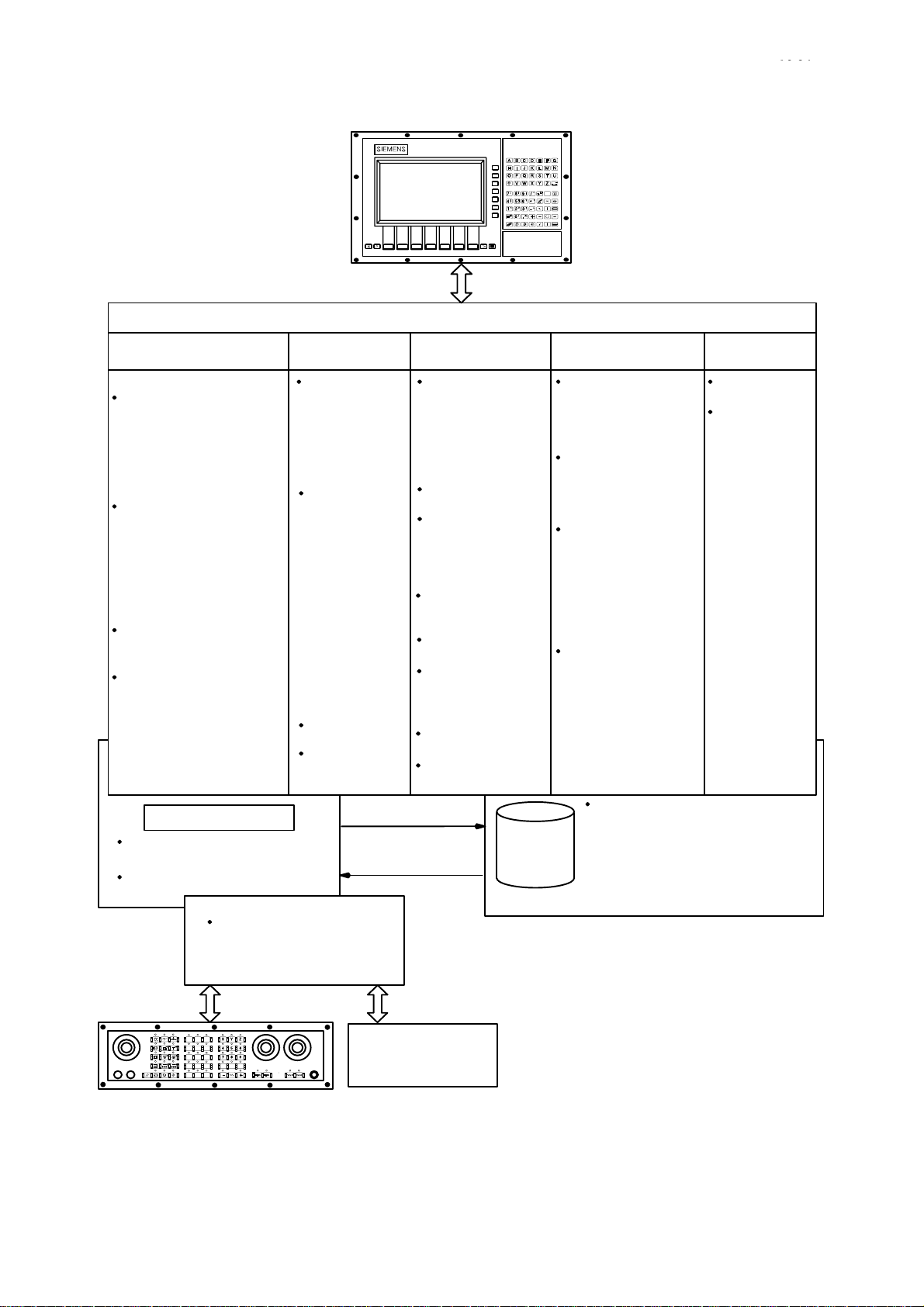
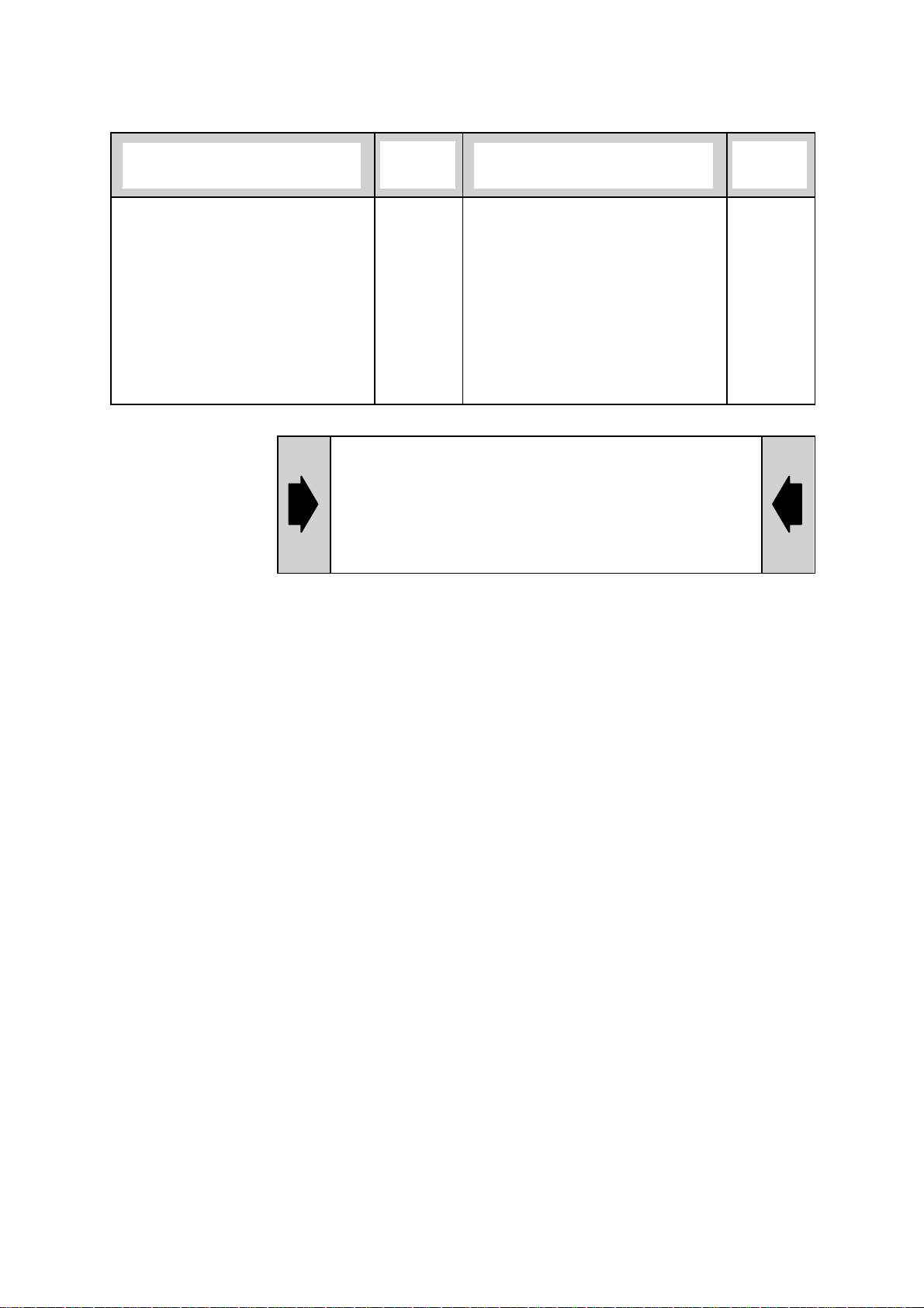
5 operating areas The SINUMERIK 840C operator interface is divided into 5 areas:
MACHINE, PARAMETER, PROGRAMMING, SERVICES and
DIAGNOSIS. The 5 areas will be displayed as softkey functions any time
you press the area switchover key.
Area switchover key
Machine Parameter Programm. Services Diagnosis
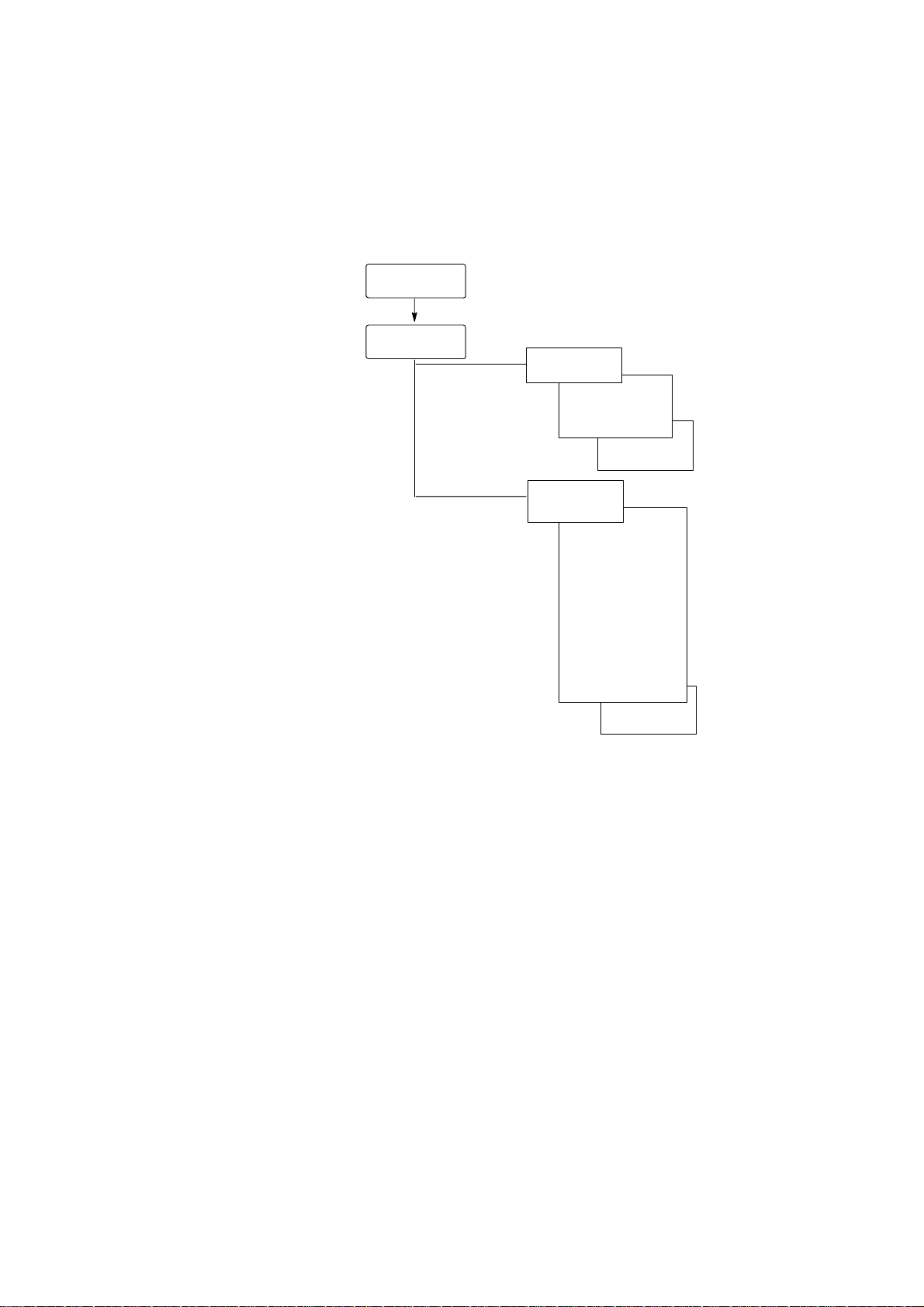
Fig. 1.1 shows you which operator actions are possible in the different
operating areas. With the SINUMERIK 840C, you can edit the part
programs in two different memories:
S in the NCK memory (volatile RAM memory)
S on the hard disk (MMC–CPU).
If you work on the volatile RAM memory, you must store the edited or
newly created programs on the hard disk if they are to be retained after
switching off the control.
If you edit a program on the hard disk, this program must be loaded in
the NCK memory in order to be executed.
For this purpose, the SAVE softkey function is provided in the MACHINE
and PROGRAM areas as well as the SAVE NC function in the
SERVICES area. The PROGRAM area optionally offers a graphic
programming system and a DIN code simulation. You will find a
description of this system in separate publications of the User’s Guide
Graphic Programming System for
S Drilling/Boring and Milling
S Turning
and in User’s Guide, Simulation: Milling and Turning.
Siemens AG 2001 All rights reserved 6FC5198–jAA00
SINUMERIK 840C (BA)
1–3
Page 14
1 Introduction – The SINUMERIK 840C and its Operation
1.2 Structure of the operator interface
Operator panel
Operating areas
10.94
07.97
Machine
Operating mode selection
JOG
– Set-up mode
– Approach reference point
– Incremental traversing
– REPOS
– Handwheel
– Man. traversing
– Overstore
TEACH IN
– Set-up mode
– Incremental traversing
– REPOS
– Handwheel
– Overstore
– Program modification
– Search
MDA
– Overstore
– Program modification
AUTOMATIC
– Overstore
– PRESET
– Program modification
– Search
– Workpiece selection
RAM memory
Part programs and IKA3
data on volatile memory
All other NC data buffered
NCK
Interface control
to the machine
Parameter
Program
parameters
– Tool
offset
– Zero
offset
– Angle of rot.
– R parameters
Setting data
– Working area
limitations
– Spindle data
– Scale
– General data
and bits
– Axial bits
– Position
signals
– Axis/spindle
converter
– Gearbox
interpolation
– Travel against
fixed stop
Computer
link (option)
User
function
(option)
Programming
Editing and
generating
part programs
– Editing in the
NCK area
– Editing on the
hard disk
Generating
workpieces
Delete,
copy and
insert
workpieces
and files
Creating
directories and
files
Generating
job lists
Graphic
programming
system WOP
(option)
DIN simulation
(option)
Graphic tool path
simulation
SAVE
LOAD
Services
Load NC
– Load data from
the hard disk
into the
NCK memory
Save NC
– Save data
from the
NCK memory
to the hard disk
Data in/out
– RS232C (V24) in/out
– Printing data
– Generating and
editing archive
lists
– Device settings
– Clipboard
Data management
– Copy, delete and
insert directories
and files
Storing data on the hard
disk with:
– SAVE NC softkey in the
SERVICES area
– SAVE TO HARD DISK or
SAVE UNDER softkey
Diagnosis
Alarm
displays
Start-up
functions
– NC diagnosis
– PC diagnosis
– PLC diagnosis
MMC–CPU
1–4
PLC
Input/output
machine
control
Siemens AG 2001 All rights reserved 6FC5198–jAA00
SINUMERIK 840C (BA)
Page 15
10.94
1.3 Menu switchover
Softkeys are keys which are variably assigned with functions.
The 5 areas of the SINUMERIK 840C are selected via softkeys. Within
these areas further branching via softkeys is possible.
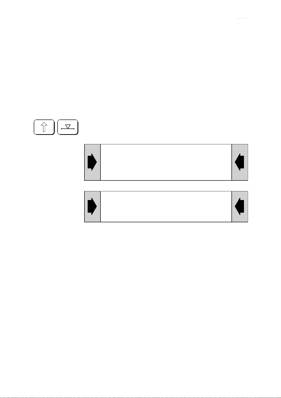
Operating the RECALL key brings you back to the next higher menu
level.
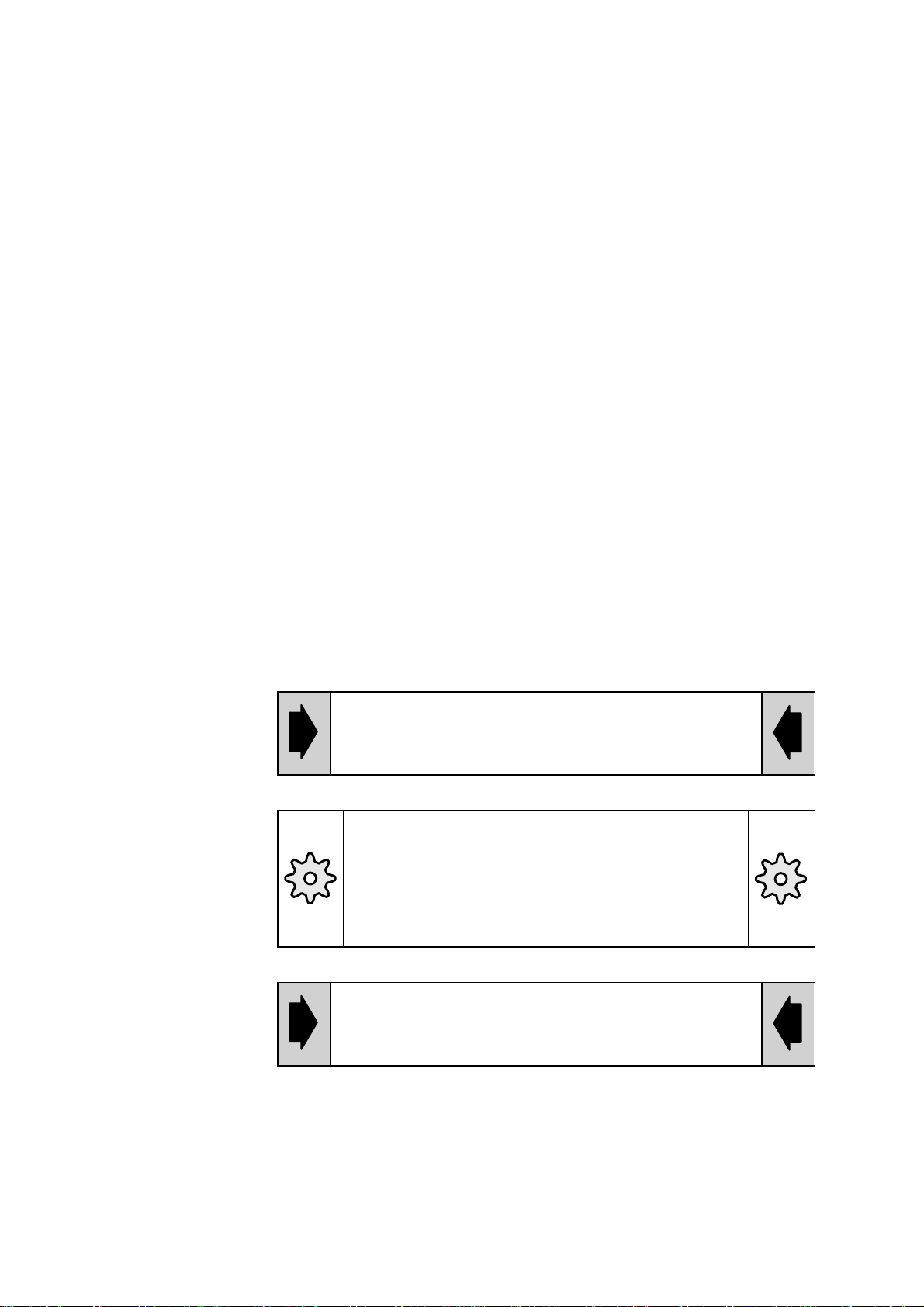
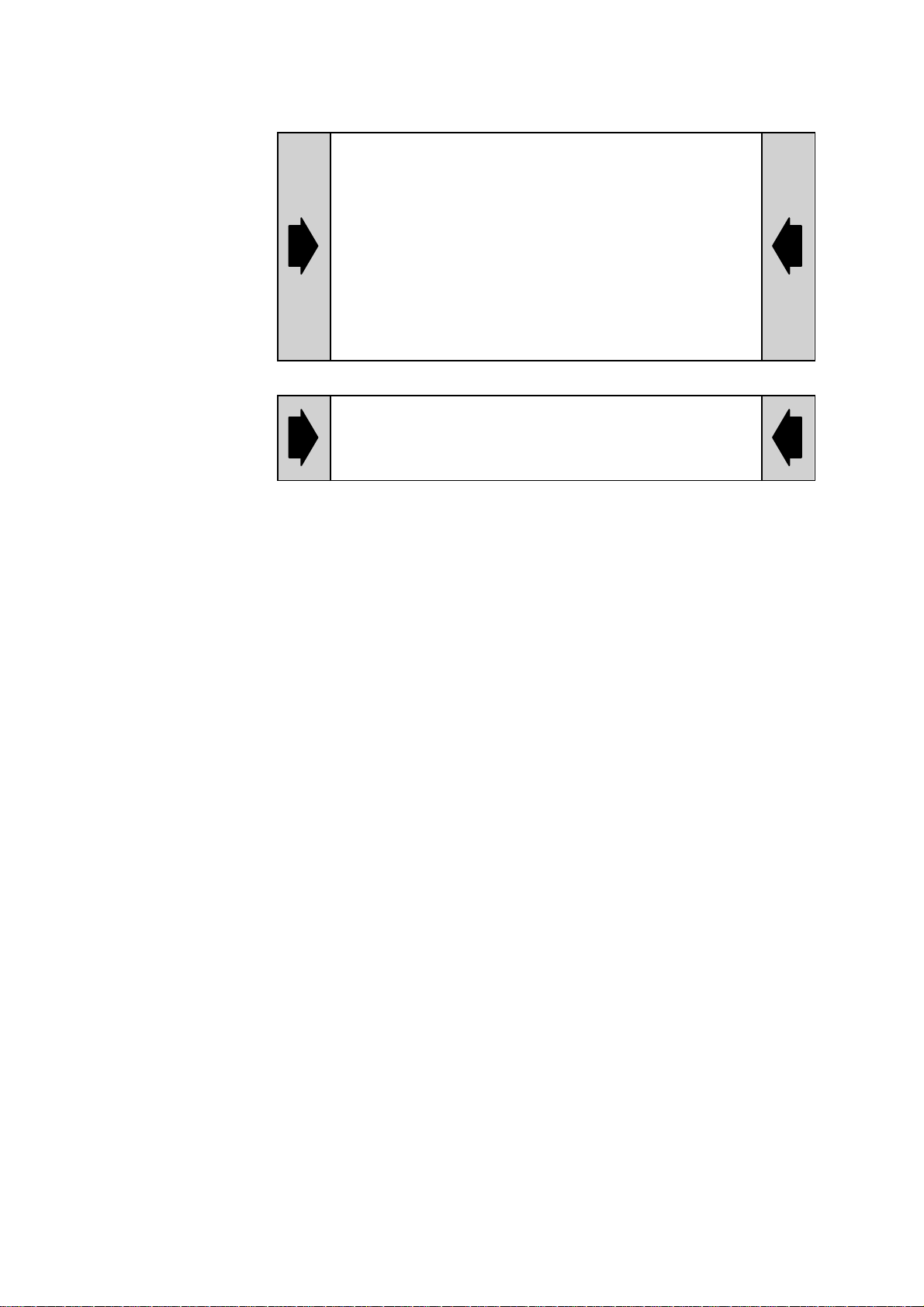
An arrow in the first softkey window indicates that you can return to a
menu:
1 Introduction – The SINUMERIK 840C and its Operation
1.3 Menu switchover
Area menu bar
With the ETC key, you can expand the softkey menu if an extension is
available.
If there is an arrow in the 7th softkey window
(on the right), this key is active.
Siemens AG 2001 All rights reserved 6FC5198–jAA00
SINUMERIK 840C (BA)
1–5
Page 16
1 Introduction – The SINUMERIK 840C and its Operation
1.3 Menu switchover
In each area, the menu last active is stored on area
switchover (exception: MACHINE area).
If you leave an area and do not wish to return to the
menu level currently selected, you switch over to the
main menu of the area with RECALL. This brings you
to the defined initial status of this area. This
procedure simplifies operation when first selecting
the area. By pressing the SHIFT and RECALL keys
you will obtain the basic display immediately from
any branch in the PARAMETER, SERVICES,
DIAGNOSIS and PROGRAMMING areas.
When leaving the area the control “remembers” the
deselected area. This area is selected again by
pressing the area switchover key twice.
10.94
1–6
Siemens AG 2001 All rights reserved 6FC5198–jAA00
SINUMERIK 840C (BA)
Page 17
10.94
04.96
1 Introduction – The SINUMERIK 840C and its Operation
1.4 Directory structure
1.4 Directory structure
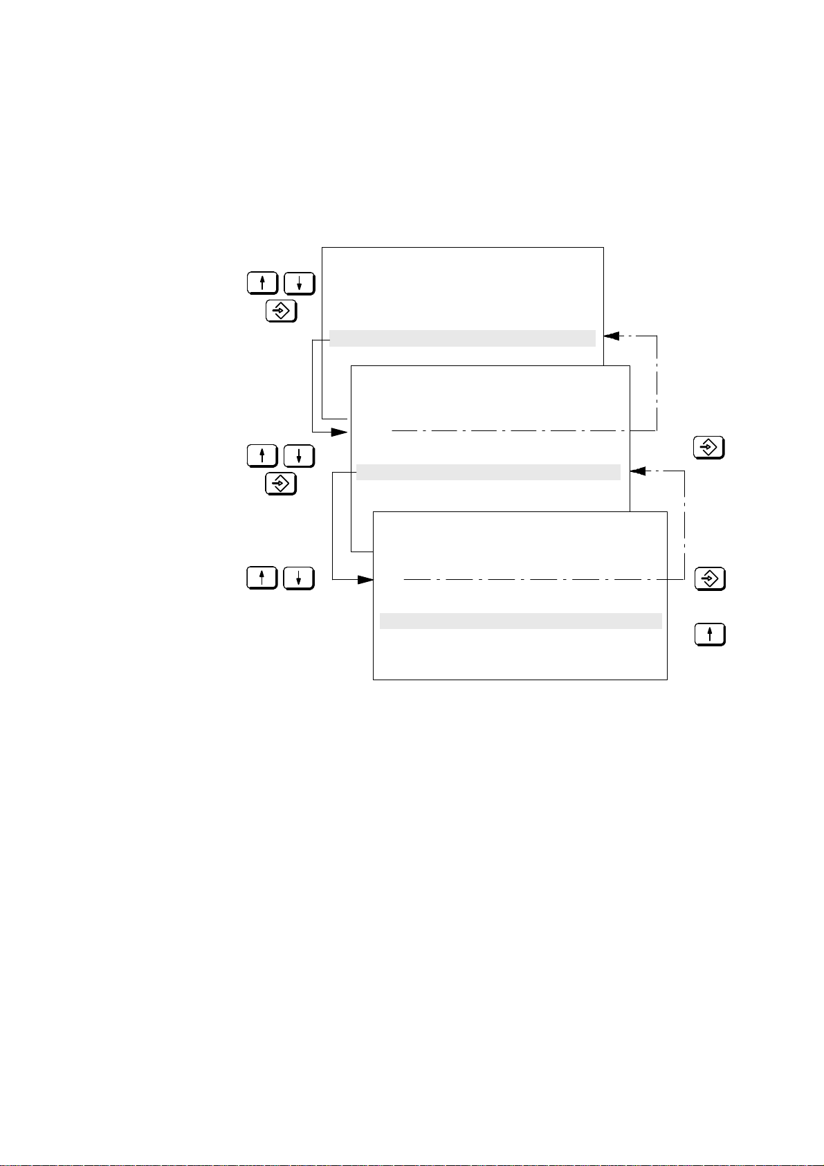
Directories Structures from the PC world have been integrated in the SINUMERIK
840C. The PROGRAMMING, SERVICES and DIAGNOSIS areas as well
as program selection (DATA SELECTOR) contain directories. These
directories are a file management aid for sorting and storing files.
Directories can in turn contain subdirectories. Only one directory level is
displayed on the screen at any one time.
File The softkey bar does not change when you “page” through the
directories. Softkey function and directory are not directly related. A file
is a logical data unit which you can address with a name (e.g. MPF1,
TOA1, ...). Files can be assigned to directories according to specific
criteria, i.e. MPF1 to the workpiece (directory) SHAFT1 or TEA1 to the
directory NC. You can assign directories to other directories, which you
also address with a name (e.g. LOCAL directory).
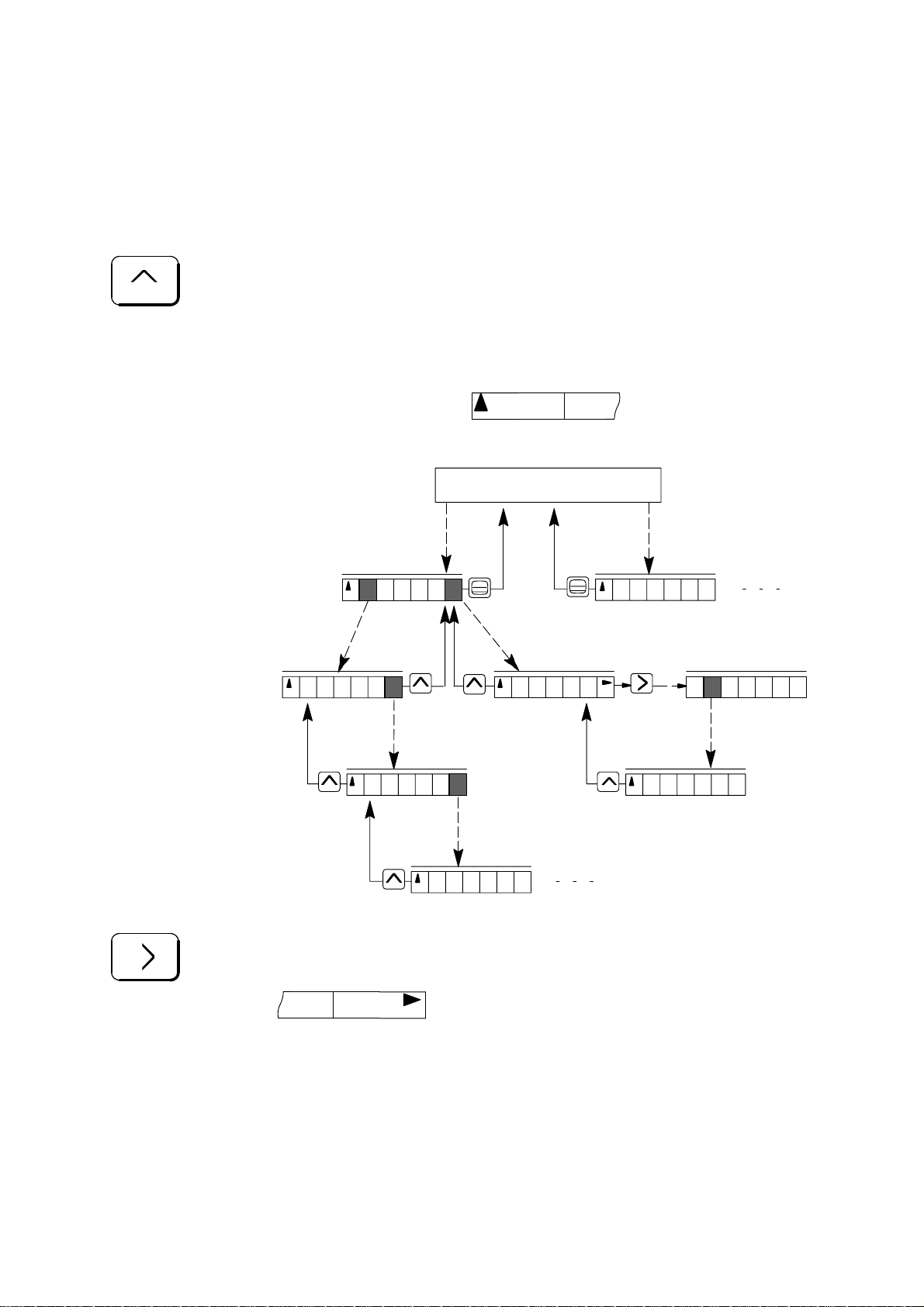
Directory path This results in “directory paths” which you can page through as follows.
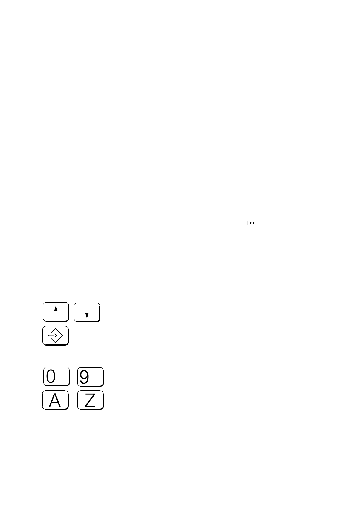
Using the vertical cursor keys, set the cursor on a directory and press
the INPUT key. The next subdirectoy in this directory is opened.
Continue doing this until you have reached the directory of the files. You
recognize files by the entry in the LENGTH column. You reach the next
higher level from a directory level by using the vertical cursor keys to
position the cursor on the line with the double dot
the directory and then acknowledge with INPUT. If you have reached the
highest level, the double dot is replaced by a hyphen.
at the beginning of
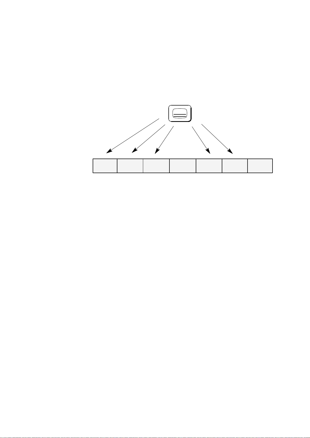
Data selector
Hotkeys
...
...
If you change the area by means of key or softkey functions (e.g.
change from SERVICES to DIAGNOSIS) from any directory, the
directory level last selected is stored. When reselecting the area, this
brings you back to the directory used previously. Switchover between
areas can be performed at any time, e.g. to look at a parameter or
machine data.
A program that interprets your keyboard entries (cursor, input) as a file
or directory selection, displays it on the screen (bar) and passes it on to
other programs (e.g. editor).
With 840C software version 5 and higher the data selector responds to
hotkeys. The first object (directory/file) in the current directory that starts
with the letter or number entered is found and selected.
Siemens AG 2001 All rights reserved 6FC5198–jAA00
SINUMERIK 840C (BA)
1–7
Page 18
1 Introduction – The SINUMERIK 840C and its Operation
1.4 Directory structure
10.94
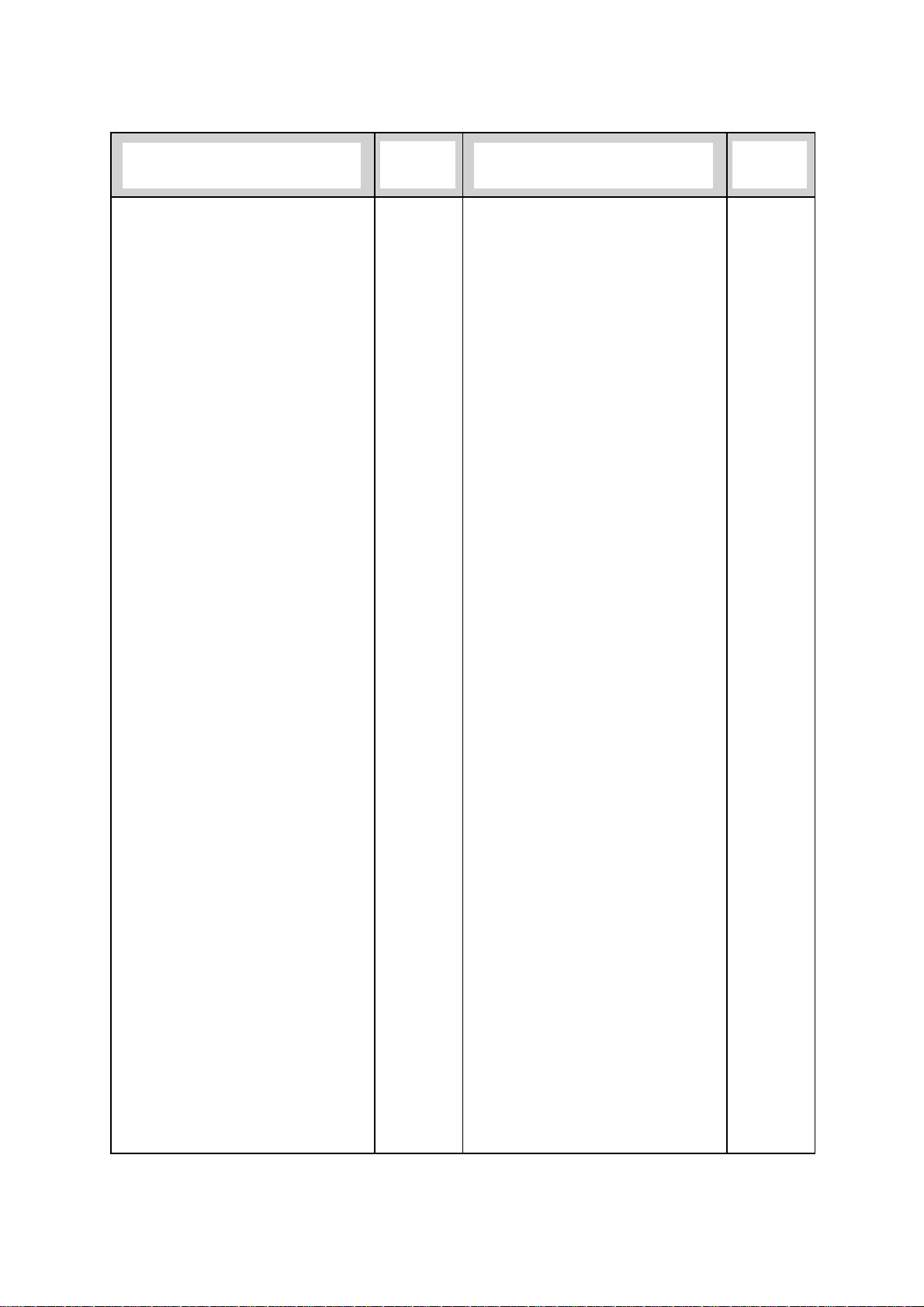
Workpiece With the SINUMERIK 840C you can store part programs and NCK data
(TOA, SEA, RPA, ZOA) in a directory from now on referred to as
workpiece. You can then load this workpiece and its data completely into
the NCK area. Thus you can store all relevant data (part programs, tool
offsets) required for a workpiece under one workpiece name and load it
any time you wish.
Programming/Programs
User
Name Type Length Date
–
GLOBAL glup
LOCAL parts
NCK nck
Programming/Programs
User/LOCAL
Name Type Length Date
..
STANDARD part
PART part
SHAFT1 part
GEAR5 part
Programming/Programs
User/LOCAL
Name Type Length Date
..
MPF1 parp 301 18.04.92
MPF99 parp 256 18.04.92
SPF88 parp 76 18.04.92
TOA1 toa 10250 18.04.92
RPA0 rpa 5637 18.04.92
Fig. 1.1 Representation of the directory path PROGRAMMING/LOCAL/SHAFT1/SPF88
The directory path (e.g. User/LOCAL/SHAFT1) is
displayed each time.
Type In addition to being identified by name, workpieces and files are also
assigned a type identifier. This provides a unique assignment between
the variable name and the created file or directory type. The type
identifiers are as follows:
1–8
Siemens AG 2001 All rights reserved 6FC5198–jAA00
SINUMERIK 840C (BA)
Page 19
10.94
1 Introduction – The SINUMERIK 840C and its Operation
1.4 Directory structure
Designation
Alarm help text
Archive list
Archive lists
Basic settings
Boot strapper
Boot strapper
Boot strapper
Clipboard
Color assignment list
Color table
Comment
Comment text
Configuration
Configuration
Configuration
Configuration texts
Curve pointer
Curve points
Cycle
Cycle machine data (TEA4)
Cycle setting data (SEA4)
Data
Data areas
Data list
Data management
Data references
Device
Device assignment
Drive machine data (TEA3)
Drives
Empirical values
Error texts
Form element
Function
Functions
Function test parameter
Global geometries
Global programs
Graphics
Graphics macro
Graphics mask
Help
Help text
Help text
Help texts
Icons
IKA number
Interfaces
Intermediate save
Job list
Keyboard table
Kinematics
Type Designation Type
alrminf
arc
arcs
bdgl
nckcnf
plccnf
serbo
clip
colli
clut
comm
cmt
bdcnf
simcnf
sycnf
bdcnfl
ika2
ika3
zpf
tea 4
sea 4
mda
dber
lbd
dasy
daref
dev
secnf
tea3
servo
heur
simtxt
gpmk
func
funcs
fkt
glgeo
glup
grfk
gramk
grmsk
wophelp
bdht
texl
htex
ikon
ika1
devs
bak
jobl
kbtab
kine
Language
LB data lists
LB semantics lists
List module
Local programs
Log
Log
Logbook
Logs
Master control
Measured value diagram 1
Measured value diagram 2
Memory dump
Message descriptions
Message descriptions (bin)
Message texts
Message texts (bin)
Motor list
NC
NC machine data (TEA1)
NC macro
NC matching
OEM
Operator action
Options
Part program
PC
PC area
PC system
PC user memory submodule (UMS)
PLC
PLC machine data (TEA2)
Power section list
Programs
R parameter (RPA)
Scheme
Scheme source
Scheme texts
Screen dump
Screen dumps
Screen form
Screen forms
Semantics list
Services
Setting data (SEA)
Siemens
Simulation
Source program
Startup
Startup info texts
Status data (GIA)
System
lang
lbds
lbss
lb
parts
prot
prpr
rlog
prprs
reg
mdi1
mdi2
plcprg
alrmda
alrmd
alrmta
alrmt
motl
nck
tea1
nckmk
nckmd
oem
bedsy
mdd
parp
mmc
mode
sys
mmcasm
plc
tea 2
ltl
progs
rpa
metab
metac
metat
hcpy
hcpys
msk
msks
lbs
serv
sea
siem
simul
sour
ibn
ibninf
gia
ncks
Siemens AG 2001 All rights reserved 6FC5198–jAA00
SINUMERIK 840C (BA)
1–9
Page 20
1 Introduction – The SINUMERIK 840C and its Operation
1.4 Directory structure
Designation Type Designation Type
10.94
System
System file
System file
System files
Templates
Temporary
Text list
Tool catalog
Tool geometry macro
Tool list
Tool offsets (TOA)
plcs
ncsysf
plcsysf
sersy
exam
temp
lbt
toolb
tomk
toli
UMS texts
User
User memory submodule (ASM)
Variable geometry
WOP
WOP control
WOP setup
Workpiece
Work schedule
Zero offsets (ZOA)
toa
250 directories or files can be created for each
directory.
e.g.: Directory LOCAL : 250 workpieces
Directory GLOBAL : 250 workpieces
Directory SHAFT1 : 250 files
etc.
text
user
asm
vgeo
wop
wopst
wopset
part
fainf
zoa
1–10
Siemens AG 2001 All rights reserved 6FC5198–jAA00
SINUMERIK 840C (BA)
Page 21
10.94
1 Introduction – The SINUMERIK 840C and its Operation
1.5 The meaning of the SIEMENS and user directories
1.5 The meaning of the SIEMENS and user directories
The directories are divided into a Siemens directory and a user directory
in the areas where it is sensible to do so:
Softkey
Softkey
SERVICES
DATA
MANAGEMENT
SIEMENS
List module
NC
WOP
Files
User
Operation
Data management
GLOBAL
Start-up
List module
LOCAL
NC
PLC
Master control
Services
Drives
Simulation
WOP
Files
Fig. 1.2 SIEMENS directory and user directory in the SERVICES/DATA
IN–OUT/DEVICES area
Siemens directory The Siemens directory includes all data which are relevant for the
control’s operating system. You cannot edit or read out data in the
Siemens directory; you can merely copy this data into the user directory,
where it can be handled in exactly the same way as user data.
User directory The user directory includes all user data. The fact that system data
copied into the user directory can be edited there makes it possible to
modify the configuration files of the control. The data of the user branch
(if available) are always used before any other for the system
configuration on powering up of the control. These possibilities are only
relevant in the start-up phase and are password-protected against
unauthorized operation.
You will find a possibility to use this structure in the SERVICES/DATA
IN–OUT/DEVICE SETTINGS.
Here you can copy a standard interface configuration from the Siemens
directory into the user directory and modify it in accordance with your
data save device.
Siemens AG 2001 All rights reserved 6FC5198–jAA00
SINUMERIK 840C (BA)
1–11
Page 22
1 Introduction – The SINUMERIK 840C and its Operation
1.6 Screen darkening
1.6 Screen darkening
The SINUMERIK 840C includes a function by which the screen is
darkened after an adjustable period of time.
The default value of this period is 2 hours, i.e. as a rule the screen
darkens 2 hours after a key has last been activated; this value can be
changed in the PC data basic settings in the DIAGNOSIS area. The
display is activated once any key on the alphanumeric keyboard or on
the machine control panel, is pressed. The first keystroke simply
reactivates the screen and does not initiate its normal function. With the
screen darkening function, only the monitor is switched off and all other
functions remain active.
By pressing the SHIFT and ACTUAL POSITION IN LARGE
CHARACTERS keys, you can darken the monitor yourself and reactivate
the display by pressing any key on the alphanumeric keyboard.
Screen darkening can also be implemented by the
machine manufacturer via the PLC program. In this
case, the operator actions mentioned above do not
apply. Refer to the machine manufacturer’s
Operator’s Guide.
10.94
09.95
Caution!
All internal processes which generate screen outputs
do not cancel screen darkening. This also applies to
alarms and operational messages.
1–12
Siemens AG 2001 All rights reserved 6FC5198–jAA00
SINUMERIK 840C (BA)
Page 23
10.94
09.95
1 Introduction – The SINUMERIK 840C and its Operation
1.7 Data backup options
1.7 Data backup options
The memory capacity of the hard disk on the MMC–CPU module
enables you to store large volumes of data in the SINUMERIK 840C. It is
advisable, however, to perform a data dump of all relevant data on an
external data device (programmer, PC, etc.) because the data will be
lost irretrievably if the MMC–CPU (which incorporates the hard disk)
develops a defect.
Archive list As a backup aid, the SINUMERIK 840C allows directories and files to be
archived in archive lists, i.e. you can store a list of all important files and
directories under a name that you specify and output this complete to an
external device (see Services section, “Creating archive lists”).
The SINUMERIK 840C has various hardware interfaces which can be
addressed by the software.
Output via The RS232C (V24)/20mA interface on the MMC–CPU enables you to
RS232C/V24 output your user data from the hard disk in PC format or in punched tape
format (see Services section, “Data input-output”). The interface
automatically changes over between RS232C (V24) and 20 mA mode,
depending on the connected device and corresponding cable.
Constantly update the backup data so that you have
the current data available externally should a fault
occur.
Via the RS232C (V24) interface, you can also print out data directly with
a printer (SERVICES/DATA IN–OUT/PRINT function).
The SINUMERIK FD–E2 diskette unit (option) can be used for backing
up data.
Computer link Optionally you can implement a computer link with the
SINUMERIK 840C (only in the NCK area) by using link modules.
Siemens AG 2001 All rights reserved 6FC5198–jAA00
SINUMERIK 840C (BA)
1–13
Page 24
1 Introduction – The SINUMERIK 840C and its Operation
1.8 Help displays
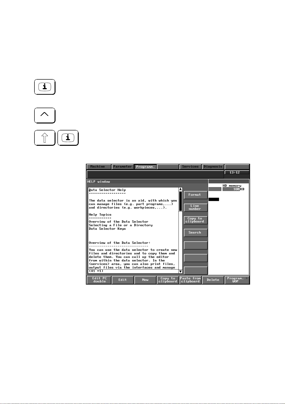
1.8 Help displays
You can call up help displays in the different operating areas of the
SINUMERIK 840C. The following is offered:
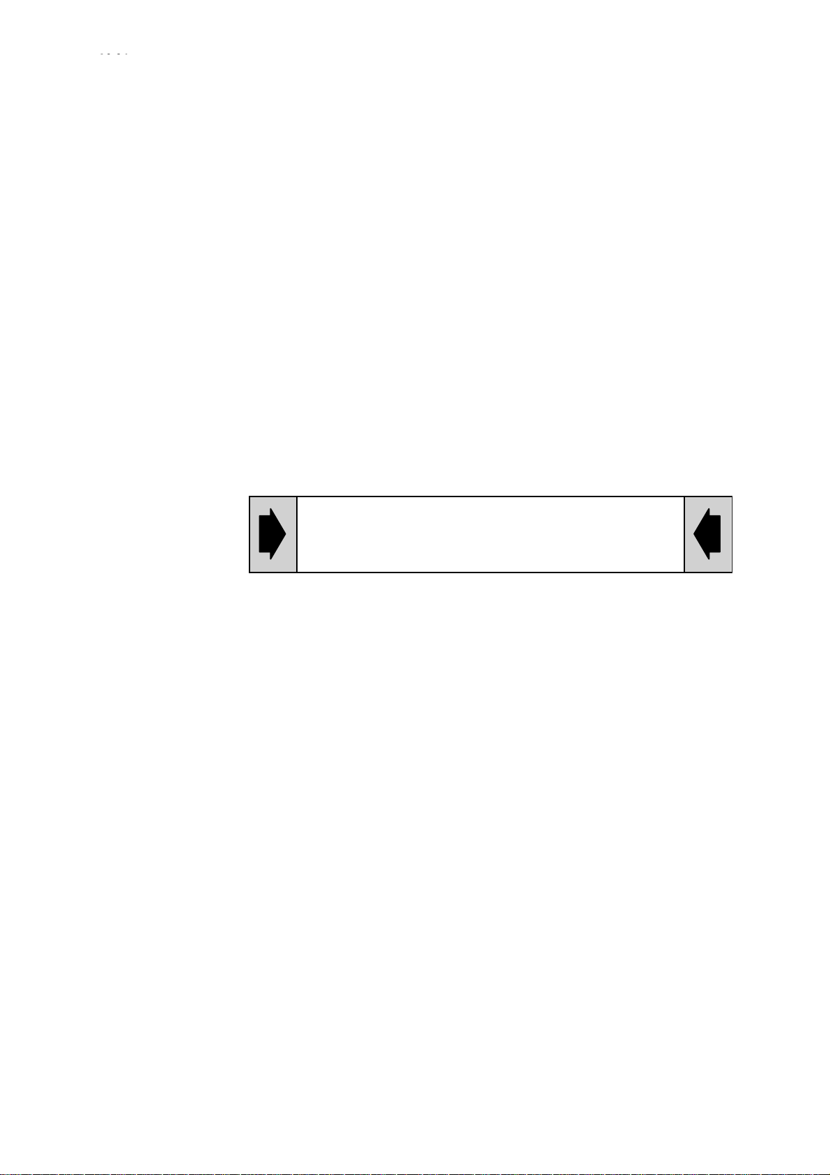
1. With this key you activate a help display for a special operation.
The possibility is indicated by the “i” in the 1st (left) softkey.
Press RECALL to deselect this help screen.
2. By pressing SHIFT + i you select or deselect a help screen
irrespective of an operator action, e.g. help screen for the data
selector:
10.94
1–14
Fig. 1.3 Help display
END OF SECTION
Siemens AG 2001 All rights reserved 6FC5198–jAA00
SINUMERIK 840C (BA)
Page 25

10.94
2 Operator Interface
2.1 Operator panel
Different operator panels can be connected to the SINUMERIK 840C.
The following components can be added: machine control panel, handheld unit and PC standard keyboard (MF–2).
S 19” operating panel with 14” colour monitor
(2x7 softkeys, switchover keys)
S 19” NC full keyboard
(alphabetic group of keys, numeric group of keys, cursor group of
keys)
S 19” slimline operator panel with 9.5” monochrome LC display
including NC full keyboard
(2x7 softkeys, switchover keys, alphabetic group of keys, numeric
group of keys, cursor group of keys)
S 19” slimline operator panel with 10” or 9.5” TFT display including NC
full keyboard
(2x7 softkeys, switchover keys, alphabetic group of keys, numeric
group of keys, cursor group of keys)
S PC standard keyboard (MF–2)
S 19” machine control panel, M version
S 19” machine control panel, T version
S Hand-held unit
Siemens AG 2001 All rights reserved 6FC5198–jAA00
SINUMERIK 840C (BA)
2–1
Page 26
2 Operator Interface
2.2 Operator panel
2.2 Operating elements
2.2.1 Operator panel
10.94
03.95
AB C
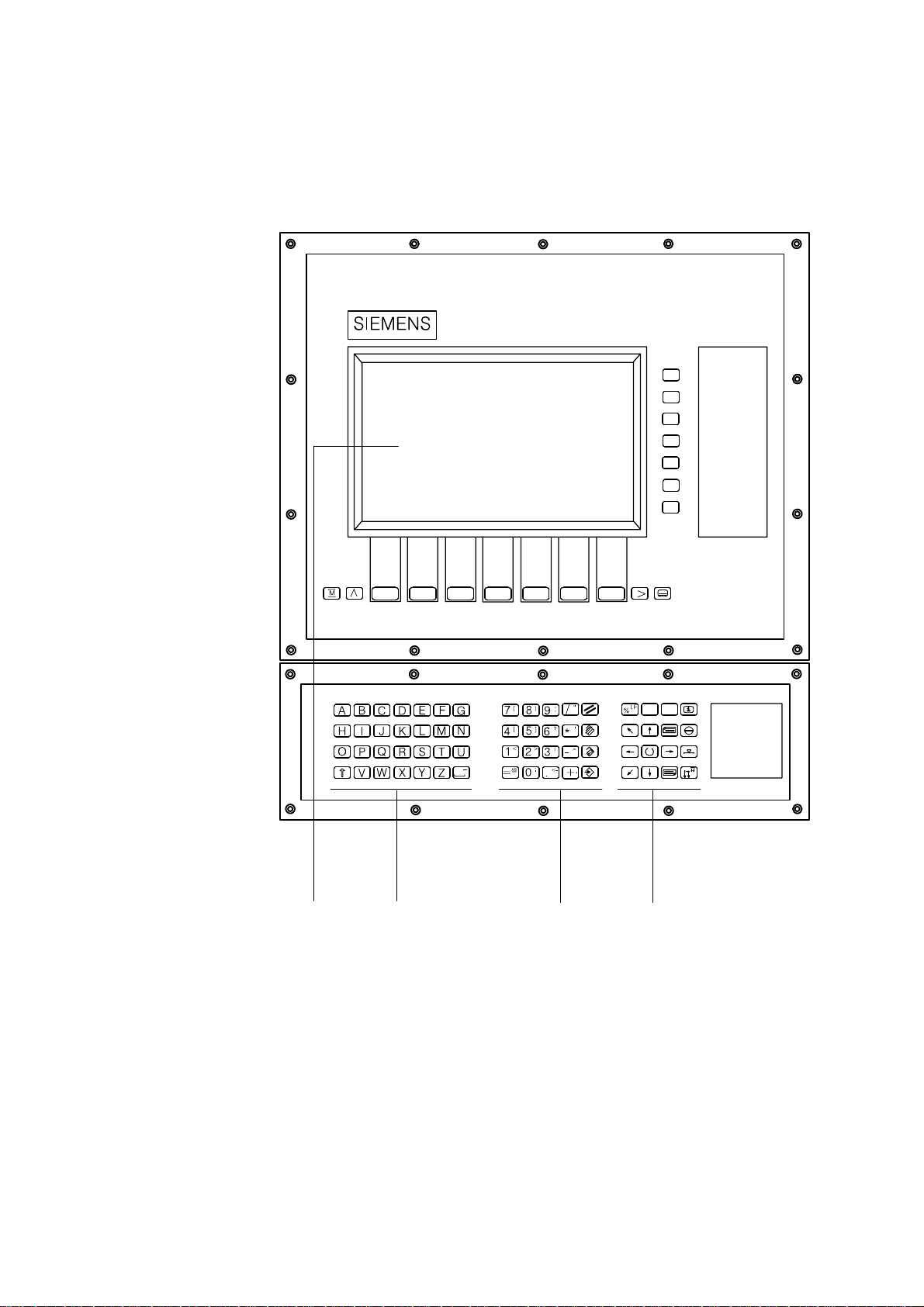
Fig. 2.1 19” operator panel with 14” colour monitor
\
Alt
D
2–2
Siemens AG 2001 All rights reserved 6FC5198–jAA00
SINUMERIK 840C (BA)
Page 27
10.94
03.95
2 Operator Interface
2.2.1 Operator panel
SELECT
MENU
SELECT
\
Alt
D
MACHINE
CLEAR
DELETE
ALTER
SHIFT
INPUT
AB C
Fig. 2.2 19” operator panel with 14” colour monitor in US layout
ALARM
RESET
POSITION
GROUP
CHANNEL
HELP
Siemens AG 2001 All rights reserved 6FC5198–jAA00
SINUMERIK 840C (BA)
2–3
Page 28

2 Operator Interface
2.2.1 Operator panel
ABCD
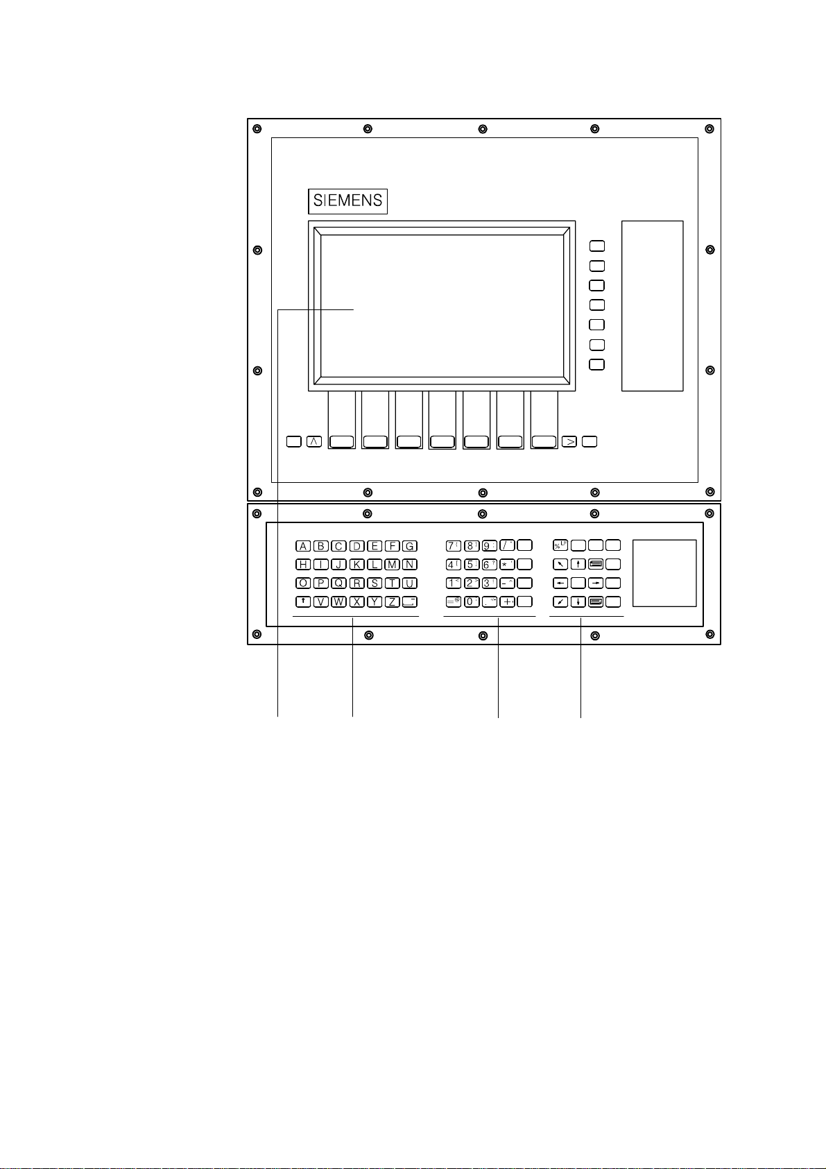
Fig. 2.3 SINUMERIK slimline operator panel
10.94
07.97
\
Alt
SHIFT
GROUP
CHANNEL
CLEAR DELETE ALTER
MACHINE
MACHINE
A CD
MENU
SELECT
B
INPUT
Fig. 2.4 SINUMERIK slimline operator panel in US layout
A: 14”/10”/9.5” colour graphics monitor
14 softkeys
ETC key, Recall key
Machine area key
Area switchover key
B: Alphabetic group of keys
C: Numeric group of keys with editing and input keys
D: Cursor group of keys with control keyboard
POSITION
SELECT
HELP
\
Alt
ALARM
RESET
2–4
Siemens AG 2001 All rights reserved 6FC5198–jAA00
SINUMERIK 840C (BA)
Page 29

10.94
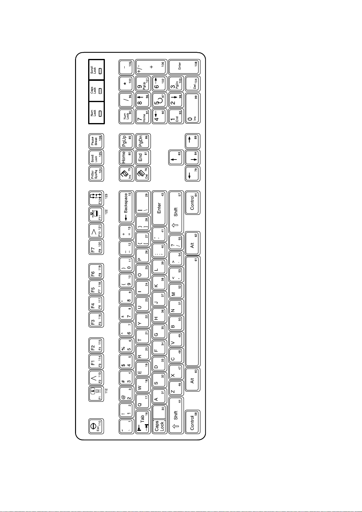
2.2.2 PC standard keyboard (MF–2)
An MF2 full standard keyboard can be connected. The machine control
panel functions, however, cannot be activated via this keyboard.
A set of key caps is supplied with the standard MF2 keyboard. These
key caps correspond to the symbols on the operating panel and can be
mounted on the standard keyboard as shown in the drawing.
The full standard keyboard does not comply with the
conditions (noise immunity) of a SINUMERIK control;
therefore it should be used only for start-up and
during servicing. The MF2 keyboard is connected to
the operator panel interface.
2 Operator Interface
2.2.2 PC standard keyboard (MF–2)
Siemens AG 2001 All rights reserved 6FC5198–jAA00
SINUMERIK 840C (BA)
2–5
Page 30
2 Operator Interface
2.2.2 PC standard keyboard (MF–2)
10.94
Fig. 2.5 Full keyboard
2–6
Siemens AG 2001 All rights reserved 6FC5198–jAA00
SINUMERIK 840C (BA)
Page 31

10.94
2.2.3 Operator panel keyboard / full keyboard
2 Operator Interface
2.2.3 Operating elements of the operator panel keyboard/full keyboard
Softkey: Key which is assigned a variable function via a menu bar on the
screen.
Horizontal softkey bar (full keyboard)
Vertical softkey bar (full keyboard)
The designation F1 to F7 corresponds to the designation on the
additional key caps of the standard keyboard
(see also Figure “Full keyboard”).
MACHINE
or
1)
MENU
SELECT
SHIFT
Machine area
RECALL key: Return to the higher level menu
ETC key: Extension of the softkey bar in the same menu
1)
Area switchover
With this key, you can switch over to the area menu bar from every area.
When an area is deactivated the control “remembers” it. It is activated
again by pressing the area switchover key twice.
Shift: Switching over keys with double allocation; not self-retaining, i.e.
1)
two keys must be activated.
Lower case letter a ... z, activated with SHIFT
Upper case letter A ... Z
...
Underscore
Blank, space
1) US layout
Siemens AG 2001 All rights reserved 6FC5198–jAA00
SINUMERIK 840C (BA)
2–7
Page 32

2 Operator Interface
2.2.3 Operator panel keyboard / full keyboard
Special character: less than
Digit 1
Special character: greater than
Digit 2
Exclamation mark
Digit 3
Square bracket
Digit 4
Square bracket
Digit 5
10.94
Question mark
Digit 6
Round bracket
Digit 7
Round bracket
Digit 8
Colon
Digit 9
Semicolon
Digit 0
2–8
Inverted commas
Oblique stroke, division
Apostrophe
Multiplication
Siemens AG 2001 All rights reserved 6FC5198–jAA00
SINUMERIK 840C (BA)
Page 33

10.94
03.95
2 Operator Interface
2.2.3 Operator panel keyboard / full keyboard
Special character
Hyphen, subtraction
Special character
Equal sign
Comma
Plus, addition
Change of sign
Fullstop (point/period)
or
1)
CLEAR
or
DELETE
ALTER
INPUT
or
Delete character/entry
1)
Delete word
Edit word
1)
1)
Confirm input (store an edited value in the memory)
Line Feed; identifier for end of block
Percent sign; identifier for beginning of main program
Backslash
\
Alt
1) US layout
Siemens AG 2001 All rights reserved 6FC5198–jAA00
SINUMERIK 840C (BA)
Alt
2–9
Page 34

2 Operator Interface
2.2.3 Operator panel keyboard / full keyboard
Help
1)
HELP
This key can be used to call up explanations and information on the
current operating state.
Pressing it a second time brings you back to the previous display (but
or
+
not in the graphic programming system). The “i” in the softkey bar
indicates the possibility of calling up information by pressing the “Help”
key.
Actual position in large characters
1)
POSITION
When you operate this key, the CRT display of “Actual position” is shown
in double-height characters.
Operating the key again brings you back to the previous full CRT display
or
(with standard size characters).
+
10.94
or
You “page” up by one display.
You change the current screen display by operating one of these keys if
further screen displays of the same layout (lists) are available.
or
You “page” down by one display. In a part program you can page down
the display (towards the end of the program), or up (towards the
beginning of the program).
With these keys, you move the cursor on the screen to the left or to the
right, upwards (back) or downwards (forward).
With the cursor keys, you can move the cursor in the input fields (toggle
fields, etc.) or in the various editors (ASCII editor; DIN editor). Further
information is given in the respective Sections of this Operator’s Guide.
Change to another input window
or
1) US layout
2–10
or
With this key you activate the cursor in the input line (NCK only), move it
by means of the cursor keys, in order to correct or insert. When
operating the key again, you deactivate the cursor.
Siemens AG 2001 All rights reserved 6FC5198–jAA00
SINUMERIK 840C (BA)
Activate/deactivate cursor in the input line
Page 35

10.94
SELECT
Acknowledge alarm
ALARM
RESET
2 Operator Interface
2.2.3 Operator panel keyboard / full keyboard
1)
Selection key/Search key
(toggle fields select/mark text in editor/search text)
SHIFT + selection key
(reset a toggle field)
SHIFT + ALTER
Copy the contents of the screen into a file (hardcopy!)
You will find the TIF file “HCFn” (n = 0, 1, ...) in directory “Services/
Screen shots”
Memory requirement on the hard disk:
mono approx. 300 KB / screen
color (compressed) approx. 20 kB / screen
1)
By pressing this key you acknowledge the information from the NC
monitoring system displayed in the alarm line such as:
S Alarm text and
S Alarm number for CANCEL alarms
– The machine manufacturer can configure whether this key is to act
on all channel-specific CANCEL alarms or only on the channelspecific CANCEL alarms of the current channel.
1)
GROUP
CHANNEL
Change of mode groups
Channel switchover
Change of mode
groups The NC channels are grouped together in mode groups. With the
SINUMERIK 840C up to 6 mode groups can be selected.
Please note:
The channels are assigned to mode groups by
the machine manufacturer.
Channel switchover
S Pressing this key once switches to the next higher channel number,
referred to the number displayed in the channel status field.
S Pressing the key again switches on to the next
channel or back.
S The channel can be selected directly by entering the channel number
and then operating the key.
S The NC area of the SINUMERIK 840C is divided into a maximum of
six channels.
1) US layout
Siemens AG 2001 All rights reserved 6FC5198–jAA00
SINUMERIK 840C (BA)
2–11
Page 36

2 Operator Interface
2.2.4 The operating elements of the machine control panel
2.2.4 The operating elements of the machine control panel
Machine control panel for a milling machine
10.94
Machine control panel for a milling machine in US layout
REPOS
[VAR]
CYCLE
STOP
REF
POINT
CYCLE
START
4th
5th
AXIS
AXIS
7th
8th
AXIS
AXIS
RAPID
RESET
JOG
TEACH IN
MDI
AUTO
SINGLE
BLOCK
Machine control panel for a turning machine
FEED
STOP
60
10
100
0
120
%
60
10
100
0
FEED
START
120
%
90
80
80
SPINDLE
START
100
110
120
%
90
100
110
120
%
70
60
50
6th
AXIS
9th
AXIS
70
60
SPINDLE
STOP
50
Machine control panel for a turning machine in US layout
REPOS
[VAR]
CYCLE
STOP
REF
POINT
CYCLE
START
RAPID
JOG
TEACH IN
MDI
AUTO
SINGLE
RESET
BLOCK
Fig. 2.6 Machine control panels
70
60
70
60
SPINDLE
STOP
FEED
STOP
60
10
100
0
120
%
60
10
100
0
FEED
START
120
%
90
80
100
110
120
50
%
90
80
100
110
120
50
%
SPINDLE
START
2–12
Siemens AG 2001 All rights reserved 6FC5198–jAA00
SINUMERIK 840C (BA)
Page 37

10.94
2 Operator Interface
2.2.4 The operating elements of the machine control panel
Machine tool operations such as traversing of the axes or program start
can only be triggered via a machine control panel.
The machine tool can be equipped with a standard Siemens machine
control panel or with a special machine control panel from the machine
tool manufacturer.
A maximum of two mode groups is possible.
The standard Siemens machine control panel is described. Should
another machine control panel be used, please refer to the Operator’s
Guide of the machine tool manufacturer.
The standard Siemens machine control panel has the following
operating elements:
S Emergency stop button
S Operating modes with function keys
S Spindle control
S Feed control
S Direction keys with rapid override
S Keyswitch
S Reset key
S Program control
Emergency stop You operate the red button in emergency situations:
button
S When there is a danger to life.
S When there is a danger that the machine or the workpiece could be
damaged.
Operation of the “Emergency stop” button generally brings all drives to a
stop with maximum braking torque.
For further or other reactions to “Emergency
stop”, refer to the machine tool manufacturer’s
documentation.
Siemens AG 2001 All rights reserved 6FC5198–jAA00
SINUMERIK 840C (BA)
2–13
Page 38

2 Operator Interface
2.2.4 The operating elements of the machine control panel
Operating modes
10.94
Key symbol
JOG
The axes are traversed continuously in
1)
JOG mode using the direction keys or
incrementally using the direction keys or
Definition
the handwheel.
1)
Interactive creation of programs
TEACH IN
1)
The machine is controlled by executing a
MDI
block or a series of blocks. The operator
panel is used to input blocks.
1)
The machine is controlled by automatic
AUTO
execution of programs.
If a mode key is pressed, the corresponding mode is selected and all
other modes and functions are cancelled.
The active mode is indicated and confirmed by the associated LED
lighting up.
“REPOS” and “Approach reference point” functions
Designation of
operating mode
JOG
Set-up
(Jogging)
TEACH IN
MDA
Manual Data Automatic
AUTOMATIC
Key symbol
REPOS
REF
POINT
Definition
Designation of
function
1)
Repositioning, approach contour again in
JOG mode
1)
Approach reference point in JOG mode
REPOS
Reposition
REFPOINT
Approach reference point
The “REPOS” and “Approach reference point” functions are only active
in JOG mode and can be selected only in JOG mode.
The active function is indicated by the associated LED lighting up.
The function can be cancelled by pressing the function key again. The
function is cancelled automatically if there is a change of operating
mode.
1) US layout
2–14
Siemens AG 2001 All rights reserved 6FC5198–jAA00
SINUMERIK 840C (BA)
Page 39

10.94
09.95
INC function
2 Operator Interface
2.2.4 The operating elements of the machine control panel
Key symbol Definition
1)
Increment mode with variable step size
[VAR]
(setting data).
Increment mode with fixed step size of
1 increment
Increment mode with fixed step size of
10 increments.
Increment mode with fixed step size of
100 increments.
Increment mode with fixed step size of
1000 increments.
Increment mode with fixed step size of
10 000 increments.
The increment size depends on the display resolution that has been set.
Designation of
function
INC VAR
Incremental Feed variable
INC
Incremental Feed
Spindle override switch
9080
70
60
50
100
110
120
%
The INC functions can be activated in conjunction with the following
modes:
S JOG mode
S TEACH IN mode.
S The rotary switch with 16 notched positions (of which 15 are used)
enables you to reduce or increase the programmed spindle speed S
(corresponds to 100%).
S A machine data determines whether the switch function is active, i.e.
it is determined by the machine manufacturer.
S The set spindle speed value S is displayed as an absolute value in %
on the CRT display.
Control: 50% to 120% of the programmed spindle speed
Step size: 5% from position to position
1) US layout
Siemens AG 2001 All rights reserved 6FC5198–jAA00
SINUMERIK 840C (BA)
2–15
Page 40

2 Operator Interface
2.2.4 The operating elements of the machine control panel
The given step size and the control range are
valid for standard machine data (MD). These
can be altered by the machine tool manufacturer
to suit a specific application.
Spindle stop When you press the SPINDLE STOP key:
SPINDLE
STOP
1)
S The spindle speed is reduced down to zero
S The associated LED lights up as soon as SPINDLE STOP is
accepted by the control.
Example for use of SPINDLE STOP
S To effect tool change
S To enter S, T, H, M functions while setting up (overstoring)
Spindle start When you press the “Spindle start” key:
1)
SPINDLE
START
S The spindle is enabled. If the spindle has been stopped with
SPINDLE STOP in a program, it can be started again with SPINDLE
START.
10.94
07.97
S The associated LED lights up as soon as SPINDLE START is ac-
cepted by the control.
The following values are specified by machine
data or setting data:
S The maximum spindle speed
S The values for spindle override positions
(refer to the machine tool manufacturer’s
documentation)
Feedrate control Feedrate/rapid override
The rotary switch with 23 notched positions allows you to reduce or
increase the programmed feedrate value F (corresponds to 100%).
90
100
The set feedrate value F is indicated on the CRT display in %.
110
Control range: 0% to 120% of the programmed feedrate.
The 100% value is not exceeded in rapid traverse.
10
6
60
70
40
20
2
0
80
120
%
Step size: 0%, 1%, 2%, 4%, 6%, 8%, 10%, 20%, 30%, 40%,
50%, 60%, 70%, 75%, 80%, 85%, 90%, 95%, 100%,
105%, 110%, 115%, 120%
1) US layout
2–16
Siemens AG 2001 All rights reserved 6FC5198–jAA00
SINUMERIK 840C (BA)
Page 41

10.94
2.2.4 The operating elements of the machine control panel
The given increment sizes and the control range
are valid for
standard machine data (MD)
These can be altered by the machine tool
manufacturer to suit a specific application.
Feed stop When you operate the FEED STOP key:
1)
FEED
STOP
S The program being executed is stopped
S The feed drives are brought to a controlled stop
S The associated LED lights up as soon as FEED STOP is accepted by
the control.
Examples for use of FEED STOP:
S During application in MDA mode, a block with a fault is discovered
S To effect tool change.
Feed start When you operate the FEED START key:
1)
FEED
START
S The part program continues in the current block
S The feedrate is increased to the value specified by the program
2 Operator Interface
S The associated LED lights up as soon as FEED START is accepted
by the control.
Direction keys, turning machine
You traverse the axis marked X.
You traverse the axis marked Z.
The following is configured by the machine
manufacturer:
S The speed and rapid traverse rates
S The values for feedrate and override positions
S Whether the feedrate override switch is also
active for rapid traverse
S The axis names
(see machine manufacturer’s specifications)
You traverse the axis marked C.
1) US layout
Siemens AG 2001 All rights reserved 6FC5198–jAA00
SINUMERIK 840C (BA)
2–17
Page 42

2 Operator Interface
2.2.4 The operating elements of the machine control panel
Rapid traverse override
1)
RAPID
When you operate this key at the same time as any of the keys above,
the axis is traversed in rapid traverse mode.
Direction keys, milling machine
You select the axis marked X, Y, Z etc.
You traverse the selected axis in positive or in negative direction.
You traverse other assigned axes in the same way.
10.94
09.95
If an INC function has been set and the direction key is pressed
(whether for a long or a short time), the axis traverses by only one step
(1/10/100/1000/10000 increments depending on the setting).
If an INC function is not selected, the default setting “continuous” is active. The axis traverses as long as the
direction key is pressed.
Please take into consideration that when the safety interlocks are
enabled only the simple traverse movement via the JOG keys or via the
handwheel is permitted.
Rapid traverse When you operate this key at the same time as any of the keys above,
override the axis is traversed in rapid traverse mode.
1)
RAPID
1) US layout
2–18
Siemens AG 2001 All rights reserved 6FC5198–jAA00
SINUMERIK 840C (BA)
Page 43

10.94
09.95
2.2.4 The operating elements of the machine control panel
2 Operator Interface
Keyswitch The SINUMERIK 840C keyswitch has 4 positions which are assigned
with functions via the control’s operating system. Three keys of different
colours belong to the keyswitch and these can be turned and removed
from the following positions:
Position of switch Withdraw position
Position 0
– Data on the hard disk are only displayed
Position 1
0 + 1 key 1
black
Position 2
0 + 1 + 2 key 2
green
Position 3 0+1+2+3 key 3
red
The key positions can be assigned with
additional functions by the machine
manufacturer. Please read the machine
manufacturer’s Operator ’s Guide.
Function
Generate, edit and delete workpiece data
Generate, edit and delete interface data,
archive lists and setting data
Siemens MMC standard data is loaded into
the system when powering up. All data in the
directory is password-protected. Note: Use
only for start-up and servicing!
Note If the PLC is in the STOP state the input display on the machine control
panel is not scanned. In this case the control can be powered up via
keyswitch position 3.
Reset key
1)
When you operate the “Reset” key:
RESET
S Execution of the current part program is interrupted if the key triggers
a mode group Reset (= Reset of all the channels of the mode group).
S Messages are cleared from the monitoring system unless they are
POWER ON or acknowledgment alarms.
S The control is switched to the “Reset” state, i.e.
– The NC control remains synchronized with the machine.
– All buffer and user memories are cleared (but the contents of the
part program memory are retained).
– The control is in the Reset state and ready for a new program run.
1) US layout
Siemens AG 2001 All rights reserved 6FC5198–jAA00
SINUMERIK 840C (BA)
2–19
Page 44

2 Operator Interface
2.2.4 The operating elements of the machine control panel
10.94
The machine manufacturer can configure the
RESET key such that it acts on channel/mode
group or on the whole NC.
Single block This function allows you to execute a part program on a block-by-block
1)
SINGLE
BLOCK
basis.
The SINGLE BLOCK function can be activated in the AUTOMATIC,
TEACH IN and MDA modes.
When SINGLE BLOCK operation is active:
S The SBL (Single Block) message is shown on the CRT display
S The current block of the part program is executed only when you
press the “NC start” key
S When the current block has been executed, processing is stopped
S The following block can be executed by pressing the “NC start” key
again.
The function does not work with calculation blocks. Calculation blocks
are part program blocks which execute programmed calculations (R
parameters calculation operations), but do not output anything to the
machine or to the PLC.
If SINGLE BLOCK is activated, the corresponding LED lights up on the
machine control panel.
The function can be deselected by pressing the key again.
NC Stop If you press the NC STOP key, processing of the current part program is
1)
CYCLE
STOP
interrupted. All axis movements are brought to a controlled stop. The
reactions of the H and M functions in the case of NC STOP are
configured by the machine manufacturer. For more information refer to
the machine manufacturer’s documentation. The associated LED lights
up.
Processing can then be continued by pressing NC START.
NC Start If you press the NC START key, the part program called is started at the
1)
CYCLE
START
current block; the associated LED lights up. Processing of a part
program interrupted with NC STOP is continued at the point of
interruption on pressing NC START.
The axis positions programmed in the current block
are approached with linear interpolation after the “NC
START” key has been activated.
Caution: Risk of collision!
1) US layout
2–20
Siemens AG 2001 All rights reserved 6FC5198–jAA00
SINUMERIK 840C (BA)
Page 45

10.94
2.2.5 Operating elements on the hand-held unit
2.2.5 Operating elements on the hand-held unit
The display and key functions can be configured
by the machine manufacturer. For further details
refer to the machine manufacturer’s
documentation. The standard keyboard is
described below.
SIEMENS
2 Operator Interface
50
60
40
30
20
10
100
0
110
Fig. 2.7 Operating elements of the hand-held unit
%
70
80
90
Siemens AG 2001 All rights reserved 6FC5198–jAA00
SINUMERIK 840C (BA)
2–21
Page 46

2 Operator Interface
2.2.5 Operating elements on the hand-held unit
10.94
Operating and S 20 user-assignable keys; symbol labels can be replaced (hand-held
display elements unit must be opened to access the labels).
S 1 rapid traverse/feedrate override switch
S 2 enabling devices
S 1 keyswitch
S 1 emergency STOP pushbutton
S 1 electronic handwheel
S 16 user-controllable LEDs
S 1 two-line numerical display (2 x 16 characters)
2.2.6 Operating elements on the A–MPC hand-held unit
Operating modes
Key symbol Definition
Jogging the machine by a continuous
movement of the axes using the direction
keys or by incremental movement of the
axes using the direction keys or the handheld unit
Creating programs interactively with the
machine
Pressing a particular operating mode key selects the corresponding
operating mode, all other operating modes and functions are deselected.
The LED for the selected operating mode lights up to indicate and
confirm that the operating mode is active.
Feed stop When you press the FEED STOP key:
S Processing of the current program is stopped
S The feed drives are stopped under control
S The corresponding LED lights up as soon as FEED STOP has been
accepted by the control.
Operating mode
JOG
set-up
(Jogging)
TEACH IN
2–22
Example applications of FEED STOP:
S An error is detected while running a program in MDA mode
S To carry out a tool change.
Siemens AG 2001 All rights reserved 6FC5198–jAA00
SINUMERIK 840C (BA)
Page 47

10.94
01.99
Feed start Press the key FEED START:
S The part program is continued in the current block
S The feedrate is increased to the value defined in the program
S The corresponding LED lights up as soon as FEED START has been
accepted by the control.
The machine manufacturer configures the
following:
S The feed and rapid traverse velocities
S The values for the feedrate override settings
S Whether the feedrate override switch is also
active for rapid traverse
S The axis names
(see information supplied by machine-tool
manufacturer)
2 Operator Interface
2.2.6 Operating elements on the A–MPC hand-held unit
Spindle stop Press the SPINDLE STOP key:
S The spindle speed is reduced to zero speed
S The corresponding LED lights up as soon as SPINDLE STOP is
accepted by the control.
Example application of SPINDLE STOP
S To carry out a tool change
S To enter S, T, H and M functions during set-up (overstore)
Spindle start Press the SPINDLE START key:
S The spindle is enabled. If the spindle has been stopped with
SPINDLE STOP in a program, it can be started again with SPINDLE
START.
S The corresponding LED lights up when “Spindle start” is accepted by
the control.
The following is defined in the machine data or
setting data:
S The maximum spindle speed
S The values for the spindle speed override
settings
(see information supplied by the machine-tool
manufacturer)
NC Stop If you press the NC STOP key processing of the current part program is
interrupted. All axis movements are brought to a controlled stop.
H and M function responses on NC STOP are configured by the machine-tool manufacturer. Please refer to the documentation supplied by
Siemens AG 2001 All rights reserved 6FC5198–jAA00
SINUMERIK 840C (BA)
2–23
Page 48

2 Operator Interface
2.2.6 Operating elements on the A–MPC hand-held unit
the machine-tool manufacturer. The corresponding LED lights up. You
can then continue machining with NC START.
NC Start Press the key NC START to start the part program you have called at
the current block; the corresponding LED lights up. After interrupting
processing of a part program with NC STOP, processing is continued
with NC START at the point of interruption.
The axis positions programmed in the current block
are approached with linear interpolation when NC
START is activated.
Caution: risk of collision!
You select the axis marked X, Y, Z etc.
10.94
You traverse the selected axis in positive or in negative direction.
You traverse other assigned axes in the same way.
If an INC function has been set and the direction key is pressed
(whether for a long or a short time), the axis traverses by only one step
(1/10/100/1000/10000 increments depending on the setting).
If an INC function is not selected, the default setting “continuous” is
active. The axis traverses as long as the direction key is pressed.
Please take into consideration that when the safety interlocks are
enabled only the simple traverse movement via the JOG keys or via the
handwheel is permitted.
Rapid traverse When you operate this key at the same time as any of the keys above,
overlay the axis is traversed in rapid traverse mode.
Handwheel active This handwheel function must be configured by the machine-tool
manufacturer.
2–24
Siemens AG 2001 All rights reserved 6FC5198–jAA00
SINUMERIK 840C (BA)
Page 49

10.94
09.95
2 Operator Interface
2.2.6 Operating elements on the A–MPC hand-held unit
Keyswitch The SINUMERIK 840C keyswitch on the hand-held unit has 4 positions
which can be assigned functions by the machine manufacturer. Three
keys of different colours belong to the keyswitch which can be turned
and removed in the stated positions (see “Position of switch” and “Withdraw position” for the machine control panel!).
The key positions can be assigned with
functions by the machine manufacturer. Please
read the machine manufacturer’s Operator’s
Guide.
Note If the PLC is in the STOP state, the input display on the machine control
panel is not scanned.
Feed control Feedrate override
50
60
40
30
70
80
20
90
10
100
0
110
The increment values displayed and the
control range only apply to standard machine data. Please refer to the documentation supplied by the machine-tool manufacturer.
Electronic
handwheel
Siemens AG 2001 All rights reserved 6FC5198–jAA00
SINUMERIK 840C (BA)
2–25
Page 50

2 Operator Interface
2.2.7 Screen layout
2.2.7 Screen layout
23 4 56
1
10.94
Meaning of
screen boxes
78
Fig. 2.8 Screen layout
9
10 11
1 – Mode, operating function, channel state (area-specific)
2 – Alarms, messages, comments
3 – Display of the selected area
4 – Channel status, program modification display
(area-specific)
5 – Clock, clear condition for present alarm, channel-independent
status display by means of icons
6 – Mode group and channel number (area-specific)
7 – Operating window, NC displays, texts, input keys
8 – Interactive text (area-specific)
9 – Softkey bar with 7 softkey functions
10 – Input (area-specific)
2–26
11 – Softkey bar with 7 softkey functions (area-specific)
END OF SECTION
Siemens AG 2001 All rights reserved 6FC5198–jAA00
SINUMERIK 840C (BA)
Page 51

10.94
3 Machine
Machine Parameter Programm Services Diagnosis
3.1 Operating modes
3.1.4 JOG
(Set-up)
3.1.4.1
Traversing in JOG
mode
3.1.4.2
Approach
reference point
(REFPOINT)
3.1.4.3
User agreement
3.1.4.4
Increment mode
selection
3.1.4.4.1
Indexed traversing
3.1.4.4.2
Indexed traversing
with incremental
dimension (INC)
3.1.4.5
Repos
(Repositioning)
3.1.4.6
Scratching
3.1.4.7
Finish thread
(option)
3.2.1
Overstore
3.2.2
Extended
overstore
3.1.5
TEACH IN
3.1.5.1
Set
breakpoints
3.1.5.2
Edit mode
3.1.5.3
Block structure
settings
3.1.5.4
Example for
edit mode
3.1.5.5
Accept axis
positions
3.1.5.6
MDA in
edit mode
3.1.5.7
Teach
block by block
3.1.6 MDA
3.2.1
Overstore
3.2.2
Program
modification
3.1.7
AUTOMATIC
3.1.7.1
Program
selection
3.2.4
Program
modification
3.2.5
Block search
3.2.6
Program
correction
3.2.7
Save
programs
3.2.8
PRESET/ DRF
3.2.9
Axis-specific
G functions
3.2.10
Stopping and retracting
3.3
Multichannel
display
Fig. 3.1 Machine
Siemens AG 2001 All rights reserved 6FC5198–jAA00
SINUMERIK 840C (BA)
3–1
Page 52

3 Machine
Machine
10.94
If you activate the MACHINE softkey in the area menu bar
or the machine area key, you switch over to the machine area.
With the machine area key you can return to machine operation at any
time from any area.
3–2
Siemens AG 2001 All rights reserved 6FC5198–jAA00
SINUMERIK 840C (BA)
Page 53

10.94
3.1 Operating modes
The machine area includes all functions and influencing variables
resulting in operations at the machine tool or detecting its state.
In the machine area there are four modes:
S JOG (set-up)
S TEACH IN,
S MDA (Manual Data Automatic)
S AUTOMATIC.
The mode can be selected via the machine control panel.
The operating mode can be changed at any time provided the machine
and the control are switched on.
You select the mode separately for each mode group via the appropriate
machine control panel.
The control has a maximum of six mode groups. When selecting the
operating mode, it must be distinguished whether the machine is
equipped with:
3 Machine
3.1 Operating modes
S One mode group and a related machine control panel
S Two mode groups and two machine control panels
S Two mode groups and one machine control panel.
One mode group – one machine control panel
Select the desired operating mode by pressing the corresponding key on
. . .
the machine control panel. The associated LED lights up.
Two mode groups – two machine control panels
If you have two mode groups, and if each is assigned to a machine
. . .
control panel, you select the operating mode by pressing the mode key
on the appropriate machine control panel.
The selected operating mode is not displayed on the screen unless the
relevant mode group has been selected.
Siemens AG 2001 All rights reserved 6FC5198–jAA00
SINUMERIK 840C (BA)
3–3
Page 54

3 Machine
3.1 Operating modes
Six mode groups – one machine control panel
If you have several mode groups and one machine control panel, you
must first assign the machine control panel to the desired mode group.
When the operating mode is changed, the mode group is automatically
switched over for screen display.
Now select the operating mode for the preset mode group.
. . .
The machine tool manufacturer’s guide provides
information on:
S Number of mode groups
S Number of machine control panels
S Assignment of machine control panels to the
mode groups.
In each mode group you can select four operating modes JOG, TEACH
IN, MDA and AUTOMATIC.
10.94
If you activate the operating mode key, the corresponding operating
mode is selected, all other operating modes and functions are
deselected.
The operating mode which is active is signalled and acknowledged by
the associated LED.
Machine
AUTOMATIC
Parameter Programm. Services Diagnosis
Program reset
Display of the currently selected operating modes
depends on the preset mode group
12 : 48
M.grp : 1
Channel : 1
Switchover of the machine control panel is
configured by the machine manufacturer. Please
read the machine manufacturer’s specifications.
3–4
Siemens AG 2001 All rights reserved 6FC5198–jAA00
SINUMERIK 840C (BA)
Page 55

10.94
09.95
3.1.1 Operating states – Operating state changes on change of operating mode
3 Machine
3.1.1 Operating states
– Operating state changes on change of operating mode
At the present time, each operating mode has one of the following
operating states:
Program reset The machine is in the reset state, e.g. after switching on or after end of
program (M30).
Program running
(not in JOG mode)
A program has been started and program execution is running.
Program stop A program in execution has been interrupted.
NC Stop A program in execution is interrupted. All state changes which occur
during NC Stop (drift of one axis in the follow-up mode or traversing an
axis in another channel) are taken into consideration after NC Start.
Here, a program can be a main program, a subroutine, a cycle or a
number of NC blocks (e.g. in MDA mode).
NC Start disable NC START is disabled in the relevant mode group in certain error states,
e.g. if machine data are incorrectly parameterized.
The NC Start disable only applies to a single mode
group.
Example If, for example, channels 1 and 2 of mode group 1 are disabled for NC
Start and channel 3 belongs to mode group 2, it is still possible to
process a program in channel 3 with NC START.
If the mode changes, the operating state can also change.
The following table shows how the operating states change on change
of the operating mode.
Siemens AG 2001 All rights reserved 6FC5198–jAA00
SINUMERIK 840C (BA)
3–5
Page 56

3 Machine
3.1.1 Operating states – Operating state changes on change of operating mode
10.94
From
AUTOMATIC
JOG
TEACH-
IN
MDA
To
Pro-
gram
reset
Running
Stop X X X
Pro-
gram
reset
Stop X X X
Pro-
gram
reset
Running
Stop X X X
Pro-
gram
reset
Running
AUTOMATIC JOG TEACH-IN MDA
Program
reset
Running
Stop
X X X
X X X
X X X
X X X
X X X
Program
reset
Stop
X X X
Program
reset
X X X
Running
Stop
Program
reset
Running
Stop
Stop X X X
3–6
Siemens AG 2001 All rights reserved 6FC5198–jAA00
SINUMERIK 840C (BA)
Page 57

10.94
3.1.2 Machine functions – overview
The operating modes are supplemented by machine functions. The
machine functions are technology and machine independent.
All machine functions are listed below. Depending on the operating
state, you can select some of the machine functions in every operating
mode. The table below shows which machine functions can be selected
in which operating mode and in which operating state.
3 Machine
3.1.2 Machine functions – overview
Operating
Operating
mode
Functions
Correction block
Program
modification
Overstore
Block search
Preset offset DRF
Program selection
by TEACH IN
Approach reference
point
REPOS
Program
reset
X X X
X X
X
X
x = Function selectable
AUTOMATIC JOG TEACH-IN MDA
Running
Stop
Program
reset
X
Stop
X X X X X X
X
Program
reset
X X X
Running
Stop
X X X X X X
X
X
Program
reset
X
Running
Stop
Siemens AG 2001 All rights reserved 6FC5198–jAA00
SINUMERIK 840C (BA)
3–7
Page 58

3 Machine
3.1.3 Status displays
3.1.3 Status displays
3.1.3.1 Channel-independent status display by means of icons
Icon Three icon fields are provided underneath the clock. Three of the 5
existing standard icons can be displayed. The following statuses can be
displayed by means of icons:
10.94
04.96
1
devices has been activated.
Override = 0%, if no traversing movement is active in any axis and the
RS232C(V24)/Data in-out, as soon as data exchange with the I/O
2
o%
override is set to 0% on at least one machine control panel.
Axis moves as soon as a traversing command is
3
active.
Program is executed when in one channel the signal “Program running”
4
is active.
Block search, program interrupt if the signal “Program running” is not
5
active in any channel and if a program interrupt is initiated by means of
STOP, operating mode change, or M00/M01 active, or if block search
has been triggered, or if the last block has already been executed in
single block mode.
Icon 1 is only displayed in the 1st icon field
Icons 2 or 3 are displayed in the 2nd icon field
Icons 4 or 5 are displayed in the 3rd icon field
Icons 2 to 5 must be configured by the machine
manufacturer. See the machine manufacturer’s
documentation.
3–8
Siemens AG 2001 All rights reserved 6FC5198–jAA00
SINUMERIK 840C (BA)
Page 59

10.94
07.97
3.1.3.2 Spindle utilization display
“Utilization”
bar display
This display indicates what percentage of the leading spindle capacity
(e.g. S1) is being utilized in the currently selected operating mode. It is
output only when the leading spindle has a digital drive.
Act. value Override Position Set value
3 Machine
3.1.3 Status displays
F = 0.00
S1 = 0
Utilization (%)
Note Name of bar display
S SW 5.2 and lower: Power
S SW 5.4 and higher: Utilization
Configuration of bar graphs
S Digital drive
Actual speed, torque, etc. can be read and displayed with WS800A
S Analog drive
Configuration possible
70%
85% 0.00
F = 0.00 M
S1 = 0
Siemens AG 2001 All rights reserved 6FC5198–jAA00
SINUMERIK 840C (BA)
3–9
Page 60

3 Machine
3.1.4 JOG: Set-up mode
3.1.4 JOG: Set-up mode
After switching on the control, the basic display of the JOG mode
appears, or you select JOG with this key, provided the control has not
been configured otherwise by the machine manufacturer.
Using the direction keys or the handwheels, you can traverse the axes of
the machine in JOG mode.
It is possible to set the effect of the direction keys or the handwheels by
way of the INC function. The following settings are possible:
INC VAR, INC1, INC10, INC 100, INC1000, INC10000. (handwheel
MAX. INC100).
The feedrate is set by machine data. A feedrate override (in the range
0% to 120%) is only possible if certain interface signals are transmitted
from the PLC to the NC.
After a program interruption, the distance of the point of interruption is
displayed as “REPOS offset”.
10.94
You traverse to the point of interruption until the REPOS offset shows
zero.
3–10
Fig. 3.2 Basic display in JOG mode
Siemens AG 2001 All rights reserved 6FC5198–jAA00
SINUMERIK 840C (BA)
Page 61

10.94
3.1.4.1 Traversing in JOG mode
Preconditions
S JOG mode (basic display) has been selected.
S Feed stop (FST) must not be active.
Feed stop can be active, for example, when
– there is no servo enable (see machine manufacturer’s
documentation)
– the feedrate override switch is in the 0% position.
Operating sequence
840C machine control
panel for turning machine
Press the direction keys to traverse the axes.
+
–
3 Machine
3.1.4 JOG: Set-up mode
840C machine control
panel for milling machine
Select the axes.
. . .
Press these keys to traverse the selected axis in the respective
direction.
If you press the key RAPID OVERRIDE as well, you traverse the
selected axes at rapid traverse speed.
The axis speed and rapid traverse speed are
specified by the machine manufacturer. The axis
speed override can also be effective for rapid
traverse in the range of 0% to 100%.
Siemens AG 2001 All rights reserved 6FC5198–jAA00
SINUMERIK 840C (BA)
3–11
Page 62

3 Machine
3.1.4 JOG: Set-up mode
3.1.4.2 Approach reference point (REFPOINT)
After switching on the control, you approach the
reference points for the individual axes. In this manner, the control is
synchronized with the machine (this does not apply for machines with
absolute encoders).
Preconditions
S The machine area has been selected.
S JOG mode has been selected.
S The mode group and channel have been preset.
Operating sequence
The machine manufacturer can change the
reference point approach by means of the
configuration. In this case, the following
description does not apply.
10.94
In JOG mode, “Approach reference point” may be selected by pressing
the appropriate key.
Now press the direction keys on the machine control panel. In the case
of the machine control panel for a milling machine select the axis first.
The control checks the selected direction for traversing before the start:
If the wrong direction key has been pressed (e.g. + instead of –) the op-
eration is not accepted and no movement takes place.
When the reference point has been approached, this is displayed on the
screen for the appropriate axis.
The control is synchronized with the machine once the reference point
has been approached for all axes.
Using the FEED HOLD key, you can stop the selected axis before the
reference point has been reached.
The position of the reference point and the
traversing speed are set by the machine tool
manufacturer by way of machine data.
3–12
Siemens AG 2001 All rights reserved 6FC5198–jAA00
SINUMERIK 840C (BA)
Page 63

10.94
04.96
3.1.4.3 User agreement (“Safety Integrated” option)
User agreement can be implemented only when the SINUMERIK Safety
Integrated option is installed. The user agreement function (protected via
keyswitch) allows an appropriately authorized person to confirm that the
currently displayed actual value of an axis tallies with the actual position
on the machine. When the user agreement function is activated, the safe
end positions (SE) and/or safe cams (SN) are active and safe.
3 Machine
3.1.4 JOG: Set-up mode
User
agreement
Preconditions
Operating sequence
The display USER AGREEMENT can be selected in the JOG mode via
softkey USER AGREEMENT.
S Keyswitch position 3
S “Axis referenced” state is reached
S Message 1340*/300950 “Axis is not safely referenced” is active
Please note the machine tool manufacturer’s
specifications with respect to referencing
(using incremental/absolute encoder).
S Traverse the axis to a known position (e.g. visual mark).
S Compare this position to the NC actual value and the safety inte-
grated actual value.
– If the position tallies with the actual values, your agreement as the
user can be given by means of a toggle softkey “Axis in position”
“yes/no” in the User Agreement display.
The message 1340*/300950 “Axis is not safely referenced” disappears. The axis is now safely referenced and the safe end positions (SE) and/or safe cams (SN) are active and safe.
– If the position does not tally with the displayed actual values, then
your agreement as the user cannot be given. The axis settings
must be checked again.
Siemens AG 2001 All rights reserved 6FC5198–jAA00
SINUMERIK 840C (BA)
3–13
Page 64

3 Machine
3.1.4 JOG: Set-up mode
3.1.4.4 Increment mode – selection
Operating sequence
Before traversing the axes using the direction keys, select the
appropriate incremental weighting on the associated machine control
panel.
This key (INC variable) is used for traversing an increment previously
set:
10.94
INC
variable
For setting the variable increment, activate this softkey and enter the
value you require in the input field.
Press the INPUT key for entering the value in the “Incremental weighting
for INC variable” window.
Use the direction keys to traverse the axes incrementally in JOG mode.
In the case of milling machine controls, select the axis first.
You can reselect this function by pressing the active incremental
weighting key; JOG mode is automatically effective.
Note The selected increment function is displayed in the mode field.
The direction keys can act in two different ways:
S Modal
S Non-modal.
Modal means that the axis is always traversed by one increment
(corresponding to the setting 1, 10, 100, 1000, 10000 mm) regardless of
whether the key is pressed briefly or held down.
Non-modal means that the axis is traversed only as long as the key is
held down and the set increment is reached. When the key is released,
the traversing movement is stopped – even if the set increment has not
yet been reached.
3–14
If the key is pressed again, the increment is traversed anew.
Whether the increment is traversed modally or
non-modally is determined by machine data.
Siemens AG 2001 All rights reserved 6FC5198–jAA00
SINUMERIK 840C (BA)
Page 65

10.94
3.1.4.4.1 Indexed traversing
If this function is assigned to the axis to be moved and the direction key
is pressed, the axis is moved as though it were a normal axis. After
releasing the direction key, the axis moves to the next indexing position
in the direction of traversing.
Using the “Indexed traversing” function, NC axes can be positioned at
particular grid points.
0° 360.000°
3 Machine
3.1.4 JOG: Set-up mode
The machine manufacturer uses machine data
to assign the “Indexed traversing” function to
individual axes. The parameters required are
also preset by machine data. Please also refer
to the machine manufacturer’s operating guide.
BM
1
7
2
TZ
6
3
4
5
Example of “Indexed traversing” with a rotary axis:
Number of divisions: 7
Number of divisions per absolute dimension
Absolute dimension: 360.000° corresponds to the path to which the
number of divisions refers.
3.1.4.4.2 Indexed traversing with incremental dimension (INC)
If the “Indexed traversing” function is assigned to the axis to be moved
and one of the direction keys is pressed, the axis traverses by one
division increment.
It is irrelevant which INC function (1, 10, 100, 1000 or 10000) is
selected.
A rotary axis can be traversed by one division increment only by
pressing the INC 1 or INC variable key and entering “1”. The INC10,
INC100, INC1000 and INC10000 keys have no effect.
Siemens AG 2001 All rights reserved 6FC5198–jAA00
SINUMERIK 840C (BA)
3–15
Page 66

3 Machine
3.1.4 JOG: Set-up mode
3.1.4.5 Repos (Repositioning)
After a program interrupt and changing from AUTOMATIC to JOG, it is
possible to leave the contour in JOG mode.
In this case, “AUTOMATIC” mode is not terminated; i.e. the control is not
brought to the reset position by an automatic “RESET”.
When leaving the contour, the paths covered are recorded by the
control. The distance from the point of interruption is stored and
displayed as a “REPOS offset”.
10.94
09.95
Preconditions
Operating sequence
Note
S Program execution in AUTOMATIC mode has been interrupted.
S You travel away from the contour in JOG mode.
Press the REPOS key on the machine control panel.
By pressing the appropriate direction keys on the machine control panel,
you approach the point of
interruption. On the machine control panel for a milling machine, select
the axis first.
After the contour has been reached, select AUTOMATIC mode and
press the NC START key.
S If you want to reposition after a program interruption triggered by a
RESET, you must first perform a BLOCK SEARCH:
– Select AUTOMATIC mode
– Softkey [>] [block search]
[accept progr. pointer]
[block search with calculation]
S Repos offsets can only be deleted with mode group reset.
3–16
S The REPOS function is cancelled by pressing the REPOS key.
S The direction key for the opposite direction is disabled and it is not
possible to overshoot the initial position.
S When the point of interruption is reached, the “REPOS offset” display
becomes zero and at the same time the direction keys have no effect.
S No more than 2 axes can be traversed at the same time.
S The feedrate override switch and the rapid override switch are active.
Caution:
After a tool change, the REPOS function can only be
used with the same tool dimensions.
Siemens AG 2001 All rights reserved 6FC5198–jAA00
SINUMERIK 840C (BA)
Page 67

10.94
3.1.4 JOG: Set-up mode
3.1.4.6 Scratching
If, for example, a tool brakes during program execution, it is possible to
leave the contour for the purpose of tool change using JOG or INC.
After entering the new tool length offset (the tool nose radius remains
the same), the new tool is returned to any point on the contour with the
interrupted block (“Scratching”).
Preconditions
S A tool change has not been carried out.
S You are in JOG mode.
Operating sequence Using the direction keys, approach a point which is within the
interrupted block.
On the milling machine control, first select the axes.
Select AUTOMATIC mode and press the NC START key.
3 Machine
The block end point is approached and program execution continued.
In a block with circular interpolation (G02, G03)
scratching must always take place within a very
narrow range.
This range is fixed by machine data (see also
the machine tool manufacturer’s specifications).
On moving outside the range: alarm 3018!
Siemens AG 2001 All rights reserved 6FC5198–jAA00
SINUMERIK 840C (BA)
3–17
Page 68

3 Machine
3.1.4 JOG: Set-up mode
3.1.4.7 Finish thread
Press the ETC key to expand the softkey bar.
10.94
Finish/Set-up
thread
Operating sequence
With this function you can load a thread that has been already cut and
finish it.
Only threads with constant pitch can be finished.
S Load workpiece.
S Position the tool on the thread in such a way that the tip of the tool
corresponds to the thread root.
S Press the “STORE POSIT.” softkey.
The “Offset angle” and the “Starting angle (G92A)” are thus set to
zero.
S NC program start (Automatic or MDA).
The offset angle is calculated and allowed for with the first thread set.
The offset angle is considered until it is set to zero by pressing the
DELETE OFFSET ANGLE softkey.
Tool
Note The offset angle is not retained after POWER ON.
Maximum value: 359.99999 degrees
–5
degrees, without sign
3–18
Resolution: 10
Siemens AG 2001 All rights reserved 6FC5198–jAA00
Turning
part
SINUMERIK 840C (BA)
Page 69

10.94
3.1.5 TEACH IN mode
3 Machine
3.1.5 TEACH IN mode
This mode can be used to create main programs and subroutines interactively. If a program has already been selected in AUTOMATIC mode,
the selection also applies within TEACH IN.
TEACH IN only functions in the master channel of a mode group. You
are given the following two options for teach-in of a part program:
S Edit mode and
S Teach block by block
Edit mode A part program cannot be started in edit mode. There are therefore no
limitations in editing. In addition to the standard editing functions such as
edit, insert and delete, the position of the cursor can be manipulated by:
S the travel keys
S the handwheel and
S MDA operation in edit mode.
Teach block by block Teach block by block is a feature designed to assist the user in refining
part programs. In this mode, you can start a part program and edit it or
expand it only at the breakpoint. Advance decoding is interrupted at the
breakpoint. This ensures that a decoding error does not occur when the
teach-in program is executed later in AUTOMATIC mode, and that the
teach-in contour is reproduced correctly. You can edit the program and
accept the positions at the breakpoint.
Siemens AG 2001 All rights reserved 6FC5198–jAA00
SINUMERIK 840C (BA)
3–19
Page 70

3 Machine
3.1.5 TEACH IN mode
10.94
TEACH IN
S Automatic
– NC Start enable
– Set-up disable
– Program selection
Preconditions
S Edit mode
– NC Start disable
– Set-up disable
– Teach-in possible
without restrictions
– Set block structure
Accept blocks
Test
S MDA
– NC Start enable
– Set-up disable
Fig. 3.3 TEACH IN
S Teach block by block
– NC Start disable
– Teach-in only possible
in the teach block
– Teach-in not possible
in the predecoded area
– Set block structure
S Other functions
– Modify program
– Block search
– Single block mode
S The machine area has been selected.
S The mode group and the channel for which the program is to be
created have been preset.
Operating sequence
3–20
S The TEACH IN mode in the mode group has been selected.
S To create or modify a program, you enter a program number with the
identifiers %, L, MPF or SPF.
This is done by using the SELECT PROGRAM function.
Press this key to select TEACH IN mode. The associated LED lights up.
Siemens AG 2001 All rights reserved 6FC5198–jAA00
SINUMERIK 840C (BA)
Page 71

10.94
09.95
3 Machine
3.1.5 TEACH IN mode
Select
program
Continue
Fig. 3.4 Basic display TEACH IN
The basic display of the TEACH IN mode appears on the screen.
If no program is selected, enter a program name (identifiers MPF, SPF,
%, L) on the keyboard and press the SELECT PROGRAM softkey. If the
program is not stored in the NCK memory, a new program is created.
The program is displayed in the program pointer window. The first 3
blocks of an existing program appear in the editor box.
In the basic display of TEACH IN mode, you can
start a part program using NC START as in
AUTOMATIC mode. It is not possible to set-up a
program here (teach-in, accept position, etc.) (Alarm
“Set-up disable”).
When the “Help” key is pressed, information on the TEACH IN mode is
displayed on the CRT
Page through the information.
Note You will find a description of the “Additional machine functions” of the
editor and of “Program modification” in separate sections of this manual.
Siemens AG 2001 All rights reserved 6FC5198–jAA00
SINUMERIK 840C (BA)
3–21
Page 72

3 Machine
3.1.5 TEACH IN mode
3.1.5.1 Set breakpoints
Breakpoint The softkey function MARK TARGET BLOCK allows you to define a
breakpoint in an existing program.
10.94
Modify
program
Mark
target block
Use the arrow keys to select “Stop at target block” BRK.
Set the toggle field to YES. The status BRK is displayed in the status
line.
Select RECALL to return to the basic TEACH IN display.
Use the arrow keys to position the cursor on the block where you wish to
insert the breakpoint and
press the MARK TARGET BLOCK softkey. The target block is
highlighted in colour.
press the MARK TARGET BLOCK softkey. The target block is
highlighted in colour.
When you press NC START, the block containing the breakpoint is
displayed. The started program executes up to and including the
selected block with the breakpoint.
MPF 4711 Workpiece SHAFT1
N0005 G0 X0 Z0 Y0 L
N0010 G1 F500 X–80 L
N0015 G3 X–80 Y0 I–80 J–60 L
N0005 G0 X0 Z0 Y0 L
F
F
F
F
The block containing the breakpoint (N0005 in the example) is
highlighted.
When the block with the breakpoint has been processed, you can
interrupt program execution with PROGRAM STOP. You can continue
program execution with NC START.
3–22
Siemens AG 2001 All rights reserved 6FC5198–jAA00
SINUMERIK 840C (BA)
Page 73

10.94
3 Machine
3.1.5 TEACH IN mode
Program step
Decode single
block
Stop at target block (BRK), program step (PST) and decode single block
(DEC) function according to the principle of 1 of 3.
For example, if BRK was active and PST is set to YES, BRK is
automatically reset, etc. You can reset these functions by pressing the
PROGRAM MODIFICATION softkey.
Note You will find a description of the functions BRK, PST and DEC in the
section entitled “Program modification”.
Teach-in is only possible if decoding and processing
take place on the same level. In other words, a
program must be interrupted with a decode stop
(DSB, PST, BRK, End) and an advanced decoding
(tool radius compensation, contour definition, etc.)
may not be active.
You can use the single block key on the machine
control panel to interrupt a program but you cannot
perform a teach-in at this breakpoint (it is not a
decode stop).
Siemens AG 2001 All rights reserved 6FC5198–jAA00
SINUMERIK 840C (BA)
3–23
Page 74

3 Machine
3.1.5 TEACH IN mode
3.1.5.2 Edit mode
Edit mode
10.94
Press the softkey and the following softkey bar is displayed:
Accept
position
Generate
block
Accept
MDA block
MDA
mode
Insert/
overwrite
Search
Block struct.
settings
In edit mode there are no restrictions to editing and performing a
teach-in at any point in the program.
In edit mode you can edit but not start a part
program (NC start disable).
Note It is only possible to switch between the basic display and edit mode in
RESET state. This causes the program pointer to be reset to the start of
the program when you exit edit mode. Decoding begins with NC start.
Preconditions
S TEACH IN is selected
S You have selected a program with the softkey function SELECT
PROGRAM.
S The program is in the RESET state, i.e. you must interrupt a running
program with the RESET key.
Operating sequence
Edit mode
Select the edit mode.
The selected program is displayed in the program pointer and editor
windows.
3–24
Siemens AG 2001 All rights reserved 6FC5198–jAA00
SINUMERIK 840C (BA)
Page 75

10.94
3.1.5.3 Block structure settings
3 Machine
3.1.5 TEACH IN mode
Block structure settings
The BLOCK STRUCTURE SETTINGS softkey function provides you
with a convenient means of defining the block structure of your part
program.
When you press the softkey the following display appears:
Fig. 3.5 Block structure settings
The following toggle fields (selection fields) are displayed in the “Block
structure/settings” screen:
S Block number
S Settable zero offset
S Workpiece dimensions and
S Axes
and the following input fields:
S Next block number
S Block number difference.
You can use the window switchover key to switch to the “Block
structure/settings” screen. The active window is always highlighted by a
yellow frame.
Use the cursor keys to select toggle or input fields.
Siemens AG 2001 All rights reserved 6FC5198–jAA00
SINUMERIK 840C (BA)
3–25
Page 76

3 Machine
3.1.5 TEACH IN mode
. . .
Example
Use this key to select the toggle field options.
You enter values in the input fields, using the keyboard and the input
key.
Block structure/settings
Block number
Yes
– Generated NC blocks are
numbered
Next block number 10
– Generated TEACH block is
No. N10
Block number difference
5
– Block spacing (N15, N20)
10.94
Settable zero offset
Workpiece dimensions
G53
None
– G53 is selected
– No switchover in inch/metric
measurement system
Axes traversed
– During teach-in only the
positions of the last
traversed axes are accepted
The “Settable zero offset” selection is used to calculate the axis position
for SAVE POSITION and GENERATE BLOCK. The zero offset (G53,
G54, etc.) is not saved in the part program. The axis positions, which are
displaced by the zero offset value, are entered directly in the generated
block. Before the block is generated, you should check which zero offset
is to be used in the part program.
For the axes, you can choose between the settings “Traversed” and
“Selected”. “Traversed” means that a block is generated with the axis
positions defined in the “Axis selection” screen which have been
traversed since the last block generation. “Selected” means that the
block is generated with all of the axes defined in the “Axis selection”
screen, regardless of whether the axes have been traversed or not.
The axis position change in the “Traversed” axes setting is effective
S after selection of the axis
S after the position is saved.
Note The entries in the input fields “Next block number” and “Block number
difference” also apply to the NCK editor.
Switch to the selection screen “Axis selection”. The axes configured for
the machine are displayed along with toggle fields with the selection
YES/NO. You use the toggle fields to decide which axes are used in the
teach-in (see examples 1 and 2).
3–26
Siemens AG 2001 All rights reserved 6FC5198–jAA00
SINUMERIK 840C (BA)
Page 77

10.94
3 Machine
3.1.5 TEACH IN mode
The settings “Axes” and “Axis selection” are
generally modified or overwritten by the PLC
application program. Please refer to the
manufacturer’s documentation for more
information.
Press RECALL to return from the selection screens to the edit mode display..
Note
The axes can also be selected in the input line independently of the
“Axis selection” screen. If you select the axes using the input line, the
parameters entered in the selection screen have no effect. The selection
screen is not modified by the entries in the input line.
3.1.5.4 Creating a TEACH IN program in the edit mode
Preconditions
S The block structure has been set
S The axes have been selected
Operating sequence
Generate
block
Example 1
S Position the cursor in front of the last L
Press the GENERATE BLOCK softkey.
An NC block is generated at the cursor position according to the
selected block structure and the selected axes or entry in the input line
(see examples).
1. With “Axis selection” screen
Axes
traversed
.
F
Axis selection
X
Y
Z
A
If axes X, Z and/or A have been traversed during the teach-in, the
axis positions are entered in the program with “Accept position”. If a
selected axis has not been traversed, the position is not accepted.
Generated NC blocks:
– without traversing movement
N10 L
F
– with traversing movement on axes X and Y
N10 X = 100 L
F
The axis position of the Y-axis is not entered in the block as it has not
been selected.
Siemens AG 2001 All rights reserved 6FC5198–jAA00
SINUMERIK 840C (BA)
yes
no
yes
yes
3–27
Page 78

3 Machine
3.1.5 TEACH IN mode
Example 2
2. Entry in the input line
Enter the axis names X, Y and Z in the input line. Regardless of the
selection in the “Axis selection” screen and regardless of whether a
traversing movement has taken place, a block is generated with the
axes in the input line: N10 X=100 Y=10 Z=50 L
F
1. With “Axis selection” screen
10.94
Axes
Axis selection
X
Y
Z
A
selected
ausgewählte
no
yes
yes
yes
The axis positions of axes, Y, Z and A are entered in the NC block
with “Accept position”, regardless of whether a movement has taken
place.
Generated NC block:
N10 Y = 50 Z = –100 A = 220 L
F
2. Entry in the input line
Enter the axis names X, Y and Z in the input line. Regardless of the
selection in the “Axis selection” screen a block is generated with the
axes entered in the input line: N10 X=100 Y=50 Z= –100 L
F
Note The accepted positions are displayed in the format X=100 and not X100.
Once you have generated a block, you can insert G commands,
. . .
technology data, etc. in the block using the keyboard.
3.1.5.5 Accepting axis positions
Milling machine
Select the appropriate axes and
YX
+ –
3–28
. . .
traverse these according to the desired dimension in positive or negative
direction.
Siemens AG 2001 All rights reserved 6FC5198–jAA00
SINUMERIK 840C (BA)
Page 79

10.94
Turning machine
+ –
X
+ –
Z
.
.
.
3 Machine
3.1.5 TEACH IN mode
Traverse the axis according to the desired dimension.
X
Z
Accept
position
Note
Pressing the ACCEPT POSITION softkey causes the current position on
the traversed or selected axes (according to the selected block
structure) to be entered in the NC block.
If you enter the names of the axes whose positions are to be saved in
the input line, the settings in the axis selection display no longer apply
(see the section “Modifying an existing part program with block by block
teach-in”).
3.1.5.6 MDA in edit mode
MDA allows you to start NC blocks in edit mode/TEACH IN for purposes
such as testing, setting up, etc. MDA mode provides a third way of
reaching a position in addition to the use of the travel keys and the
handwheel.
MDA
mode
. . .
Press the MDA MODE softkey.
The MDA window is highlighted by a yellow frame.
Use the keyboard to enter blocks in this window.
You can press NC start to start the blocks and run them like a program.
Use the arrow keys to select the MDA block which you would like to
save in the active TEACH IN program. The current line number is
displayed.
MDA1
M19 S100 L
L200 L
M3 S1025 M7 L
M4 M8 L
Press RECALL to return from the MDA mode to the edit mode.
Siemens AG 2001 All rights reserved 6FC5198–jAA00
SINUMERIK 840C (BA)
F
F
F
F
Insert 3
3–29
Page 80

3 Machine
3.1.5 TEACH IN mode
10.94
09.95
Note
Accept
MDA block
Notes
You should only exit MDA mode in the NC reset state. If the NC reset is
not enabled the NC start is interlocked.
Move the cursor to the point in the TEACH IN program where you want
to insert the MDA block.
Pressing the ACCEPT MDA BLOCK softkey saves the selected MDA
block in the TEACH IN program.
MPF 123 Workpiece SHAFT1 Insert 2
N10 G1 F500 X320 L
N15 M3 S1025 M7 L
F
F
If you want to save more MDA blocks, switch to the MDA mode again.
Use the arrow keys to select the next block, switch back to the edit mode
and save the block in the teach-in program as described above.
S The functionality of the MDA mode in edit mode/teach-in is identical
to the MDA mode. The CLEAR action is ignored in MDA mode under
TEACH IN.
S If an MDA program has been executed, it can only be edited after the
last existing MDA block.
S An MDA program can only be edited and started without restriction
after a RESET.
S MDA 1 stands for the MDA program in channel 1, MDA 2 for channel
2 etc.
The MDA mode can be used to test part program
blocks and save them in the teach-in program. This
makes it possible to start program blocks without
switching modes. The teach-in program can only be
edited in edit mode.
MDA mode in edit mode and the extended overstore
function are interlocked. It is not possible to overstore if
MDA mode has not been exited correctly and it is not
possible to call up MDA mode if the extended overstore
function has not been completed.
3–30
Siemens AG 2001 All rights reserved 6FC5198–jAA00
SINUMERIK 840C (BA)
Page 81

10.94
09.95
3.1.5 TEACH IN mode
3 Machine
3.1.5.7 Block by block teach-in
Preconditions “Block by block teach-in” only functions in the NC stop state. If a new
part program is opened, for example, you must first start it using NC
start. Only then can you switch to block by block teach in otherwise the
message “Editing error, no permission to edit” is output.
In “Block by block teach-in” you can start the program and only modify or
extend it at breakpoints. The advance decoding is switched off at the
breakpoint.
You can advance to a breakpoint by:
S RESET (program start)
S Traversing until stop at target block (BRK)
S Decode single block (DSB)
S Program step (PST)
S Block search with calculation and subsequent processing of at least
one block in decode single block mode.
S Program end without M02/M30/M17 (TEACH IN and MDA programs
stop even without end of program character).
Teach in is only possible at program breakpoints that
do not require advanced decoding (no tool radius
compensation, no contour definition), otherwise
editing is not permitted and the handwheel is not
enabled.
G68 must always be programmed for block by block
teach-in of rotary axes. Otherwise, the rotary axis might
sporadically turn a whole revolution.
The following modifications are possible at the breakpoint:
S Delete following block
S Edit following block
S Insert new block before following block
S Save axis positions in following block or insertion block
S Generate insertion block with axis positions (see description and
examples for edit mode)
Note You can interrupt program execution even within a subroutine.
However TEACH IN is only possible in the main program level.
The axis positions can be approached using the travel keys or the
handwheel if JOG/handwheel has been enabled.
Siemens AG 2001 All rights reserved 6FC5198–jAA00
SINUMERIK 840C (BA)
3–31
Page 82

3 Machine
3.1.5 TEACH IN mode
10.94
When the modifications have been made in the block following the
breakpoint, this position is approached after NC start. You can singlestep or travel to the next breakpoint.
You can only switch between EDIT MODE and TEACH-IN BLOCK BY
BLOCK after pressing RESET.
3.1.5.8 Modifying an existing part program with block by block teach-in
Preconditions
S An existing program has been selected in the TEACH IN basic
display using SELECT PROGRAM.
S A program breakpoint has been selected (see the section “Setting
breakpoints”).
Operating sequence
Teach block
by block
Block structure settings
Note
Press the TEACH BLOCK BY BLOCK softkey. The following softkey bar
is displayed:
Accept
position
Generate
block
Enable JOG
handwheel
Mark target block
Insert/
overwrite
Search
Block structure settings
Press this softkey to enter the block structure settings.
The “Block structure/settings” and “Axis selection” selection screens are
displayed (see the section “Edit mode”). Since it is possible to interrupt
the execution of a program in teach block by block and to edit the
program at the breakpoint, the entire “environment” of the program is
active. This means that in contrast to edit mode, you don’t need to set
the zero offset and workpiece dimensions in the block structure. The
actual values are used in the block by block teach-in.
The block number and block number difference settings are also valid in
the NCK editor.
Switch to the “Block structure/settings” selection screen.
Use the arrow keys to move between the toggle fields:
3–32
S Block number
S Axes
and the input fields
S Next block number
S Block number difference
Siemens AG 2001 All rights reserved 6FC5198–jAA00
SINUMERIK 840C (BA)
Page 83

10.94
. . .
3 Machine
3.1.5 TEACH IN mode
Press the selection key to display the different settings in the toggle
fields.
You can enter the values in the input boxes using the keyboard and
pressing the INPUT key.
Switch to the “Axis selection” screen and enter the desired settings. You
will find a detailed description of these selection screens in the previous
sections.
Press RECALL to exit the selection screens.
Now start the part program by pressing NC START. The program
executes until the selected breakpoint.
Note The program can also be started from the TEACH IN basic display. You
can subsequently switch to teach block by block.
The breakpoint block (N15 in the figure) is highlighted on a black
background.
The teach block is highlighted in colour (N20 in the figure).
MPF 4711 Workpiece SHAFT1
N10 X0 Y0 Z0 G0 L
N15 Y125 G1 F500 L
G0 Y0 L
N20
N30 L1 L
F
F
F
F
Insert 4
You can now enter your changes in the teach block (N20 in the figure).
Edit
You can edit this block using the keyboard. Please refer to the section
“Programming” for a description of the NCK editor
Accept position
Enable JOG/
handwheel
Press the ENABLE JOG/HANDWHEEL softkey to cancel the set-up
disable. The “JOG/handwheel disabled” dialog text disappears and the
dialog text “JOG/handwheel enabled” is displayed.
Milling machine
Select the appropriate axes and
YX
. . .
traverse these according to the desired scale in positive or negative
+ –
Siemens AG 2001 All rights reserved 6FC5198–jAA00
SINUMERIK 840C (BA)
direction.
3–33
Page 84

3 Machine
3.1.5 TEACH IN mode
10.94
Turning machine
+ –
X
+ –
Z
.
.
Accept
position
Note
X
Z
Traverse each axis to the required position.
Pressing the ACCEPT POSITION softkey causes the current position on
the traversed or selected axes (according to the block structure settings
and the axis selection) to be entered in the NC block at the cursor
position.
You can also accept the positions by entering the axis names in the input
line. Press the HOME key to switch from the editor window (“MPF4711
Workpiece SHAFT1” in the example) to another window.
Use the keyboard to enter in the input line the names of the axes whose
positions you wish to save in the block (e.g. X Y Z ).
Press the HOME key to switch back to the editor window and press the
ACCEPT POSITION softkey. The axis positions defined in the input line
are now accepted regardless of the settings in the “Axis selection”
screen.
You can also activate the input line with the END key. In this case you
don’t have to switch to the input window.
Insert block
You can insert a block before the teach block.
Position the cursor on the first digit of the teach block (the ’N’ of N20)
and
press the INPUT key.
MPF 4711 Workpiece SHAFT1
N10 X0 Y0 Z0 G0 L
N15 Y125 G1 F500 L
L
F
N20 G0 Y0 L
F
F
F
Insert 4
3–34
Siemens AG 2001 All rights reserved 6FC5198–jAA00
SINUMERIK 840C (BA)
Page 85

10.94
3.1.5 TEACH IN mode
3 Machine
You can edit or insert the axis positions with “Accept position” in this
generated block.
Generate block Position the cursor on the first digit of the teach block (the “N” of N20 in
the figure).
Generate
block
Press the GENERATE BLOCK softkey to generate a block before the
teach block (N16 in the figure).
MPF 4711 Workpiece SHAFT1
N10 X0 Y0 Z0 G0 L
N15 Y125 G1 F500 L
X= –25.600 Y= 68.300 L
N16
N20 G0 Y0 L
F
F
F
F
Insert 4
Note Please note that the function GENERATE BLOCK generates the block
created in the block structure.
For the example in the figure, the following settings would be required:
Block structure/settings
Block number
Next block number
yes
16
Block number difference
Axes
selected
5
Axis selection
X
Y
Z
A
yes
yes
no
no
If you now press NC START, execution of the NC program will continue
with the inserted or modified blocks.
You can set the next breakpoint before pressing NC start.
Siemens AG 2001 All rights reserved 6FC5198–jAA00
SINUMERIK 840C (BA)
3–35
Page 86

3 Machine
3.1.5 TEACH IN mode
Every teach block that you generate or insert should
be confirmed with NC start. Only then can you
generate a new block.
Note To avoid collisions caused by operator errors, the following operating
rules are built into the system:
1. If the travel key or handwheel is used to move the position away from
that of the breakpoint block, the new axis position must either be
accepted or the position should be returned to the block start position.
Otherwise the NC start is interlocked.
The block start position can be reached using the REPOS function.
You will find a description of the operator actions for the REPOS
function in the section “JOG mode”.
If, after REPOS, the function SAVE POSITION or GENERATE
BLOCK is activated and “Traversed axes” was selected, the
repositioned axis is not saved in the part program. If further axes are
to be traversed after REPOS, REPOS should be deselected first.
10.94
03.95
2. If the axis positions in the teach block have been accepted, the travel
keys and the handwheel remain disabled until the block has been
processed with NC start.
The following general rule applies:
You can abort the teach run at any time by:
S RESET or
S Operating mode change
You will find a description of the functions overstore and block search in
the sections of the same name.
REPOS in Teach-In If the search is started in the teach-in mode and the program is to be
subsequently processed in “Teach block by block”, the DSB must be
enabled before the search is performed. This is the only way of ensuring
that processing and decoding of the selected part program are correctly
coordinated. If DSB is not enabled, you can neither edit nor reposition
with the Repos offsets.
3–36
Siemens AG 2001 All rights reserved 6FC5198–jAA00
SINUMERIK 840C (BA)
Page 87

10.94
3.1.5.9 Examples
3 Machine
3.1.5 TEACH IN mode
Edit mode example
Positions 1 to 5 are approached using JOG keys and saved in the part
program with the softkey GENERATE BLOCK. The editing cursor is
placed on the block with position 3. The missing positions 7 to 9 are
subsequently approached using JOG keys and similarly entered in the
part program with the softkey GENERATE BLOCK.
Positions to be taught
3
2
7
8
9
4
Place cursor before the
1
5
4th block
6
Traverse with travel
keys/handwheel
It is possible to edit the part program at any point in any order without
traversing.
Siemens AG 2001 All rights reserved 6FC5198–jAA00
SINUMERIK 840C (BA)
3–37
Page 88

3 Machine
3.1.5 TEACH IN mode
10.94
1st example for teach
block by block First teach the rough contour. To do this approach positions 1 to 5 with
the handwheel and press the GENERATE BLOCK softkey to save the
positions in the part program. In the second step, run the program up to
position 3. Positions 6 to 9 are each approached using the handwheel,
inserted in the part program using the GENERATE BLOCK softkey and
executed by pressing NC Start.
Finally run the program until the end.
Teach rough contour
Run up to stop point
and refine
Start
3
2
4
1
5
Stop point
6
7
8
9
Travel to end
End
3–38
It is only possible to teach or edit in the following block. You must
observe the machining sequence. Every block that you modify must be
processed by pressing NC Start.
Siemens AG 2001 All rights reserved 6FC5198–jAA00
SINUMERIK 840C (BA)
Page 89

10.94
3.1.5 TEACH IN mode
3 Machine
2nd example for teach
block by block A rough contour with the positions A, B and E which you have already
recorded is now to be refined with the positions C and D. In step 1, the
operator runs the program until position A. In step 2, he positions the
handwheel on position D. He notices that he has interrupted the program
one block too soon. He does not want to save the position, but to run the
program until position B. But NC Start is interlocked because of the
movement away from position A. In step 3 he must first move the
position back to A. He can then execute the missing block to position B
in step 4. Now he can teach position C and D.
E
Contour already
recorded
B
A
Still to be taught
Run
Run further
2
3
C
B
A
Positioned too early
E
D
Collision on start if no repositioning,
inhibited by system
1
E
6
5
CD
4
A
B
7
Travel to end
Siemens AG 2001 All rights reserved 6FC5198–jAA00
SINUMERIK 840C (BA)
3–39
Page 90

3 Machine
3.1.6 MDA mode
3.1.6 MDA mode
Individual blocks or a sequence of blocks can be
executed with the machine, without creating a program.
Blocks are input to the memory of the control via the keyboard. The
system provides programs MDA1...6 for each channel (MDA1 for
channel 1, MDA2 for channel 2, etc.).
When you press NC Start, the control processes the blocks. You can set
CLEAR (CLR) under program modification to determine whether the
block sequence is to be cleared after processing. If CLR is not active,
the block sequence is retained after processing.
Application Used, for example, in connection with operations in “JOG” mode.
10.94
Preconditions
Operating sequence
. . .
3–40
Fig. 3.6 Basic display in MDA mode
S The machine area has been selected.
S The mode group and channel for which the program is to be created
have been preset.
To select MDA mode, press this key on the machine control panel.
Use the keyboard to enter one or more blocks in the MDA... input
window.
Press the INPUT key at the end of each block. An end of block character
(L
) is generated automatically and the cursor moves to the next line.
F
Siemens AG 2001 All rights reserved 6FC5198–jAA00
SINUMERIK 840C (BA)
Page 91

10.94
07.97
3 Machine
3.1.6 MDA mode
Note You will find a complete description of the operator actions for editing in
the section entitled “Programming”.
When you press NC START, the program blocks are processed. If the
program modification clear (CLR) is active, all the blocks are cleared
after processing, or the MDA blocks are cleared after pressing the
RESET key.
Delete
blocks
If the program modification clear (CLR) is not active, you can use the
DELETE BLOCKS softkey to clear the program blocks.
You can interrupt program execution in one of the following ways:
S Setting the DSB, BRK and PST program modifications
S Pressing NC STOP
The program is restarted by pressing
S NC START
If you press the RESET key, execution is terminated. A RESET is also
generated by changing the mode, i.e. execution is interrupted. Pressing
NC START starts the program from the beginning. If clear (CLR) is
active, RESET deletes the MDA blocks.
Note While the program is being executed, the display “Program running”
appears in the frame of the mode field.
The entire programming scope can be used without restriction.
If an MDA program is interrupted by decode single block (DSB) or
program step (PST), you can edit without restrictions after the breakpoint
block. When you press NC START, execution begins at the breakpoint
position.
The machine functions
Overstore
Program
modification
Siemens AG 2001 All rights reserved 6FC5198–jAA00
SINUMERIK 840C (BA)
S Overstore
S Program modification
are described in the “Additional machine functions” section.
3–41
Page 92

3 Machine
3.1.6 MDA mode
Note The contents of the MDA program are retained if clear (CLR) is not
active and the softkey DELETE BLOCKS has not been pressed.
It is therefore possible to copy the contents of programs MDA 1 to 6 to a
part program in the user area PROGRAMMING.
3.1.6.1 Copying MDA programs
To do this, select the PROGRAMMING area and open directory NCK/
Programm.
User
Name Type Length Date
–
GLOBAL glup
LOCAL parts
NCK nck
MDA (see following example).
10.94
User/NCK
Caution! Programs are deleted on switching off!
Marker: EXT = external program c = cycle protection x = executable
r = readable w = writable
Name Type Length Marker Comments in the 1st block Marker
...
MDA parp
MPF parp
SPF parp
User/NCK/MDA
Caution! Programs are deleted on switching off!
Marker: EXT = external program c = cycle protection x = executable
r = readable w = writable
Name Type Length Marker Comments in the 1st block Marker
...
MDA 1 part 138 –rw–
MDA 2 part 1 –rw–
.
.
.
MDA 6 part 1 –rw–
3–42
Siemens AG 2001 All rights reserved 6FC5198–jAA00
SINUMERIK 840C (BA)
Page 93

10.94
09.95
Copy
3 Machine
3.1.6 MDA mode
Now press the softkey COPY.
Now place the cursor on directory “MPF”. The path that you have
selected is displayed in the display line “Copy to”. This display is
updated.
Fig. 3.7 Copying MDA programs
Now enter the program type and the program number, e.g. MPF 1234 and
press the softkey COPY.
Main program MPF 1234 is created from the NC blocks in MDA 1.
Note You can only use the COPY function within the directory NCK, e.g. from
MDA to MPF.
To save onto hard disk it is recommended that you use the softkeys
Edit
EDIT / SAVE UNDER (in area PROGRAM, directory NCK).
Saving the program currently selected
Save
under
with the softkey: CORRECT PROGRAM / SAVE TO DISK
or CORRECT PROGRAM / SAVE UNDER
is described in the Section “Saving programs”.
Siemens AG 2001 All rights reserved 6FC5198–jAA00
SINUMERIK 840C (BA)
3–43
Page 94

3 Machine
3.1.7 AUTOMATIC mode
3.1.7 AUTOMATIC mode
Programs from the NCK part program memory can be executed
automatically in this mode.
It is possible to select:
S Workpieces
S Main programs
S Subroutines.
To execute a part program in this mode, the control calls the blocks in
sequence and evaluates them. Evaluation takes all the offsets
addressed by the program into account. The blocks prepared in this way
are processed in sequence.
The part program can be entered via the universal interface (e.g. by
means of computer or PC), or through the keyboard, or it can be loaded
from the MMC hard disk to the NCK memory. While one part program is
being executed, another can be entered or read in simultaneously.
10.94
07.97
3–44
Program
view
Fig. 3.8 Basic display in Automatic mode
Siemens AG 2001 All rights reserved 6FC5198–jAA00
SINUMERIK 840C (BA)
Page 95

10.94
09.95
3.1.7 AUTOMATIC mode
3.1.7.1 Workpiece and program selection with the data selector
Operating sequence
3 Machine
Select
prog./job
Press the softkey SELECT PROG./JOB in the automatic basic display.
The “data selector” (file and directory selection) appears in the basic display for Automatic.
Fig. 3.9 Workpiece selection 01
Workpiece selection
The workpieces are stored in the directory LOCAL (it is not possible to
load from the directory GLOBAL).
Prerequisite In the example, the workpiece “Shaft 1” is to be loaded.
S A job list (load list) exists.
Please refer to the Section “Programming” for more detailed
information about the job list.
Note If LOCAL has not yet been selected you must do this manually.
Operating sequence Place the cursor on the directory LOCAL.
Now press the INPUT key,
the workpieces in this directory (LOCAL) are listed.
Siemens AG 2001 All rights reserved 6FC5198–jAA00
SINUMERIK 840C (BA)
3–45
Page 96

3 Machine
3.1.7 AUTOMATIC mode
10.94
Now position the cursor on the required workpiece.
Example:
Fig. 3.10 Workpiece selection 02
Select
prog./job
Now press the softkey PROG./SELECT JOG.
The following dialog text is displayed: “Load workpiece?”
Now press the softkey SELECT PROG./JOG and the workpiece is
loaded together with programs and data from the hard disk of the MMC
into the working memory of the NC.
Note The program length display for the NCK and the hard disk do not
correspond.
When the workpiece is loaded and if the part program in the MMC is, for
example, 596 characters long, a length of only 564 characters is
displayed in the NCK.
3–46
Siemens AG 2001 All rights reserved 6FC5198–jAA00
SINUMERIK 840C (BA)
Page 97

10.94
07.97
Program
view
3 Machine
3.1.7 AUTOMATIC mode
Fig. 3.11 Workpiece selection 03
The workpiece name and the part program (if defined in the job list) is
accepted in the selected channel in the program pointer.
The message “Workpiece data are being loaded” is displayed in the dialog line during data transfer.
The machine manufacturer can configure via
machine data whether the workpiece last active
is to be loaded again after restart of the control
provided that a workpiece was loaded and
selected before switching off the control. When
the control is switched on, the workpieces are
loaded in sequence starting with the workpiece
in channel 1 to channel n. The STANDARD
workpiece is always loaded first.
If a workpiece contains no job list or the standard job list and several or
no main programs exist, no program is selected for processing and no
workpiece name is displayed.
Remedy Activate the SELECT command in the job list, e.g.: SELECT MPF100
CH=1.
See also Section “Programming” under job lists.
Only workpieces from the LOCAL directory can be
loaded in the NCK memory by means of the SELECT
WORKPIECE function. Data already existing in the
NCK memory is overwritten without warning.
Siemens AG 2001 All rights reserved 6FC5198–jAA00
SINUMERIK 840C (BA)
3–47
Page 98

3 Machine
3.1.7 AUTOMATIC mode
10.94
Stop workpiece sel.
You can use this softkey to abort workpiece data transfer from the hard
disk to the NCK memory.
Note: If workpiece data transfer is aborted,
incomplete program parts might be left in the NCK
memory.
Dialog messages and
alarms If errors occur on execution of the softkey functions SELECT PROG./
JOB, the following dialog messages and alarms are generated:
Error
Dialog message
No directory has been called Illegal directory
A directory but no workpiece has been
selected
The softkey was pressed but the workpiece
Please enter correct
name
Name illegal
name contains illegal characters
The softkey has been pressed while a
workpiece list is being processed.
Workpiece already
being loaded
Workpiece selection disabled by PLC.
Workpiece selection
disabled
Error Alarm
The workpiece does not exist on the MMC
hard disk.
Workpiece not
available
The job list on the MMC is faulty. Job list faulty
An error occurs during job list processing. Several alarms
A workpiece without job list and with several
(or no) main programs has been transferred to
Transfer workpiece,
no program selected
the NCK.
Basically, the following applies
If an alarm occurs during workpiece transfer, the faulty files are not
transferred. First, the job list syntax is checked. Should the job list
contain syntax errors, it is not processed, i.e. a workpiece is not
transferred.
The generation of load lists (job lists) is described in the “Programming”
section.
3–48
. . .
Press the NC START key to start the part program.
Select the machine functions by pressing the corresponding softkey.
Siemens AG 2001 All rights reserved 6FC5198–jAA00
SINUMERIK 840C (BA)
Page 99

10.94
Operating sequence
3 Machine
3.1.7 AUTOMATIC mode
The individual machine functions are described in the “Additional
machine functions” subsection.
Selecting part programs
In some cases, several main programs and subroutines are loaded with
the workpiece. A particular program can be selected with the data
selector.
Select
prog./job
Press the softkey SELECT PROG./JOB and open the NCK directory
(same procedure as for workpiece selection).
The following can be selected:
...
MDA
MPF
SPF
To select a main program, for example, the cursor is placed on the MPF
directory and the INPUT key is pressed.
Now, all the main programs (MPF) in the working memory are listed.
Fig. 3.12 Program selection
Select
prog./job
Place the cursor on the required program and press the softkey SELECT
PROG./JOB.
The program is selected without any messages being displayed and is
accepted by the program pointer.
Siemens AG 2001 All rights reserved 6FC5198–jAA00
SINUMERIK 840C (BA)
3–49
Page 100

3 Machine
3.1.7 AUTOMATIC mode
3.1.7.2 SELECT PROGRAM/JOB function
In addition to program selection with the DATA SELECTOR, it is also
possible to select a program (MPF, SPF) by entering %... and L ... as is
possible with other SINUMERIK systems.
Preconditions
S The machine area has been selected.
S The mode group and channel have been preset.
S The AUTOMATIC mode in the mode group is selected on the
machine control panel.
Operating sequence
Press this key to select AUTOMATIC mode.
If you wish to execute a new program, enter the program number.
Entering a program number:
Enter the program number and the corresponding
. . .
identifier (%, L, MPF or SPF).
10.94
Select
prog./job
You can delete character by character from right to left in the input line
with the DELETE INPUT key.
Press the SELECT PROGRAM softkey.
The selected program is accepted by the program pointer.
If a program is entered as % ... or L ..., it appears in
the program display as MPF ... or SPF ... .
Caution!
It is also possible to select programs that are not in
the part program memory.
3–50
Siemens AG 2001 All rights reserved 6FC5198–jAA00
SINUMERIK 840C (BA)
 Loading...