

siemens 808D User Manual

Commissioning Manual
___________________
___________________
___________________
___________________
___________________
___________________
___________________
___________________
___________________
___________________
SINUMERIK
SINUMERIK 808D
Commissioning Manual
Commissioning Manual
Valid for the following control systems:
12/2014
Delivery check
1
Mounting
2
Connecting
3
Switching on and preparing
for commissioning
4
Commissioning diagram
5
Default PLC applications
6
Commissioning the prototype
7
Series production
8
Other frequently used
functions
9
Appendix
A
SINUMERIK 808D Turning (software version: V4.4.2)
SINUMERIK 808D Milling (software version: V4.4.2)
Target group:
Electrical engineers, calibration engineers and testing
6FC5397-4EP10-0BA0

Legal information
Warning notice system
DANGER
will
WARNING
may
CAUTION
NOTICE
Qualified Personnel
personnel qualified
Proper use of Siemens products
WARNING
Trademarks
Disclaimer of Liability
This manual contains notices you have to observe in order to ensure your personal safety, as well as to prevent
damage to property. The notices referring to your personal safety are highlighted in the manual by a safety alert
symbol, notices referring only to property damage have no safety alert symbol. These notices shown below are
graded according to the degree of danger.
indicates that death or severe personal injury
indicates that death or severe personal injury
indicates that minor personal injury can result if proper precautions are not taken.
indicates that property damage can result if proper precautions are not taken.
If more than one degree of danger is present, the warning notice representing the highest degree of danger will
be used. A notice warning of injury to persons with a safety alert symbol may also include a warning relating to
property damage.
The product/system described in this documentation may be operated only by
task in accordance with the relevant documentation, in particular its warning notices and safety instructions.
Qualified personnel are those who, based on their training and experience, are capable of identifying risks and
avoiding potential hazards when working with these products/systems.
Note the following:
result if proper precautions are not taken.
result if proper precautions are not taken.
for the specific
Siemens products may only be used for the applications described in the catalog and in the relevant technical
documentation. If products and components from other manufacturers are used, these must be recommended
or approved by Siemens. Proper transport, storage, installation, assembly, commissioning, operation and
maintenance are required to ensure that the products operate safely and without any problems. The permissible
ambient conditions must be complied with. The information in the relevant documentation must be observed.
All names identified by ® are registered trademarks of Siemens AG. The remaining trademarks in this publication
may be trademarks whose use by third parties for their own purposes could violate the rights of the owner.
We have reviewed the contents of this publication to ensure consistency with the hardware and software
described. Since variance cannot be precluded entirely, we cannot guarantee full consistency. However, the
information in this publication is reviewed regularly and any necessary corrections are included in subsequent
editions.
Siemens AG
Industry Sector
Postfach 48 48
90026 NÜRNBERG
GERMANY
Order number: 6FC5397-4EP10-0BA0
Ⓟ 01/2015 Subject to change
Copyright © Siemens AG 2012.
All rights reserved

Table of contents
1 Delivery check ........................................................................................................................................... 7
2 Mounting .................................................................................................................................................. 11
3 Connecting .............................................................................................................................................. 17
4 Switching on and preparing for commissioning ........................................................................................ 27
5 Commissioning diagram .......................................................................................................................... 37
6 Default PLC applications ......................................................................................................................... 39
7 Commissioning the prototype .................................................................................................................. 55
2.1 Mounting the controller ........................................................................................................... 11
2.2 Mounting the drive .................................................................................................................. 13
2.3 Mounting the motor ................................................................................................................. 16
3.1 Interface overview ................................................................................................................... 17
3.2 Connecting the battery ............................................................................................................ 19
3.3 Connecting according to the default PLC program ................................................................. 20
3.4 Connection Overview .............................................................................................................. 25
4.1 Switching on controller ............................................................................................................ 27
4.2 PPU keyboard function ........................................................................................................... 28
4.3 MCP mode changeover .......................................................................................................... 29
4.4 Status LEDs ............................................................................................................................ 30
4.5 Password ................................................................................................................................ 31
4.5.1 Access levels .......................................................................................................................... 31
4.5.2 Setting a password ................................................................................................................. 33
4.6 Setting the date and time ........................................................................................................ 34
4.7 Introduction to the onboard assistants .................................................................................... 35
6.1 Turning .................................................................................................................................... 39
6.2 Milling ...................................................................................................................................... 43
6.3 PLC user alarms ..................................................................................................................... 46
6.3.1 General information ................................................................................................................ 46
6.3.2 Alarm properties ...................................................................................................................... 46
6.3.3 Activating the PLC user alarms .............................................................................................. 48
6.3.4 Editing a PLC user alarm text ................................................................................................. 50
7.1 Commissioning the controller ................................................................................................. 55
7.1.1 Entering machine data ............................................................................................................ 55
7.1.2 Setting the axis-relevant parameters ...................................................................................... 56
7.1.2.1 Enabling the position control ................................................................................................... 56
Commissioning Manual
Commissioning Manual, 12/2014, 6FC5397-4EP10-0BA0
3

Table of contents
8 Series production ..................................................................................................................................... 73
9 Other frequently used functions ............................................................................................................... 79
A Appendix .................................................................................................................................................. 87
7.1.2.2 Setting the leadscrew pitch, deceleration ratio, and motor rotation direction ........................ 56
7.1.2.3 Setting the axis speed and acceleration ................................................................................ 57
7.1.2.4 Setting the position-loop gain ................................................................................................. 57
7.1.3 Setting the spindle-relevant parameters ................................................................................ 58
7.1.4 Approaching the reference point ............................................................................................ 60
7.1.5 Compensation parameter settings ......................................................................................... 62
7.1.5.1 Setting the software limit switches ......................................................................................... 62
7.1.5.2 Setting backlash compensation ............................................................................................. 62
7.1.5.3 Making leadscrew error compensation .................................................................................. 63
7.1.5.4 Setting protection levels ......................................................................................................... 66
7.2 Data backup ........................................................................................................................... 68
7.2.1 Creating a series archive ....................................................................................................... 68
7.2.2 Creating a start-up archive for the prototype ......................................................................... 69
7.2.3 Restoring the control system with the start-up archive file .................................................... 71
8.1 Uploading the series archive for series commissioning ......................................................... 73
8.2 Data settings for individual machine ...................................................................................... 75
8.2.1 Setting the software limit switches ......................................................................................... 75
8.2.2 Setting the backlash ............................................................................................................... 75
8.2.3 Making leadscrew error compensation .................................................................................. 75
8.3 Data backup ........................................................................................................................... 75
8.3.1 Overview ................................................................................................................................ 75
8.3.2 Creating an original status archive......................................................................................... 76
8.3.3 Creating the start-up archive .................................................................................................. 76
8.3.4 Restoring the control system ................................................................................................. 77
9.1 Playing a slide show .............................................................................................................. 79
9.2 Defining the service planner .................................................................................................. 81
9.3 Using the OEM startup screen and the OEM machine logo .................................................. 84
A.1 Cutting reserved holes ........................................................................................................... 87
A.2 Inserting, printing or cutting the MCP strips ........................................................................... 88
A.3 Basic knowledge about NC programming ............................................................................. 89
A.4 Selection of the transformers ................................................................................................. 90
A.5 Parameter list ......................................................................................................................... 91
A.5.1 Basic machine data ................................................................................................................ 91
A.5.2 SINAMICS V60 parameters ................................................................................................... 95
A.6 Diagnostics ............................................................................................................................. 97
A.6.1 SINUMERIK 808D alarms ...................................................................................................... 97
A.6.2 SINAMICS alarms .................................................................................................................. 97
A.6.2.1 Overview of alarms ................................................................................................................ 97
A.6.2.2 Alarm list ................................................................................................................................ 98
A.6.2.3 Errors during drive self-test .................................................................................................. 101
A.6.2.4 Other faults ........................................................................................................................... 102
Commissioning Manual
4 Commissioning Manual, 12/2014, 6FC5397-4EP10-0BA0

Table of contents
A.6.2.5 Display data list ..................................................................................................................... 102
A.7 PLC user interfaces .............................................................................................................. 104
A.7.1 Addressing ranges ................................................................................................................ 104
A.7.2 MCP ...................................................................................................................................... 106
A.7.2.1 Signals from MCP ................................................................................................................. 106
A.7.2.2 Signals to MCP ..................................................................................................................... 106
A.7.2.3 Reading/writing NC data: Job ............................................................................................... 107
A.7.2.4 Reading/writing NC data: Result ........................................................................................... 107
A.7.2.5 PI service: Job ...................................................................................................................... 107
A.7.2.6 PI service: Result .................................................................................................................. 108
A.7.3 Retentative data area ........................................................................................................... 108
A.7.4 User Alarms .......................................................................................................................... 108
A.7.4.1 User alarms: Activating ......................................................................................................... 108
A.7.4.2 Variables for user alarms ...................................................................................................... 108
A.7.4.3 Active alarm response .......................................................................................................... 109
A.7.4.4 Acknowledgement of alarms ................................................................................................. 109
A.7.5 Axis/spindle signals ............................................................................................................... 109
A.7.5.1 Transferred M and S functions, axis specific ........................................................................ 109
A.7.5.2 Signals to axis/spindle .......................................................................................................... 109
A.7.5.3 Signals from axis/spindle ...................................................................................................... 111
A.7.6 PLC machine data ................................................................................................................ 114
A.7.6.1 INT values (MD 14510 USER_DATA_INT) .......................................................................... 114
A.7.6.2 HEX values (MD 14512 USER_DATA_HEX) ....................................................................... 114
A.7.6.3 FLOAT values (MD 14514 USER_DATA_FLOAT) ............................................................... 114
A.7.6.4 User alarm: Configuring (MD 14516 USER_DATA_PLC_ALARM) ...................................... 114
A.7.7 Signals from/to HMI .............................................................................................................. 115
A.7.7.1 Program control signals from the HMI (retentive area) (also refer to signals at channel
DB3200) ................................................................................................................................ 115
A.7.7.2 Program selection from PLC (retentive area) ....................................................................... 115
A.7.7.3 Checkback signal: Program selection from HMI (retentive area) ......................................... 115
A.7.7.4 Signals from HMI .................................................................................................................. 116
A.7.7.5 Signals from PLC .................................................................................................................. 116
A.7.7.6 Signals to maintenance planners .......................................................................................... 116
A.7.7.7 Signals from maintenance planners ..................................................................................... 117
A.7.7.8 Signals from operator panel (retentive area) ........................................................................ 117
A.7.7.9 General selection/status signals from HMI (retentive area).................................................. 117
A.7.7.10 General selection/status signals to HMI (retentive area) ...................................................... 118
A.7.8 Auxiliary functions transfer from NC channel ................................
.................................
...... 118
A.7.8.1 Overview ............................................................................................................................... 118
A.7.8.2 Decoded M signals (M0 to M99) ........................................................................................... 119
A.7.8.3 Transferred T functions ......................................................................................................... 119
A.7.8.4 Transferred M functions ........................................................................................................ 119
A.7.8.5 Transferred S functions ........................................................................................................ 120
A.7.8.6 Transferred D functions ........................................................................................................ 120
A.7.8.7 Transferred H functions ........................................................................................................ 120
A.7.9 NCK signals .......................................................................................................................... 120
A.7.9.1 General signals to NCK ........................................................................................................ 120
A.7.9.2 General signals from NCK .................................................................................................... 121
A.7.9.3 Signals at fast inputs and outputs ......................................................................................... 121
A.7.9.4 Signals from fast inputs and outputs ..................................................................................... 122
A.7.10 Channel signals .................................................................................................................... 123
A.7.10.1 Signals to NC channel .......................................................................................................... 123
Commissioning Manual
Commissioning Manual, 12/2014, 6FC5397-4EP10-0BA0
5

Table of contents
Index ...................................................................................................................................................... 133
A.7.10.2 Signals from NC channel ..................................................................................................... 125
A.7.11 Signals, synchronized actions .............................................................................................. 128
A.7.11.1 Signals, synchronized actions to channel ............................................................................ 128
A.7.11.2 Signals, synchronized actions from channel ........................................................................ 128
A.7.11.3 Reading and writing PLC variables ...................................................................................... 129
A.7.12 Axis actual values and distance-to-go ................................................................................. 129
A.7.13 Maintenance scheduler: User interface ............................................................................... 130
A.7.13.1 Initial (start) data .................................................................................................................. 130
A.7.13.2 Actual data ........................................................................................................................... 130
A.7.14 User interface for Ctrl-Energy .............................................................................................. 131
Commissioning Manual
6 Commissioning Manual, 12/2014, 6FC5397-4EP10-0BA0
1
System overview
SINUMERIK 808D
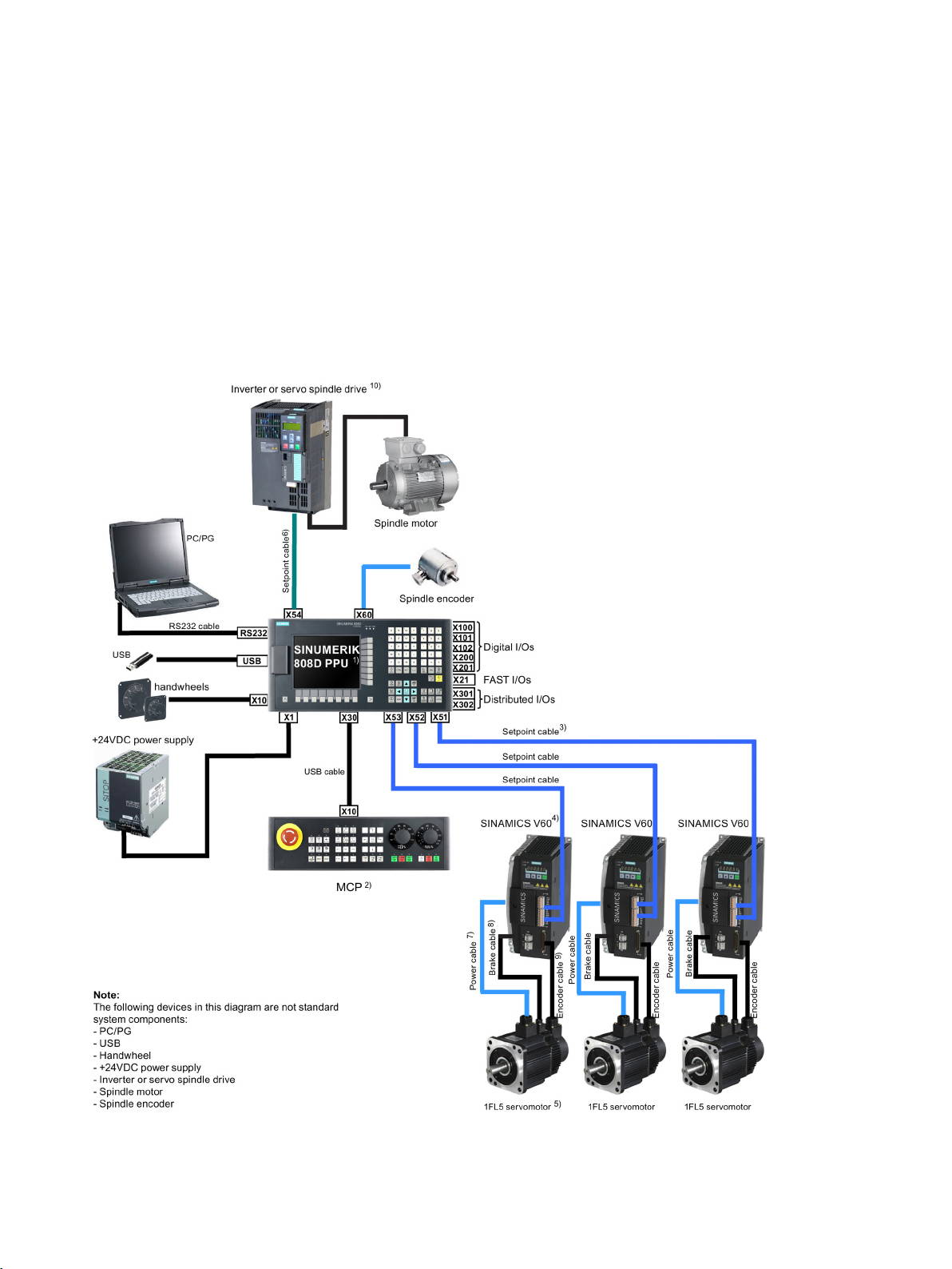
The
global market. For the turning variant, it is designed to control three axes, including two feed
axes via two pulse drive interfaces (with SINAMICS V60) and one spindle via one analog
spindle interface. For the milling variant, it is designed to control four axes, including three
feed axes via three pulse drive interfaces (with SINAMICS V60) and one spindle via one
analog spindle interface.
The following diagram shows a system configuration example for the SINUMERIK 808D
control system:
is an economic CNC solution for milling and turning machines in the
Figure 1-1 SINUMERIK 808D control system overview (taking a milling machine for an example)
Commissioning Manual
Commissioning Manual, 12/2014, 6FC5397-4EP10-0BA0
7

Delivery check
Note
Legend
Name
Order number
6FC5370-1AM00-0CA0 (Chinese)
6FC5548-0BA00-1AH0 (7 m)
6SL3210-5CC16-0UA0 (6 A)
1FL5060-0AC21-0AA0 (4 Nm, with key, without brake)
1FL5062-0AC21-0AG0 (6 Nm, without key, without brake)
1FL5066-0AC21-0AA0 (10 Nm, with key, without brake)
1FL5060-0AC21-0AH0 (4 Nm, without key, with brake)
1FL5064-0AC21-0AB0 (7.7 Nm, with key, with brake)
1FL5066-0AC21-0AH0 (10 Nm, without key, with brake)
6FC5548-0BA05-1BA0 (10 m)
6FX6002-2BR00-1AF0 (5 m)
6FX6002-2LE00-1BA0 (10 m)
For a turning machine, you need two sets of setpoint cable + SINAMICS V60 drive + motor
cable + brake cable (if necessary) + encoder cable + 1FL5 servomotor.
1) PPU141.1, turning 6FC5370-1AT00-0AA0 (English)
6FC5370-1AT00-0CA0 (Chinese)
PPU141.1, milling 6FC5370-1AM00-0AA0 (English)
2) MCP 6FC5303-0AF35-0AA0 (English)
6FC5303-0AF35-0CA0 (Chinese)
3) Setpoint cable PPU141.1 to CPM60.1 6FC5548-0BA00-1AF0 (5 m)
6FC5548-0BA00-1BA0 (10 m)
4) SINAMICS V60 Controlled Power Module
(CPM60.1)
5) 1FL5 Motor
6SL3210-5CC14-0UA0 (4 A)
6SL3210-5CC17-0UA0 (7 A)
6SL3210-5CC21-0UA0 (10 A)
1FL5060-0AC21-0AG0 (4 Nm, without key, without brake)
1FL5062-0AC21-0AA0 (6 Nm, with key, without brake)
1FL5064-0AC21-0AA0 (7.7 Nm, with key, without brake)
1FL5064-0AC21-0AG0 (7.7 Nm, without key, without brake)
1FL5066-0AC21-0AG0 (10 Nm, without key, without brake)
1FL5060-0AC21-0AB0 (4 Nm, with key, with brake)
1FL5062-0AC21-0AB0 (6 Nm, with key, with brake)
1FL5062-0AC21-0AH0 (6 Nm, without key, with brake)
1FL5064-0AC21-0AH0 (7.7 Nm, without key, with brake)
1FL5066-0AC21-0AB0 (10 Nm, with key, with brake)
6) Setpoint cable PPU141.1 to inverter or servo
spindle drive
7) Motor cable (unshielded) 6FX6002-5LE00-1AF0 (5 m)
8) Brake cable (unshielded)
9) Encoder cable (shielded) 6FX6002-2LE00-1AF0 (5 m)
6FC5548-0BA05-1AF0 (5 m)
6FC5548-0BA05-1AH0 (7 m)
6FX6002-5LE00-1BA0 (10 m)
6FX6002-2BR00-1BA0 (10 m)
10) Inverter or servo spindle drive From Siemens or a third-party manufacturer
Commissioning Manual
8 Commissioning Manual, 12/2014, 6FC5397-4EP10-0BA0

Delivery check
Check list
Component
Quantity (pieces)
Component
Quantity (pieces)
Component
Quantity (pieces)
Note
Component
Quantity (pieces)
Component
Quantity (pieces)
Component
Quantity (pieces)
Table 1- 1 PPU package
Panel Processing Unit (PPU) 1
Mounting clamps with screws 8
Connectors
Table 1- 2 MCP package
Machine Control Panel (MCP) 1
MCP connection cable (for connecting the MCP to the PPU, max. 50 cm) 1
Mounting clamps with screws 6
Pre-printed MCP strip, Milling 1 set of 6 pieces
Blank strip paper, A4 size 1
Product Information for MCP
1
• I/O connectors: 7
• 24 V power input connector: 1
Table 1- 3 CNC accessories
Setpoint cable to SINAMICS V60 (for feed axis) 2 (turning) or 3 (milling)
Setpoint cable to Siemens inverter or third-party drive (for spindle) 1
Emergency stop button is not included in our scope of delivery. You can, if necessary,
contact your local Siemens salesperson for it.
Table 1- 4 SINAMICS V60 package
SINAMICS V60 1
Getting Started
Cable clamps 2
Warranty Card 1
Table 1- 5 1FL5 motor package
1FL5 motor 1
Data sheet for 1FL5 motor 1
1
Commissioning Manual
Commissioning Manual, 12/2014, 6FC5397-4EP10-0BA0
Table 1- 6 Cables individually packaged
Motor cable (unshielded) 1
Brake cable (unshielded) 1
Encoder cable (shielded) 1
9

Delivery check
Commissioning Manual
10 Commissioning Manual, 12/2014, 6FC5397-4EP10-0BA0

2
2.1
Mounting the controller
Cut-out dimensions
Note
Figure 2-1 Cut-out dimensions (in mm)
Make sure there is enough space around the PPU and the MCP for tightening the screws in
the control cabinet.
Commissioning Manual
Commissioning Manual, 12/2014, 6FC5397-4EP10-0BA0
11
Mounting
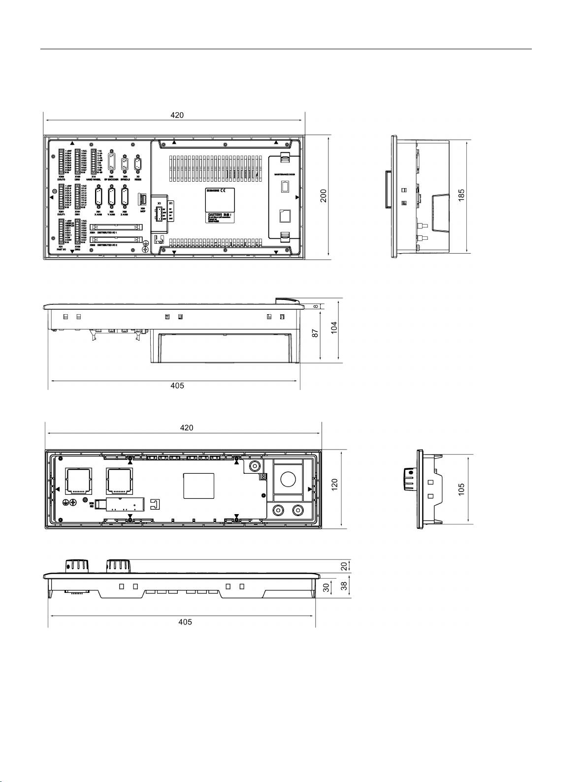
Mounting dimensions
2.1 Mounting the controller
Figure 2-2 Mounting dimensions for PPU (in mm)
Figure 2-3 Mounting dimensions for MCP (in mm)
Commissioning Manual
12 Commissioning Manual, 12/2014, 6FC5397-4EP10-0BA0

Mounting
Mounting clearance (in mm)
2.2
Mounting the drive
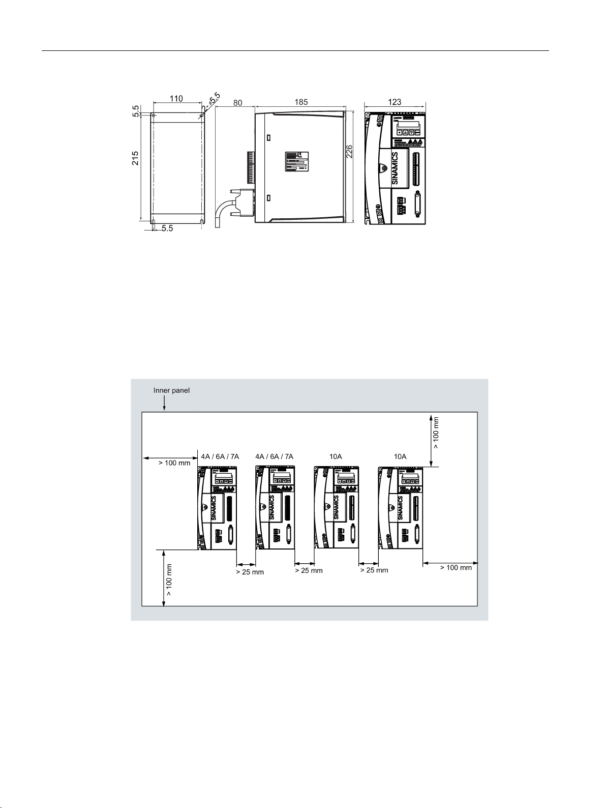
Cut-outs and mounting dimensions
2.2 Mounting the drive
To ensure easy maintenance purpose, you must provide sufficient clearance (recommended
distance: 80 mm) between the maintenance door and the cabinet wall for replacing the
battery and CF card:
Cabinet panel
①
Figure 2-4 4/6/7 A version (in mm)
Maintenance door
②
Commissioning Manual
Commissioning Manual, 12/2014, 6FC5397-4EP10-0BA0
13
Mounting
Mounting method
vertically
Minimum mounting clearance
Using the cable clamps supplied
2.2 Mounting the drive
Figure 2-5 10 A version (in mm)
With 4xM5 preassembled screws, the drive can be mounted
the cabinet. The maximum screw torque must be 2.0 Nm.
To ensure adequate cooling, as a minimum, maintain the specified clearance between
drives, one drive and another device/inner panel of the cabinet.
onto the inner panel of
Figure 2-6 Drive mounting clearance (in mm)
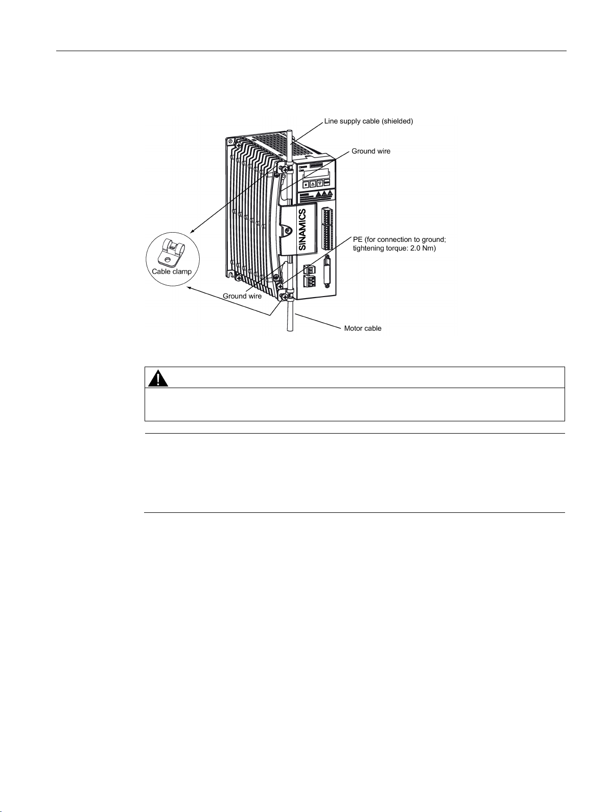
If the CE marking requirements for cables are mandatory, the line supply cable and the
motor cable used must all be shielded cables. In this case, you can use the cable clamps as
a ground connection between the cable shield and a common ground point.
Clamps can also be helpful in better fixing cables (the unshielded motor cable and the line
supply cable) in place.
Commissioning Manual
14 Commissioning Manual, 12/2014, 6FC5397-4EP10-0BA0
Mounting
CAUTION
Note
Reference
2.2 Mounting the drive
The illustration below shows you how to use the clamps to fix both cables and to make a
shield connection with the cable.
Figure 2-7 Cable fixing with two cable clamps
Make sure that the clamp for fixing the shielded motor cable has a good contact with the
cable shield.
Siemens does not provide the shielded motor cable. Please prepare the shielded motor
cable by yourselves for CE certification.
After the installation, it is recommended that the terminal screws should be checked to
ensure that they are tight.
For further information about the drive mounting, refer to SINAMICS V60
Getting Started
.
Commissioning Manual
Commissioning Manual, 12/2014, 6FC5397-4EP10-0BA0
15

Mounting
2.3
Mounting the motor
Mounting dimensions (mm)
Motor type
A (in mm)
B (in mm)
Note
Reference
2.3 Mounting the motor
4 Nm 163 (205) 80
6 Nm 181 (223) 90
7.7 Nm 195 (237) 112
10 Nm 219 (261) 136
Value in brackets is the length of a motor with a built-in brake unit.
Motors with plain shaft have the same dimensions.
For further information about the motor, refer to
1FL5 Motor Technical Data
.
Commissioning Manual
16 Commissioning Manual, 12/2014, 6FC5397-4EP10-0BA0
3
3.1
Interface overview
Interface overview on the Panel Processing Unit (PPU)
NOTICE
The + 24 V and M signals of X200 must be connected; otherwise, the communication
between the PPU and the drives does not function as it should.
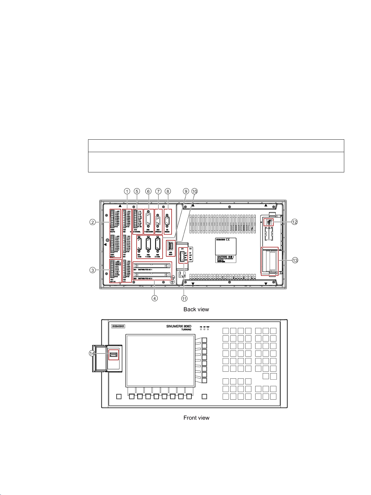
Figure 3-1 Interface layout
Commissioning Manual
Commissioning Manual, 12/2014, 6FC5397-4EP10-0BA0
17
Connecting
Legend
Interface
Comment
Rear
Front
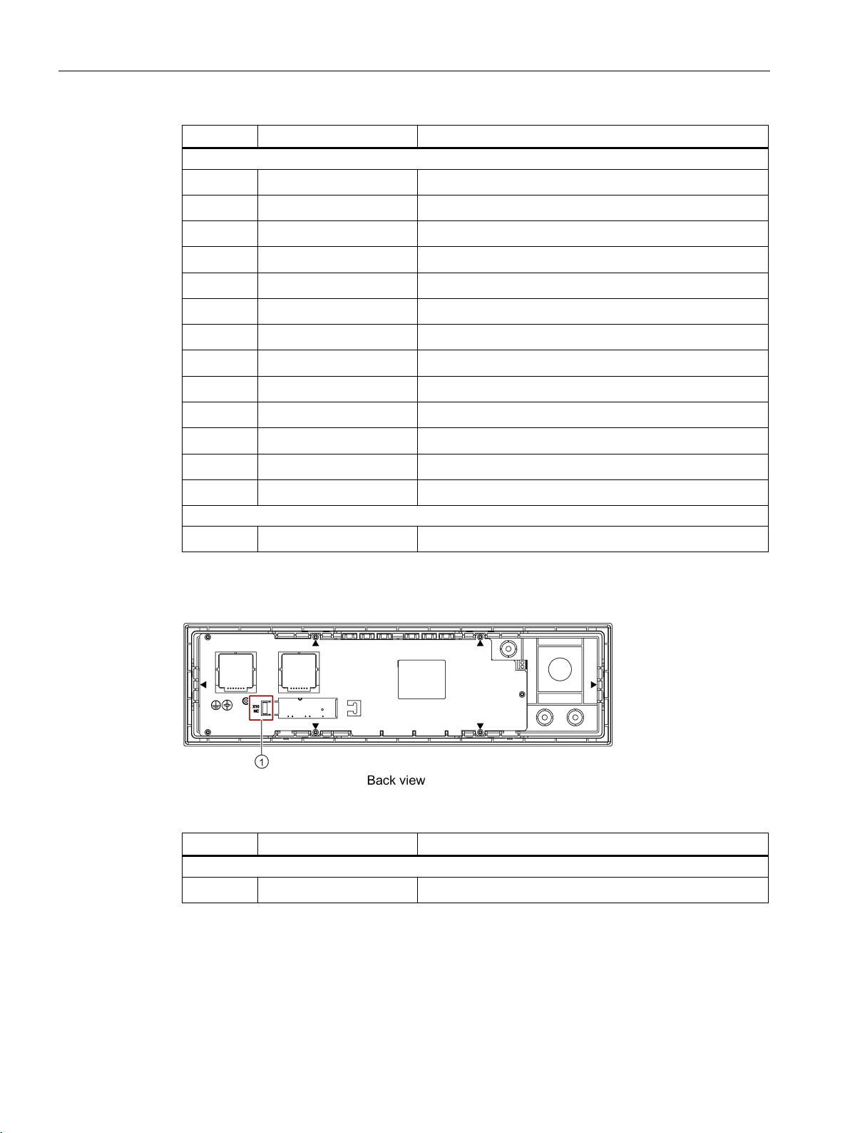
Interface overview on the Machine Control Panel (MCP)
Legend
Interface
Comment
Rear
3.2 Connecting the battery
①
②
③
④
⑤
⑥
⑦
⑧
⑨
⑩
⑪
⑫
⑬
⑭
X100, X101, X102 Digital inputs
X200, X201 Digital outputs
X21 FAST I/O
X301, X302 Distributed I/O
X10 Hand-wheel inputs
X60 Spindle encoder interface
X54 Analog spindle interface
X2 RS232 interface
X51, X52, X53 Pulse drive interfaces
X30 USB interface, for connection with the MCP
X1 Power supply interface, +24V DC power supply
- Battery interface
- Slot for the System CompactFlash Card (CF card)
- USB interface
Figure 3-2 Interface layout
①
X10 USB interface, for connection with the PPU
Commissioning Manual
18 Commissioning Manual, 12/2014, 6FC5397-4EP10-0BA0
Connecting
3.2
Connecting the battery
must
Note
Note
Battery
do not
6FC5247-0AA18-0AA0
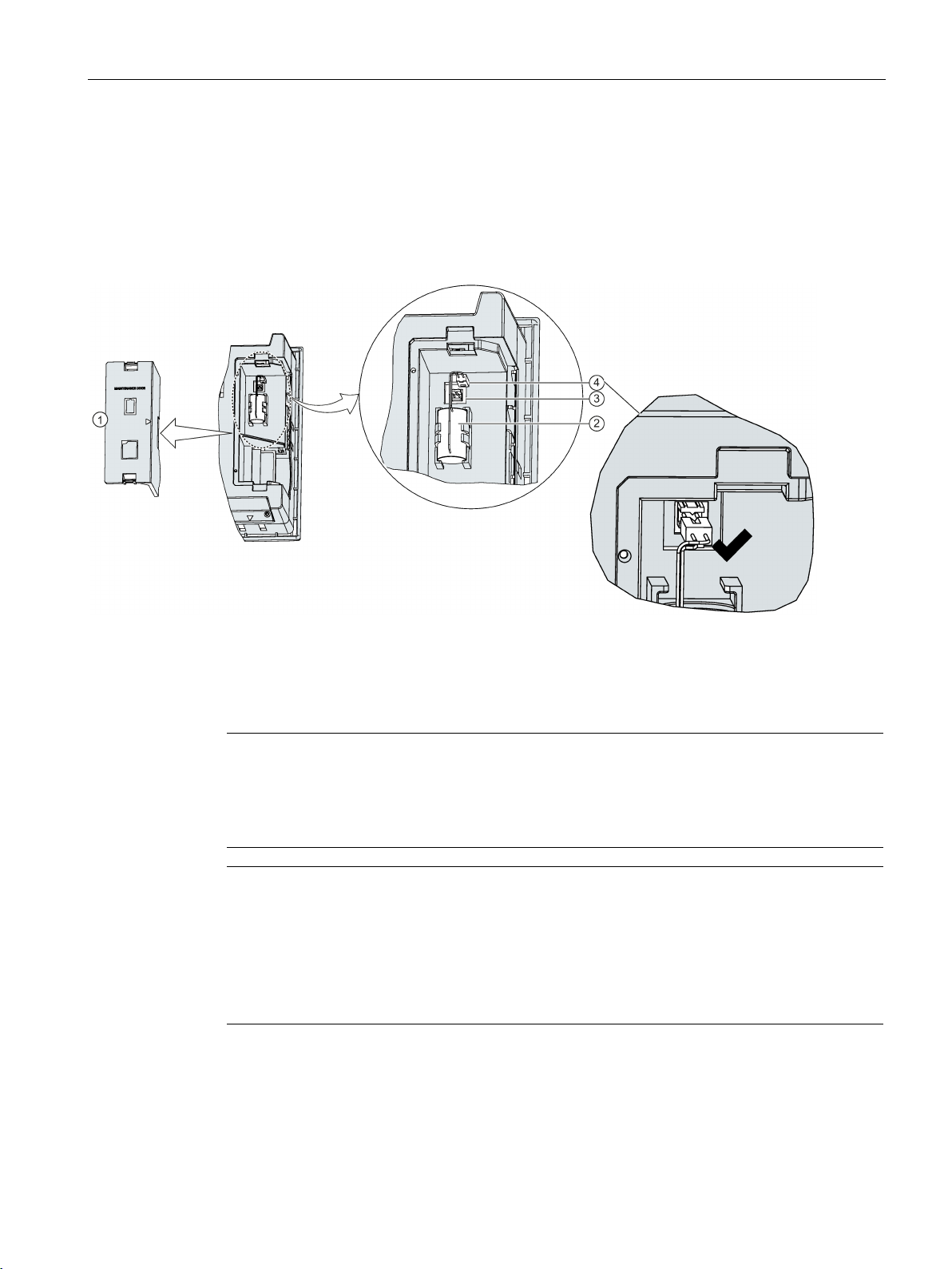
3.2 Connecting the battery
A battery has been pre-assembled on the back cover of the PPU.
The battery is not connected when delivered. You
plug the battery connector into the
battery interface by yourself before switching the controller on. You can access it after
removing the maintenance door:
Maintenance door
①
Battery
②
Battery interface
③
Battery connector
④
When connecting the battery, ensure that the groove is at the upper side; otherwise, the
alarm "NCK battery alarm" will be output after you switch on the controller, and you could
lose your data after an unexpected power failure if you do not insert the battery connector
correctly.
Life time: 3 years
Replacement:
replace the battery when the controller is switched off; otherwise, your
data can be lost.
Order number:
Commissioning Manual
Commissioning Manual, 12/2014, 6FC5397-4EP10-0BA0
.
19
Connecting
3.3
Connecting according to the default PLC program
Connecting the digital inputs and outputs
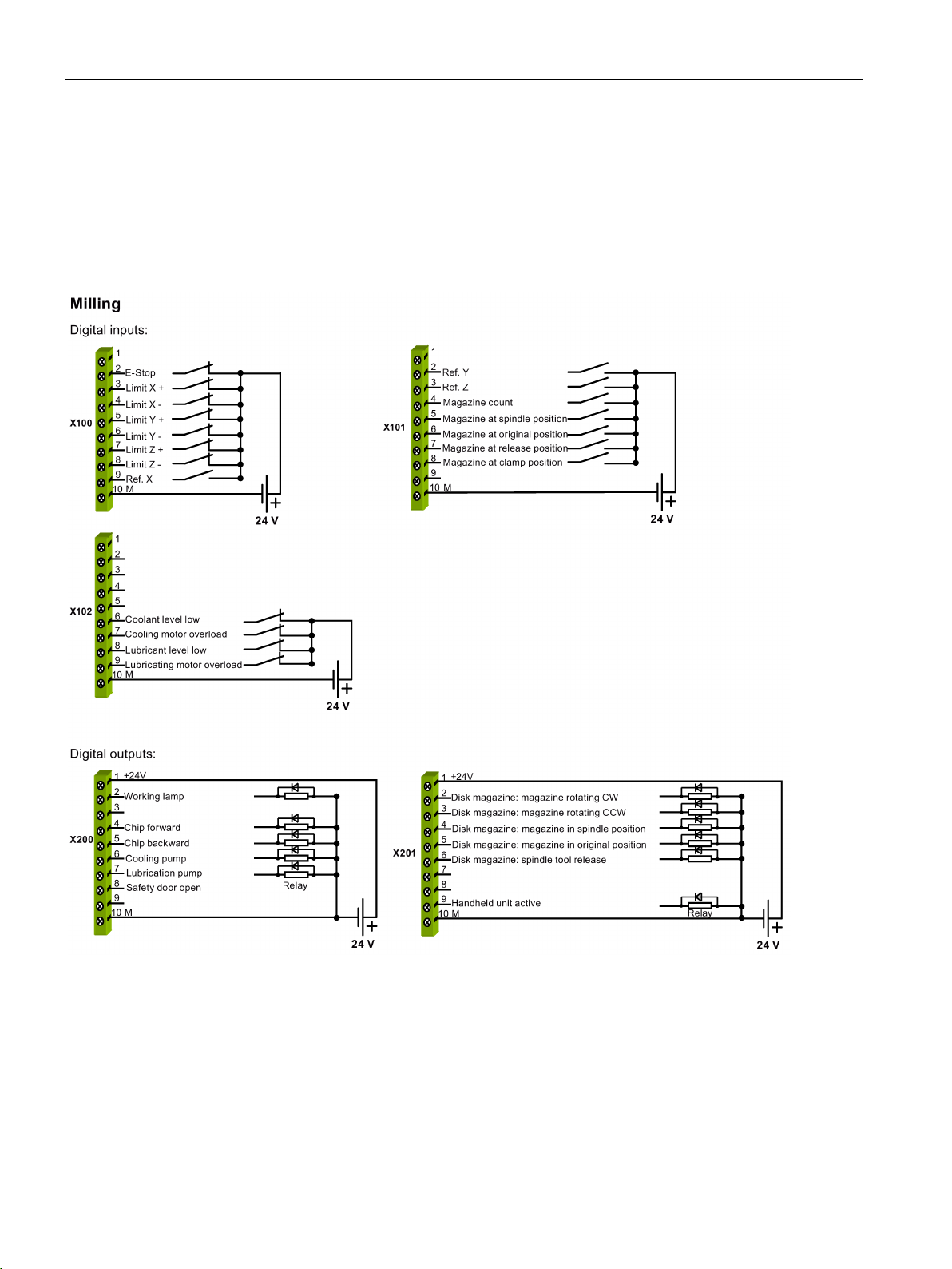
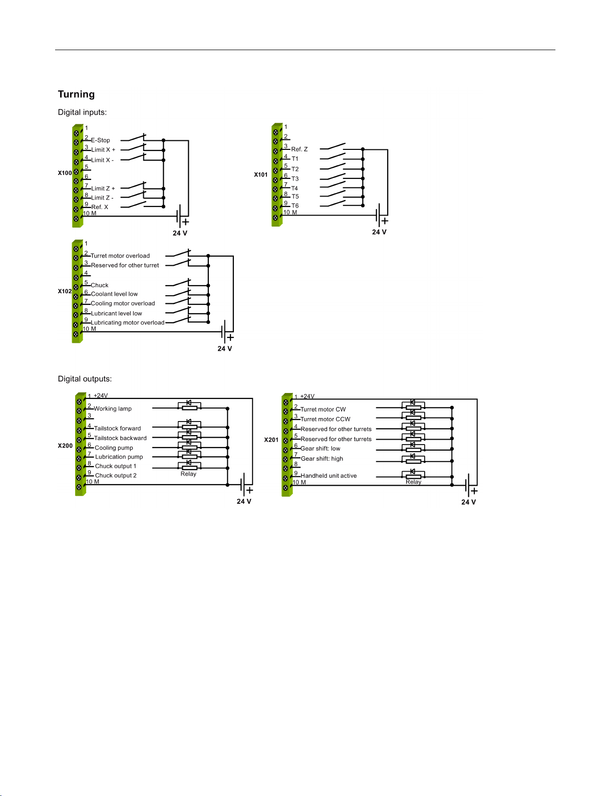
3.3 Connecting according to the default PLC program
The SINUMERIK 808D has integrated with a default PLC application. If you perform the
commissioning work with the default PLC application, perform wiring as follows.
Figure 3-3 Connecting the digital inputs and outputs (Milling)
Commissioning Manual
20 Commissioning Manual, 12/2014, 6FC5397-4EP10-0BA0
Connecting
3.3 Connecting according to the default PLC program
Figure 3-4 Connecting the digital inputs and outputs (Turning)
Commissioning Manual
Commissioning Manual, 12/2014, 6FC5397-4EP10-0BA0
21

Connecting
Connecting the distributed I/O
Connecting the SINAMICS V60 (take X51: axis X for an example)
3.3 Connecting according to the default PLC program
Figure 3-5 Connecting the distributed I/O
Figure 3-6 Connecting the SINAMICS V60 (X51: axis X)
Commissioning Manual
22 Commissioning Manual, 12/2014, 6FC5397-4EP10-0BA0
Connecting
Note
Filter
6SN1111-0AA01-1BA1
Note
Circuit breaker
You can install a mains linear breaker (rated current: 15 A for 7 A or 10 A version of the drive
Connecting the inverter or the servo spindle drive
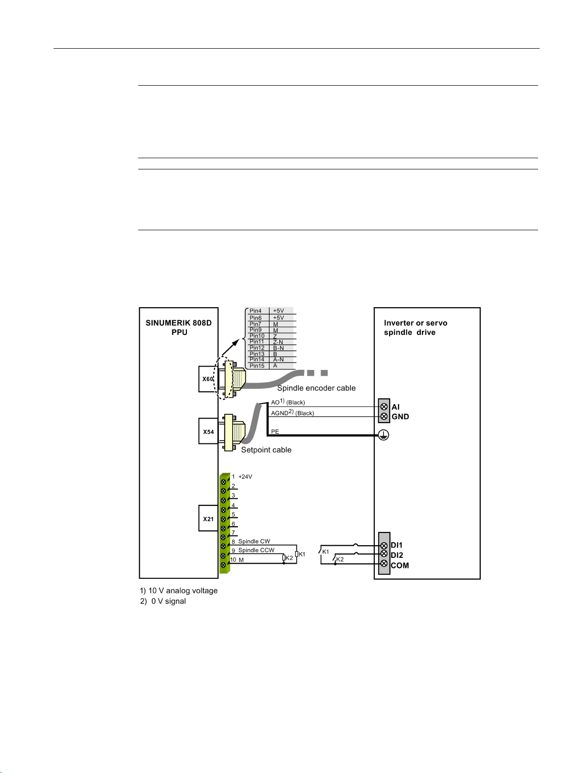
3.3 Connecting according to the default PLC program
A line filter (rated current: 16 A, protection level: IP20) is required so that the system can
pass the CE certification (radiated emission test or conducted emission test). The order
number of Siemens recommended filter is
.
and 10 A for 4 A or 6 A version of the drive; rated voltage: 250 VAC) to protect the system.
Figure 3-7 Connecting the inverter or the servo spindle drive (unipolar)
Commissioning Manual
Commissioning Manual, 12/2014, 6FC5397-4EP10-0BA0
23
Connecting
Note
must
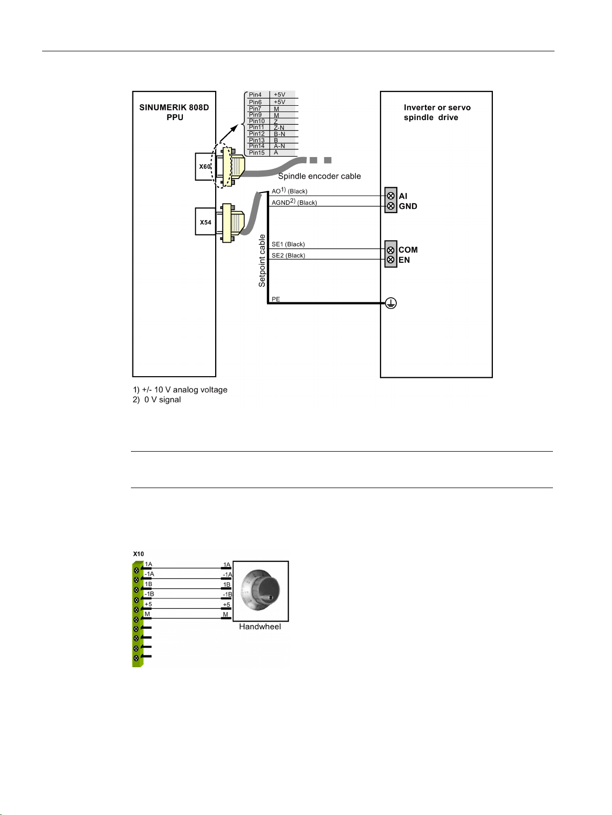
Connecting the handwheel
3.3 Connecting according to the default PLC program
Figure 3-8 Connecting the inverter or the servo spindle drive (bipolar)
Cables for connecting X21
Figure 3-9 Connecting the handwheel
be shielded ones.
Commissioning Manual
24 Commissioning Manual, 12/2014, 6FC5397-4EP10-0BA0
Connecting
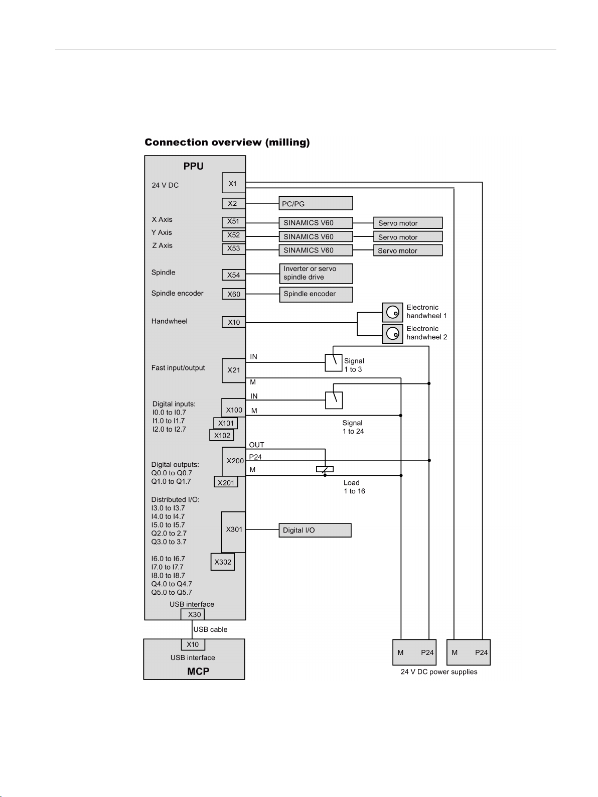
3.4
Connection Overview
3.4 Connection Overview
Commissioning Manual
Commissioning Manual, 12/2014, 6FC5397-4EP10-0BA0
25

Connecting
Note
For the turning variant, connection to X52 is optional and depends upon whether you use the
l linear axis, connect X52 to a SINAMICS V60 which connects to a
3.4 Connection Overview
software option "additional axis". If you desire to configure the control system to control a
rotary axis or an additiona
servo motor.
Commissioning Manual
26 Commissioning Manual, 12/2014, 6FC5397-4EP10-0BA0

4
DANGER
Carrying out of repairs
4.1
Switching on controller
Before switching on
Switching on
POK
RDY
TEMP
S-run
RDY/JOG
ERR
Anywhere in the automation equipment where faults might cause physical injury or major
material damage, in other words, where faults could be dangerous, additional external precautions must be taken, or facilities must be provided, that guarantee or enforce a safe
operational state, even when there is a fault (e.g. using an independent limit value switch,
mechanical locking mechanisms, EMERGENCY STOP/EMERGENCY OFF devices).
Make sure that:
● You have finished the mechanical installation of the whole system based on the
● You have completed the wirings of the whole system according to the information
Do as follows:
1. Power on the mains supply.
2. When the NC enters the main screen, check the NC normal status according to the status
3. Check the drive normal status:
information included in the chapter "Mounting (Page 11)" or the
Manual
included in the chapter "Connecting (Page 17)" (if you use the default PLC program) or
the
LEDs on the PPU.
For detailed information about the status LEDs, refer to the section "Status LEDs
(Page 30)".
– "
– LED "
– LED "
For detailed information about the SINAMICS V60 drives, refer to the
Getting Started
.
Electrical Installation Manual
: green
: green
: unlit
" is displayed.
": green
": dark
.
.
Mechanical Installation
SINAMICS V60
Commissioning Manual
Commissioning Manual, 12/2014, 6FC5397-4EP10-0BA0
27
Switching on and preparing for commissioning
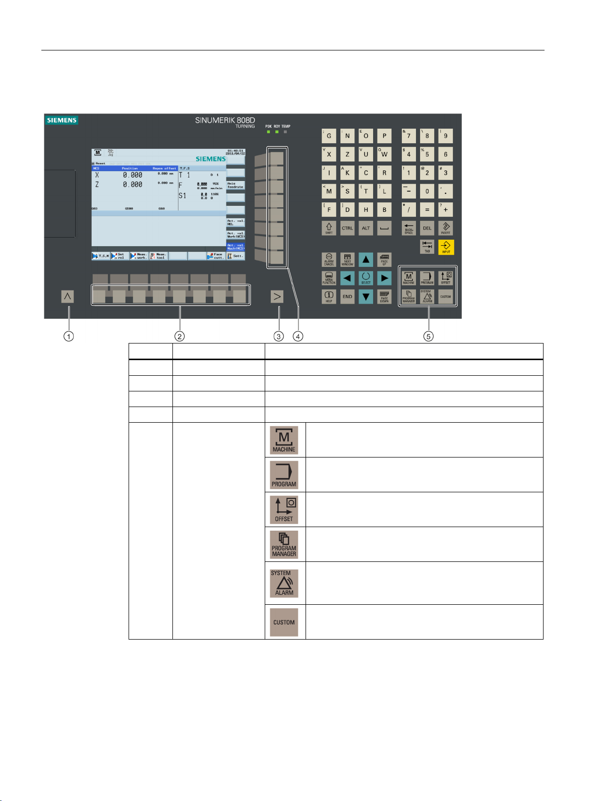
4.2
PPU keyboard function
Legend
Name
Description
①
Return key
Returns to higher level menu
②
③
Extension key
Reserved. No function
④
Vertical softkeys
Call corresponding menu functions
MACHINE
PROGRAM
OFFSET
PROGRAM MANAGER
ALARM
SHIFT
SYSTEM
CUSTOM
4.2 PPU keyboard function
Horizontal softkeys Call corresponding menu functions
⑤
Operating area keys
Opens the "
Opens the "
Opens the "
Opens the "
• Opens the "
• Combines with the <
"
Opens the "
" area
" operating area
" operating area
" operating area
" operating area
" operating area
> key to open the
" operating area
Commissioning Manual
28 Commissioning Manual, 12/2014, 6FC5397-4EP10-0BA0

Switching on and preparing for commissioning
4.3
MCP mode changeover
JOG
Ref
Point
AUTO
MDA
Legend
Name
Description
Ref. Point
JOG
AUTO
MDA
RESET
4.3 MCP mode changeover
Use the machine control panel (MCP) to make changeover between the
mode, the
mode and the
mode.
The MCP key layout is shown below:
①
Mode navigation
keys
Enters the
Enters the
mode for reference point approach
mode (manual operation)
mode, the
②
③
④
Enters the
Enters the
matic execution)
Incremental feed
keys
Axis traversing keys Move an axis (X, Y, Z)
key
• Resets NC programs
• Cancels alarms
Axis traverses at the increment of 1
Axis traverses at the increment of 10
Axis traverses at the increment of 100
mode (automatic operation)
mode (manual program input and auto-
Commissioning Manual
Commissioning Manual, 12/2014, 6FC5397-4EP10-0BA0
29
Switching on and preparing for commissioning
4.4
Status LEDs
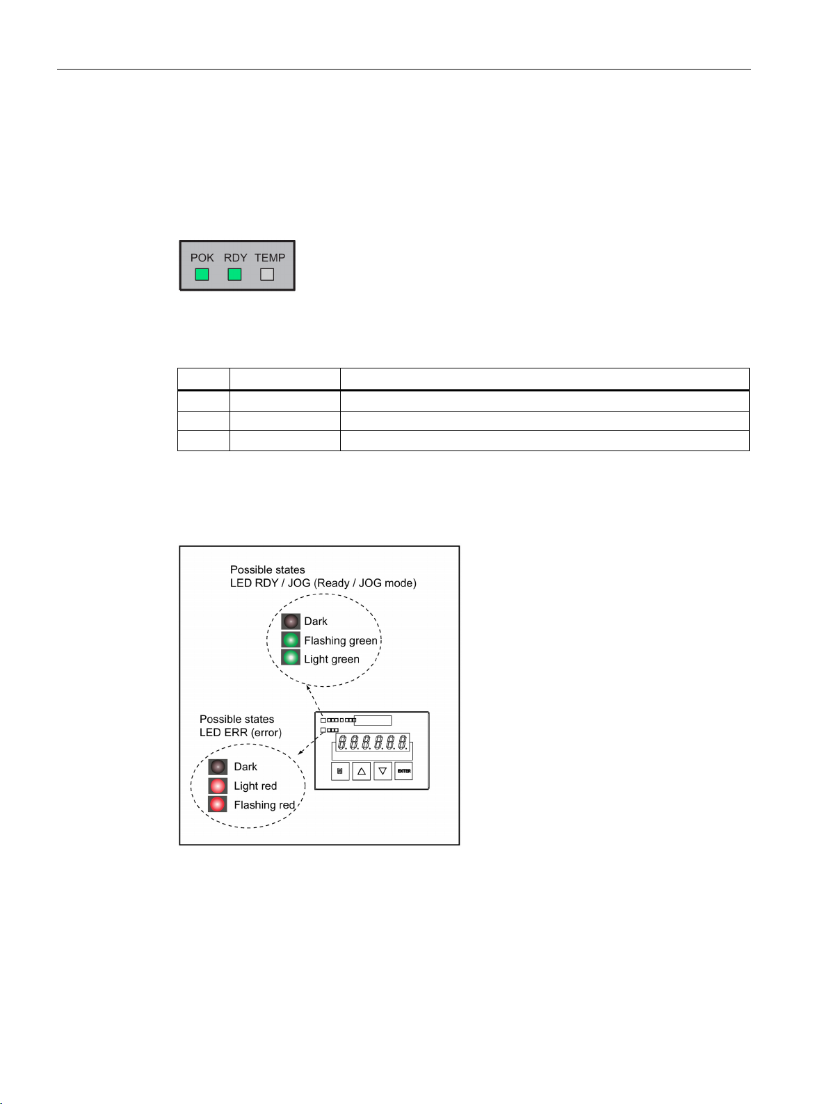
LEDs on the PPU
LED
Color
Significance
LEDs on the SINAMICS V60 drives
4.4 Status LEDs
The following LEDs are installed on the SINUMERIK 808D PPU.
The individual LEDs and their functions are described in the table below.
Table 4- 1 Status and error displays
POK Green Power supply is OK.
RDY Green Ready for operation
TEMP Yellow Temperature exceeds the limit
For more information, refer to error description in the
Figure 4-1 SINAMICS V60 status LEDs
SINUMERIK 808D Diagnostics Manual
.
Commissioning Manual
30 Commissioning Manual, 12/2014, 6FC5397-4EP10-0BA0
 Loading...