

Page 1

Operation and Programming 08/2003 Edition
sinumerik
SINUMERIK 802S base line
SINUMERIK 802C base line
Milling
Page 2

Page 3

SINUMERIK 802S base line
SINUMERIK 802C base line
Operation and Programming
Introduction
Turning On, Reference
Point Approach
1
2
Milling
Setup
Manually Operated Mode
Automatic Mode
Part Programming
Services and Diagnosis
Programming
3
4
5
6
7
8
Valid for
Control system Software version
SINUMERIK 802S base line 4
SINUMERIK 802C base line 4
2003.08 Edition
Cycles
9
Page 4

SINUMERIK
®
Documentation
Key to editions
The editions listed below have been published prior to the current edition.
The column headed “Note” lists the amended sections, with reference to the previous edition.
Marking of edition in the “Note” column:
A ... ... New documentation.
B ... ... Unchanged reprint with new order number.
C ... ... Revised edition of new issue.
Edition Order No. Note
1999.02 6FC5598-2AA10-0BP1 A
2000.04 6FC5598-3AA10-0BP1 A
2002.01 6FC5598-3AA10-0BP2 C
2003.08 6FC5598-4AA11-0BP0 A
Trademarks
SIMATIC
®
, SIMATIC HMI®, SIMATIC NET®, SIMODRIVE®, SINUMERIK®, and SIMOTION® are registered
trademarks of SIEMENS AG.
Other names in this publication might be trademarks whose use by a third party for his own purposes may violate
the registered holder.
Copyright Siemens AG 2003. All right reserved
The reproduction, transmission or use of this document or its contents is not permitted without express written authority. Offenders will
be liable for damages. All rights, including rights created by patent
grant or registration of a utility model, are reserved.
Exclusion of liability
We have checked that the contents of this document correspond to
the hardware and software described. Nonetheless, differences
might exist and we cannot therefore guarantee that they are completely identical. The information contained in this document is reviewed regularly and any necessary changes will be included in the
next edition. We welcome suggestions for improvement.
© Siemens AG, 2003
Subject to technical changes without notice.
Siemens-Aktiengesellschaft. SINUMERIK 802S/802C base line
Page 5

Safety Guidelines
This Manual contains notices intended to ensure your personal safety , as well
as to protect products and connected equipment against damage. Safety
notices are highlighted by a warning triangle and presented in the following
categories depending on the degree of risk involved:
!
Indicates an imminently hazardous situation which, if not avoided, will result in
!
Indicates a potentially hazardous situation which, if not avoided, could result in
!
Used with safety alert symbol indicates a potentially hazardous situation which,
Used without safety alert symbol indicates a potentially hazardous situation
Danger
death or serious injury or in substantial property damage.
Warning
death or serious injury or in substantial property damage.
Caution
if not avoided, may result in minor or moderate injury or in property damage.
Caution
which, if not avoided, may result in property damage.
Indicates important information relating to the product or highlights part of the
Qualified person
Proper use
The unit may be used only for the applications described in the catalog or the
!
This product must be transported, stored and installed as intended, and
Please observe the following:
Notice
documentation for special attention.
The unit may only be started up and operated by qualified person or persons.
Qualified personnel as referred to in the safety notices provided in this
document are those who are authorized to start up, earth and label units,
systems and circuits in accordance with relevant safety standards.
Warning
technical description, and only in combination with the equipment, components
and devices of other manufacturers as far as this is recommended or p ermitted
by Siemens.
maintained and operated with care to ensure that it functions correctly and
safely.
Page 6

Page 7
Contents
Contents
SINUMERIK 802S/C base line Operator Panel OP
1. Introduction
1.1 Screen Layout 1-1
1.2 Operating areas 1-4
1.3 Overview of the most important softkey functions 1-5
1.4 Pocket calculator 1-6
1.5 Basic principles 1-12
III
1-1
2. Turning On and Reference Point Approach
2-1
3. Setup
3.1 Entering tools and tool offsets 3-1
3.1.1 Creating a new tool 3-3
3.1.2 Tool compensation data 3-4
3.1.3 Determining the tool offsets 3-5
3.2 Entering/modifying zero offsets 3-7
3.2.1 Determining the zero offset 3-9
3.3 Programming the setting data – “Parameters” operating area 3-11
3.4 R parameters – “Parameters” operating area 3-13
3-1
4. Manually Operated Mode
4.1 Jog mode – “Machine” operating area 4-1
4.1.1 Assigning handwheels 4-4
4.2 MDA Mode (Manual Data Input) – “Machine” operating area 4-5
5. Automatic Mode
5.1 Selecting/starting a part program – “Machine” operating area 5-4
5.2 Block search – “Machine” operating area 5-5
5.3 Stopping/cancelling a part program – “Machine” operating area 5-6
5.4 Repositioning after interruption 5-7
5.5 Program execution from external (RS232 interface) 5-8
5.6 Teach In 5-9
4-1
5-1
6. Part Programming
6.1 Entering a new program – “Program” operating area 6-3
6.2 Editing part programs – “Program” operating area 6-4
6.3 Programming support 6-7
6.3.1 Vertical menu 6-7
6.3.2 Cycles 6-8
6.3.3 Contour 6-9
6.3.4 Free softkey assignment 6-24
6-1
7. Services and Diagnosis
7.1 Data transfer via the RS232 Interface 7-1
7.1.1 Interface parameters 7-4
7.1.2 Special functions 7-5
7.1.3 Interface parameterization 7-5
7.2 Diagnosis and start-up – “Diagnostics” operating area 7-7
7-1
8. Programming
8.1 Fundamentals of NC programming 8-1
8.1.1 Program structure 8-1
8.1.2 Word structure and address 8-2
8.1.3 Block structure 8-3
8.1.4 Character set 8-4
8.1.5 Overview of instructions 8-5
8-1
SINUMERIK 802S/C base line
Operation and Programming Milling
I
Page 8
Contents
8.2 Position data 8-12
8.2.1 Plane selection: G17 to G19 8-12
8.2.2 Absolute/incremental dimensions: G90, G91 8-13
8.2.3 Metric/inch dimensions: G71, G70 8-14
8.2.4 Programmable zero offset and rotation: G158, G258, G259 8-15
8.2.5 Workpiece clamping - settable zero offset: G54 to G57, G500, G53 8-17
8.3 Axis movements 8-19
8.3.1 Linear interpolation at rapid traverse: G0 8-19
8.3.2 Linear interpolation at feedrate: G1 8-20
8.3.3 Circular interpolation: G2, G3 8-21
8.3.4 Circular interpolation via intermediate point: G5 8-25
8.3.5 Thread cutting with constant lead: G33 8-26
8.3.6 Tapping with compensating chuck: G63 8-27
8.3.7 Thread interpolation: G331, G332 8-28
8.3.8 Fixed-point approach: G75 8-29
8.3.9 Reference point approach: G74 8-29
8.3.10 Feedrate F 8-30
8.3.11 Feed overrride for circles: G900, G901 8-31
8.3.12 Exact stop / continuous-path operation: G9, G60, G64 8-32
8.3.13 Dwell time: G4 8-34
8.4 Spindle movements 8-35
8.4.1 Spindle speed S, directions of rotation 8-35
8.4.2 Spindle speed limitation: G25, G26 8-36
8.4.3 Spindle positioning: SPOS 8-36
8.5 Rounding, chamfer 8-37
8.6 Tool and tool offset 8-39
8.6.1 General notes 8-39
8.6.2 Tool T 8-40
8.6.3 Tool offset number D 8-41
8.6.4 Selection of tool radius offset: G41, G42 8-44
8.6.5 Behavior at corners: G450, G451 8-46
8.6.6 Tool radius compensation OFF: G40 8-48
8.6.7 Special cases of tool radius compensation 8-49
8.6.8 Example of tool radius compensation 8-51
8.7 Miscellaneous function M 8-52
8.8 Arithmetic parameters R 8-53
8.9 Program branches 8-55
8.9.1 Labels - destination for program branches 8-55
8.9.2 Unconditional program branches 8-56
8.9.3 Conditional branches 8-57
8.9.4 Example of program with branches 8-59
8.10 Subroutine technique 8-60
9. Cycles
9.1 General information about standard cycles 9-1
9.1.1 Overview of cycles 9-1
9.1.2 Error messages and error handling cycles 9-2
9.2 Drilling cycles 9-4
9.2.1 Drilling, spot facing - LCYC82 9-4
9.2.2 Deep hole drilling - LCYC83 9-6
9.2.3 Tapping without compensating chuck - LCYC84 9-10
9.2.4 Tapping with compensating chuck - LCYC840 9-13
9.2.5 Boring - LCYC85 9-15
9.3 Drilling patterns 9-17
9.3.1 Drilling a row of holes - LCYC60 9-17
9.3.2 Hole circle - LCYC61 9-21
9.4 Milling cycles 9-24
9.4.1 Cutting square pockets, slots and circular pockets - LCYC75 9-24
II
SINUMERIK 802S/C base line
Operation and Programming
9-1
Milling
Page 9
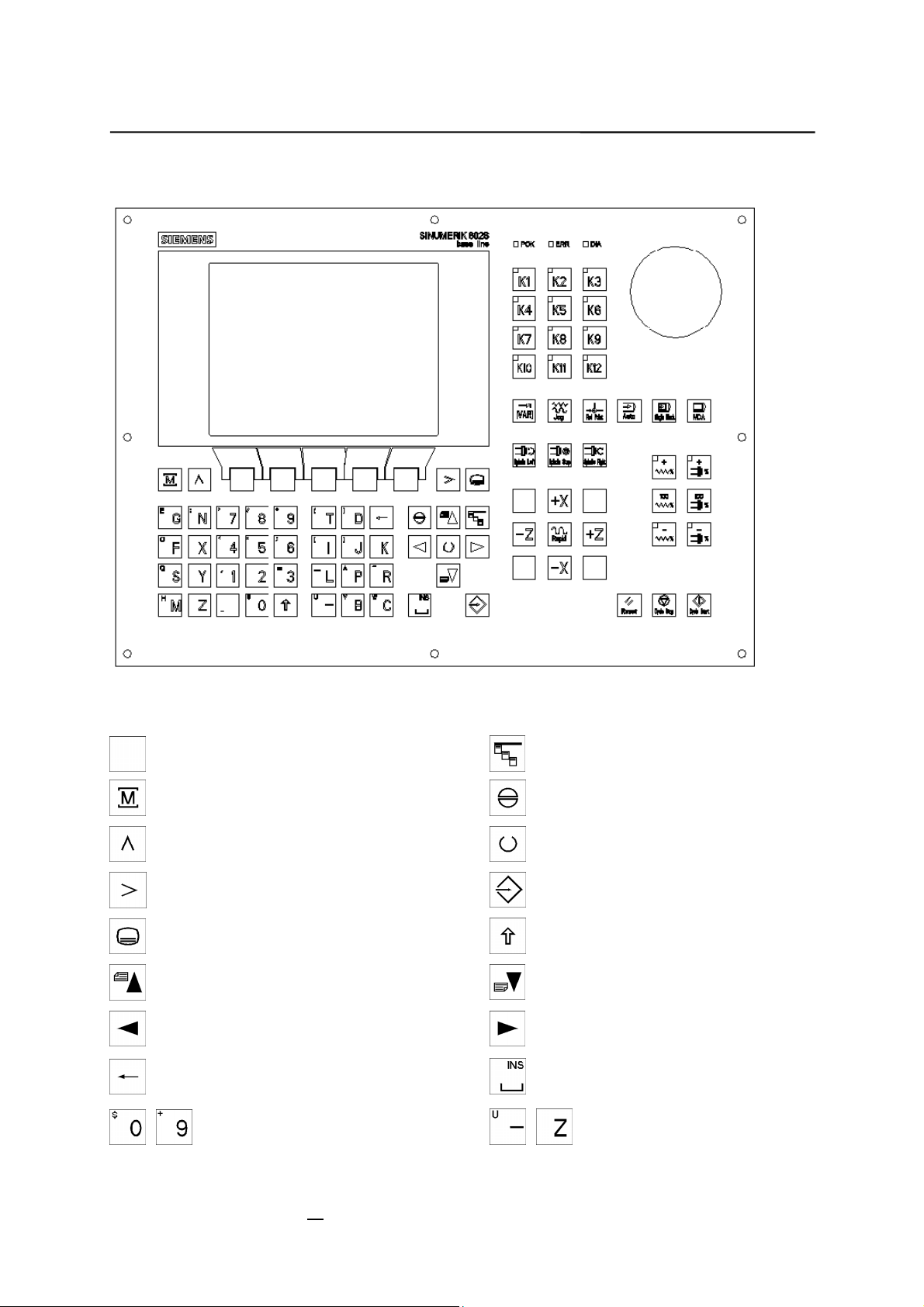
SINUMERIK 802S/C base line Operator Panel OP
Contents
NC keyboard area (left side):
Softkey
Machine area key
Recall key
ETC key
Area switchover key
Cursor UP
with shift: page up
Cursor LEFT
Delete key (backspace)
Numerical keys shift for
alternative assignment
Vertical menu
Acknowledge alarm
Selection key/toggle key
ENTER / input key
Shift key
Cursor DOWN
with shift: page down
Cursor RIGHT
SPACE (INSERT)
Alphanumeric keys shift for
alternative assignment
SINUMERIK 802S/C base line
Operation and Programming Milling
III
Page 10
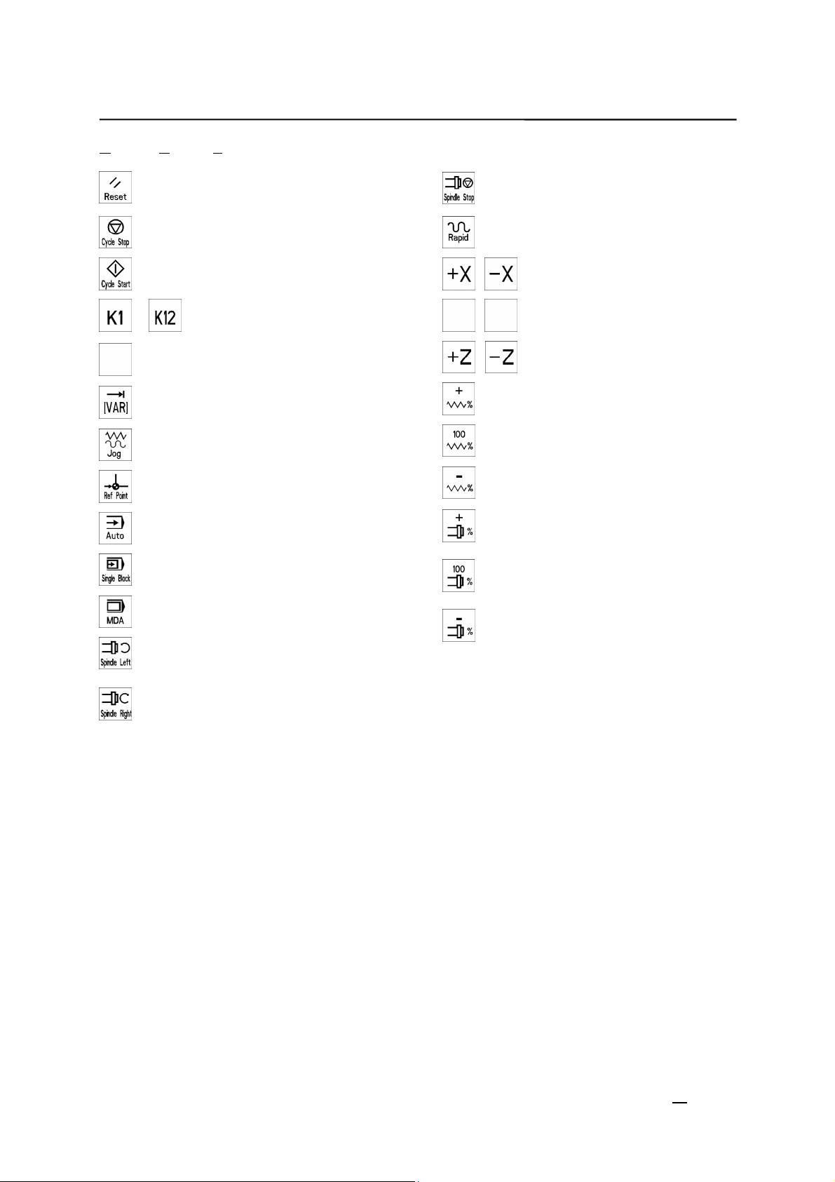
Contents
Machine Control Panel area (right side):
RESET
NC STOP
NC START
User-defined key with LED
…
User-defined key without LED
INCREMENT
JOG
REFERENCE POINT
AUTOMATIC
SINGLE BLOCK
SPINDLE STOP
RAPID TRAVERSE OVERLAY
X axis
Y axis
+Y -Y
Z axis
Feedrate override plus with LED
Feedrate override 100% without
LED
Feedrate override minus with LED
Spindle speed override plus with
LED
Spindle speed override 100%
without LED
MANUAL DATA
SPINDLE START LEFT
Counterclockwise direction
SPINDLE START RIGHT
Clockwise direction
Spindle speed override minus with
LED
IV
SINUMERIK 802S/C base line
Operation and Programming
Turning
Page 11
Introduction
1.1 Screen Layout
1
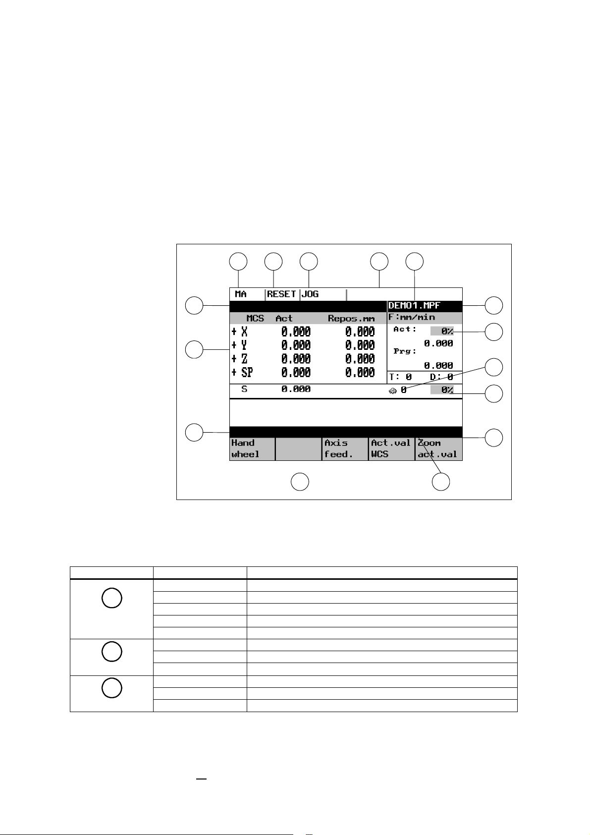
Fig.1-1 Screen layout
The abbreviations on the screen stand for the following:
Table 1–1 Explanation of display elements
Display Element Abbreviation Meaning
MA Machine
Active operating
area
Program status
Operating mode
PA Parameter
PR Programming
DI Services
DG Diagnosis
STOP Programm stopped
RUN Program running
RESET Program aborted
Jog Manual traverse
MDA Manual input with automatic function
Auto Automatic
SINUMERIK 802S/C base line
Operation and Programming Milling
1-1
Page 12
Introduction
Display Element Abbreviation Meaning
SKP Skip block
Program blocks marked by a slash in front of the block
number are ignored during program execution.
DRY Dry run feed
Traversing movements are executed at the feed specified in
the Dry Run Feed setting data.
ROV Rapid traverse override
The feed override also applies to rapid feed mode.
SBL Single block with stop after each block
When this function is active, the part program blocks are
processed separately in the following manner:
Each block is decoded separately, the program is stopped at
Status display
Operational
message
M1 Programmed stop
PRT Program test
1…1000
INC
1
2
3
4
5
6
7
8
9
10
11
12
13
14
15
16
17
18
19
20
21
22
23
the end of each block. The only exception are thread blocks
without dry run feed. In this case, the program is stopped
only when the end of the current thread block is reached.
SBL can only be selected in the RESET state.
When this function is active, the program is stopped at each
block in which the miscellaneous function M01 is
programmed.
In this case, the message “5 stop M00/M01 active” appears
on the screen.
Incremental mode
If the control is in the Jog mode, incremental dimension is
displayed instead of the active program control function.
Stop: No NC Ready
Stop: EMERGENCY STOP active
Stop: Alarm active with stop
Stop: M0/M01 sctive
Stop: Block ended in SBL mode
Stop: NC STOP active
Wait: Read-in enable missing
Wait: Feed enable missing
Wait: Dwell time active
Wait: Auxiliary function acknowl. missing
Wait: Axis enable missing
Wait: Exact stop not reached
Wait: For spindle
Wait: Feed override to 0%
Stop: NC block incorrect
Wait: Block search active
Wait: No spindle enable
Wait: Axis feed value 0
Program name
1-2
SINUMERIK 802S/C base line
Operation and Programming
Milling
Page 13
Introduction
Display Element Abbreviation Meaning
Alarm line
Working window
Recall symbol
Menu extension
The alarm line is only displayed if an NC or PLC alarm is
active. The alarm line contains the alarm number and reset
criterion of the most recent alarm.
Working window and NC display
This symbol is displayed above the softkey bar when the
operator is in a lower-level menu.
When the Recall key is pressed, you can return to the nexthigher menu without saving data.
ETC is possible If this symbol appears above the softkey
bar, further menu functions are provided. These functions
can be activated by the ETC key.
Softkey bar
If this symbol is displayed above the softkey bar, further
Vertical menu
menu functions are provided. When the VM key is pressed,
these functions appear on the screen and can be selected
by Cursor UP and Cursor DOWN.
Here the current actual feedrate override is shown.
Feedrate
override
Gear box
Spindel speed
override
Here the current spindle gear stage 1…5 is shown.
Here the current spindel speed override is shown.
SINUMERIK 802S/C base line
Operation and Programming Milling
1-3
Page 14
Introduction
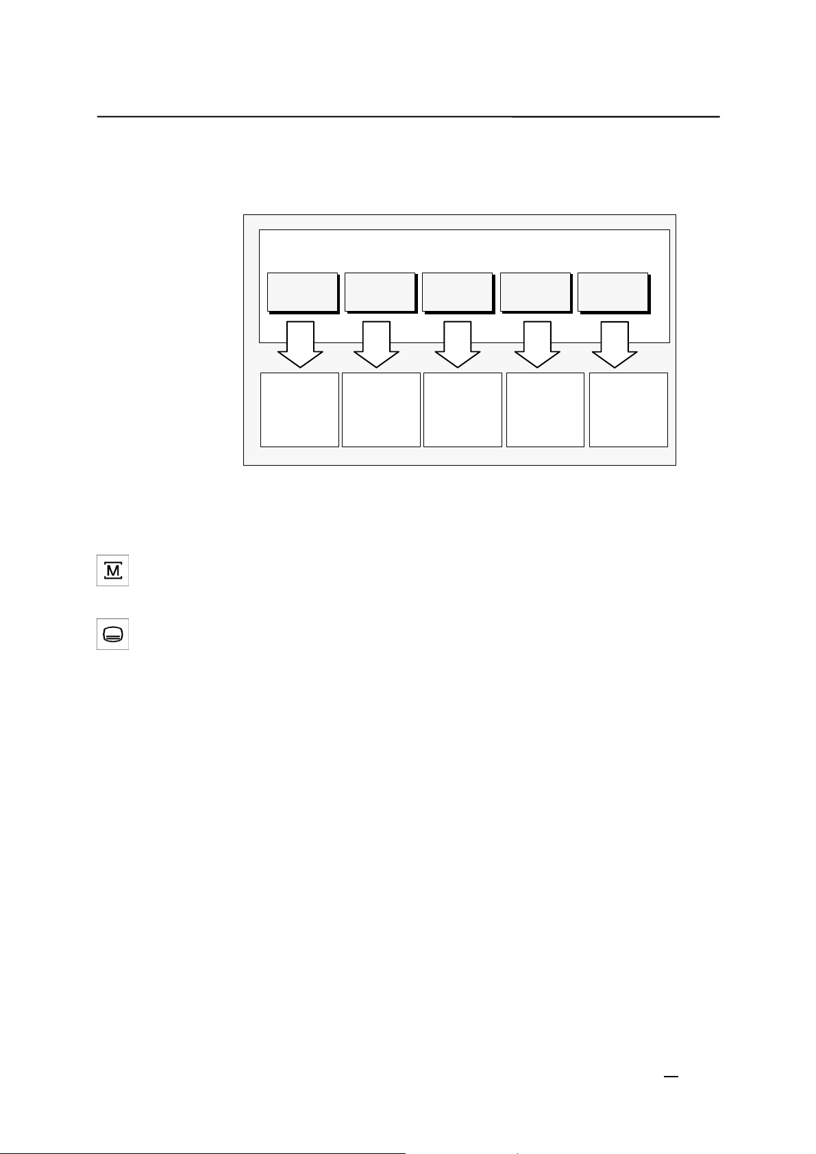
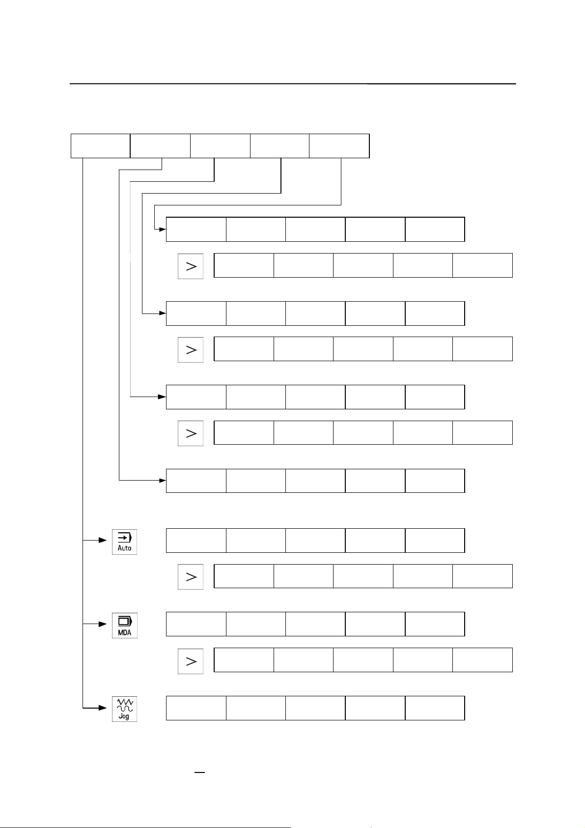
1.2 Operating areas
The basic functions are grouped in the CNC into the following operating areas:
Machine Parameter Program Services
Executing
part
programs
Manual
control
Editing
program data
Creating
part
programs
Data
import /
export
Diagnosis
Alarm display
Start-up
Fig.1-2 SINUMERIK 802S base line operating areas
Switching between
the operating areas
Press the “Machine area” key for direct access to the “Machine” operating
area.
Use the area switching key to return from any operating area to the main
menu.
Press the area switching key twice to return to the previous operating area.
After turning on the control system, you will always find yourself in the Machine
operating area.
Protection levels
Sensible points of the control system are password-protected against entering
and modifying data.
However, the operator can alter the classes of protection in the “Machine data
display” menu in the “Diagnosis” operating area.
Default: protection level 3.
In the following menus, entering and modifying data depends on the set
protection class:
tool offsets
z
zero offsets
z
setting data
z
RS232 setting
z
1-4
Operation and Programming
SINUMERIK 802S/C base line
Milling
Page 15
Introduction
1.3 Overview of the most important softkey functions
Machine Parameter Program Services Diagnosis
Alarms
Display
bright.
Data In
Start
Programs Cycles Selection Open
R
Parameter
Data Out
Start
New Copy Delete Rename
Tool
correction
Service
display
Display
darker
RS232
setting
Execut. f.
ext.
Setting
data
Start-up
Change
lang.
Error log show
Zero
offset
Machine
data
Memory
info
Program
control
Axis feed.
Axis feed.
Hand wheel Axis feed.
SINUMERIK 802S/C base line
Operation and Programming Milling
Zoom block Search
Execut.f.
ext.
Zoom block
Act.val
WC
Zoom G
funct
Act.val
WC
Zoom G
funct
Act.val
WC
Zoom
act.val
Zoom M
funct
Zoom
act.val
Zoom M
funct
Zoom
act.val.
1-5
Page 16
Introduction
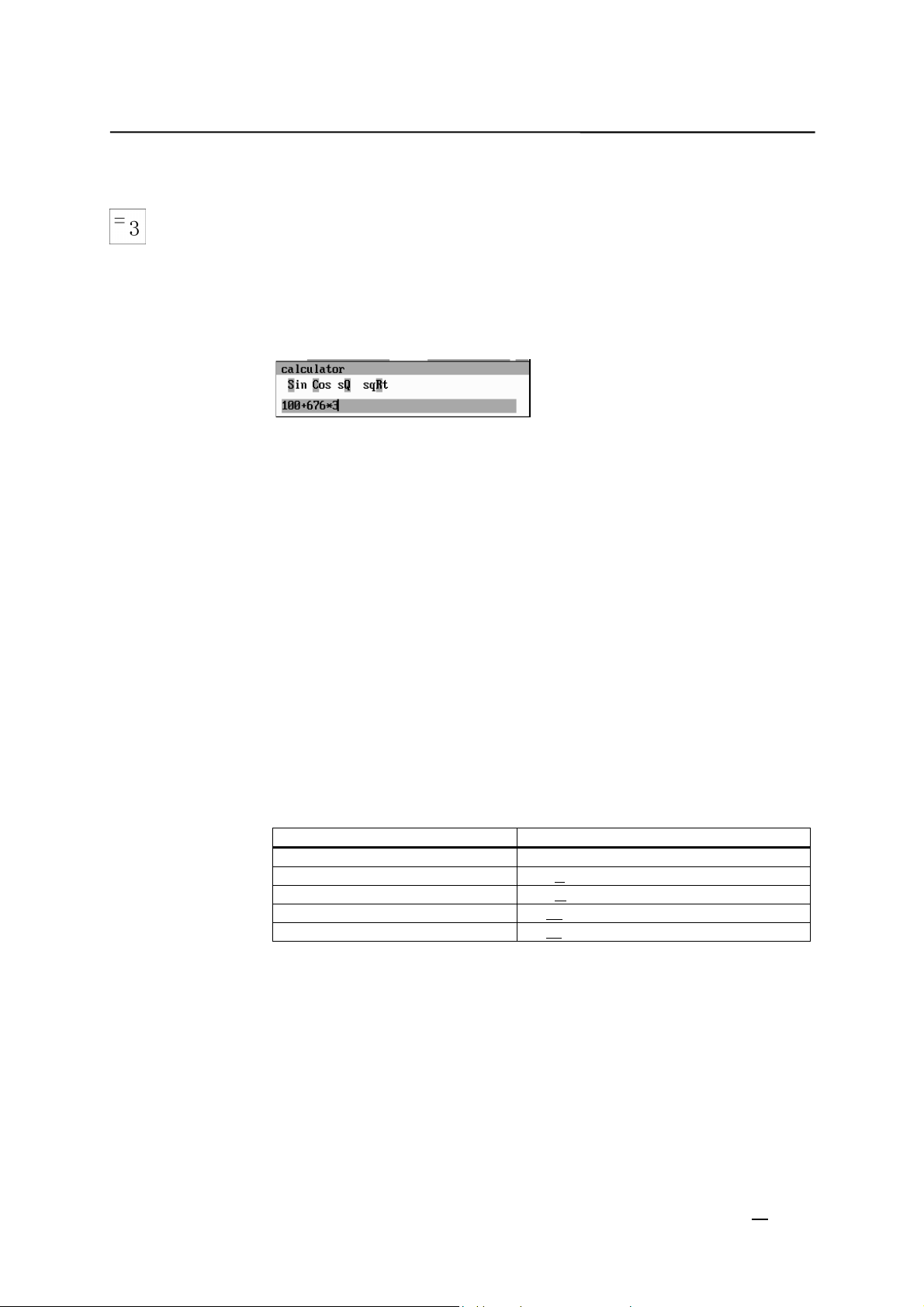
1.4 Pocket calculator
This function can be activated for all input fields intended for entry of numerical
values by means of the “=” character. To calculate the required value, you can
use the four basic arithmetic operations, and the functions sine, cosine,
squaring, as well as the square root function.
If the input field is already loaded with a value, this function writes the value in
the input line of the pocket calculator.
Fig.1-3 Pocket calculator
Permissible
character
+ Value X plus value Y
- Value X minus value Y
* Value X multiplied with value Y
/ Value X divided by value Y
S Sine function
C Cosine function
Q Square function
R Square root function
The following characters are permitted for input:
he value X in front of the input cursor is replaced by the value sin(X).
The value X in front of the input cursor is replaced by the value cos(X).
The value X in front of the input cursor is replaced by the value X
The value X in front of the input cursor is replaced by the value ¥;
2.
Calculation examples
Task Input
100 + (67*3) 100+67*3
sin(45_) 45 S -> 0.707107
cos(45_) 45 C -> 0.707107
2
4
4 Q -> 16
¥ 4 R -> 2
The calculation is carried out when the Input key is pressed. The function
writes the result to the input field and automatically closes the pocket
calculator.
To calculate auxiliary points on a contour, the pocket calculator provides the
following functions:
calculating the tangential transition between a circle sector and a straight
z
line
moving a point in a plane
z
converting polar coordinates into Cartesian coordinates
z
1-6
Operation and Programming
SINUMERIK 802S/C base line
Milling
Page 17
Introduction
adding the second end point of a contour section ‘straight line - straight
z
line’ given via angular interrelation.
These functions are directly linked with the input fields of the programming
support. Any values in this input field are written by the pocket calculator into
the input line, and the result is automatically copied into the input fields of the
programming support.
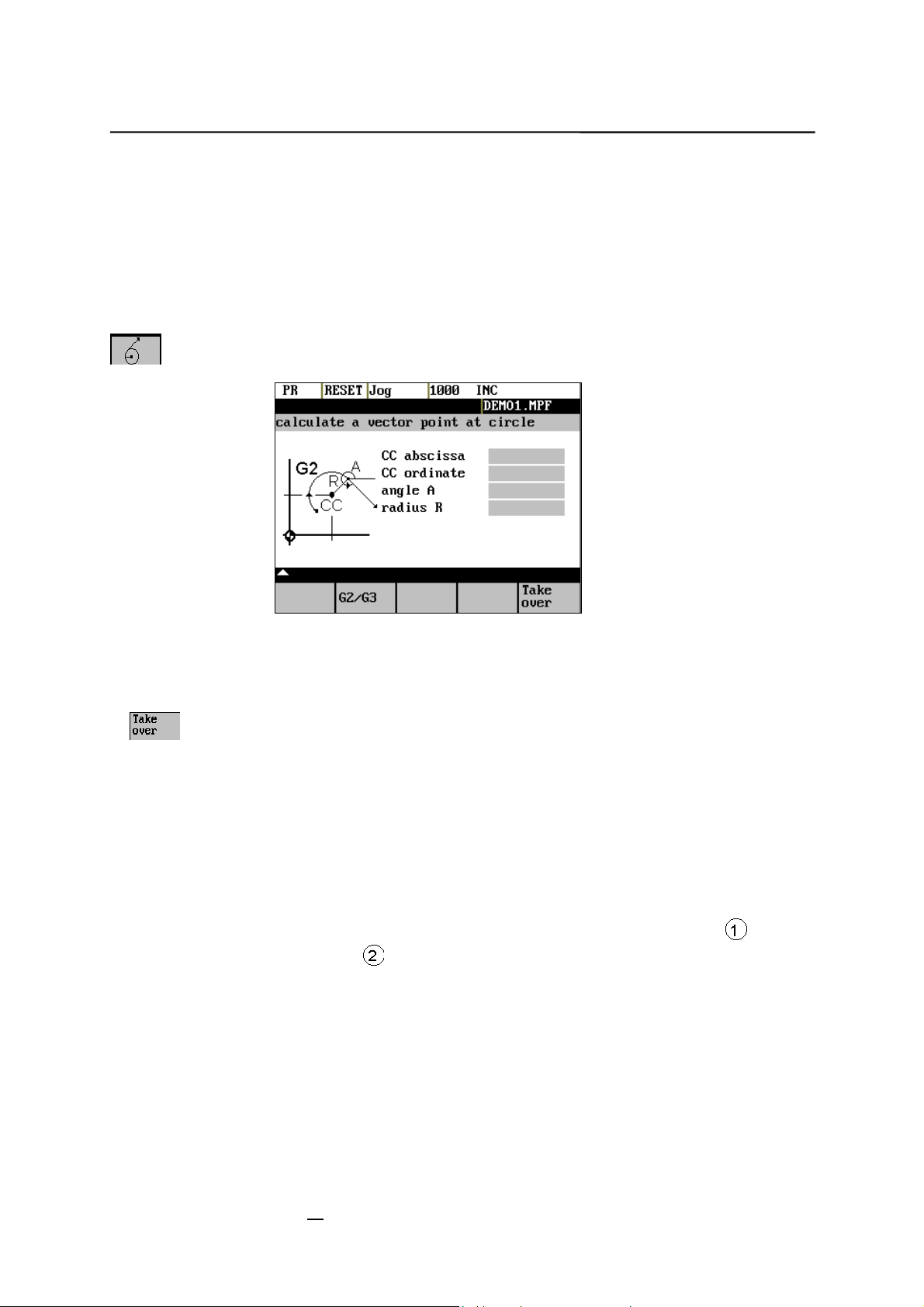
Softkeys
This function is used to calculate a point on a circle. The point results from the
angle of the created tangent and the direction of rotation of the circle.
Fig.1-4 calculation of a point on a circle
Enter the circle center, the angle of the tangent and the radius of the circle.
Use the softkeys G2 / G3 to define the direction of rotation of the circle.
The values of abscissa and ordinate are calculated. The abscissa is the first
axis of the plane, and the ordinate the second axis of the plane.
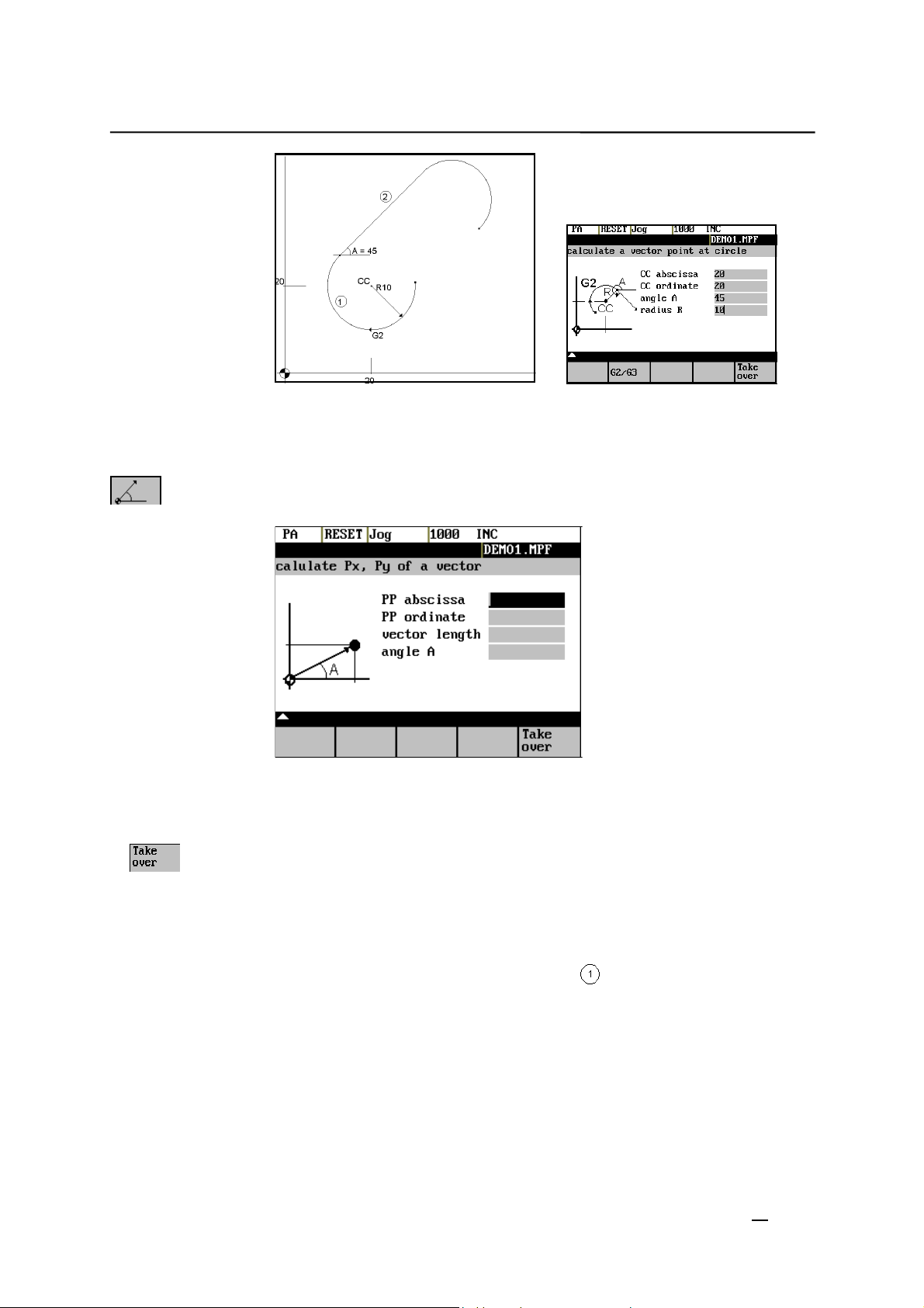
Example
If plane G17 is active, the abscissa is the X axis, and the ordinate the Y axis.
The value of the abscissa is copied into that input field from which the pocket
calculator function has been called, and the ordinate value into the next
following input field.
Example
Calculating the intersection point between the circle sector and the
straight line
.
Given: Radius: 10
Circle center point: X 20 Y20
Ongoing angle of the straight line: 45°
SINUMERIK 802S/C base line
Operation and Programming Milling
1-7
Page 18
Introduction
Result: X = 12.928
Y = 27.071
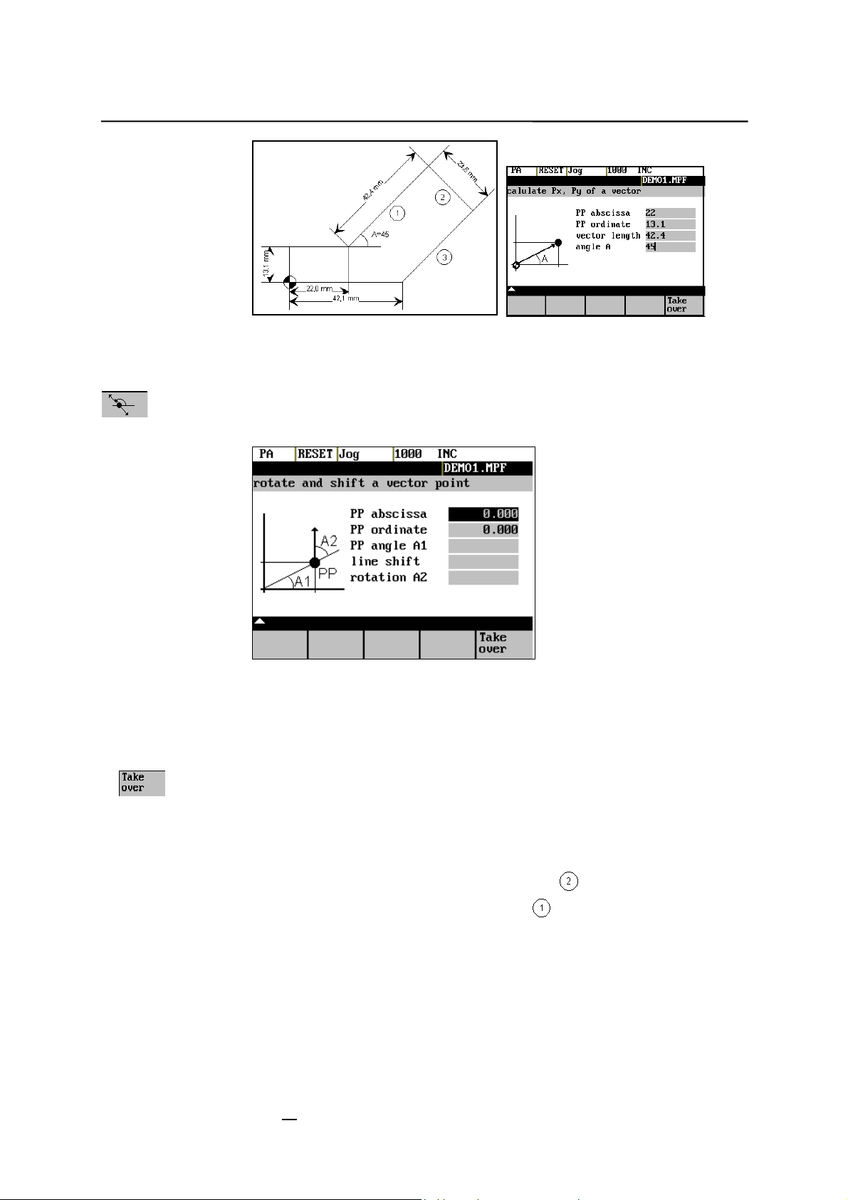
The function calculates the Cartesian coordinates from a straight line specified
by length and rise angle.
Fig.1-5 Conversion of the polar coordinates into Cartesian coordinates
Enter the pole point (PP) as both an abscissa and ordinate value, the length
and the rise angle of the straight line.
The values of abscissa and ordinate are calculated.
The abscissa value is copied into the input field from which the pocket
calculator function has been called, and the ordinate value into the next
following input field.
Example
1-8
Operation and Programming
Calculating the end point of the straight line . The straight line is defined by
the angle A=45° and its length..
SINUMERIK 802S/C base line
Milling
Page 19
Introduction
Result: X = 51.981
Y = 43.081
This function can be used to move a point in the plane. The point is on a
straight line defined by its rise angle.
Fig.1-6 Moving a point in the plane
Enter the rise angle of the straight line and the coordinates of the point.
Enter line shift and rotation of the point with refer to the straight line in the fields
“line shift” and “rotation”.
The values of abscissa and ordinate are calculated.
The pocket calculator copies the abscissa value into the input field from which
the pocket calculator function has been called, and the ordinate value into the
next following input field.
Example
Calculating the end point of the straight line . The straight line stands
vertical on the end point of the straight line
43.081). The length of the straight line is also given.
(coordinates: X = 51.981, Y =
SINUMERIK 802S/C base line
Operation and Programming Milling
1-9
Page 20
Introduction
Result: X = 68.668
Y = 26.393
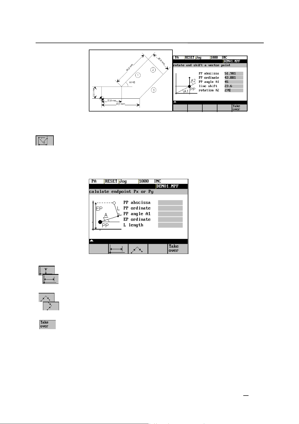
This function calculates the missing end point of the contour section straight
line - straight line, with the second straight line standing vertically on the first
straight line.
The following values of the straight line are known:
Straight line 1: Starting point and rise angle
Straight line 2: Length and one end point in the Cartesian coordinate system
Fig.1-7
This function chooses the given coordinate of the end position.
The value of ordinate and/or abscissa is given.
The second straight line is rotated in clockwise direction or, with refer to the
first straight line, rotated by 90 degrees in counter-clockwise direction. The
function chosses the appropriate setting.
The missing end position is calculated. The value of the abscissa is copied into
that input field from which the pocket calculator function has been called, and
the ordinate value into the next following input field.
1-10
SINUMERIK 802S/C base line
Operation and Programming
Milling
Page 21
Introduction
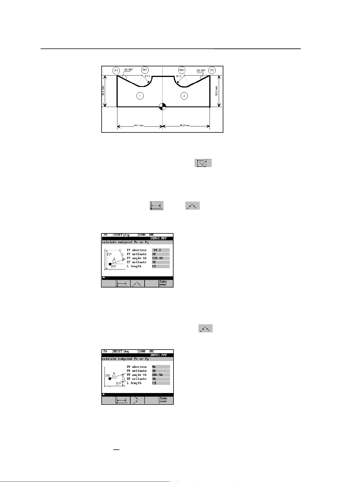
Example
The drawing above must be added by the values of the of the circle center
points to be able to calculate the intersection points between the contour
sections. Calculating the missing coordinates of the center points is carried out
with the pocket calculator function
transition stands vertical on the straight line.
Calculating M1 in section 1:
In this section, the radius stands on the straight line section in counter-
clockwise direction.
, since the radius in the tangential
Use the softkeys
Enter the coordinates, the pole point P1, the rise angle of the straight line, the
given ordinate value and the circle radius as the length.
Result: X = -19.449
Y = 30
Calculating M2 in section 2:
In this section, the radius stands on the straight line section rotated in
clockwise direction. Use the softkeys to select the given constellation.
Enter the parameters in the screen form.
and to select the given constellation.
Result X = 21.399
Y = 30
SINUMERIK 802S/C base line
Operation and Programming Milling
1-11
Page 22
Introduction
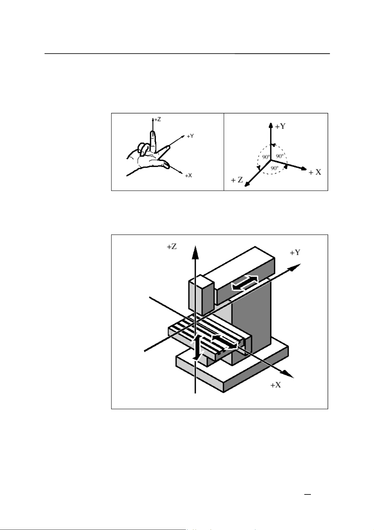
1.5 Basic principles
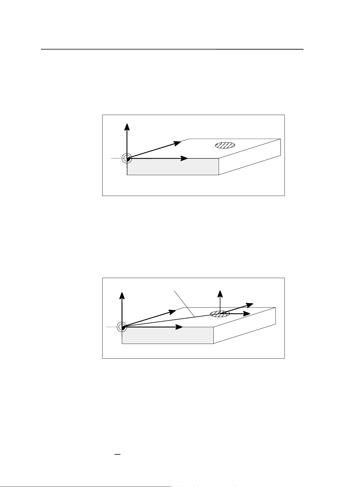
Coordinate system
Fig.1-8 Specification of mutual relationship between axis directions
Machine coordinate
system (MCS)
Right-handed, rectangular coordinate systems are used for machine tools.
Such systems describe the movements on the machine as a relative motion
between tool and workpiece.
The orientation of the coordinate system on the machine tool depends on the
particular machine type. It can be turned to various positions.
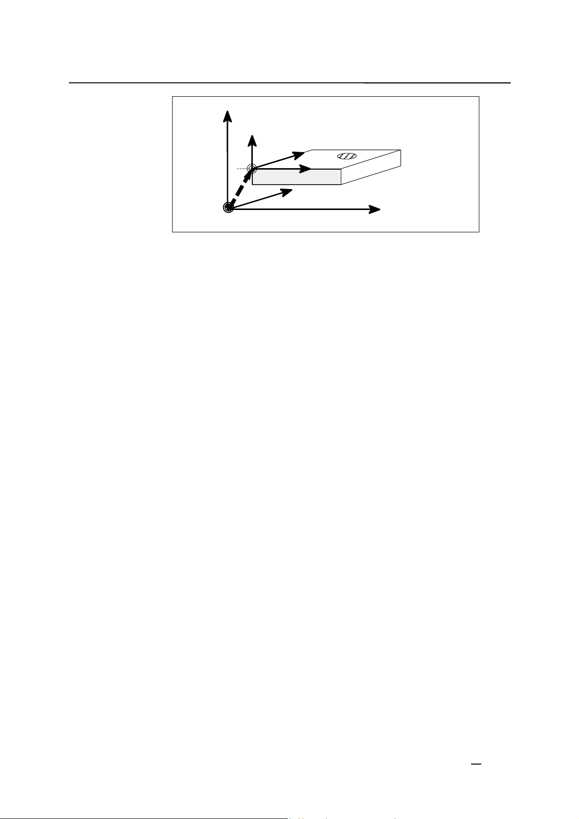
Fig.1-9 Example of machine coordinates/axes
The origin of the coordinate system is the machine zero.
All axes are in zero position at this point. This point is merely a reference point
determined by the machine manufacturer. It needs not to be approachable.
The traversing range of the machine axes can be negative.
1-12
Operation and Programming
SINUMERIK 802S/C base line
Milling
Page 23
Introduction
Workpiece coordInate system (WCS)
The definition of the directions is based on the assumption that the workpiece
The workpiece coordinate system described above (see Fi g. 1–8) is also used
to describe the geometry of a workpiece in the workpiece program.
The workpiece zero can be freely selected by the programmer. The programmer
need not know the real movement conditions on the machine, i.e. whether the
workpiece or the tool moves; this can be different in the individual axes.
does not move and the tool moves.
Z
Y
W
Fig.1-10 Workpiece coordinate system
Current workpiece
coordinate system
The use of the programmable zero offset provides a completely new current
from another zero than the initially selected zero (workpiece zero), he can
W= workpiece zero
If the programmer feels that it is better to continue his geometrical descriptions
define a new zero using the programmable zero offset. Reference is always
made to the original zero.
workpiece coordinate system. The current workpiece coordinate system can
also be turned to the original workpiece coordinate system (see Section
“Programmable Zero Offset and Rotation”).
X
Programmable offset G158
Z
W
Fig.1-11
Workpiece
clamping
SINUMERIK 802S/C base line
Operation and Programming Milling
be aligned such that the axes of the workpiece coordinate system run in
W= workpiece zero
To machine the workpiece, it is clamped on the m ach ine. Th e workpi ece must
parallel with the machine axes. Any resultant offset of the machine zero is
determined for each axis and entered into the intended data areas for the
settable zero offset. This offset is activated during the NC program execution
by means, for example, of a programmable G54 (see Section “Workpiece
Clamping - Settable Zero Offset ...”).
Y
X
Z
Current
Y
X
1-13
Page 24
Introduction
Z
Machine
Z
Workpiece
W=workpi ece zero
M=machine zero
Y
W
z.B.
G54
Fig.1-12 Workpiece on the machine
M
X
Y
Machine
X
Machine
1-14
SINUMERIK 802S/C base line
Operation and Programming
Milling
Page 25
Turning On and Reference
2
Point Approach
Note
Before you switch on the SINUMERIK and the machines, you should also have
read the machine documentation, since turning on and reference point
approach are machine-dependent functions.
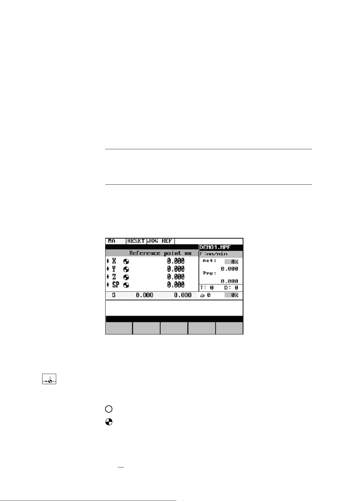
Operating sequence
First switch on the power supply of the CNC and of the machine. After the
control system has booted, you are in the “Machine” operating area, in the Jog
operating mode.
The Reference point approach window is active.
Fig.2-1 Jog Ref basic screen
Reference-point approach can only be executed in the Jog mode.
Activate the “Approach reference point” function by selecting the Ref key on
the machine control panel area.
In the “Reference point approach” window (Fig. 2–1), it is displayed whether or
not the axes have to be referenced.
Axis has to be referenced
SINUMERIK 802S/C base line
Operation and Programming
Axis has reached the reference point
Milling
2-1
Page 26

Turning On and Reference Point Approach
Press the direction keys.
The axis does not move if you select the wrong direction.
Approach the reference point in each axis successively.
You can quit the function by selecting another operating mode (MDA,
Automatic or Jog).
2-2
SINUMERIK 802S/C base line
Operation and Programming
Milling
Page 27
Setup
3
Preliminary remarks
Before you can use the CNC, set up the machine, tools, etc. on the CNC by:
entering the tools and tool offsets
z
entering/modifying the zero offset
z
entering the setting data
z
3.1 Entering tools and tool offsets
Functionality
Each tool has a defined number of parameters depending on the tool type.
Each tool is identified by its own tool number (T number).
See also Section 8.6 “Tool and Tool Offset”.
Operating sequences
Parameter
Tool
Corr.
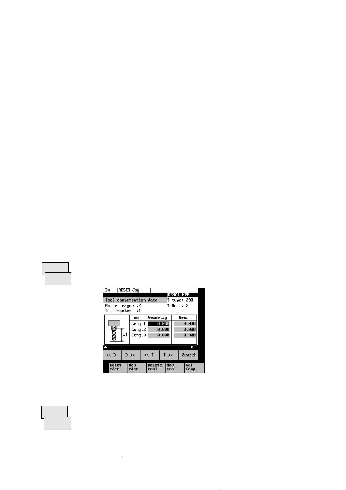
The tool offsets consist of several data that describe the geometry, wear and
tool type.
This function opens the
offset values of the currently active tool. If you select another tool using the
or
softkeys, the setting remains when you quit the window.
T>>
Tool Compensation Data
window, which contains the
<<T
Fig.3-1 Tool list
Softkeys
<< D
D >>
SINUMERIK 802S/C base line
Operation and Programming Milling
Select next lower or next higher edge number.
3-1
Page 28

Setup
<< T
T >>
Search
Pressing this softkey opens the dialog box and the overview of the tool
numbers assigned. Enter the tool number you search for in the input window
and start search with OK. If the searched tool exists, the search function opens
the tool offset data box.
Press the ETC key to extend the softkey functions.
Select next lower or next higher tool.
Reset
edge
New
edge
The new edge is created for the currently displayed tool; it is automatically
All edge compensation values are reset to zero.
Creates a new edge and loads it with the appropriate parameters.
assigned the next higher edge number (D1 – D9).
Max. 30 edges (in total) can be stored in the memory.
Delete
tool
Deletes the tool compensation data of all edges of the selected tool.
New
Creates new tool compensation data for a new tool.
tool
Get
Comp.
Note: Max. 20 tools can be created.
Determines the length compensation values.
3-2
SINUMERIK 802S/C base line
Operation and Programming
Milling
Page 29
Setup
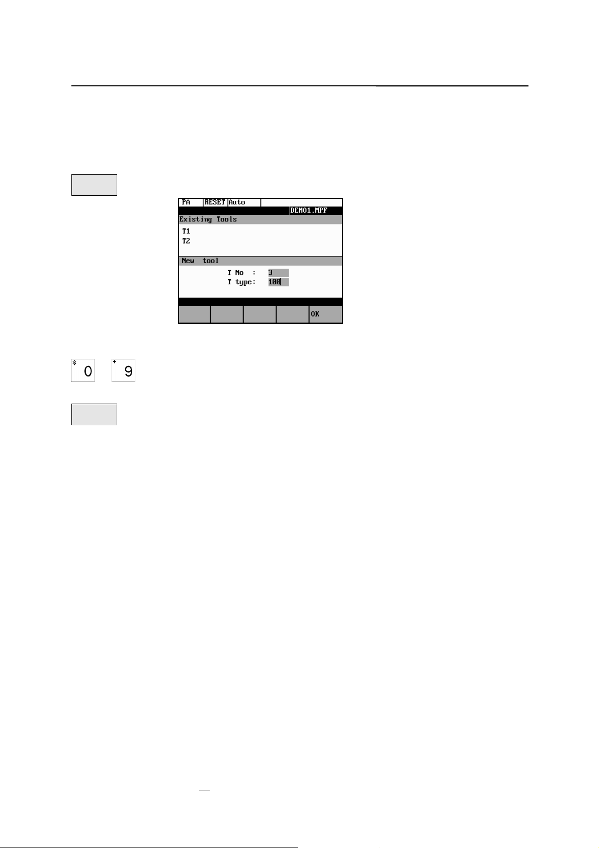
3.1.1 Creating a new tool
Operating sequence
Press this softkey to create a new tool.
Pressing this softkey opens the input window and an overview of the tool
New
tool
Fig.3-2 New Tool window
numbers assigned.
… Enter the new T number (maximal only three digits) and specify the tool type.
Press OK to confirm your entry; the Tool Compensation Data window is
OK
opened.
SINUMERIK 802S/C base line
Operation and Programming Milling
3-3
Page 30
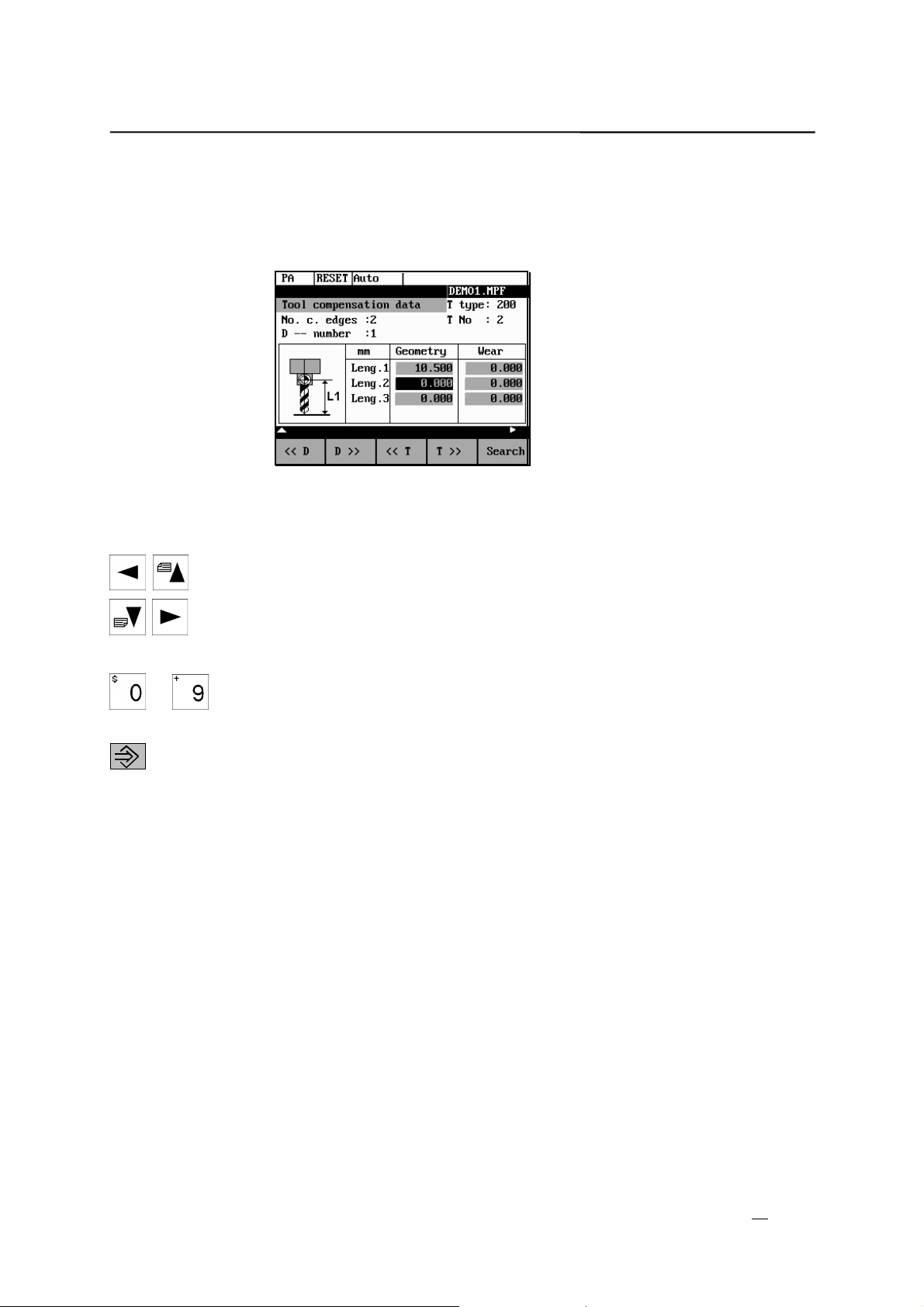
Setup
3.1.2 Tool compensation data
The tool compensation data are divided into length and radius compensation
data.
The list is structured according to the tool type.
Fig. 3-3 Tool compensation d ata
Operating sequence
positioning the cursor on the input field to be modified,
… entering value(s)
Enter the offsets by
and confirming your entry by pressing Input or a cursor selection.
3-4
SINUMERIK 802S/C base line
Operation and Programming
Milling
Page 31

Setup
3.1.3 Determining the tool offsets
Functionality
Prerequisite
This function can be used to determine the unknown geometry of a tool T.
The appropriate tool has been changed. In JOG mode, approach a point on the
machine, from which you know the machine coordinates, with the edge of the
tool. This can be a workpiece with a known position. The machine coordinate
value can be split into two components: stored zero offset and offset.
Procedure
Enter the offset value in the intended Offset field. Then select the required zero
offset (e.g. G54) or G500 if no zero offset is to be calculated. These entries
must be made for each selected axis (see Fig. 3-5).
Please note the following: For milling tools, length 1 and the radius must be
determined, and for drilling tools only length 1.
Using the actual position of point F (machine coordinate), the offset entry and
the selected zero offset Gxx (position of the edge), the control system can
calculate the assigned compensation value of length 1 or the tool radius.
Note:
You can also use a zero offset already determined (e.g. G54 value) as
the known machine coordinate. In this case, approach the workpiece zero with
the edge of the tool. If the edge stands directly at the workpiece zero, the offset
value is zero.
F-tool carrier reference point
M-machine zero
W-workpiece zero
Z
Machine
Workpiece
Interm. layer
W
F
Length 1=?
Actual position Z
Known machine
coordinate value Z
Offset
M
Gxx, z.B. G54
X
Machine
Fig.3-4 Determination of length compensation using the example of a drill:
length 1/Z axis
SINUMERIK 802S/C base line
3-5
Operation and Programming Milling
Page 32

Setup
Operating sequence
Get
Comp.
Select the softkey Get Comp. The window Compensation values opens.
Fig.3-5 Window compensation values
Enter offset if the tool edge cannot approach the zero point Gxx. If you
z
work without zero offset, select G500 and and enter offset.
When the softkey Calculate is pressed, the control system determines the
z
searched geometry length 1 or the radius depending on the preselected
axis. This geometry is calculated on the basis of the approached actual
position, the selected Gxx function and the entered offset value.
The determined compensation value is stored.
3-6
SINUMERIK 802S/C base line
Operation and Programming
Milling
Page 33

Setup
3.2 Entering/modifying zero offsets
Functionality
The actual-value memory and thus also the actual-value display are referred to
the machine zero after the reference-point approach. The workpiece machining
program, however, refers to the workpiece zero.
This offset must be entered as the zero offset.
Operating sequence
Parameter
An overview of settable zero offsets appears on the screen .
Zero
offset
Use the Parameter and Zero Offset softkeys to select the zero offset.
Fig.3-6 Zero offset window
Position the cursor bar on the input field to be altered,
… enter value(s).
The next zero offset overview is displayed by Page down together with shift
key. G56 and G57 are now displayed.
Return to next-higher menu level, without saving the zero offset values.
Softkeys
Determine
Use this function to determine the zero offset with refer to the coordinate origin
of the machine coordinate system. When you have selected the tool, which you
want to use for measuring, you can set the appropriate conditions in the
Determine
window.
SINUMERIK 802S/C base line
Operation and Programming Milling
3-7
Page 34
Setup
Fig.3-7 Zero offset measuring using the Determine function
The toggle fields can be used to calculate the tool compensation values.
It is possible to specify an additional length in the Offset box, which must then
be considered in the calculation (for example, when using a spacer).
The current axis position, the active compensation value and the tool
compensation data are displayed.
Move the tool to the selected zero and set all compensation values for the
selected axis. The Calculate softkey function will then caluclate the offset and
enter the value in the respective field. This process must be repeated for all
axes.
Next
Uframe
Next
Axis
Calculate
OK
Pro–
grammed
Sum
Selects the next settable zero offset.
Selects the next axis.
The compensation values are caluclated with the Offset field and the current
axis position (MCS). The result will be assigned to the selected axis as an
offset value.
Closes the window.
Opens a window with the programmed zero offset. The value shown in the
window cannot be edited.
Displays the total of all active zero offsets. The values cannot be edited.
3-8
SINUMERIK 802S/C base line
Operation and Programming
Milling
Page 35

Setup
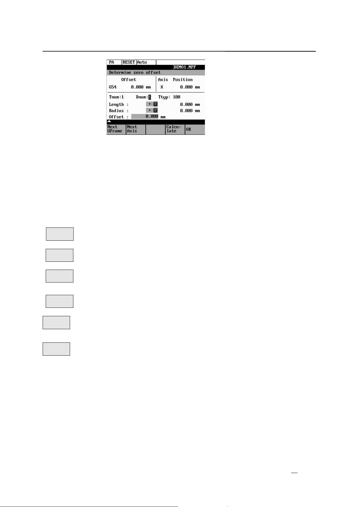
3.2.1 Determining the zero offset
Prerequisite
You have selected the window with the corresponding zero offset (e.g. G54)
and the axis for which you want to determine the offset.
Fig.3-8 Determining the zero offset for the Z axis
Approach
A zero offset can only be determined with a known (entered geometry)
z
and active tool. Enter the active tool in the dialog box. Press OK to take
over the tool; the Determine window is then opened.
The selected axis appears in the Axis area.
z
The actual position of the tool support reference point (MCS) associated
to the axis is displayed in the adjacent field.
D number 1 is displayed for the tool edge.
z
If you have entered the valid offsets for the used tool under a D number
other than D1, enter that D number here.
The stored tool type is displayed automatically.
z
The effective length compensation value (geometry) is displayed.
z
Select the sign (-, +) for calculating the length offset, or select “without”
z
taking the length offset into account.
A negative sign subtracts the length offset value from the actual position.
If the tool can neither reach, nor “scrape” the desired position, an offset
z
value can be entered in the Offset field.
Approach the coordinates of the intended workpiece zero offset (if
z
necessary with consideration of the entered offset value) in JOG mode.
The resulting zero offset is determined from the actual position and all
z
active compensation values by means of the Calculate function.
SINUMERIK 802S/C base line
Operation and Programming Milling
3-9
Page 36

Setup
Fig.3-9 Select tool screen form
Fig.3-10 Determine zero offset form
Next
UFrame
Calculate
Press the OK softkey to quit the window.
OK
Softkey can be used to select the zero offsets G54 to G57. The selected zero
offset is displayed on the selected softkey.
Pressing the Calculate softkey calculates the zero offset.
3-10
SINUMERIK 802S/C base line
Operation and Programming
Milling
Page 37

Setup
3.3 Programming the setting data - “Parameters” operating area
Functionality
Use the setting data to define the settings for the operating states. These can
also be modified if necessary.
Operating sequence
Use the Parameter and Setting Data softkeys to select Setting Data.
Parameter
The Setting Data softkey branches to another menu level in which various
Sett.
data
control options can be set.
Fig.3-11 Setting data basic screen
Use the paging keys to position the cursor on the desired line within the display
areas.
… Enter the new value in the input fields.
Use Input or the cursor keys to confirm.
Softkeys
Jog
data
Jog feed
This function can be used to change the following settings:
Feed value in Jog mode
If the feed value is zero, the control system uses the value stored in the
machine data.
Spindle
Spindle speed
Direction of rotation of the spindle
SINUMERIK 802S/C base line
Operation and Programming Milling
3-11
Page 38

Setup
Spindle
data
Limits for the spindle speed set in the Max. (G26)/Min. (G25) fields must be
Minimum / Maximum
within the limit values specified in the machine data.
Programmed (LIMS)
Programmable upper speed limitation (LIMS) at constant cutting speed (G96).
Dry
feed
The feedrate you enter here is used in the program execution instead of the
Dry-run feedrate for dry-run operation (DRY)
programmed feed during the Automatic mode when the Dry-Run Feedrate is
active (see Program Control, Fig. 5–3).
Start
angle
A start angle representing the starting position for the spindle is displayed for
Start angle for thread cutting (SF)
thread cutting operations. It is possible to cut a multiple thread by altering the
angle and repeating the thread cutting operation.
3-12
SINUMERIK 802S/C base line
Operation and Programming
Milling
Page 39

Setup
3.4 R parameters – “Parameters” operating area
Functionality
All R parameters (arithmetic parameters) that exist in the control system are
displayed on the R Parameters mainscreen as a list (see also Section 8.8
“Arithmetic Parameters /R Parameters/”).
These can be modified if necessary.
Fig.3-12 R parameters window
Operating sequence
Parameters
R Parameters
Use the Parameter and R Parameter softkeys
to position the cursor on the input field that you want to edit.
Enter value(s).
Press Input or use the cursor keys to confirm.
SINUMERIK 802S/C base line
Operation and Programming Milling
3-13
Page 40

Setup
3-14
SINUMERIK 802S/C base line
Operation and Programming
Milling
Page 41

Manually Operated Mode
4
Preliminary remarks
In the Jog mode, you can traverse the axes, and in the MDA mode, you can
The manually operated mode is possible in the Jog and MDA mode.
enter and execute individual part program blocks.
4.1 Jog mode – “Machine” operating area
Functionality
Operating sequence
...
As long as the direction key is pressed and hold down, the axes traverse
In the Jog mode, you can
traverse the axes and
z
set the traversing speed by means of the override switch, etc.
z
Use the Jog key in the machine control panel area to select the Jog mode.
To traverse the axes, press the appropriate axis direction keys.
continuously at the speed stored in the setting data. If this setting is zero, the
value stored in the machine data is used.
… If necessary use the override button key to set the traversing speed.
It can be adjusted by settable increments:
0%, 1%, 2%, 4%, 8%, 10%, 20%, 30%, 40%, 50%, 60%, 75%, 80%, 85%, 90%,
95%, 100%, 105%, 110%, 115%, 120%.
If you press the Rapid Traverse Override key at the same time, the selected
axis is traversed at rapid traverse speed for as long as both keys are pressed
down.
In the Incremental Feed operating mode, you can use the same operating
sequence to traverse the axis by settable increments. The set increment is
displayed in the display area. Jog must be pressed again to cancel the
Increment Feed.
SINUMERIK 802S/C base line
Operation and Programming Milling
4-1
Page 42
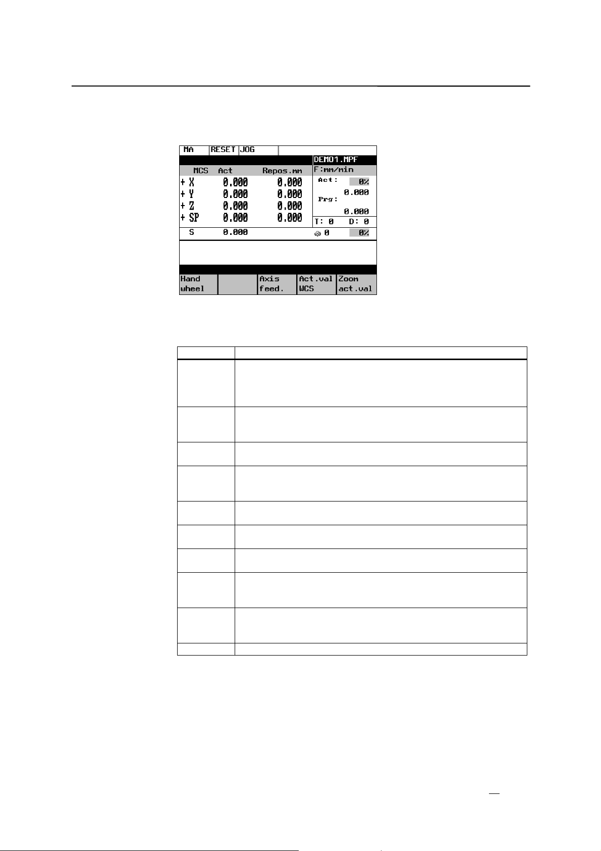
Manually Operated Mode
The Jog basic screen displays position, feed and spindle values including the
feedrate override and spindle override, gear stage status as well as the current
tool.
Fig.4-1 Jog basic screen
Parameters
Table 4–1 Description of parameters in the Jog basic screen
Parameter Explanation
MKS
X
Y
Z
+X– Z If you traverse an axis in the positive (+) or negative (–)
Act.
mm
Repos
offset
Spindle S
rpm
Feed F
mm/min
Tool Display of currently active tool with the current cutting edge
Actual
feedrate
override
Actual
spindle
override
Gear stage Display of current gear stage in the machine
Display of addresses of existing axes in machine coordinate
system (MCS).
direction, a plus or minus sign appears in the respective field.
No axis is displayed, if the axis is in position.
The current position of the axes in the MCS or WCS is displayed
in these fields.
If the axes are traversed in the Jog mode in the Program
Interrupted condition, the distance traversed by each axis in
relation to the break point is displayed in this column.
Display of actual value and setpoint of spindle speed
Display of path feed actual value and setpoint
number
Display of current feedrate override
Display of current spindlel speed override
4-2
SINUMERIK 802S/C base line
Operation and Programming
Milling
Page 43
Manually Operated Mode
Softkeys
Handwheel
Call the Handwheel window .
Call the Axis Feed or Interp. Feed window .
Axis
Use this softkey to change between the Axis Feed window and the Interp. Feed
feed
Interp./
The softkey label changes to Interp. feed when the Axis/Feed window is
feed
window.
opened.
Act. val.
WCS
Act.val.
MCS
The softkey changes between MCS and WCS. When doing this, the softkey
The actual values are displayed as a function of the selected coordinate
system. There are two different coordinate systems, i.e. the machine
coordinate system (MCS) and the workpiece coordinate sy stem (WCS).
label changes as follows:
The values of the machine coordinate system are selected, the softkey
z
label changes to Act. val. WCS.
When the workpiece coordinate system is selected, the label changes to
z
Act. val. MCS.
Zoom
act.val.
Enlarged view of actual values
Pressing Recall key , return to the next-higher menu level.
SINUMERIK 802S/C base line
Operation and Programming Milling
4-3
Page 44

Manually Operated Mode
4.1.1 Assigning handwheels
An axis is assigned to the respective handwheel and becomes active as soon
as you press OK.
Operating sequence
Hand–
wheel
After the window has opened, all axis identifiers are displayed in the Axis
In Jog mode, call the Handwheel window.
column and also appear in the softkey bar. Depending on the number of
connected handwheels, it is possible to change from handwheel 1 to
handwheel 2 using the cursor.
Place the cursor on the line with the handwheel to which you wish to assign an
axis. Then select the softkey that contains the name of the axis.
The symbol
appears in the window.
Fig.4-2 Handwheel window
WCS
MCS
The WCS/MCS softkey is used to select the axes from the machine or
workpiece coordinate system for assignment to the handwheel. The current
setting is displayed in the handwheel window.
OK
Use the OK softkey to take over the selected setting; the window is then closed.
Menu extension
Deselect
4-4
The assignment you have made is reset for the selected handwheel.
SINUMERIK 802S/C base line
Operation and Programming
Milling
Page 45

Manually Operated Mode
4.2 MDA Mode (Manual Data Input) – “Machine” operating area
Functionality
Contours that require several blocks (e.g. roundings, chamfers) cannot be
Caution
This mode is protected by the same safety interlocks as fully automatic mode.
!
Furthermore, the MDA mode is subject to the same prerequisites as the fully
Before NC-start of an input NC-program in the mode MDA is to wait till the
You can create and execute a part program block in the MDA mode.
executed/programmed.
automatic mode.
message “Block store active” displays on the screen.
Operating sequence
Use the MDA key in the machine control panel area to select the MDA mode.
Fig.4-3 MDA basic screen
Enter a block using the control keyboard.
The entered block is executed by pressing NC START. The block cannot be
executed while machining is taking place.
After processing, the contents of the input field remains stored so that the block
can be traversed with new NC Start. The block is deleted by entering any new
character.
SINUMERIK 802S/C base line
4-5
Operation and Programming Milling
Page 46

Manually Operated Mode
Parameters
Table 4–2 Description of the parameters in the MDA working window.
Parameter Explanation
MCS
Display of existing axes in MCS or WCS
X
Y
Z
+X
– Z
If you traverse an axis in the positive (+) or negative (–)
direction, a plus or minus sign appears in the respective field.
No sign is displayed if the axis is in position.
Act. valuemmThe current position of the axes in the MCS or WCS is displayed
in these fields.
Spindle S
Display of actual value and setpoint of spindle speed
rpm
Feed F Display of path feed actual value and setpoint in mm/min or
mm/rev.
Tool Display of currently active tool with the current tool edge number
(T..., D...).
Edit
window
Actual
In the Stop or Reset program state, an edit window is provided
for input of the part program block.
Display of current feedrate override
feedrate
override
Actual
Display of current spindlel speed override
spindle
override
Gear stage Display of current gear stage in the machine
Softkeys
Zoom
block
Act.val.
WCS
Act.val.
MCS
Zoom
act.val.
Axis
feed
Interp.
feed
Zoom
G funct.
The window shows the currently edited block full length.
The actual values for the MDA mode are displayed as a function of the
selected coordinate system.
There are two different coordinate systems, i.e. the machine coordinate sy stem
(MCS) and the workpiece coordinate system (WCS).
Enlarged view of the actual values
Menu extension
Display of Axis Feed or Interp. Feed window
This softkey can be used to change between the two windows. The softkey
label changes to Interp. Feed when the Axis Feed window is opened.
The G Function window contains all active G functions. Each G function is
assigned to a group and has a fixed position in the window.
More G functions can be displayed by pressing the PAGE UP or PAGE DOWN
keys together with Shift key. You can exit the window by pressing Recall.
Zoom
M funct.
4-6
Opens the M function window for displaying all active M functions of the block.
SINUMERIK 802S/C base line
Operation and Programming
Milling
Page 47

Automatic Mode
5
Functionality
Preconditions
Operating sequence
The Automatic basic screen appears that displays the position, feed, spindle,
In the Automatic mode, part programs can be executed fully automatically, i.e.
this is the operating mode for standard processing of part programs.
The preconditions for executing part programs are:
Reference point approached.
z
You have already stored the required part program in the control system.
z
You have checked or entered the necessary offset values, e.g. zero
z
offsets or tool offsets.
The required safety interlocks are activated.
z
Use the Automatic key to select the Automatic mode.
override and tool values, the gear stage status as well as the current block.
Fig.5-1 Automatic basic screen
SINUMERIK 802S/C base line
Operation and Programming Milling
5-1
Page 48
Automatic mode
Parameters
Table 5–1 Description of the parameters in the working window
Parameter Explanation
MCS
Display of existing axes in MCS or WCS.
X
Y
Z
+ X
– Z
If you traverse an axis in the positive (+) or negative (–)
direction, a plus or minus sign appears in the respective field.
No sign is displayed if the axis is in position.
Act. val.
mm
Distance
to go
Spindle S
The current position of the axes in the MCS or WCS is displayed
in these fields.
The remaining distance to be traversed by these axes in the
MCS or WCS is displayed in these fields.
Display of actual value and setpoint of spindle speed
rpm
Feed F
Display of path feed actual value and setpoint
mm/min or
mm/rev
Tool Display of currently active tool with the current cutting edge
number (T..., D...).
Current
block
Actual
The block display contains the current block. The block is output
in one line only and truncated if necessary.
Display of current feedrate override
feedrate
override
Actual
Display of current spindlel speed override
spindle
override
Gear stage Display of current gear stage in the machine
Softkeys
Progr.
control
Zoom
block
Search
Search
Interr.
point
Contin.
search
Start B
search
The window to select Program Control (e.g. skip block, program test) appears
on the screen.
This window displays the previous, current and next block in full. In addition,
the names of the current program or subroutine are displayed.
Use the Block Search function to jump to the desired point in the program.
The Search softkey provides the functions “Find line” and “Find text”.
The cursor is positioned to the main program block of the breakpoint (“interrupt
point”). The search target is automatically set in the subroutine levels.
Continue search
The Start B Search softkey starts the search process in which the same
calculations are carried out as in normal program mode, but without axis
movements.
The block search can be canceled by NC Reset.
5-2
SINUMERIK 802S/C base line
Operation and Programming
Milling
Page 49

O
Automatic mode
Act.val.
WCS
Act.val.
MCS
Zoom
act.val.
The values of the machine or workpiece coordinate system are selected. The
softkey label changes to Act. val. WCS or Act. val. MCS.
Enlarged view of actual values
Menu extension
Axis
feed
This softkey can be used to change between the windows. The softkey label
Interp.
feed
Execut
f. ext.
Zoom
G Funkt.
The G Function window contains all active G functions. Each G function is
When pressing these softkeys, the Axis Feed or Interp. Feed window appears.
changes to Interp. feed when the Axis Feed window is opened.
An external program is transferred to the control system via the RS232
interface and executed immediately by pressing NC Start.
Opens the
G Function
window to display all active G functions.
assigned to a group and has a fixed position in the window. More G functions
can be displayed by pressing the PAGE UP or PAGE DOWN keys together
with Shift key.
Fig.5-2 Active G functions window
Zoom
M funct.
Opens the M Function window to display all active M functions.
DEM
SINUMERIK 802S/C base line
Operation and Programming Milling
5-3
Page 50

Automatic mode
5.1 Selecting/starting a part program – “Machine” operating area
Functionality
The control system and the machine must be set up before the program is
started. Please note the safety instructions provided by the machine
manufacturer.
Operating sequence
Use the Automatic key to select the Automatic mode.
Program
Programs
An overview of all programs stored in the control system is displayed.
Position the cursor bar on the desired program.
Select
Progr.
control
The following program control functions can be activated and deactivated:
Use the Select softkey to select the desired program for processing.
If necessary now you can make settings for program control.
Fig.5-3 Program control window
The part program is executed when NC START is pressed.
5-4
SINUMERIK 802S/C base line
Operation and Programming
Milling
Page 51

M
5.2 Block search – “Machine” operating area
Automatic mode
Operating sequence
Precondition: The desired program has already been selected (cf. Section 5.1),
and the control system is in the reset state.
Search
The block search function can be used to advance the program up to the
desired point in the part program. The search target is set by positioning the
cursor directly on the desired block in the part program.
Fig.5-4 Block search window
Start B
search
The funktion starts program advance and closes the Search window.
Search result
The desired block is displayed in the Current Block window.
DEMO.
SINUMERIK 802S/C base line
Operation and Programming Milling
5-5
Page 52

Automatic mode
5.3 Stopping/cancelling a part program – “Machine” operating area
Functionality
Operating sequence
Part programs can be stopped and aborted.
The execution of a part program can be interrupted by selecting NC STOP.
The interrupted program can be continued by NC START .
The current program can be aborted by pressing RESET.
When you press NC START again, the aborted program is restarted and
executed from the beginning.
5-6
Operation and Programming
SINUMERIK 802S/C base line
Milling
Page 53

5.4 Repositioning after interruption
Automatic mode
Functionality
Operating sequence
Search
Interr.
point
Start B
search
After a program interruption (NC STOP), you can move the tool away from the
contour in the manual mode (Jog). The control system stores the coordinates
of the breakpoint (“interrupt point”). The path differences traversed by the axes
are displayed.
Select the Automatic mode.
Open the Block Search window to load the breakpoint.
The breakpoint is loaded. The routine is adjusted to the start position of the
interrupted block.
A block search to the breakpoint is started.
Continue execution of the program by NC START.
SINUMERIK 802S/C base line
Operation and Programming Milling
5-7
Page 54

Automatic mode
5.5 Program execution from external (RS232 interface)
Functionality
An external program is transferred into the control system via the RS232
interface and executed immediatelyby pressing NC Start.
While processing the contents of the buffer memory, the program is
automatically reloaded. For example, as an external device, a PC can be used,
on which the WinPCIN tool for data transfer is installed.
Operating sequence
Prerequisite: The control system is reset.
The RS232 interface is parameterized correctly (see Chapter 7) and not
occupied by any other application (DataIn, DatatOut, STEP7).
Execute
f. ext.
Use WinPCIN on the external device (PC) to set the program for data output
Press this softkey.
active.
The program is transferred to the buffer memory and automatically selected
and displayed in the program selection.
For the program execution, it is advantageous to wait until the buffer memory is
filled.
The program execution starts with NC START. The program is reloaded
continuously.
Either at the end of the program or when pressing RESET, the program is
automatically removed from the control system.
Note
As an alternative, External Program Execution can also be activated in
z
the Services area.
Any transfer errors are displayed in the Services area when you press the
z
Error log softkey.
5-8
SINUMERIK 802S/C base line
Operation and Programming
Milling
Page 55

5.6 Teach In
Automatic mode
Functionality
Use the submode Teach In to accept the axis position values directly into a
parts program block to be generated or modified.
The axis positions are approached either in Automatic mode by traversing the
JOG keys or by using the handwheel. However, first press the appropriate
softkey (see below) in the Programming operating area to enable the submode
Teach In.
Operating sequence
Prerequisite:
Teach-in o ption is set;
The control system is either in the state Stop or Reset.
A list of all programs existing in the control system is displayed.
Programs
open
Pressing Open calls the editor for the selected program and opens the editor
window.
Menu extension
Edit
Select
Menu extension
Teach In
Select
on
Fig.5-5 Teach In basic screen
Softkeys
Technol.
Data
Use this screen form to enter
Use this softkey to generate a block with technological data.
feed value
z
spindle speed and direction of rotation (CW; CCW; stop)
z
tool and edge number
z
SINUMERIK 802S/C base line
Operation and Programming Milling
5-9
Page 56

Automatic mode
machining level
z
Feed mode (active; mm/min corresponds to G64; mm/rev. of spindle
z
corresponds to G96)
Positioning behavior (active; exact stop G60; continuous-path control
z
mode G64)
Fig.5-6 Input screen form for technological data
When you press OK, a block with the technological data entered is generated
and inserted in front of the block to which the cursor is positioned. Pressing
RECALL cancels your entry and lets you return to the Teach In basic screen.
Use this softkey to generate NC blocks using the traversing keys or the
Teach In
Records
handwheel.
Simple NC blocks are generated by traversing with parallel axes using either
the traversing keys of the axes or the handwheel. It is also possible to correct
the values of an existing blocks.
Fig.5-7 Teach In of NC blocks
Fast
Trav.
Linear
Circul.
Accept
Insert
5-10
Use this softkey to generate a rapid traverse block (G0).
Use this softkey to generate a linear feed block (G1).
Use this softkey to generate a circular block (G5 with intermediate point and
end point).
Use this softkey to generate a block with the values taught. The new block is
inserted in front of the block to which the cursor is positioned.
SINUMERIK 802S/C base line
Operation and Programming
Milling
Page 57

Automatic mode
Accept
Change
Values are corrected in the block (accepted from the screen form) to which the
cursor is positioned.
Use RECALL to return to the Teach In basic screen. Any amendments you
wish to make can be later inserted manually.
Finish
Record
Progr.
run
The machine screen set in Automatic mode appears again. Use NC Start to
Use this softkey to generate an M2 block to be inserted after the current block
(cursor position)
Use this softkey to traverse the programmed block.
continue the selected but interrupted program from the block selected last (if
the control system has not been in Reset state). Teach In remains enabled.
Block search with NCK is not possible.
Teach
In Off
Use this softkey to turn off the submode Teach In.
Note
After turning off Teach In, the interrupted program can no longer be edited.
Example
Teaching a G5 block
Fig.5-8 Teach In of a circular blo ck
The program block with G5 is selected by the cursor.
z
Press the softkey Circul.
z
The circle start point is the end point of the previous block.
Approach to the intermediate point of the contour and press Accept
z
Change.
Approach to the end point of the contour and press Accept Change.
z
SINUMERIK 802S/C base line
Operation and Programming Milling
5-11
Page 58

Automatic mode
5-12
SINUMERIK 802S/C base line
Operation and Programming
Milling
Page 59

Part Programming
6
Functionality
The standard cycles can also be displayed provided you have the required
Operating sequence
Programs
Fig.6-1 Programming main screen
When the Program operating area is selected for the first time, the directory for
This Section describes how to create a new part program.
access authorization.
You are in the main menu.
The Programming main screen appears.
part programs and subroutines is automatically selected (see above).
Softkeys
Cycles
This softkey is only displayed if the operator has the appropriate access
Select
Open
SINUMERIK 802S/C base line
Operation and Programming Milling
The Standard Cycles directory is displayed by pressing the Cycles softkey.
authorization.
This function selects the program highlighted by the cursor for execution. The
program is started on next NC START.
Opens the files selected by the cursor for editing.
Menu extension
6-1
Page 60

Part programming
New
Use the New softkey to create a new program. A window appears in which you
are prompted to enter program name and type.
After you have confirmed your inputs by OK, the program editor is called, and
you can enter part program blocks. Select RECALL to cancel this function.
Copy
Use the Copy softkey to copy the selected program into another program.
Delete
The program highlighted by the cursor is deleted after the system has
requested confirmation of the delete operation.
Press OK to confirm the Delete request and RECALL to cancel it.
Rename
When you select the Rename softkey, a window appears in which you can
rename the program that you have already highlighted by the cursor.
After you have entered the new name, confirm your rename request by OK or
cancel by RECALL.
The Programs softkey can be used to change to the program directory.
Memory
Info
When you press this softkey, the totally available NC memory (in kbytes) is
displayed.
6-2
SINUMERIK 802S/C base line
Operation and Programming
Milling
Page 61

Part programming
6.1 Entering a new program – “Program” operating area
Functionality
This Section describes how to create a new file for a part program. A window
appears in which you are prompted to enter program name and type.
DEMO
Fig.6-2 New Program input screenform
Operating sequence
Program
You have selected the Program operating area. The Program Overview
window showing the programs already stored in the CNC is displayed on the
screen.
New
Press the New softkey. A dialog window appears in which you enter the new
main program or subroutine program name. The extension .MPF for main
programs is automatically entered. The extension .SPF for subroutines must
be entered with the program name.
… Enter the new name.
OK
Complete your input by selecting the OK softkey. The new part program file is
generated and is now ready for editing.
The creation of the program can be interrupted by RECALL; the window is the n
closed.
SINUMERIK 802S/C base line
Operation and Programming Milling
6-3
Page 62

Part programming
6.2 Editing part programs – “Program” operating area
Functionality
Part programs or sections of a part program can only be edited if not being
executed.
All modifications to the part program are stored immediately.
Fig.6-3 Editor window
Operating sequence
Programs
You are in the main menu and have selected the Program operating area. The
program overview appears automatically.
Use the paging keys to select the program you wish to edit.
Open
Pressing the Open softkey calls the editor for the selected program and push
down the editor window.
The file can now be edited. All changes are stored immediately.
Select
Pressing the Select softkey selects the edited program for execution. This
program is started with next NC-Start.
Softkeys
User-assignable softkeys
You can assign predefined functions to the softkeys 1 - 4 (see Section 6.3.4
“User-Assignable Softkeys”).
The softkeys are assigned process-specific functions by the control
manufacturer.
Contour
The contour functions are described in Section 6.3 ”Programming Support”.
Menu extension
6-4
SINUMERIK 802S/C base line
Operation and Programming
Milling
Page 63

Part programming
Edit
Mark
Delete
Copy
Past
Recomp.
cycles
This function selects a section of text up to the current cursor position.
This function deletes the selected text.
This function copies the selected text to the clipboard.
This function inserts a text from the clipboard at the current cursor poisition.
For re-compilation, the cursor must stand on the cycle call line of the program.
The required parameters must be arranged directly in front of the cycle call and
may not be separated by instruction or comment lines. The function decodes
the cycle name and prepares the screenform with the appropriate parameters.
If there are any parameters outside the range of validity, the function
automatically enters standard values. After the screenform has been quitted,
the original parameter block is replaced by the corrected one.
Note: Only automatically generated blocks can be recompiled.
Note
To carry out these functions outside the Edit menu, it is also possible to use the
key combinations <SHIFT> and
softkey 1 Mark
softkey 2 Delete block
softkey 3 Copy block
softkey 4 Insert block.
Menu extension
Assign
SK
This function can be used to change the assignment of the softkey functions
1-4.
For more detail description refer to Section 6.3.4.
The softkeys Search and Contin. search can be used to search for a string
Search
Text
chain in the program file displayed on the screen.
Type the text you wish to find in the inp ut line and start the Sea rch operation by
selecting the OK softkey. If the character string you have specified cannot be
found in the program file, an error message appears that must be
acknowledged with OK. You can exit the dialog box without starting the search
by selecting RECALL.
Line no.
Type the line numbe r in the inp ut line.
The search is started by pressing OK.
You can quit the dialog box without starting the search by selecting RECALL.
SINUMERIK 802S/C base line
Operation and Programming Milling
6-5
Page 64

Part programming
Contin.
Search
Close
Editing cyrillic
letters
Procedure
The functions searches through the file to find another character string that
matches the target string.
This function stores the changes in the file system and automatically closes the
file.
This function is only avaiable if the Russiona language option is selected.
The control system offers a window for cyrillic letters to choose from. This is
enabled/disabled using the Toggle key.
Fig.6-4
To select a character,
use the letters X, Y or Z to choose the line
z
and then enter the digit or the letter assigned to the corresponding
z
column.
When you enter the digit, the character will be copied into the edited file.
6-6
SINUMERIK 802S/C base line
Operation and Programming
Milling
Page 65

Part programming
6.3 Programming support
Functionality
The programming support facility contains various help levels simplifying the
programming of part programs without constraining your choice of inputs.
6.3.1 Vertical menu
Functionality
The vertical menu allows you to quickly insert certain NC instructions into the
Operating sequence
The vertical menu is displayed in the program editor.
part program.
You are in the program editor.
Press the VM key and select the desired instruction from the list.
Fig.6-5 Vertical menu
Lines that end in “...” contain a collection of NC instructions. You can list these
instructions by pressing the Input key or entering the number of the line.
Fig.6-6 Vertical menu
Use the paging keys to browse through the list.
Confirm your entry by pressing Input.
Alternatively, the number of the lines from 1 to 7 can be entered to select
instructions and take them over into the part program.
SINUMERIK 802S/C base line
Operation and Programming Milling
6-7
Page 66

Part programming
6.3.2 Cycles
Functionality
You can either specify your own machining cycles on assigning parameters or,
alternatively, use input forms in which you set all the necessary R parameters.
Operating sequences
LCYC 60
LCYC 61
The screenforms are selected either with the available softkey functions or by
means of the vertical menu.
Fig.6-7
The cycle support provides a screenform in which you can fill in all the
necessary R parameters. A graphic and a context-sensitive help will assist you
to fill in the form.
OK
Select the OK softkey to transfer the generated cycle call to the part program.
6-8
SINUMERIK 802S/C base line
Operation and Programming
Milling
Page 67

Part programming
6.3.3 Contour
Functionality
To create part programs quickly and reliably, the control system offers various
contour screenforms. To use them, enter the appropriate parameters in the
interactive screenforms.
The following contour elements and contour sections can be programmed
using the contour screenforms:
Straight section with specification of end point or angle
z
Circle sector with specification of center point / end point / radius
z
Contour sector ‘straight line - straight line’ with specification of angle and
z
end point
Contour section ‘straight line - circle’ with tangential transition; calculated
z
from angle, radius and end point
Contour section ‘straight line - circle’ with any transition; calculated from
z
angle, radius and end point
Contour section ‘circle - straight line’ with tangential transition; calculated
z
from angle, radius and end point
Contour section ‘circle - straight line’ with any transition; calculated from
z
angle, radius and end point
Contour section ‘circle - circle’ with tangential transition; calculated from
z
angle, radius and end point
Contour section ‘circle - circle’ with any transition; calculated from center
z
point, radius and end point
Contour section ‘circle - circle’ with any transition; calculated from center
z
points and end point
Contour section ‘circle - straight line’ with tangential transitions
z
Contour section ‘circle - circle - circle’ with tangential transitions
z
Contour section ‘straight line - circle - straight line’ with tangential
z
transitions
Fig.6-8
Softkeys
The sofkey functions branch into the contour elements.
Programming aid for programming straight line sections.
SINUMERIK 802S/C base line
Operation and Programming Milling
6-9
Page 68

Part programming
Fig.6-9
Enter the end point of the straight line.
G0/G1
The block is traversed either at rapid traverse or with the programmed
feedrate.
The end point can be entered either in the absolute dimension, as an
incremental dimension (referred to the starting point) or in polar coordinates.
The current setting is displayed in the interactive dialog screenform.
The end point can also be specified by a coordinate and the angle between the
1st axis and the straight line.
If the end point is determined using polar coordinates, the length of the vector
between pole and end point is required, as well as the angle of the vector with
reference to the pole. When using the possibility, first a pole must be set.
G17/18/19
Pressing this softkey selects the plane G17 (X-Y), G18 (Z-X) or G19 (Y-Z)
Fig. 6–10
Type the values in the input fields and close the screenform with OK.
OK
Pressing the OK softkey takes over the block into the part program and
displays the Additional Functions form in which you can extend the block by
adding more instructions.
6-10
SINUMERIK 802S/C base line
Operation and Programming
Milling
Page 69

Part programming
Additional functions
Fig.6-11 Additional Functions screenform
Enter additional commands in the fields. The commands can be separated by
means of blanks, commas or semi-colons.
This screenform is available for all contour elements.
OK
The OK softkey transfers the commands to the part program.
Select RECALL if you wish to exit the interactive form without saving the
values.
The dialog screenform is used to create a circular block by means of the end
and center point coordinates.
Fig.6-12
G2/G3
This softkey changes the direction of rotation from G2 to G3. G3 appears on
the display.
When you press the softkey again, you will return to G2.
G17/18/19
OK
Use this softkey to select the plane G17 (X-Y), G18 (Z-X) or G19 (Y-Z).
Pressing the OK softkey takes over the block into the part program and
displays the Additional Functions form in which you can extend the block by
adding more instructions.
This function is intended to calculate the intersection point between two
straight lines.
SINUMERIK 802S/C base line
Operation and Programming Milling
6-11
Page 70

Part programming
Specify the coordinates of the end point of the second straight line and the
angles of the straight line. For the coordinate value, the toggle key can be
used to choose between absolute, incremental or polar coorinates.
If the starting point cannot be selected based on the previous blocks, the
operator must set the starting point.
Fig.6-13 Calculating the intersectin point between two straight lines
Table 6–1 Input in the interactive screenform
End point of straight
line 2
Angle of straight line 1 A1 The angle must be specified in the CCW
Angle of straight line 2 A2 The angle must be specified in the CCW
Feedrate F Feedrate
Plane X-Y, Z-X, Y-Z
E Specify the end point of the straight line
depending on the selected plane (G17/18/19).
direction in the range between 0 and 360
degrees.
direction in the range between 0 and 360
degrees.
This function is used to calculate the tangential transition between a straight
line and a circle sector. The straight line must be described by starting point
and anle. The circle must be described by the radius and by the end point.
Fig. 6–14 Straight line - circle with tangential transition
6-12
SINUMERIK 802S/C base line
Operation and Programming
Milling
Page 71

Part programming
Table 6–2 Input in the interactive screenform
Circle end point E The end point of the circle must be specified
depending on the selected plane.
Straight line angle A The angle is specified in the CCW direction in the
range between 0 and 360 degrees.
Circle radius R Input field for the circle radius
Feed F Input field for the interpolation feed.
Circle center point M If there is no tangential transition between the
straight line and the circle, the circle center must
be known. The circle center point is specified
depending on the calculation method (absolute or
incremental dimension / polar coordinates)
selected in the previous block.
G2/G3
This softkey is used to switch the direction of rotation from G2 to G3. G3 is
displayed on the screen. Pressing this softkey once more will switch the
display back to G2.
Both the center and the end points can be acquired either in the absolute
dimensions, in the incremental dimensions or as polar coordinates. The current
setting is displayed in the interactive screenform.
G17/18/19
Selection of the plane G17 (X-Y), G18 (Z-X) or G19 (Y-Z)
You can choose between tangential or any transition.
POI
If the starting point cannot be determined from the previous blocks, the starting
point must be set by the operator.
The screenform will generate a straight line and a circle block from the entered
data.
If there are several intersection points, the desired intersection point must be
selected by the operator in an interactive screenform.
This function is used to calculate the tangential transition between a circle
sector and a straight line. The circle sector must be described by the
parameters starting point and radius, and the straight line must be described
by the parameters end point and angle.
Fig. 6–15 Tangential transition
SINUMERIK 802S/C base line
Operation and Programming Milling
6-13
Page 72

Part programming
Table 6–3 Input in the interactive screenform
Straight line end
point
E Enter the end point of the straight line depending
on the selected plane (G17/18/19).
Center point M The center point of the circle must be entered
either in absolute, incremental or polar
coordinates.
Circle radius R Input field for the circle radius
Angle of straight line1A The angle is specified in the CCW direction in the
range between 0 and 360 degrees.
Feedrate F Input field for the interpolation feedrate
G2/G3
This softkey is used to switch the direction of rotation from G2 to G3. G3 is
displayed on the screen. Pressing this softkey once more will switch back to
G2; the display will change to G2.
The center point can be acquired either in absolute dimensions, incremental
dimensions or polar coordinates. The current setting is displayed in the
interactive screenform.
G17/18/19
Selection of the plane G17 (X-Y), G18 (Z-X) or G19 (Y-Z)
Use this softkey to choose between tangential or any transition.
POI
If the starting point cannot be generated from the previous blocks, the starting
point must be set by the operator .
The screenform will generate both a straight line and a circle block based on
the entered data.
If there are several intersection points, the desired intersection point must be
selected by the operator from a dialog box.
This function is used to caluclate the tangential transition between two circle
sectors. Circle sector 1 must be described by the parameters starting point and
center point, and circle sector 2 must be described by the parameters end point
and radius.
To avoid an overdetermination, input fields not need ed a re hid den.
Fig. 6–16 Tangential transition
6-14
SINUMERIK 802S/C base line
Operation and Programming
Milling
Page 73

Part programming
Table 6–4 Input in the interactive screenform
End point of circle 2 E 1st and 2nd geomtery axes of the plane
Center point of circle1M1 1st and 2nd geometry axes of the plane
Radius of circle 1 R1 Input field for the circle radius
Center point of circle2M2 1st and 2nd geometry axes of the plane
Radius of circle 2 R2 Input field for the circle radius
Feedrate F Input field for the interpolation feedrate
G2/G3
This softkey is used to switch the direction of rotation from G2 to G3. G3 is
displayed on the screen. Pressing this softkey once more will switch back to
G2; the display will change to G2.
The center point can be acquired either in absolute dimensions, incremental
dimensions or polar coordinates. The current setting is displayed in the
interactive screenform.
G17/18/19
Selection of the plane G17 (X-Y), G18 (Z-X) or G19 (Y-Z)
Use this softkey to choose between tangential or any transition.
POI
If the starting point cannot be generated from the previous blocks, the starting
point must be set by the operator .
The screenform will generate two circle blocks based on the entered data.
Selecting the intersection point
If there are several intersection points, the desired intersection point must be
selected by the operator from a dialog box.
POI 1
The contour is drawn using intersection point 1.
Fig. 6–17 selection of intersection point 1
POI 2
The contour is drawn using intersection point 2.
SINUMERIK 802S/C base line
Operation and Programming Milling
6-15
Page 74

Part programming
Fig. 6–18 Selection of intersection point 2
OK
Pressing this softkey will accept the intersection point of the displayed contour
into the part program.
This function is used to insert a straight line tangentially between two circle
sectors. The sectors are determined by their center points and their radii.
Depending on the selected direction of rotation, different tangential intersection
points result.
Use the screenform, which will appear, to enter the parameters center point
and radius for sector 1, as well as the parameters end point, center point and
radius for sector 2. in addition, the direction of rotation must be selected for the
circles. The current setting is displayed in a help screen.
The end and center points can be acquired either as absolute, incremental or
polar coordinates.
The OK function will calculate three blocks from the given values and will insert
them into the part program.
Fig. 6–19Screenform for calculating the contour section ‘circle - straight line circle’
Table 6–5 Input in the interactive screenform
End point E 1st and 2nd geometry axes of the plane
If no coordinates are entered, the function will
provide the intersection point between the
inserted circle sector and sector 2.
Center point of circle 1 M1 1st and 2nd geometry axes
Radius of circle 1 R1 Input field for radius 1
Center point of circle 2 M2 1st and 2nd geometry axes of the plane
Radius of circle 2 R2 Input field for radius 2
Feedrate F Input field for the interpolation feedrate
6-16
SINUMERIK 802S/C base line
Operation and Programming
Milling
Page 75

Part programming
If the starting point cannot be determined based on the previous blocks, the
appropriate coordinates must be entered in the “Starting point” screenform.
The screenform will generate both a straight line and two circle blocks based
on the entered data.
G2/G3
G17/18/19
Example
Use this softkey to define the direction of rotation of the two circle sectors. You
can choose between
Sector 1 Sector 2
G2 G3,
G3 G2,
G2 G2 and
G3 G3
The end point and the center points can be acquired either in absolute,
incremental or polar coordinates. The current setting is displayed in the
intractive screenform.
Selection of the plane G17 (X-Y), G18 (Z-X) or G19 (Y-Z)
Given: R1 18 mm
R2 15 mm
R3 15 mm
M1 X 20 Y 30
M2 X 50 Y 75
M3 X 75 Y 20
Starting point: The point X = 2 and Y = 30 mm is supposed as the starting
point.
SINUMERIK 802S/C base line
6-17
Operation and Programming Milling
Page 76

Part programming
After the starting point has been confirmed, the
Use softkey 1 to set the direction of rotation of the two circle sectors and to fill
The end point can be left open or the points X 50 Y 90 ( 75 + R 15) must be
Fig. 6–21 Calling the screenform
Fig. 6–20Setting the starting point
to calculate the contour section
out the parameter list.
entered.
screenform can be used
- - .
Fig. 6–22 Result of step 1
After you have filled out the screenform, press OK to quit the screenform. The
intersection points are caluclated and the two blocks are generated.
Since the end point has been left open, the intersection point between the
straight line
subsequent contour definition.
Now, call the screenform for calculating the contour section
6-18
Operation and Programming
and the circle sector is also the starting point for the
- again.
SINUMERIK 802S/C base line
Milling
Page 77

Part programming
Fig. 6–23 Calling the screenform
Fig. 6–24 Result of step 2
The end point of step 2 is the intersection point of the straight line
circle sector
sector
Fig. 6–25 Calling the screenform
. Then, calculate the contour section starting point 2 - circle
.
with the
Fig. 6–26 Result of step 3
SINUMERIK 802S/C base line
Operation and Programming Milling
6-19
Page 78

Part programming
Then, link the new end point with the starting point. To do so, use the
function.
Fig. 6–27 Step 4
Fig. 6–28 Result of step 4
This function is used to insert a circle sector tangentially between two adjacent
circle sectors. The circle sectors are described by their center points and their
circle radii. The inserted sector is described by its radius.
Use the screenform to enter the parameters center point and radius for circle
sector 1, and the parameters end point, center point and radius for circle sector
2. in addition, the radius for the inserted circle sector 3 must be entered and the
direction of rotation be defined.
The end point and the center points can be acquired either as absolute,
incremental or polar coordinates.
The selected setting is displayed in a help screen.
The OK function will caluclate three blocks from the given values and will insert
them into the part program.
Fig. 6–29Screenform for calculating the contour section ’circle - circle - circle
6-20
Operation and Programming
SINUMERIK 802S/C base line
Milling
Page 79

Part programming
Table 6–6 Input in the dialog screenform
End point E 1st and 2nd geometry axes of the plane
If no coordinates are entered, the function
provides the intersection point between the
inserted circle sector and sector 2.
Center point of circle1M1 1st and 2nd geometry axes of the plane
Radius of circle 1 R1 Input field for radius 1
Center point of circle2M2 1st and 2nd geometry axes of the plane
Radius of circle 2 R2 Input field for radius 2
Radius of circle 3 R3 Input field for radius 3
Feed F Input field for the interpolation feed
If the starting point cannot be deteremined from the previous blocks, the
respective coordinates must be entered in the “Starting point” screenform.
G2/G3
G17/18/19
Example
This softkey defines the direction of rotation of the three circles. It is possible to
select between:
Sector 1 Inserted Sector Sector 2
G2 G 3 G2,
G2 G2 G2,
G2 G2 G3,
G2 G3 G3,
G3 G2 G2,
G3 G3 G2,
G3 G2 G3,
G3 G3 G3
Selection of the plane G17 (X-Y), G18 (Z-X) or G19 (Y-Z)
Fig. 6–30Example
SINUMERIK 802S/C base line
Operation and Programming Milling
6-21
Page 80

Part programming
Given: R1 88 mm
R2 25 mm
R3 14 mm
M1 X 50 Y 0
M2 X 50 Y 50
The coordinates X 50, Y 75 (50 + R2) will be selected as the starting point.
After you have confirmed the starting point, use the
calculate the contour section
coordinates X50, Y 88 (R1) constitue the end point for this contour section
.
Fig. 6–31 Setting the starting point
Fig. 6–32 Calling the screenform ‘circle - circle - circle’
(circle sector R2 - circle sector R1). The
screenform to
Fig.6-33 Result of step 1
In the second step, screenform
(circle sector R1 - circle sector R2). For calculation, select direction of
rotation G2 - G2 - G3. Since the end point of step 1 is at the same time the
starting point for step 2, no new starting point needs to be set. For step 2, the
coordinates X 50 Y 75 (50 + R2) constitute the end point. The contour is thus
closed.
6-22
is used to calculate the contour section
SINUMERIK 802S/C base line
Operation and Programming
Milling
Page 81

Part programming
Fig. 6–34 Calling the screenform ‘circle - circle - circle’
Fig. 6–35Result of step 2
This function is used to insert a circle sector (with tangential transitions)
between two straight lines. The circle sector is described by the center point
and the radius. The coordinates of the end point of the second straight line and,
optionally , angle A2. The first strai ght line is described by the starting p oint and
the angle A1.
If the starting point cannot be determined from the previous blocks, the starting
point must be set by the operator .
Fig. 6–36Straight line - circle - ctraight line
SINUMERIK 802S/C base line
Operation and Programming Milling
6-23
Page 82

Part programming
Table 6–7 Input in the interactive screenform
End point of straight line 2 E Enter the end point of the straight line.
Circle center point M 1st and 2nd axes of the plane
Angle of straight line 1 A1 The angle must be specified in the CCW
direction.
Angle of straight line 2 A2 The angle must be specified in the CCW
direction.
Feedrate F Input field for the feedrate
End and center points can be specified either in absolute, incremental or polar
coordinates. The screenform will generate a circle and two straight line blocks
from the entered data.
G2/G3
Use this softkey to switch the direction of rotation from G2 to G3. G3 is
displayed on the screen. Pressing this softkey once more will switch back to
G2; the display will change to G2.
G17/18/19
Selection of the plane G17 (X-Y), G18 (Z-X) or G19 (Y-Z)
6.3.4 Free softkey assignment
Assign
You can assign the softkeys various cycles or contours. To this aim, the
SK
Once you have activated the Assign softkeys function, a list of all available
softkeys 1 to 4 in the softkey bar in the Program operating area are provided.
cycles or contours appears on the screen.
Fig.6-37
Position the cursor on the element you wish to assign.
Press the desired softkey from 1 to 4 to assign them the desired element. The
assignment you have made appears in the softkey bar under the selection list.
OK
6-24
Operation and Programming
Confirm the assignment you have made by selecting the OK softkey.
SINUMERIK 802S/C base line
Milling
Page 83

Services and Diagnosis
7.1 Data transfer via the RS232 Interface
7
Functionality
After you have selected the Services operating area, a list of all available part
Fig.7-1 Services main screen
File types
If the access authorization is set (cf. Technical Manual), the following data can
You can use the RS 232 interface of the CNC to output data (e.g. part
programs) to an external data storage medium or to read in them from there.
The RS232 interface and the data storage device must be matched to one
another. The control system provides an interactive screenform in which you
can set the special data for your storage medium.
programs and subroutines appears on the screen.
Provided the access authorization is set, files can be read in or read out via the
RS232 interface.
be transmitted:
Data
z
Option data
Machine data
Setting data
Tool offsets
Zero offsets
R parameters
Part programs
z
Part programs
Subroutines
SINUMERIK 802S/C base line
Operation and Programming Milling
7-1
Page 84

Services and Diagnosis
Operating sequence
Service
Softkeys
Start-up data
z
NCK data
PLC data
Alarm texts
Compensation data
z
Leadscrew pitch/encoder errors
Cycles
z
Standard cycles
Use the Service softkey to select the Services operating area.
Data In
Start
DataOut
Start
RS232
setting
This key starts reading in data.
This key starts reading out data to the PG/PC or another device.
With the access authorization set, this function can be used to modify the
interface parameters and to save them.
Fig.7-2 Interface settings
Position the cursor on the desired data.
Use the selection key to modify the settings in the left column. The special
functions can be activated and deactivated by the Select key.
Activating the transmission log
These softkeys are intended to adapt the RS232 interface to the transmission
log. 2 logs are set by default.
RS232
text
Use this softkey to produce a log for the transfer of data, part programs and
cycles.
RS232
binary
7-2
Use this softkey to produce a log for the transfer of start-up data.
The baud rate can be adapted according to the receiver.
SINUMERIK 802S/C base line
Operation and Programming
Milling
Page 85

Services and Diagnosis
OK
Press this softkey to save your settings.
Select RECALL to exit the window without saving your settings.
Error
log
A log is output for the transferred data.
For files to be output, it contains
z
the file name and
an error acknowledgement
For imported files, it contains
z
the file name and the path specification
an error acknowledgement
Transmission messages:
OK Transmission completed suc ces sfully
ERR EOF End-of-file character received, but the archive file is not
complete.
Time Out Timeout monitoring is signaling an interruption in the
transmission.
User Abort Transmission aborted by Stop softkey
Error Com Error at COM 1
NC / PLC Error NC error message
Error Data Data errors
1. Files read in with/without leader
or
2. Files transferred in tape format without file name
Error File Name The file name does not comply with NC name
conventions.
no access right No access right for this function
Show
function to transfer individual files.
Menu extension
Display of the data that are amongst the data types marked with “...”. Use this
Execut
f. ext.
An external program is transferred to the control system via the RS232
interface and executed immediately by pressing NC Start (see Section 5.5).
Note
As an alternative, program execution from external can also be activated in the
Automatic area.
SINUMERIK 802S/C base line
Operation and Programming Milling
7-3
Page 86

Services and Diagnosis
7.1.1 Interface parameters
Table 7–1 Interface parameter s
Parameter Description
Device type • XON/XOFF
One possible method of controlling the transmission
operation is to use the XON (DC1, DEVICE CONTROL
1) and XOFF (DEVICE CONTROL 2) control
characters. As soon as the buffer of the I/O device is
full, it returns XOFF, and as soon as it can receive data
again, it sends XON.
• RTS/CTS
The RTS signal ( Request to Send) controls the send
operation of the data transmission device.
Aktive signal: Send data
Passive signal: Do not exit send mode until all
transferred data have been sent.
The CTS signal is the acknowledgment signal for RTS
and indicates that the data transmission device is
ready to send.
XON This is the character that is used to start transmission.
It is effective only for device type XON/XOFF.
XOFF This is the character with which data transmission is
stopped.
End of transmission This is the character that signals end of transmission
of a text file.
The special function “Stop with end of transmission”
character may not be active if binary data are to be
transferred.
Baud rate Interface speed settings
300 baud
600 baud
1200 baud
2400 baud
4800 baud
9600 baud
19200 baud
38400 baud
Data bits Number of data bits for asynchronous transmission.
Input:
7 data bits
8 data bits (default)
Stop bits Number of stop bits for asynchronous transmission.
Input:
1 stop bit (default)
2 stop bits
Parity Parity bits are used to detect errors. These are added
to the coded character in order to obtain either an even
or odd number of positions set to “1” .
Input:
No parity (default)
Even parity
Odd parity
7-4
SINUMERIK 802S/C base line
Operation and Programming
Milling
Page 87

Services and Diagnosis
7.1.2 Special functions
Table 7–2 Special functions
Function Active Inactive
Start with XON Transmission starts if the transmitter
receives an XON character in the data
flow.
Overwrite with
confirmation
End of block with CRLFCR characters (hexadecimal 0D) are
Stop at end of
transmission
Evaluate DSR signal Transmission is interrupted if the DSR
Leader and trailer Leader is skipped when data are
Tape format Import of part programs Import of archives in the
Timeout
monitoring
When a file is imported, a check is
made for an existing file of the same
name in the NC.
inserted with tape format outputs.
The end-of-transmission character is
active.
signal is missing.
received. A leader with 120 * 0 h is
generated when data are output.
Transmission is interrupted after 5
seconds in case of transmission
problems.
Transmission starts inde pendently of
any XON character.
The files are overwritten without
confirmation request.
No additional characters are
inserted.
The character is not evaluated.
DSR signal has no effect.
Leader and trailer are read in with
other data.
No leader is generated when data
are output.
SINUMERIK archive format
No abortion of transmission
7.1.3 Interface parameterization
Please find examples for setting the RS232 interface below.
Start-up data
Settings for trtansferring archives with the start-up data
If a punched-tape reader/puncher is connected, check the “Leader/Trailer” box.
If the punched-tape reader is controlled via CTS, then check the “Stop at end
Fig. 7–3
Punched-tape input / output
of transmission” box.
SINUMERIK 802S/C base line
Operation and Programming Milling
7-5
Page 88

Services and Diagnosis
Device type: RTS/CTS
XON: 0
XOFF: 0
End of transm.: 0
Baud rate: 9600 baud
Data bits: 8
Stop bits: 2
Parity: No parity
Start with XON
Overwrite with confirmation
X Ends of block with CR LF
Stop at transmission end
X Evaluate DSR signal
Leader and trailer
X Tape format
X Timeout monitoring
Parameters for a serial printer
A printer with a serial interface is connected via an appropriate cable (cable
check at CTS).
Device type: RTS/CTS
XON: 11(H)
XOFF: 13(H)
End of transm.: 1A(H)
Baud rate: 9600 baud
Data bits: 8
Stop bits: 1
Parity: No parity
Start with XON
Overwrite with confirmation
X End of block with CR LF
Stop at transmission end
X Evaluate DSR signal
X Leader and trailer
X Tape format
X Timeout monitoring
7-6
SINUMERIK 802S/C base line
Operation and Programming
Milling
Page 89
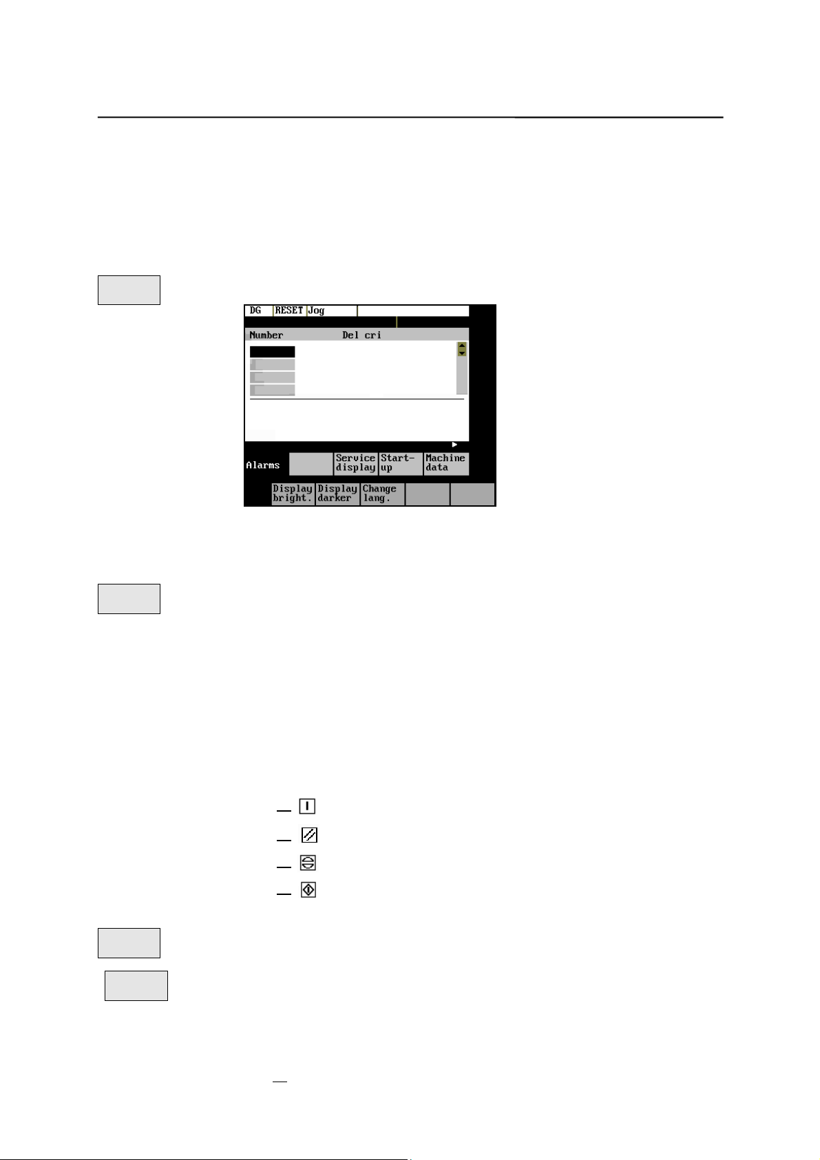
Services and Diagnosis
7.2 Diagnosis and start-up – “Diagnostics” operating area
Functionality
In the “Diagnostics” operating area, you can call service and diagnostic
functions, set start-up switches, etc.
Operating sequence
Diagnostics
Selecting the Diagnostics softkey will open the Diagnostics main screen.
Fig.7-4 Diagnostics main screen
Softkeys
Alarms
for diagnostic functions
This window displays all pending alarms line by line, starting with the alarm
with the highest priority.
Alarm number, cancel criterion and error text are displayed. The error text
refers to the alarm number on which the cursor is positioned.
Explanations with regard to the screenform above:
Number
z
The “Number” item displays the alarm number. The alarms are displayed
in chronological sequence.
Cancel criterion
z
The symbol of the key required to reset the alarm is displayed for every
alarm.
Text The alarm text is displayed.
z
Service Axes
Service
display
Service
axes
The
The window displays information about the axis drive.
SINUMERIK 802S/C base line
Operation and Programming Milling
Switch the device off and on again.
Press the RESET key.
Press the “Acknowledge alarm“ key.
Alarm is reset by NC STAR T.
window appears on the screen.
7-7
Page 90

Services and Diagnosis
Fig. 7–5 The “Service Axes” window
In addition, the Axis+ and Axis– softkeys are displayed. They can be used to
call the values for the next or previous axis.
Servo
trace
To optimize the drives, an oscillograph function is provided for graphical
representation of the velocity setpoint. The velocity setpoint corresponds to the
±10V interface.
The start of recording can be linked with various criteria which permit recording
in parallel to internal conditions of the control system. The setting needed for
this option must be carried out in the “Select Signal” function.
The following functions can be used to analyze the result:
Change scaling of abscissa and ordinate,
z
Measure value by means of a horizontal or vertical marker,
z
Measure the abscissa and ordinate values as a difference between two
z
marker positions.
Fig.7-6 The “Servo Trace” main screen
The heading of the diagram contains the current graduation of abscissa and
ordinate, the current measured positions and the difference values of the
markers.
The displayed diagram can be moved within the visible screen area by means
of the cursor keys.
7-8
Operation and Programming
SINUMERIK 802S/C base line
Milling
Page 91

Services and Diagnosis
Graduation
of abscissa
Initial values
Current
marker
position
Fig.7-7 Meaning of the fields
Select
signal
Use this menu to select the axis to be measured, the measuring time, threshold
value, pre-trigger/post-trigger time and trigger conditions. The signal settings
are fixed.
Graduation
of ordinate
Difference
display
of Markers
Fig.7-8 Signal selection
Selecting the axis: The axis is selected in the Axis toggle field.
z
Signal type:
z
Velocity setpoint
Actual position value of measuring system 1
Following error
Determining the measuring time: The measuring time is entered in ms
z
directly in the “Measuring Time” input field.
Determining trigger time to or after
z
With input values < 0, recording starts by the set time prior to the trigger
event, and with values > 0 accordingly after the trigger event, whereby
the following conditions must be observed:
Trigger time + measuring time
Selecting the trigger condition: Position the cursor on the Trigger
z
Condition field and select the condition using the toggle key.
No trigger, i.e. the measuring starts immediately after pressing the
Start softkey.
Negative edge
Exact stop fine reached
Exact stop coarse reached
SINUMERIK 802S/C base line
Operation and Programming Milling
7-9
Page 92

Services and Diagnosis
Determining the trigger threshold: The threshold is entered directly in the
z
Threshold input field. It acts only for the trigger conditions “Positive
edge“ and “Negative edge”.
Marker
This function branches to another softkey level, in which the horizontal or
vertical marker can be switched on or off. The markers are displayed in the
status bar.
The markers are moved in steps of one increment by means of the cursor keys.
Larger step widths can be set in the input fields. The value specifies the
number of raster units per <SHIFT> + cursor movement by which the marker
is to be moved.
If a marker reaches the margin of the diagram, the next raster in horizontal or
vertical direction is automatically pulled down.
Fig.7-9 Setting the markers
The markers can also be used to determine the differences in the horizontal or
vertical direction. To this aim, position the marker on the start point and press
either the Fix H - Mark. or the Fix T- Mark. softkey. The difference between the
start point and the current marker position is now displayed in the status bar.
The softkey labeling changes to “Free H - Mark.” or “Free T - Mark” .
Help
Pressing this functions calls explanations with regard to the displayed values
on the screen.
Start
Pressing the Start softkey starts recording. The softkey labeling changes to
Stop. The note “Recording active” is displayed.
When the measuring time is elapsed, the softkey labeling changes to Start.
Pressing the Stop softkey aborts the current measuring. The softkey labeling
Stop
Zoom
Time +
1, 2, 5, 10, 20, 50, 100, 200, 500, 1,000 ms/div.
Zoom
Time –
Zoom
V +
Zoom
0.01, 0.05, 0.1, 0.5, 1, 5, 10, 50, 100, 500, 1,000, 5,000 unit/ div
V –
Auto.
scaling
Version
changes to Start.
The scaling changes in the following steps:
The horizontal scaling changes in the following steps:
This function calculates the vertical scaling from the peak values.
This window contains the version numbers and the creation date of the
individual CNC components.
7-10
SINUMERIK 802S/C base line
Operation and Programming
Milling
Page 93

Services and Diagnosis
Type
displays the control type
Fig. 7–10 Control type
OEM
displays the OEM picture here.
Softkeys
for start-up function s
Note
See also Technical Manual
Start-up
The start-up function branches to the following softkey functions:
Fig.7-11
SINUMERIK 802S/C base line
Operation and Programming Milling
7-11
Page 94

Services and Diagnosis
Start-up
switch
You can assign the system powe r-up parameters various parameters.
Start-up switch
Caution
!
Changes in the start-up branch have a considerable influence on the machine.
Selecting the power-up mode of the NC.
NC
Fig.7-12 NC start-up
PLC
Fig.7-13 PLC start-up
The PLC can be started in the following modes:
Restart
z
General reset
z
In addition, it is possible to link the selected mode with
subsequent simulation or
z
subsequent debugging mode.
z
OK
Use the OK key to start the NC start-up.
Return to the Start-up main screen without further action by RECALL.
Edit
PLC txt
This function can be used to insert or modify PLC alarm messages. Select the
desired alarm number using the softkey function “Next Number”. The text
currently valid is displayed in the window and in the input line.
7-12
SINUMERIK 802S/C base line
Operation and Programming
Milling
Page 95

Services and Diagnosis
Fig.7-14 Screenform for editing a PLC alarm text
Enter the new text in the input line. Complete your input by pressing INPUT.
For the notation of the texts refer to the Start-up Guide.
Next
Number
Search
Number
Save &
Exit
Recall
This function selects the next following text number for editing. When the last
text number is reached, the process restarts with the first number.
This function selects the entered number for editing.
Pressing this function saves the modified texts. The editor is then quitted.
The editor is quitted without saving the changes.
Editing Chinese characters
This function is only available if a Chinese character set is loaded.
The editor shows a section of Chinese characters. Use the cursor to navigate
in the list. If the character you are looking for is not contained in the section,
another section can be selected using the letters A - Z. Pressing softkey 4
takes over the desired character to the input line. In this mode, Latin letters
cannot be entered.
Fig.7-15 Screen form for editing a PLC alarm text in Chinese
The following softkey functions are realized:
Next
Number
Search
Number
This function selects the next following text number for editing. When the last
text number is reached, the process restarts with the first number.
This function selects the entered number for editing.
SINUMERIK 802S/C base line
Operation and Programming Milling
7-13
Page 96

Services and Diagnosis
Change
Mode
Choose
Char
Save &
Exit
Recall
STEP 7
connect
This function toggles between the selection of the section and the input of Latin
letters.
Pressing this softkey accepts the selected character into the input line.
Pressing this softkey saves the modified texts. The editor is then quitted.
The editor is quitted without saving the changes.
The S7-Conn menu can be used to link the PLC with the external programming
package S7-200.
If the RS232 interface is already occupied by the data transfer, you can link the
control system with the programming package only when the transmission is
completed.
When the link is activated, the RS232 interface is initialized. The following
interface parameters are defined by the used program:
Device RTS - CTS
Baud rate 38400
Stop bits 1
Parity even
Data bits 8
Fig.7-16 S7-200 connection
Conn.
on
Conn.
The active or inactive condition, respectively, is maintained even if Power On is
off
This function activates the connection between the PC and the control system.
The softkey labeling changes to Connection off (Conn. of f).
carried out (except for booting with default data).
Press RECALL to quit the menu.
PLC
status
7-14
Operation and Programming
You can display information about the current states of PLC memory cells
listed below; if desired they can be altered.
SINUMERIK 802S/C base line
Milling
Page 97

Services and Diagnosis
It is possible to display 6 operands simultaneously.
Inputs I Input byte (IBx), input word (Iwx), input double word (IDx)
Outputs Q Output byte (Qbx), output word (Qwx), output double word
(QDx)
Bit
memories
M Memory byte (Mx), memory word (Mw), memory double
word (MDx)
Timers T Timer (Tx)
Counters C Counter (Zx)
Data V Data byte (Vbx), data word (Vwx), data double word (VDx)
Format B
Binary
H
Hexadecimal
D
Decimal
Binary representation cannot be used for double words.
Counters and timers are displayed in decimal format.
Fig.7-17 PLC status display
There are further softkeys provided under this menu item.
Edit
z
Cyclic updating of the values is interrupted. You can then edit the
operand values.
Cancel
z
Cyclic updating continues without the entered values being transferred to
the PLC.
Accept
z
The entered values are transferred to the PLC; cyclic updating continues.
Delete
z
All operands are deleted.
Operand +
z
The address of the operand can be incremented in steps of 1.
Operand –
z
The address of the operand can be decremented in steps of 1.
Set
password
There are four different password levels implemented by the control system,
Set password
thereby allowing four different levels of access authorization:
Siemens password
z
System password
z
SINUMERIK 802S/C base line
Operation and Programming Milling
7-15
Page 98

Services and Diagnosis
M
Manufacturer password
z
User password
z
You can edit the data depending on your level of access authorization (refer
also to the Technical Manual)
DEMO.
Enter the password.
If you do not know the password, you will not be granted access.
The password is set when you press the OK softkey.
You can return to the Start-up main screen without saving your input by
selecting RECALL.
Delete
password
Change
password
The access authorization is reset.
Change password
Fig.7-18
Depending on the access authorization, various options for changing the
password are provided in the softkey bar.
Use the softkeys to select the password level. Enter the new password and
complete your input with OK.
The system asks you to confirm the new password again.
Press OK to complete the password change.
You can return to the Start-up main screen without saving your input by
RECALL.
Save
data
This function saves the contents of the volatile memory to a non-volatile
Save data
memory area.
Prerequisite: No program is currently being run.
It is not allowed to perform any operating actions while saving data.
7-16
SINUMERIK 802S/C base line
Operation and Programming
Milling
Page 99

Services and Diagnosis
Softkeys
Machine data (see also Tech nical Manual)
Machine
data
for service functions
Fig.7-19
Changes to the machine data have a considerable influence on the machine.
Incorrect parameter settings can result in irreparable damage to mechanical
components.
Units
userdef User-defined
m/s**2 Meters per second
U/s**3 Revolutions per second
sSecond
Kgm**2 Moment of inertia
mH Inductivity
Nm Torque
us Microseconds
uA Microamperes
uVs Microvolt seconds
Effectiveness
so Effective immediately
cf With confirmation
re Reset
po Power ON
General
MD
Open the General Machine Data window. Use the paging keys to page up and
General machine data
down.
Axis
MD
Open the Axis-Specific Machine Data window. The softkey bar is extended by
Axis-specific machine data
the Axis + and Axis – softkeys.
Fig.7-20
The data of the axis are displayed.
SINUMERIK 802S/C base line
7-17
Operation and Programming Milling
Page 100

Services and Diagnosis
Other
MD
Open the Other Machine Data window. Use the paging keys to page up and
Other machine data
down.
Display MD
Display machine data
Open the Display Machine Data window. Use the paging keys to page up and
down.
Search
Search
Enter the number or name of the machine data you want to find and press
Input.
The cursor jumps to the target data.
Fig.7-21
Continue
search
The search for the next number or name continues.
Axis +
Axis –
Active
MD
Active
MD
Display
bright.
This softkey can be used to adjust the brightness of the screen.
Display
The power-up setting can be input via a display machine data. The adjustment
darker
The Axis + and Axis – softkeys are used to switch over to the machine data
area of the next or previous axis.
This softkey is used to activate the machine data marked with “cf” .
This softkey can be used to activate the machine data marked with “cf”.
Brightness
via these softkeys does not effect the setting in the display machine data.
Change
lang.
Use the Change lang. softkey to switch between foreground and background
Switching the language
languages.
7-18
SINUMERIK 802S/C base line
Operation and Programming
Milling
 Loading...