

Page 1
Overview of Controls
1
SINUMERIK 802S/C
Manual Machine
Operator’s Guide
Sequence of
Operations
Tool Data
Functions
Service Functions
Saving Data
Switching to the
Standard Operator
Interface
2
3
4
5
6
7
Valid for
Software Version
SINUMERIK 802S/C 3.1.0 or higher
Shutting Down the
Controller
Menu Tree
Messages
8
9
10
04/2005 Edition
Page 2

SINUMERIK® Documentation
Printing history
Brief details of this edition and previous editions are listed below.
The status of each edition is indicated by the code in the "Remarks" column.
Status code in the "Remarks" column:
A .... New documentation.
B .... Unrevised reprint with new order number
C .... Revised edition with new status
Edition Order No. Remarks
04/2005 ---
Trademarks
SIMATIC®, SIMATIC HMI®, SIMATIC NET®, SIROTEC®, SINUMERIK® and SIMODRIVE® are registered
trademarks of Siemens AG. Other names used in this publication may be trademarks, which, if used by third
parties for their own means, may violate the rights of their owners.
A
Additional information is available in the Internet at:
http://www.siemens.com/motioncontrol
This publication has been produced using WinWord V 8.0,
Designer V 7.0 and the DocuTool AutWinDoc.
© Siemens AG, 2005. All rights reserved
Order No. --Printed in Germany
Other functions not described in this documentation may be
executable in the control
obligation to supply such functions with a new control or when
servicing.
We have checked the contents of this manual for agreement with the
hardware and software described. Nevertheless, differences might
exist and we cannot, therefore, guarantee that they are completely
identical. However, the data in this manual are reviewed regularly and
any necessary corrections included in subsequent editions.
Suggestions for improvement are welcome.
Technical data subject to change.
Siemens Aktiengesellschaft
. This does not, however, represent an
Page 3

04/2005 Preface
Preface
SINUMERIK documentation
The SINUMERIK documentation is organized in 3 parts:
• General documentation
• User documentation
• Manufacturer/Service documentation
Please contact your local Siemens office for more detailed information about other
SINUMERIK 802D publications.
An overview of publications that is updated monthly is provided in a number of
languages in the Internet at:
http://www.siemens.com/motioncontrol
Follow menu items "Support" Æ "Technical Documentation" Æ "Overview of
Documents".
The Internet version of the DOConCD (DOConWEB) is available at:
http://www.automation.siemens.com/doconweb
Target readership
This Manual is intended for machine-tool users. This publication provides detailed
information that the user requires for operating the SINUMERIK 810D and 840D
controls.
Standard scope
This Operator’s Guide describes the functionality of the standard scope.
Extensions or changes made by the machine tool manufacturer are documented by
the machine tool manufacturer.
Other functions not described in this documentation may be executable in the
control. This does not, however, represent an obligation to supply such functions
with a new module or when servicing.
© Siemens AG, 2005. All rights reserved
SINUMERIK 802S/C BA_MM (BA) – 04/2005 Edition
iii
Page 4
Preface 04/2005
Hotline
If you have any questions, please get in touch with our Hotline:
A&D Technical Support
Phone.: +49 (0) 180 / 5050 - 222
Fax: +49 (0) 180 / 5050 - 223
E-mail: mailto:adsupport@siemens.com
Internet: http://www.siemens.com/automation/support-request
If you have any queries (suggestions, corrections) in relation to this documentation,
please fax or e-mail us:
Fax: +49 (0) 9131 / 98 - 63315
E-mail: mailto:motioncontrol.docu@siemens.com
Fax form: See the reply form at the end of the document.
SINUMERIK Internet address
http://www.siemens.com/motioncontrol
Safety notes
This Manual contains information which you should carefully observe to ensure
your own personal safety and the prevention of material damage. The notices are
highlighted by a warning triangle The warnings are shown below in decreasing
order of danger.
!
!
!
Danger
Indicates an imminently hazardous situation which, if not avoided, will result in
death or serious injury or in substantial property damage.
Warning
Indicates a potentially hazardous situation which, if not avoided, could result in
death or serious injury or in substantial property damage.
Caution
Used with the safety alert symbol indicates a potentially hazardous situation
which, if not avoided, may result in minor or moderate injury or in property
damage.
© Siemens AG, 2005. All rights reserved
iv SINUMERIK 802S/C BA_MM (BA) – 04/2005 Edition
Page 5

04/2005 Preface
Caution
Used without safety alert symbol indicates a potentially hazardous situation
which, if not avoided, may result in property damage.
Notice
Used without the safety alert symbol indicates a potential situation which, if not
avoided, may result in an undesirable result or state.
If several hazards of different degrees occur, the hazard with the highest degree
must always be given preference. If a warning note with a warning triangle warns of
personal injury, the same warning note can also contain a warning of material
damage.
Qualified personnel
Start-up and operation of the device/equipment/system in question must only be
performed using this documentation. The device/system must only be
commissioned and operated by qualified personnel. Qualified personnel as
referred to in the safety guidelines in this documentation are those who are
authorized to start up, earth and label units, systems and circuits in accordance
with the relevant safety standards.
Proper use
!
Note the following:
Warning
The device must only be used for the applications described in the Catalog and
only in combination with the equipment, components and devices of other
manufacturers as far as this is recommended or permitted by Siemens. It is
assumed that this product be transported, stored and installed as intended and
maintained and operated with care to ensure that the product functions correctly
and properly.
© Siemens AG, 2005. All rights reserved
SINUMERIK 802S/C BA_MM (BA) – 04/2005 Edition
v
Page 6

Preface 04/2005
Other information
!
Important
This notice indicates important facts that must be taken into consideration.
Note
This symbol always appears in this documentation where further, explanatory
information is provided.
Machine manufacturer
This pictorial symbol always appears in this document to indicate that the
machine manufacturer can affect or modify the function described. Note the
machine manufacturer’s instructions.
© Siemens AG, 2005. All rights reserved
vi SINUMERIK 802S/C BA_MM (BA) – 04/2005 Edition
Page 7

04/2005 Contents
Contents
1 Overview of Controls...................................................................... 1-9
1.1 Operator panel.............................................................................. 1-10
1.1.1 Key functions ............................................................................. 1-10
1.1.2 Controls on the machine............................................................ 1-11
2 Sequence of Operations ................................................................ 2-13
2.1 Powering-up the control................................................................ 2-14
2.2 Reference point approach ............................................................ 2-14
2.2.1 Preparations for reference point approach ................................ 2-14
2.2.2 Moving the axes ahead of the reference point .......................... 2-15
2.2.3 Reference point approach ......................................................... 2-16
2.3 Manual Machining......................................................................... 2-17
2.3.1 Displays on the main "Manual Machining" screen:.................... 2-18
2.3.2 Toggling the display................................................................... 2-19
2.3.3 Machining with the handwheels................................................. 2-20
2.3.4 Handwheel valuation setting...................................................... 2-20
2.3.5 Machining with the 4-way switch/axis direction keys................. 2-20
2.3.6 Spindle advance/reverse ........................................................... 2-21
2.3.7 Jog spindle................................................................................. 2-21
2.3.8 Tool change ............................................................................... 2-22
2.3.9 Machining technology data........................................................ 2-23
2.3.10 Changing the spindle/feedrate value ....................................... 2-24
2.3.11 Entering machining technology data: ...................................... 2-25
2.3.12 Spindle positioning................................................................... 2-27
3 Tool Data.......................................................................................... 3-29
3.1 Tool list.......................................................................................... 3-30
3.2 Tool calibration.............................................................................. 3-31
3.3 Geometry tool data ....................................................................... 3-32
3.4 Entering tool technology data ....................................................... 3-33
3.5 Deleting tool technology data ....................................................... 3-35
4 Functions......................................................................................... 4-37
4.1 Limit stops..................................................................................... 4-38
4.1.1 Setting limit stops....................................................................... 4-38
4.1.2 Activating/disabling limit stops ................................................... 4-40
4.1.3 Turning against mechanical stoppage....................................... 4-41
© Siemens AG, 2005. All rights reserved
Sinumerik 802S/C BA_MM (BA) – 04/2005 Edition
vii
Page 8

Contents 04/2005
4.2 Taper turning................................................................................. 4-42
4.3 Radius turning............................................................................... 4-44
4.4 Drilling - centered.......................................................................... 4-46
4.5 Tapping ......................................................................................... 4-49
4.6 Groove cycles/parting ................................................................... 4-53
4.6.1 Groove cycle - single ................................................................. 4-53
4.6.2 Groove cycle - multiple .............................................................. 4-57
4.6.3 Parting........................................................................................ 4-59
4.6.4 Multiple parting .......................................................................... 4-60
4.7 Thread cutting.............................................................................. 4-61
4.7.1 Longitudinal thread cutting......................................................... 4-61
4.7.2 Thread recutting......................................................................... 4-65
4.7.3 Thread shaving after thread cutting........................................... 4-67
4.8 Cutting cycles................................................................................ 4-68
4.8.1 Cutting cycle A........................................................................... 4-69
4.8.2 Cutting cycle B........................................................................... 4-73
4.8.3 Cutting cycle C........................................................................... 4-77
4.9 Setting the workpiece zero point................................................... 4-80
5 Service Functions........................................................................... 5-83
6 Saving Data ..................................................................................... 6-85
7 Switching to the Standard Operator Interface ............................. 7-87
7.1 General ......................................................................................... 7-88
7.2 "Reference Point Level" starting point .......................................... 7-88
7.3 "Manual Machining" starting point ................................................ 7-89
7.3.1 Switching back to the "Manual Machine" operator interface ..... 7-91
8 Shutting Down the Controller........................................................ 8-93
9 Menu Tree ........................................................................................ 9-95
10 Messages....................................................................................... 10-99
© Siemens AG, 2005. All rights reserved
viii Sinumerik 802S/C BA_MM (BA) – 04/2005 Edition
Page 9

04/2005 1 Overview of Controls
1.1 Operator panel
1
1 Overview of Controls
1.1 Operator panel.............................................................................. 1-10
1.1.1 Key functions ............................................................................. 1-10
1.1.2 Controls on the machine............................................................ 1-11
© Siemens AG, 2005. All rights reserved
SINUMERIK 802S/C BA_MM (BA) – 04/2005 Edition
1-9
Page 10
1 Overview of Controls 04/2005
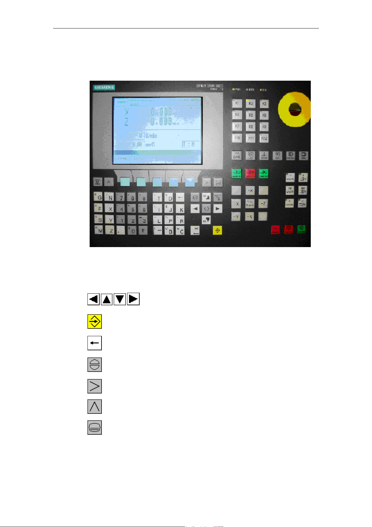
1.1 Operator panel
1.1 Operator panel
Fig. 1-1: Operator panel
1.1.1 Key functions
Move cursor in the direction of the arrow
Enter key (accept entry values)
Delete character (from right to left)
Acknowledge alarm
Extended menu (only if the corresponding symbol appears
on the screen)
Back key
(only if the corresponding symbol appears on the screen)
Monitor key, used exclusively for switching to the standard
operator interface (Sinumerik 802S/C base line).
© Siemens AG, 2005. All rights reserved
1-10 SINUMERIK 802S/C BA_MM (BA) – 04/2005 Edition
Page 11

04/2005 1 Overview of Controls
1.1 Operator panel
Key not used for machine operation
Toggle key for handwheel valuation
JOG key for selecting “JOG” mode
1.1.2 Controls on the machine
(if provided by the machine manufacturer)
• NC start key
• NC stop key
• 4-way switch or axis direction keys (X+/X-/Z+/Z-) for axis movement
• Rapid traverse override switch or key for axis movement
• Spindle joystick or spindle direction keys for spindle control (clockwise or
counterclockwise rotation)
• Jog spindle key
• Handwheel for X and Z axis
• Emergency Stop button
© Siemens AG, 2005. All rights reserved
SINUMERIK 802S/C BA_MM (BA) – 04/2005 Edition
1-11
Page 12

1 Overview of Controls 04/2005
1.1 Operator panel
© Siemens AG, 2005. All rights reserved
1-12 SINUMERIK 802S/C BA_MM (BA) – 04/2005 Edition
Page 13

04/2005 2 Sequence of Operations
2.1 Powering-up the control
2
2 Sequence of Operations
2.1 Powering-up the control................................................................ 2-14
2.2 Reference point approach ............................................................ 2-14
2.2.1 Preparations for reference point approach ................................ 2-14
2.2.2 Moving the axes ahead of the reference point .......................... 2-15
2.2.3 Reference point approach ......................................................... 2-16
2.3 Manual Machining......................................................................... 2-17
2.3.1 Displays on the main "Manual Machining" screen:.................... 2-18
2.3.2 Toggling the display................................................................... 2-19
2.3.3 Machining with the handwheels................................................. 2-20
2.3.4 Handwheel valuation setting...................................................... 2-20
2.3.5 Machining with the 4-way switch/axis direction keys................. 2-20
2.3.6 Spindle advance/reverse ........................................................... 2-21
2.3.7 Jog spindle................................................................................. 2-21
2.3.8 Tool change ............................................................................... 2-22
2.3.9 Machining technology data........................................................ 2-23
2.3.10 Changing the spindle/feedrate value ....................................... 2-24
2.3.11 Entering machining technology data: ...................................... 2-25
2.3.12 Spindle positioning................................................................... 2-27
© Siemens AG, 2005. All rights reserved
SINUMERIK 802S/C BA_MM (BA) – 04/2005 Edition
2-13
Page 14
2 Sequence of Operations 04/2005
2.1 Powering-up the control
2.1 Powering-up the control
Unless the machine manufacturer has set it up differently, the controller powers up
automatically when the power supply is switched on. Internal test routines are
performed during the power-up process. Once they have been successfully
completed, the controller opens and displays the Reference Point screen form.
2.2 Reference point approach
Once the controller has powered up, the Reference Point screen form appears:
Fig. 2-1: Reference point approach
!
Note
Before starting the reference point approach, be sure to move the machine slide
to a position from which the reference point can be approached in a positive axis
direction.
2.2.1 Preparations for reference point approach
Before you can approach the reference points for the two axes, the following
conditions must be met:
Prerequisite
• There must be no NC alarms pending!
→ Clear any that are pending by pressing the "Reset" function key.
• All machine axes must be in a position from which the reference point can be
reached in a positive traversing direction.
→ In manual mode, use the handwheels to move the axes to the appropriate
position ahead of the reference point.
© Siemens AG, 2005. All rights reserved
2-14 SINUMERIK 802S/C BA_MM (BA) – 04/2005 Edition
Page 15
04/2005 2 Sequence of Operations
2.2 Reference point approach
2.2.2 Moving the axes ahead of the reference point
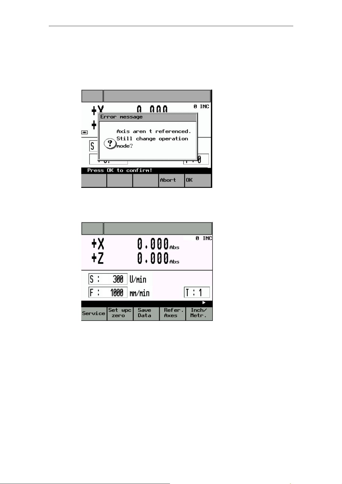
• Exit the Reference Point screen form by pressing the "End Refpkt" function key.
The following prompt appears:
Fig. 2-2: Exiting the Reference Point Approach screen
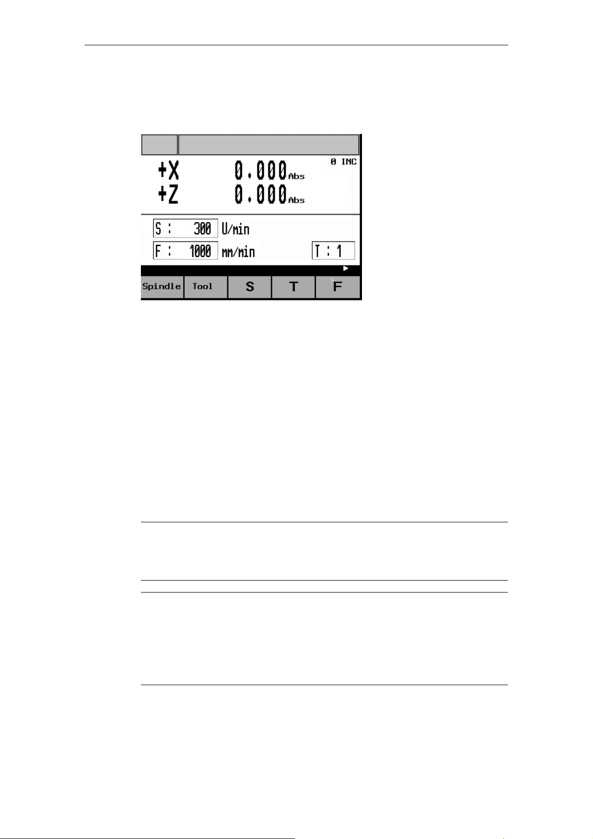
• Press "OK" to acknowledge the message and return to the main service
functions menu.
Fig. 2-3: Main Service Functions screen
• Press the “JOG” key once (otherwise, it will not be possible to switch to handwheel valuation).
• Then use the toggle key to set the handwheel valuation. The current setting will
appear on the top-right of the screen (e.g., 100 INC).
• Then use the handwheel to move the axes to a position from which they can
approach the reference point in a positive direction.
© Siemens AG, 2005. All rights reserved
SINUMERIK 802S/C BA_MM (BA) – 04/2005 Edition
2-15
Page 16

2 Sequence of Operations 04/2005
2.2 Reference point approach
Caution
In this operating mode the axes can only be approached using the handwheel.
Use of the 4-way switch or axis direction keys to move the axes is blocked. In
addition, the spindle cannot be started in this mode.
• Press the “Refer. Axes” function key to switch back to “Reference point
approach” mode.
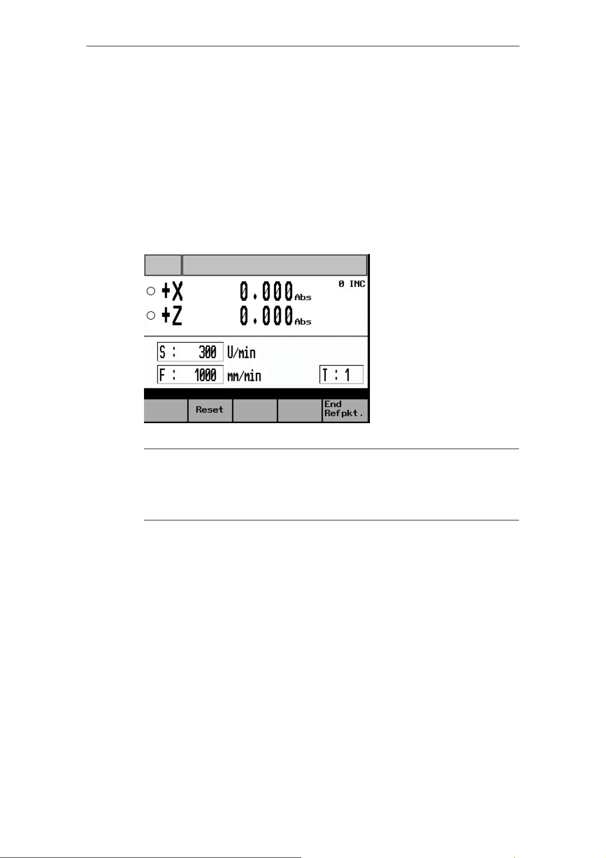
2.2.3 Reference point approach
Displays
Axis has not yet been referenced
Axis has already reached the reference point (is referenced)
Once all the conditions have been met (→ Preparations for reference point
approach), reference point approach can be started for each axis as follows:
• Using the 4-way switch or axis direction key, start the X axis in the positive
direction (X+). The reference point for the X axis is then approached
automatically.
• At the end of this process the axis stops automatically and the symbol is
displayed in front of the axis name.
• Once the X axis has reached its reference point, the same process can be
repeated for the Z axis (Z+).
!
Note
The axes must be referenced in this sequence, i.e. the X axis first, followed by
the Z axis. Any other sequence will not be accepted by the controller.
Caution
If the machine manufacturer has not fitted an axis limit switch, there is a risk of a
mechanical collision if the axis is on the wrong side of the reference point cam
before the start of the reference point approach.
→ Preparations for reference point approach.
• Press the "End Refpkt." function key once both axes have been referenced to
return to the main "Manual Machining" screen.
© Siemens AG, 2005. All rights reserved
2-16 SINUMERIK 802S/C BA_MM (BA) – 04/2005 Edition
Page 17
04/2005 2 Sequence of Operations
2.3 Manual Machining
2.3 Manual Machining
The main Manual Machining screen looks like this:
Fig. 2-4: Main "Manual Machining" screen
Manual workpiece machining is carried out in this operating mode.
Here the cross-slide is controlled either
• By means of the handwheels for the X and Z axis (→ Machining with the
handwheels) or
• By means of the 4-way switch or the axis direction keys (X+/X-/Z+/Z-)
(→ Machining with the 4-way switch/axis direction keys)
The spindle is controlled by means of
• The spindle joystick or the individual spindle advance and spindle reverse keys
(→ Spindle advance/reverse).
Machining technology data such as spindle speed, cutting speed and feedrate
must be set via special screen forms.
→ Machining technology data.
!
Note
Generally speaking the relevant machining technology data must be entered
before starting manual machining.
Caution
The maximum permissible spindle speed, which depends on the chucking device
fitted, must be entered in the Machining Technology Data screen form!
Failure to pay sufficient attention to this point can lead to serious damage as a
result of the chucking device speed being exceeded.
→ Machining technology data.
© Siemens AG, 2005. All rights reserved
SINUMERIK 802S/C BA_MM (BA) – 04/2005 Edition
2-17
Page 18

2 Sequence of Operations 04/2005
2.3 Manual Machining
2.3.1 Displays on the main "Manual Machining" screen:
Actual-value
display:
The current actual position for the X and Z axis is shown here.
If the abbreviation "Abs" appears after the position value, the
display shows the absolute machine position. If the
abbreviation "Rel" appears here, however, it is a relative
position reflecting the distance traversed since the display was
last reset.
→ Toggling the display.
Traversing
direction:
If the axis is moving, the current traversing direction is indicated
by the appropriate sign (+/-) in front of the axis letter (X/Z).
S value: The programmed value for either the spindle speed (Rev/min)
or the cutting speed (m/min) is shown here. The display
corresponds to the settings for the machining technology data.
→ Machining technology data.
F value: The programmed feedrate is displayed here in either "m/min" or
"mm/Rev", depending on the settings for the machining
technology data.
→ Machining technology data.
T value: The tool offset used by the controller is shown here.
→ Tool change.
INC value: Indicates the handwheel pulse weighting currently set.
→ Machining with the handwheels
© Siemens AG, 2005. All rights reserved
2-18 SINUMERIK 802S/C BA_MM (BA) – 04/2005 Edition
Page 19
04/2005 2 Sequence of Operations
2.3 Manual Machining
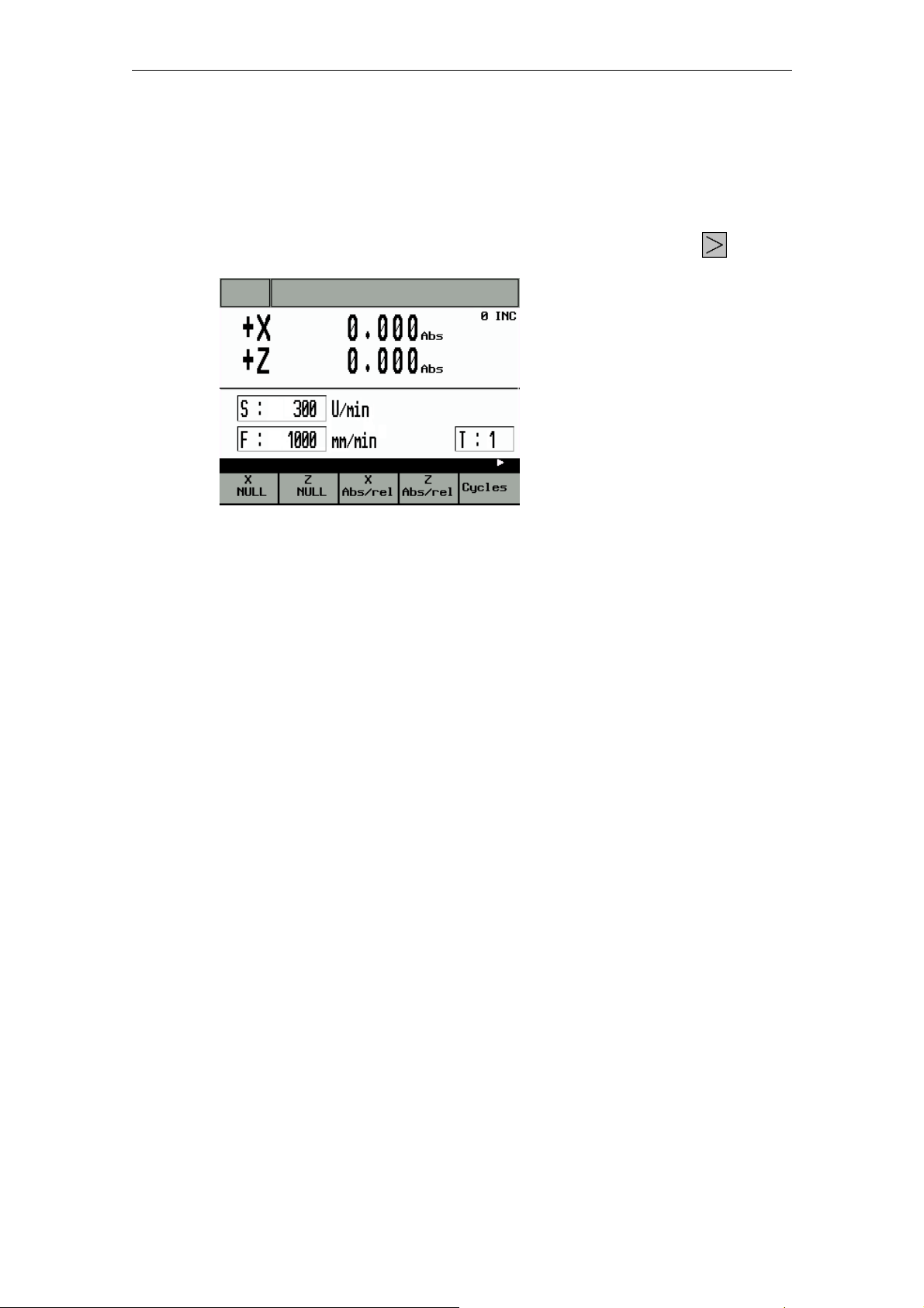
2.3.2 Toggling the display
The radius turning function is accessed from the main "Manual Machining" screen
(Fig. 4) as follows:
• Change the function key bar by pressing the "Extended menu" key
Fig. 2-5: Main service “toggling the display”
Press the function keys shown to alter the display as follows:
“X NULL”: Press the "X=0" or "Z=0" key to change the actual value display
to "relative position display" and reset the display in the
corresponding axis.
“Z NULL”: Press the "X=0" or "Z=0" key to change the actual value display
to "relative position display" and reset the display in the
corresponding axis.
twice:
"X Abs./rel.”: Press the "abs./rel." key to toggle the actual value display
between "absolute position display" and "relative position
display" in the corresponding axis.
"Z Abs./rel.”: Press the "abs./rel." key to toggle the actual value display
between "absolute position display" and "relative position
display" in the corresponding axis.
© Siemens AG, 2005. All rights reserved
SINUMERIK 802S/C BA_MM (BA) – 04/2005 Edition
2-19
Page 20

2 Sequence of Operations 04/2005
2.3 Manual Machining
2.3.3 Machining with the handwheels
The handwheels for the X and Z axis are not mechanically connected to the feed
screws. Electronic pulse generators mounted on the handwheels generate the
information needed by the controller to execute the required traversing movement.
The handwheels are only active when the 4-way switch is in the zero position and
the individual axis control keys are disabled.
The distance traversed per handwheel pulse depends on the handwheel valuation
setting.
→ Handwheel valuation setting.
!
Note
If the handwheel valuation is set to "0" or if the feedrate override switch is in the
"0" position, the handwheels are disabled.
2.3.4 Handwheel valuation setting
Press the “Toggle key for handwheel valuation” in the main “Manual Machining”
screens to set the handwheel valuation.
The current setting will appear on the top-right of the screen (e.g., 100 INC).
If you are unable to adjust the handwheel valuation setting, it will be because the
controller's internal mode is incompatible with this process. Press the “JOG” key
once to resolve the problem.
Caution
An incorrect handwheel valuation setting can result in damage to the workpiece,
tool and machine.
2.3.5 Machining with the 4-way switch/axis direction keys
The axis can be traversed in the desired direction by turning the 4-way switch or
pressing the appropriate axis direction key. The feedrate at which the axis is
traversed depends on the settings in the Machining Technology Data screen form.
The axis feedrate is also influenced by the feedrate override switch setting and,
depending on the option selected in the Machining Technology Data screen form
(Rev. feedrate/cutting speed), by the spindle override switch.
© Siemens AG, 2005. All rights reserved
2-20 SINUMERIK 802S/C BA_MM (BA) – 04/2005 Edition
Page 21

04/2005 2 Sequence of Operations
2.3 Manual Machining
If rapid traverse overlay is also actuated, the axis is moved at the maximum
possible speed unless a different value has been set at the feedrate override
switch.
!
Note
If the feedrate override switch is set to "0", any type of axis movement is blocked.
With the "Rev. feedrate" and "cutting speed" settings, the feed is blocked until the
spindle reaches the setpoint speed.
2.3.6 Spindle advance/reverse
The spindle is started in the appropriate direction (spindle advance/reverse) by
moving the spindle joystick or actuating the corresponding spindle direction key,
provided that the chuck guard switch is enabled (chuck guard closed).
!
Note
The spindle cannot be started unless the chuck guard switch is enabled.
→ Close the chuck guard.
Caution
Handling the chuck guard/chuck guard switch can lead to injury or mechanical
damage and should be avoided.
When the spindle is switched off it brakes and comes to a halt. If a spindle brake is
fitted, it is applied. If there is no spindle brake or it is switched off, the spindle can
be rotated freely once it has stopped.
If "Spindle Positi." is selected in the "Spindle Positioning" screen form, the spindle
is moved to the specified position after being switched off.
The spindle brake, if fitted, is then applied.
→ Spindle positioning.
The programmed spindle speed can be controlled by means of an appropriate
spindle override switch setting (e.g. 50%).
2.3.7 Jog spindle
The jog spindle key (if provided by the machine manufacturer) can be used to
rotate the spindle at low speed, for example to move a workpiece to a specific
angular position.
© Siemens AG, 2005. All rights reserved
SINUMERIK 802S/C BA_MM (BA) – 04/2005 Edition
2-21
Page 22

2 Sequence of Operations 04/2005
2.3 Manual Machining
2.3.8 Tool change
In the case of conventional/cycle-controlled machines of this order of magnitude,
with just a few exceptions, a manual tool change will generally be required. For this
reason, the correct tool number (tool compensation) must be notified to the control
by hand once the real tool change has taken place at the machine.
This is done as follows:
• Press function key "T" in the main Manual Machining screen form.
• The entry field for the T value is highlighted.
• Use the numeric keypad to enter the required tool number (tool offset)
(permissible values 1-15).
• Press "Enter" to complete the process.
If no further messages appear, the controller has completed the tool change.
!
Note
The tool number (tool offset) can only be changed, if all axes and the spindle are
stationary.
Caution
The tool number (tool offset) entered in the T value field must correspond to the
tool fitted in the machine. Otherwise, the tool will have to be re-calibrated (→ Tool
calibration). An uncalibrated or incorrectly calibrated tool can lead to dimensional
errors or to incorrect cutting values.
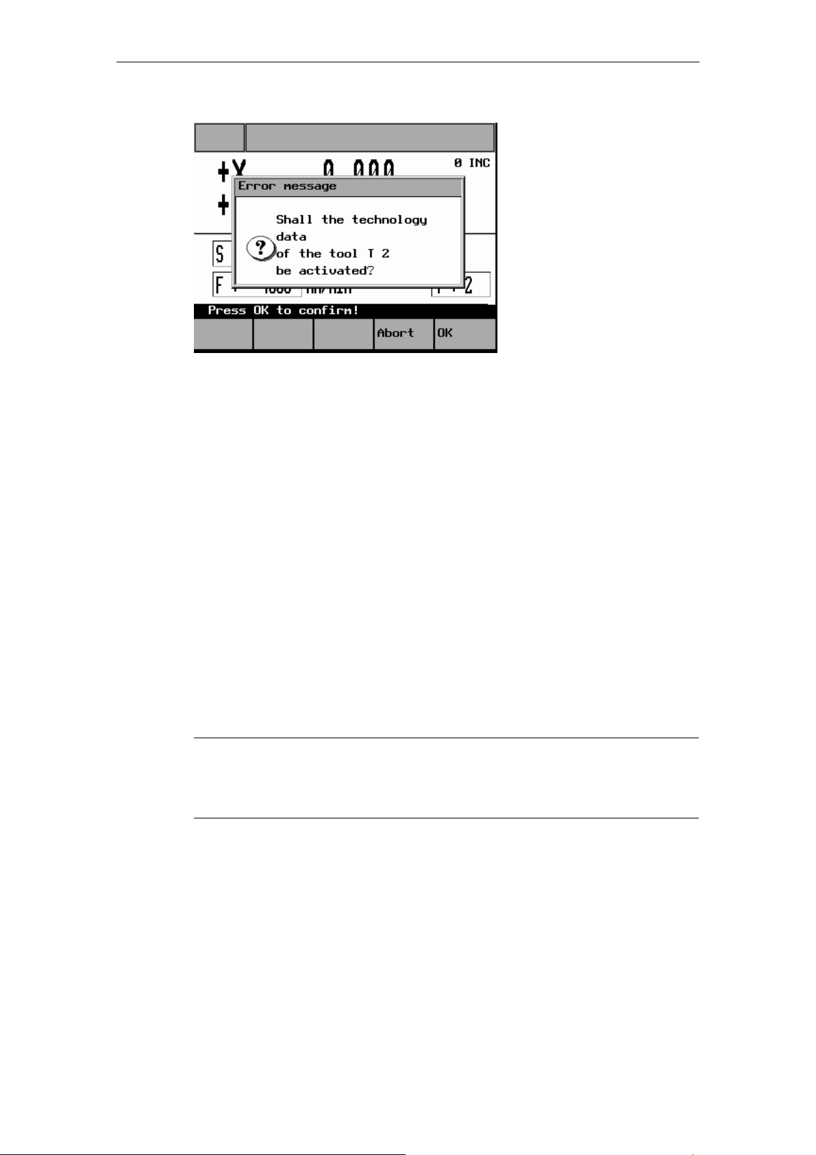
If machining technology data settings for the tool number (tool offset) to be
activated are found in the “Tool Data” screen form (→ Entering tool technology
data), the following message appears (relating to T4, in this example):
© Siemens AG, 2005. All rights reserved
2-22 SINUMERIK 802S/C BA_MM (BA) – 04/2005 Edition
Page 23
04/2005 2 Sequence of Operations
2.3 Manual Machining
Fig. 2-6: Tool technology data acceptance message
The question can be answered by pressing one of these function keys:
"OK" The tool offsets for the X and Z axis corresponding to the last tool
calibration operation are applied. The actual-value display changes,
if necessary.
The previous machining technology data is also overwritten by the
tool technology data (which has been saved for this tool) (feedrate,
spindle speed, cutting speed)
→ Entering tool technology data.
“Abort” The tool offsets for the X and Z axis corresponding to the last tool
calibration operation are applied. The actual-value display changes,
if necessary.
The previous machining technology data is retained.
2.3.9 Machining technology data
Machining technology data, such as spindle speed, cutting speed and feedrate,
defines the settings that the controller needs for the machining of workpieces.
!
Note
The machining technology data can only be changed, if all axes and the spindle
are stationary.
There are two ways of changing the machining technology data:
• Simple changes to the spindle and feedrate values (S value/F value) can be
made directly in the "Manual Machining" screen form.
→ Changing the spindle/feedrate value
© Siemens AG, 2005. All rights reserved
SINUMERIK 802S/C BA_MM (BA) – 04/2005 Edition
2-23
Page 24

2 Sequence of Operations 04/2005
2.3 Manual Machining
• A separate screen form is provided for entering the full set of machining
technology data.
→ Entering machining technology data
2.3.10 Changing the spindle/feedrate value
This method of adapting technology data can be used to change values quickly
during machining.
The values are changed using the appropriate function keys in the "Manual
Machining" screen form.
However, it is not possible to switch between "m/min" and "rev/min" (spindle) or
"mm/min" and "mm/rev" (axis) here (→ Entering machining technology data).
Changing
the S
value:
Changing
the F
value:
!
Note
The S value or F value can only be changed if all axes and the spindle are
stationary.
Press function key "S" to highlight the display field showing the
current programmed spindle value. The programmed value can now
be changed via the numeric keypad. Then press Enter to accept
(activate) the change. The entry field is deselected and the process
is complete.
To abort the change, press function key "S" or the Alarm reset key
instead of Enter. In this case the entry field is again deselected, the
new value is cleared and the previously programmed spindle value
is restored.
You cannot switch between "m/min" and "rev/min" here.
Press function key "F" to highlight the display field showing the
current programmed feedrate value. The programmed value can
now be changed via the numeric keypad. Then press Enter to
accept (activate) the change. The entry field is deselected and the
process is complete.
To abort the change, press function key "F" or the Alarm reset key
instead of Enter. In this case the entry field is again deselected, the
new value is cleared and the previously programmed feedrate value
is restored.
You cannot switch between "mm/min" and "mm/rev" here.
© Siemens AG, 2005. All rights reserved
2-24 SINUMERIK 802S/C BA_MM (BA) – 04/2005 Edition
Page 25
04/2005 2 Sequence of Operations
2.3 Manual Machining
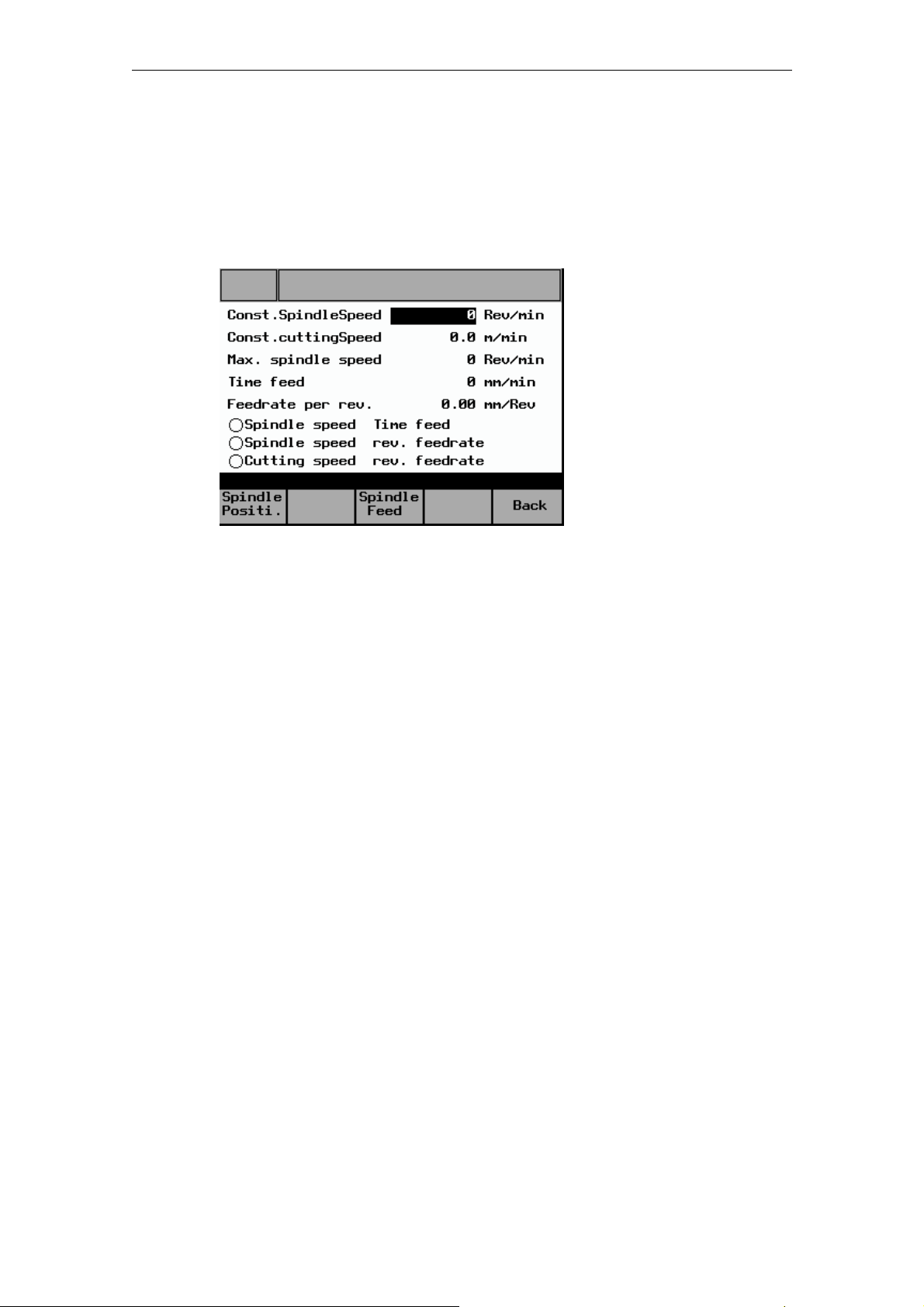
2.3.11 Entering machining technology data:
To open the screen form for machining technology data, press the "Spindle"
function key in "Manual Machining".
The following screen form appears:
Fig. 2-7: Machining technology data input
When the screen form appears, the last entry field to have been edited is
highlighted and a new value can be entered. To change a value in a different entry
field, use the cursor keys to move to that field. Enter the value via the numeric
keypad and then press Enter to accept (activate) the value. To abort the change
and restore the previous entry value, use the cursor keys to move to a different
entry field or exit the screen form (by pressing the "Back" function key), without
pressing Enter.
The meanings of the individual entry fields are defined as follows:
Const. Spindle
Speed
This entry value defines the programmed spindle speed for
machining with "Spindle speed + Time feed" or "Spindle
speed + Rev. feedrate". The value is only fully reached if no
reduction is specified via the spindle override valuation or the
spindle speed limit parameter ("Max. spindle speed").
Const. cutting
Speed
Cutting speed entry value for machining with "Cutting speed +
Rev. feedrate". The spindle speed is adjusted to the
machining diameter of the workpiece so that uniform cutting
conditions are achieved. Since the spindle would theoretically
have to rotate at an "infinitely high" speed at the rotational
center point in this mode, it has to be limited via the "Max.
spindle speed" parameter. The constant cutting speed can
also be influenced by means of the feedrate and spindle
override valuation settings.
© Siemens AG, 2005. All rights reserved
SINUMERIK 802S/C BA_MM (BA) – 04/2005 Edition
2-25
Page 26

2 Sequence of Operations 04/2005
2.3 Manual Machining
Max. spindle
speed
It is vital to enter the maximum permissible spindle speed
here. The spindle speed is then limited to this value under all
circumstances, so that the permissible chucking device
speed, for example, cannot be exceeded.
Time feed If Time feed is selected, the axes are moved at the speed
entered here (mm/min) (unless rapid traverse override is
activated). It can be influenced by the feedrate override
switch setting.
Feedrate per
rev.
The value entered here determines the axis velocity in
“Spindle speed + Rev. feedrate” or “Const. cutting speed +
Rev. feedrate” modes (if no rapid traverse override is set). It
is influenced directly by the feedrate override valuation setting
and indirectly by the spindle override valuation setting.
Caution
In the entry field for the maximum permissible spindle speed, you must enter the
value specified by the manufacturer for the chucking device that is fitted!
Failure to pay sufficient attention to this point can lead to serious damage as a
result of the chucking device speed being exceeded.
• To select the desired machining mode, press the "Spindle Feed" function key
one or more times:
"Spindle speed + Time feed" → "Spindle speed + Rev. feedrate" → "Cutting
speed + Rev. feedrate"
The symbols displayed next to the text have the following meaning:
Display:
Machining mode deselected
Machining mode active (selected)
© Siemens AG, 2005. All rights reserved
2-26 SINUMERIK 802S/C BA_MM (BA) – 04/2005 Edition
Page 27
04/2005 2 Sequence of Operations
2.3 Manual Machining
2.3.12 Spindle positioning
The Spindle positioning function is intended purely for stopping the spindle in a
specific position to facilitate fitting of the chuck guard. It is not intended for positionrelated machining.
If the Spindle positioning function is selected, the spindle is switched off and then
moved to the position specified in the "Set spindle pos." entry field. If fitted, a
spindle brake is then applied.
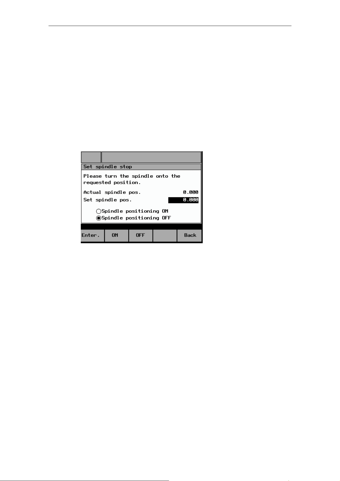
To open the “Spindle Positioning” screen form, press the "Spindle Positi." function
key in the "Machining Technology Data" screen form.
The following screen form appears:
Fig. 2-8: Spindle positioning
When the screen form appears, there are two ways to enter the position:
• Use the numeric keypad to enter the position directly in the highlighted entry
field for the "Set spindle pos.". Then press Enter to accept the value. Only
values from 0 to 359.9 are permitted; otherwise, an error message appears and
the value is not accepted.
• After switching off the spindle, rotate it manually into the required position and
press Enter. The current spindle position is displayed in the "Set spindle pos."
entry field and automatically accepted. If the spindle has not completed a full
rotation since the controller was last powered up, the spindle is not yet
synchronized and the position will therefore not be accepted. In this case, a
corresponding message is displayed.
© Siemens AG, 2005. All rights reserved
SINUMERIK 802S/C BA_MM (BA) – 04/2005 Edition
2-27
Page 28

2 Sequence of Operations 04/2005
2.3 Manual Machining
Press "ON" to activate spindle positioning and "OFF" to deactivate it.
The current status is indicated as shown below:
Display:
Function deselected
Function active (selected)
© Siemens AG, 2005. All rights reserved
2-28 SINUMERIK 802S/C BA_MM (BA) – 04/2005 Edition
Page 29

04/2005 3 Tool Data
3.1 Tool list
3
3 Tool Data
3.1 Tool list.......................................................................................... 3-30
3.2 Tool calibration.............................................................................. 3-31
3.3 Geometry tool data ....................................................................... 3-32
3.4 Entering tool technology data ....................................................... 3-33
3.5 Deleting tool technology data ....................................................... 3-35
© Siemens AG, 2005. All rights reserved
SINUMERIK 802S/802C BA_MM (BA) – 04/2005 Edition
3-29
Page 30
3 Tool Data 04/2005
3.1 Tool list
3.1 Tool list
The controller is supplied with a tool list for 15 tools as standard. However, the
individual tools must be calibrated prior to initial use.
→ Tool calibration.
Caution
An uncalibrated or incorrectly calibrated tool can lead to dimensional errors or to
incorrect cutting values! If the values entered are very different from the actual
tool values, there is a risk that the tool may break or the mechanism or workpiece
may be damaged.
To open the "Tool Data Overview", press the "Tool" function key in the main
"Manual Machining" screen form.
The following screen form appears:
Fig. 3-1: Tool data overview
The active offsets for each tool, known as the tool offsets for the X and Z axis, are
displayed in this screen form. Experienced lathe operators can use this screen
form to enter the tool offsets, as on CNC controllers. Other operators should simply
refer to this screen form for information about the current offsets. The actual tool
measuring process takes place in the "Tool Measuring" screen form.
→ Tool calibration.
Data can be entered in the "Tool Data Overview" as follows:
• Use the cursor keys to select the required field (field is highlighted)
• Select the required tool type (turning tool or drilling tool) by pressing the
"Turn-/Boretool" function key
• Enter the values and press Enter to accept. The actual value display on the
machine (in "Manual Machining") is now updated to reflect the change. If you do
not wish to accept the value entered, either use the cursor key to leave the
entry field or switch to another screen form without pressing Enter.
© Siemens AG, 2005. All rights reserved
3-30 SINUMERIK 802S/802C BA_MM (BA) – 04/2005 Edition
Page 31

04/2005 3 Tool Data
3.2 Tool calibration
3.2 Tool calibration
The supported tool calibration function is described below by reference to the X
axis of a turning tool:
• Fit the tool to be calibrated into the machine.
• In the "Manual Machining" screen form select the appropriate tool number.
→ Tool selection
• Switch to the "Tool Data Overview" screen form.
• Keep on pressing the cursor key until the relevant tool number is highlighted.
• Press the “Mess.” function key; in the case of turning tools, the following screen
form will appear:
Fig. 3-2: Tool calibration (turning tools)
• Check that the current tool number appears in the display field for the tool, since
the calibration operation will relate to this tool. If not, press the "Back" function
key to return to the "Tool Data Overview" and select the correct tool.
• With the spindle running, adjust the X handwheel carefully to "scratch" a
workpiece and then (without changing the X position) traverse the slide in the Z
axis with the handwheel (axial turning).
• Switch off the spindle.
© Siemens AG, 2005. All rights reserved
SINUMERIK 802S/802C BA_MM (BA) – 04/2005 Edition
3-31
Page 32

3 Tool Data 04/2005
3.3 Geometry tool data
• Enter the diameter measured at the workpiece in entry field "d1".
• Press Enter to accept the value. The controller then automatically calculates the
corresponding tool offset (in the radius) and displays this as value "L1" in the
screen form.
!
Note
If you exit the screen form at this point, the new offset will not take effect!
• Press the "Enter value" function key to apply the new tool offset for the selected
tool in the X axis. Provided that the "scratch position" in the X axis has not been
moved, the measured diameter is now displayed as the actual position in the
"Manual Machining" screen form.
• Press the "Z axis" function key to change the screen form so that the process
can be repeated for the Z axis.
• Press "Back" to return to the higher-level screen form.
3.3 Geometry tool data
In the "Geometry Tool Data" screen form, experienced lathe operators can enter
tool offsets, as on CNC controllers, or correct a calibrated tool wear value without
having to calibrate the tool again.
Other operators should simply refer to this screen form for information about the
current offsets. The actual tool measuring process takes place in the "Tool
Measuring" screen form. (→ Tool calibration)
However, here it is necessary to change the tool position “Change position” and
enter the "Radius" value to ensure that the cycles are executed correctly.
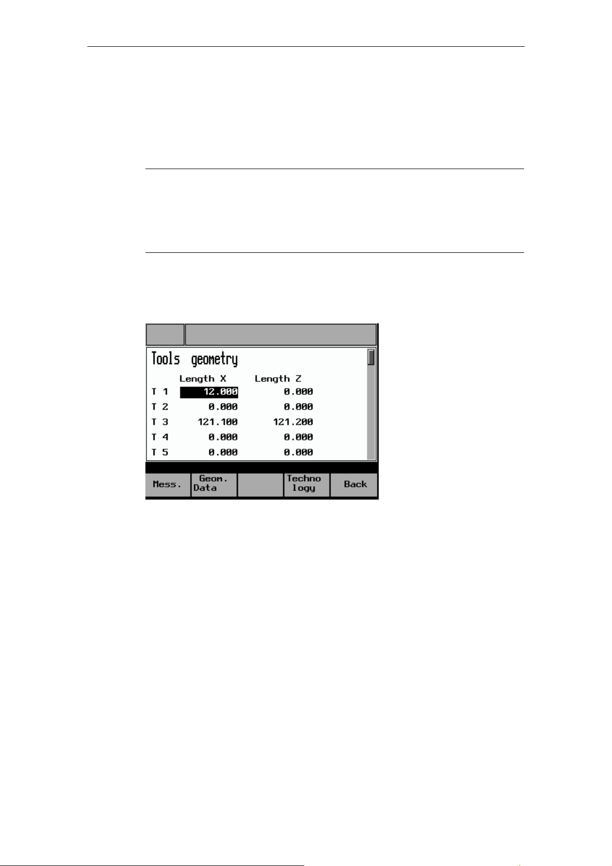
Press the "Geom. data" function key in the "Tool Data Overview" screen form to
open the following screen form for turning tools:
© Siemens AG, 2005. All rights reserved
3-32 SINUMERIK 802S/802C BA_MM (BA) – 04/2005 Edition
Page 33

04/2005 3 Tool Data
3.4 Entering tool technology data
Fig. 3-3: Geometry tool data (turning tools)
The displays for "Length 1" always relate to the X axis, those for "Length 2" to the Z
axis.
If the geometry tool data for a drilling tool is invoked, the following screen form
appears. The use and meaning of the values displayed are the same as those
shown in the “Geometry Tool Data” screen form for turning tools, except that some
of the values are not available for drilling tools.
Fig. 3-4: Geometry tool data (drilling tools)
3.4 Entering tool technology data
This function allows the machine operator to store the cutting technology data for a
tool, known as the tool technology data, together with the tool offset. The
advantage of this function is that when the tool is selected in "Manual Machining",
the machining technology data does not have to be changed; it can simply be
copied from the tool technology data memory. The decision lies with the machine
operator.
© Siemens AG, 2005. All rights reserved
SINUMERIK 802S/802C BA_MM (BA) – 04/2005 Edition
3-33
Page 34

3 Tool Data 04/2005
3.4 Entering tool technology data
Press the "Technology" function key in the "Tool Data Overview" screen form to
open the following screen form:
Fig. 3-5: Tool technology
The following data can be entered in the “Tool Technology” screen form:
Spindle
value
Depending on which operating mode is selected (see below), you
can enter either the spindle speed in "Rev/min" or the cutting rate
in "m/min".
Feed value Depending on which operating mode is selected (see below) this
parameter requires the desired axis speed to be entered in either
"mm/min" or "mm/Rev".
Inactive "Inactiv" indicates that no tool technology data has been entered
yet for the corresponding tool.
The tool technology data should be entered as follows:
• Use the cursor keys to select an entry field for the tool in question (spindle or
feedrate entry field is irrelevant).
• To select the desired machining mode, press the "Spindle Feed" function key
one or more times:
(for a more detailed description: → Entering machining technology data)
• "Spindle speed + Time feed" ("Rev/min" + "mm/min") →
"Spindle speed + Rev. feedrate" ("Rev/min" + "mm/Rev") →
"Cutting speed + Rev. feedrate" ("m/min" + "mm/U")
• Use the numeric keypad to enter data in the entry fields for the spindle and
feedrate value. Then press Enter to accept the data. If you leave the entry field
or change the screen form without pressing Enter, the original value will be
retained (the new value is not saved).
© Siemens AG, 2005. All rights reserved
3-34 SINUMERIK 802S/802C BA_MM (BA) – 04/2005 Edition
Page 35

04/2005 3 Tool Data
3.5 Deleting tool technology data
3.5 Deleting tool technology data
Data in the "Tools Technology" screen form can be deleted as follows:
• Use the cursor keys to select an entry field for the tool in question (spindle or
feedrate entry field is irrelevant).
• Press the "Cancel Techno" function key
The following prompt appears:
Fig. 3-6: Deleting tool technology
The question can be answered by pressing one of these function keys:
"OK" The tool technology data for the tool in question is deleted (spindle
and feedrate value) and the system returns automatically to the
"Tools Technology" screen form. The display "Inactive" indicates
that the spindle and feedrate values have been deleted.
"Abort" The tool technology data for the tool in question is retained (spindle
and feedrate value) and the system returns automatically to the
"Tools Technology" screen form. The existing tool technology data
is retained.
© Siemens AG, 2005. All rights reserved
SINUMERIK 802S/802C BA_MM (BA) – 04/2005 Edition
3-35
Page 36

3 Tool Data 04/2005
3.5 Deleting tool technology data
© Siemens AG, 2005. All rights reserved
3-36 SINUMERIK 802S/802C BA_MM (BA) – 04/2005 Edition
Page 37

04/2005 4 Functions
4.1 Limit stops
4
4 Functions
4.1 Limit stops..................................................................................... 4-38
4.1.1 Setting limit stops....................................................................... 4-38
4.1.2 Activating/disabling limit stops ................................................... 4-40
4.1.3 Turning against mechanical stoppage....................................... 4-41
4.2 Taper turning................................................................................. 4-42
4.3 Radius turning............................................................................... 4-44
4.4 Drilling - centered.......................................................................... 4-46
4.5 Tapping ......................................................................................... 4-49
4.6 Groove cycles/Parting................................................................... 4-53
4.6.1 Groove cycle - single ................................................................. 4-53
4.6.2 Groove cycle - multiple .............................................................. 4-57
4.6.3 Parting........................................................................................ 4-59
4.6.4 Multiple parting .......................................................................... 4-60
4.7 Thread cutting.............................................................................. 4-61
4.7.1 Longitudinal thread cutting......................................................... 4-61
4.7.2 Thread recutting......................................................................... 4-65
4.7.3 Thread shaving after thread cutting........................................... 4-67
4.8 Cutting cycles................................................................................ 4-68
4.8.1 Cutting cycle A........................................................................... 4-69
4.8.2 Cutting cycle B........................................................................... 4-73
4.8.3 Cutting cycle C........................................................................... 4-77
4.9 Setting the workpiece zero point................................................... 4-80
© Siemens AG, 2005. All rights reserved
SINUMERIK 802S/C BA_MM (BA) – 04/2005 Edition
4-37
Page 38

4 Functions 04/2005
4.1 Limit stops
4.1 Limit stops
Limit stops are used to stop the axes in a specific position. If an axis stops in the
limit stop position, it cannot be moved again until the triggering limit stop is reset.
This function can be used in "Manual Machining" mode to turn simple steps
(including tapers) without the need for any further cycle parameterization.
→ Turning against mechanical stoppage
Boundary conditions
• The trip position is always an absolute dimension, i.e. it always corresponds to
the position of the absolute actual value display in "Manual Machining". A
relative limit stop position is not possible.
• A limit stop position can only be entered or accepted when the axes are
stationary; otherwise, an error message appears.
4.1.1 Setting limit stops
The screen form for setting trips is opened from the main "Manual Machining"
screen (Fig. 2-4) as follows:
• Change the function key bar by pressing the "Extended menu" key
Fig. 4-1: Extended "Manual Machining“
:
© Siemens AG, 2005. All rights reserved
4-38 SINUMERIK 802S/C BA_MM (BA) – 04/2005 Edition
Page 39

04/2005 4 Functions
4.1 Limit stops
• Press the "Tripping" function key. The following screen form appears:
Fig. 4-2: Setting limit stops
The displays in the "Tripping" screen form have the following meanings:
ON The limit stop shown in this line is switched on, so it is active.
OFF The limit stop shown in this line is switched off, so it is inactive.
-X Negative limit stop for the X axis. If the limit stop is active, the axis
stops automatically when the absolute limit stop position (entered in
this line) is reached by traversing the axis in the negative direction.
+X Positive limit stop for the X axis. If the limit stop is active, the axis
stops automatically when the absolute limit stop position (entered in
this line) is reached by traversing the axis in the positive direction.
-Z Negative limit stop for the Z axis. If the limit stop is active, the axis
stops automatically when the absolute limit stop position (entered in
this line) is reached by traversing the axis in the negative direction.
+Z Positive limit stop for the Z axis. If the limit stop is active, the axis
stops automatically when the absolute limit stop position (entered in
this line) is reached by traversing the axis in the positive direction.
When the screen form appears there are two ways to enter the limit stop position:
• Direct position entry: Use the cursor keys to highlight the entry field for the
appropriate trip. Now use the numeric keypad to enter the absolute position you
require. Then press Enter to accept the value. If you do not wish to accept the
value entered, either leave the entry field by pressing the cursor key or change
the screen form by pressing the "Back" function key, without pressing Enter. In
both cases the original entry value is retained.
© Siemens AG, 2005. All rights reserved
SINUMERIK 802S/C BA_MM (BA) – 04/2005 Edition
4-39
Page 40

4 Functions 04/2005
4.1 Limit stops
• Accepting the current actual position: Use the cursor keys to highlight the entry
field for the appropriate trip. Now press Enter to copy the position of the
corresponding axis into the entry field.
!
!
Note
A limit stop position can only be entered or accepted when the axes are
stationary; otherwise, an error message appears.
Note
The trip position is always an absolute dimension, i.e. it always corresponds to
the position of the absolute actual value display in "Manual Machining". A relative
limit stop position is not possible.
4.1.2 Activating/disabling limit stops
Trips can be activated or disabled by means of the function keys in the "Tripping"
screen form, provided that all axes are stationary when the function key is pressed.
Otherwise, an error message appears.
The function keys have the following functions:
"Single ONOFF"
Pressing this function key activates or disables the limit stop
whose entry field is highlighted. Use the cursor keys to select the
appropriate entry field. If a trip is shown as "OFF" in the display,
it can be activated by pressing the "Single ON-OFF" function
key. It will then be shown as "ON" in the display. It can be
disabled in the same way: If a trip is shown as "ON", pressing the
function key changes it to "OFF". It is now disabled.
"All ON" Pressing the "All ON" function key activates all trips, regardless
of their previous status. The display is then set to "ON" for all
trips.
"All OFF" Pressing the "All OFF" function key disables all trips, regardless
of their previous status. The display is then set to "OFF" for all
trips.
© Siemens AG, 2005. All rights reserved
4-40 SINUMERIK 802S/C BA_MM (BA) – 04/2005 Edition
Page 41

04/2005 4 Functions
4.1 Limit stops
4.1.3 Turning against mechanical stoppage
The example below is intended to clarify how the limit stops work. Machining can
generally also be carried out using the handwheel (rather than the 4-way switch or
axis direction keys as described here):
A step of 100 mm in the Z direction and a 50 mm end diameter in the X direction is
required, with a final machining allowance of 0.2 mm. The blank diameter is 70 mm
and the end face is at 0 mm in the Z direction (→ Tool calibration).
• Position the axes in front of the workpiece (e.g., X +75 mm/Z +5 mm).
• Check the machining technology data.
• Set the limit stops: -X at 50.4 mm/-Z at –99.8 mm (because of the final
machining allowance), +Z at +5 mm. Disable the limit stop for +X; it is not
required.
• Start spindle.
st
• Using the handwheel, infeed to the 1
depth of cut in the X direction.
• Start machining in the Z axis in the negative direction, using the 4-way switch or
the axis direction key.
• When the -Z trip position at –99.8 mm is reached, the Z axis stops automatically
and the "-Z trip reached" message appears.
• Switch off the 4-way switch or the axis direction key.
• Retract with the handwheel.
• Using the 4-way switch or axis direction key and rapid traverse overlay, traverse
in front of the workpiece in the positive Z direction until the axis stops and the
"+Z trip reached" message appears.
• Switch off the 4-way switch or the axis direction key.
• Using the handwheel, infeed to the next depth of cut in the X direction.
• Start machining in the Z axis in the negative direction, using the 4-way switch or
the axis direction key.
Repeat the process until the roughing depth is reached (the "-X trip reached"
message appears as the infeed motion is executed). Once this cut has been
completed, adjust the limit stops to the finished dimension, provided that the axes
are ahead of the workpiece.
• Set the stops to the finished dimension: -X to 50.0 mm/-Z to –100.0 mm
• Using the handwheel, infeed in the X direction until the "-X trip reached"
message appears.
© Siemens AG, 2005. All rights reserved
SINUMERIK 802S/C BA_MM (BA) – 04/2005 Edition
4-41
Page 42

4 Functions 04/2005
4.2 Taper turning
• Start machining in the Z axis in the negative direction, using the 4-way switch or
the axis direction key.
• When the -Z trip position at –100,.0 mm is reached, the Z axis stops
automatically and the "-Z trip reached" message appears.
• Switch off the 4-way switch or the Z direction axis direction key and start in the
positive X direction (finishing the end face).
• Switch off the 4-way switch or the X direction axis direction key as soon as the
tool tip leaves the workpiece.
• Machining is now complete and the limit stops can be disabled again.
4.2 Taper turning
The Taper turning function is intended for the simple production of tapered
workpieces. The procedure is basically the same as for "Manual Machining" apart
from the addition of an angle (angle of taper). The angle input rotates the
controller’s internal coordinate system according to the angle value. When the 4way switch or an axis direction key is actuated, the controller then uses the angle
input to interpolate (and traverse) the X and Z axis accordingly.
The programmed axis feed then applies to the path being traversed and not to the
corresponding axis.
If tapers with defined end points are to be turned, the use of limit stops is a helpful
addition to this function. Limit stops
!
!
Note
A taper can only be traversed using the 4-way switch or the axis direction keys.
Handwheel traversing is always a paraxial traverse and will not produce a taper.
Note
Taper turning can only be selected when the spindle is running; otherwise, an
error message appears.
The Taper turning function is accessed from the main "Manual Machining" screen
(Fig. 2-4) as follows:
• Change the function key bar by pressing the "Extended menu" key
.
© Siemens AG, 2005. All rights reserved
4-42 SINUMERIK 802S/C BA_MM (BA) – 04/2005 Edition
Page 43

04/2005 4 Functions
4.2 Taper turning
• Press the "Taper turn" function key. The following screen form appears:
Fig. 4-3: Taper turning
As soon as the screen form appears, the entry field for the angle of taper is
highlighted to enable the angle to be entered using the numeric keypad. A positive
angle rotates the coordinate system towards the spindle when viewed in the X+
traverse direction, a negative angle rotates it towards the tailstock. Press Enter to
accept the value. The taper angle remains active until the "Taper Turning" screen
form is closed by pressing the "End Taper" function key.
The diagrams below show the relationship between the sign of the angle and the
rotation of the coordinate system.
Positive angle:
Fig. 4-4: Rotation of coordinates with a positive angle
Negative angle:
Fig. 4-5: Rotation of coordinates with a negative angle
© Siemens AG, 2005. All rights reserved
SINUMERIK 802S/C BA_MM (BA) – 04/2005 Edition
4-43
Page 44

4 Functions 04/2005
4.3 Radius turning
4.3 Radius turning
The radius turning function is intended for the simple production of inside and
outside radii. All the technology data needed for the machining operation is
automatically taken from "Manual Machining". The positions of the axes at the time
the NC start key is pressed form the starting point for the radii to be traversed.
!
!
Note
The required radius is executed by pressing NC start and can be interrupted at
any time by pressing NC stop.
The 4-way switch or the axis direction keys and the handwheels are always disabled when
using this function.
Note
Radius turning can only be selected when the spindle is running; otherwise, an
error message appears.
The Taper turning function is accessed from the main "Manual Machining" screen
(Fig. 2-4) as follows:
• Change the function key bar by pressing the "Extended menu" key
• Press the "Radius turn" function key. The following screen form appears:
.
Fig. 4-6: Radius turning
© Siemens AG, 2005. All rights reserved
4-44 SINUMERIK 802S/C BA_MM (BA) – 04/2005 Edition
Page 45

04/2005 4 Functions
4.3 Radius turning
The entry fields have the following meanings:
This entry value describes the position of the circle end position in the X
x1
axis. The value should be the "relative linear measurement" (in the radius)
whose starting point is the circle start position (= current X axis position in
the diameter).
This entry value describes the position of the circle end position in the Z
z1
axis. The value should be the "relative linear measurement" whose starting
point is the circle start position (= current Z axis position).
This entry value describes the radius to be traversed.
r
The function key assignments are as follows:
Arc
Direct.
This key is used to specify whether a clockwise or counterclockwise
circle should be traversed. The chosen direction is indicated by a
diagram in the screen form.
Abort This key can be used to abort a non-executable radius machining
operation without having to leave the "Radius turning" screen form.
The relevant entry value can then be corrected. For the operation to
be aborted successfully, the only requirement is that the spindle
must have been switched off before the function key is pressed. If
not, a corresponding message will appear and the function will be
disabled.
Caution
Omitting or using the wrong sign for the entry values (x1, z1) or entering the
wrong arc direction ("Arc Direct." function key) can lead to a collision and may
destroy the tool or the workpiece.
Once all the entry values have been entered correctly, radius turning can be
started by pressing the NC start key. Since the starting point for the radius is
always the current axis position, a kind of "surface texture" can be achieved by
pressing the NC start key repeatedly.
Any radius execution can be interrupted immediately by pressing the NC stop key.
Execution can only be continued by pressing the NC Start key before exiting the
"Radius turning" screen form, since exiting the screen form terminates the function.
If the screen form is opened again, the system assumes that you wish to execute a
new radius starting from the current axis position (in this case, the point of
interruption) and calculates it accordingly. An interrupted radius will not be
completed.
© Siemens AG, 2005. All rights reserved
SINUMERIK 802S/C BA_MM (BA) – 04/2005 Edition
4-45
Page 46

4 Functions 04/2005
4.4 Drilling - centered
Note
Any limit stops that are activated should be disabled before starting radius turning
or set to a value outside the traversing range needed for radius turning.
Otherwise an error message is transmitted by the controller which prevents the
"Radius turning" function being started.
→ Setting limit stops
4.4 Drilling - centered
The "Drilling" function is designed to produce deep-hole drill holes in the vicinity of
the turning center. Before the start of the cycle, the tool should be positioned in the
turning center so that the hole can be machined by infeeding in the longitudinal
axis only.
The technology data needed for the machining operation is automatically taken
from the entry fields in "Manual Machining".
!
Note
"Drilling" can only be selected when the spindle is running, otherwise an error
message appears.
Caution
In drilling operations, a spindle rotating in the wrong direction can cause serious
damage to the tool, workpiece or machine!
→ Check the direction of rotation of the spindle before pressing NC start!
Caution
Before starting the drilling operation, ensure that the tool is correctly positioned in
the turning center; otherwise, the drilling tool or workpiece may be damaged!!
→ Check that the tool is in the turning center before pressing NC start!!
The "Drilling - centered" function is accessed from the main "Manual Machining"
screen (Fig. 2-4) as follows:
• Change the function key bar by pressing the "Extended menu" key
.
© Siemens AG, 2005. All rights reserved
4-46 SINUMERIK 802S/C BA_MM (BA) – 04/2005 Edition
Page 47

04/2005 4 Functions
4.4 Drilling - centered
• Press the "Drilling" function key. The following screen form appears:
Fig. 4-7: Drilling - centered
The entry fields have the following meanings:
Bezug z0 Start position for the drill hole in the longitudinal axis
(absolute position of the Z axis).
Tiefe l Enter the depth of the drill hole to be created, taking the start
position for the drill hole ("Refer. z0") as the starting point.
The drilling direction is always towards the chuck and cannot
be reversed.
Zust. Max Maximum infeed value for the 1
st
infeed in the longitudinal
axis.
Min Minimum infeed value in the longitudinal axis, which must be
observed for the final infeed.
Faktor Degression factor: the value by which the 2
nd
and all
subsequent infeeds in the longitudinal axis must be
multiplied. The following general rule applies: an entry value
greater than 1 increases the infeed depth with each infeed,
an entry value of less than 1 reduces it with each infeed. To
switch off degression, enter 1 (or 0) here.
Zeit t Dwell time on reaching the drilling depth.
Rückhub R Length of the return stroke in the longitudinal axis for chip
breaking. This parameter is not displayed if "deswarfing" is
selected.
© Siemens AG, 2005. All rights reserved
SINUMERIK 802S/C BA_MM (BA) – 04/2005 Edition
4-47
Page 48

4 Functions 04/2005
4.4 Drilling - centered
Meaning of the function keys:
"Spanbr./
Entsp"
This key is used to toggle between machining with "swarf
breaking" and with "deswarfing". With "swarf breaking", on
reaching the corresponding infeed depth the tool is retracted in
the axial axis by a defined value (swarf breaking) before the
next infeed. With "deswarfing" on the other hand, the tool is
withdrawn from the drill hole on reaching the corresponding
infeed depth. The next infeed then continues as usual. The
current selection is shown as a graphic in the left-hand section
of the screen. If "deswarfing" is selected, no value is shown for
the "return".
"Achspos
übern.”
The current actual position of the relevant axis can be accepted
by selecting an input parameter (entry field is highlighted) and
pressing this function key. If you try to accept the axis position
in entry fields for which this type of value input is not viable,
however, an error message appears, which must be
acknowledged by pressing the function key.
"Ausführen" This function key opens the screen form in which the actual
machining operation takes place:
Fig. 4-8: Execute drilling
Once all the entry values have been entered correctly and the screen form shown
above has been opened, drilling can be started by pressing the NC start key. The
spindle must already be rotating in the correct direction and the drilling tool
positioned in the turning center.
Machining proceeds as follows:
• Starting from the current axis position, the tool is traversed to the cycle start
point in the longitudinal axis. This is calculated internally from the value for the
"Referenc z0" parameter (taking into account the clearance distance).
© Siemens AG, 2005. All rights reserved
4-48 SINUMERIK 802S/C BA_MM (BA) – 04/2005 Edition
Page 49

04/2005 4 Functions
4.5 Tapping
• The first infeed in the axial axis (as defined in the "Infeed Max." parameter) is
then performed.
• The subsequent traversing movement in the axial axis depends on whether
"swarf breaking" or "deswarfing" has been selected. With "swarf breaking" the
tool is retracted in the axial axis by the value set in the "return" parameter; with
"deswarfing" the axial axis is positioned at the cycle start point.
• The subsequent infeeds in the longitudinal axis are always calculated in the
same way: new infeed value = last infeed value x factor + return stroke value
The new infeed value is monitored to ensure that it complies with the value for
the "Infeed Min." parameter. If the infeed value is below the minimum infeed,
this value is imposed, provided that the drilling depth allows it. The calculation is
followed by the infeed in the longitudinal axis.
• Infeed motion and "swarf breaking/deswarfing" then alternate until the drilling
depth specified in the "Length I" parameter is reached.
• Once the required drilling depth is reached, the waiting time specified in the
"Dwell t" parameter begins.
• At the end of this waiting time, the tool is traversed to the cycle start point in the
longitudinal axis.
Machining is now complete and once the spindle has been switched off the
"Execution" screen form can be closed by pressing the "Cycle finish" function key.
4.5 Tapping
The "Tapping" function is designed to produce internal threads in the vicinity of the
turning center using a compensating chuck.
Before the start of the cycle, the tool should be positioned in the turning center so
that the hole can be machined by infeeding in the longitudinal axis only.
The technology data needed for the machining operation is automatically taken or
calculated from the entry fields in "Manual Machining", as follows:
Spindle
speed
The cycle takes the spindle speed setting directly from the entry
field for "Const. spind. speed".
→ Entering machining technology data
© Siemens AG, 2005. All rights reserved
SINUMERIK 802S/C BA_MM (BA) – 04/2005 Edition
4-49
Page 50

4 Functions 04/2005
4.5 Tapping
Pitch The pitch is formed as follows according to the option selected in
the "Machining Technology Data" screen form:
- "Spindle speed + Time feed":
In this case, the pitch (mm/rev) is calculated as follows from the
entry value for the Time feed (mm/min) and the current spindle
speed (rev/min):
The calculation is made when the NC start key is pressed in the
“Execution” screen form for tapping. Since the actual speed
forms part of the calculation, it is essential that the spindle
override valuation is already set to "100%" at this point.
Otherwise, a defined pitch cannot be set.
- "Spindle speed + Rev. feedrate":
Here the pitch is taken directly from the "Rev. feedrate" value
(mm/Rev) in the Machining Technology Data screen form.
- "Cutting speed + Rev. feedrate":
Here the pitch is taken directly from the "Rev. feedrate" value
(mm/Rev) in the Machining Technology Data screen form.
!
Note
"Tapping" can only be selected when the spindle is running, otherwise an error
message appears.
Caution
In tapping operations, a spindle rotating in the wrong direction can cause serious
damage to the tool, workpiece or machine.
→ Check the direction of rotation of the spindle before pressing NC start.
Caution
Before starting the tapping operation, ensure that the tool is correctly positioned
in the turning center; otherwise, the tapping tool or workpiece may be damaged.
→ Check that the tool is in the turning center before pressing NC start.
© Siemens AG, 2005. All rights reserved
4-50 SINUMERIK 802S/C BA_MM (BA) – 04/2005 Edition
Page 51

04/2005 4 Functions
4.5 Tapping
Caution
If "Time feed" is selected in the “Machining Technology Data” screen form, in
order for the pitch to be calculated correctly, the spindle override valuation must
be set to "100%". Otherwise, the tapping tool or workpiece may be damaged.
Prior to NC start, check that the spindle override valuation is set to 100%!!
The “Tapping” function is accessed from the main "Manual Machining" screen
(Fig. 2-4) as follows:
• Change the function key bar by pressing the "Extended menu" key
.
• Press the "Gewindebohren" function key. The following screen form appears:
Fig. 4-9: Tapping
The entry fields have the following meanings:
Bezug z0 Start position for the drill hole in the longitudinal axis
(absolute position of the Z axis).
Tiefe l Enter the thread length here. The tapping direction is always
towards the chuck and cannot be reversed. The choice of
"left-hand or right-hand thread" depends on the direction of
rotation of the spindle and the thread tapping tool.
"Achspos
übern."
The current actual position of the axial axis can be accepted
by selecting the input parameter "Referenc z0" (entry field is
highlighted) and pressing this function key. If you try to accept
the axis position in the "Length I" entry field, however, an
error message appears which must be acknowledged by
pressing the function key.
© Siemens AG, 2005. All rights reserved
SINUMERIK 802S/C BA_MM (BA) – 04/2005 Edition
4-51
Page 52

4 Functions 04/2005
4.5 Tapping
"Ausführen"
Fig. 4-10: Execute tapping
This function key opens the screen form in which the actual
machining operation takes place:
Once all the entry values have been entered correctly and the screen form shown
above has been opened, machining can be started by pressing the NC start key.
The spindle must already be rotating in the correct direction and the tapping tool
positioned in the turning center.
Machining proceeds as follows:
• Starting from the current axis position, the tool is traversed to the cycle start
point in the longitudinal axis. This is calculated internally from the value for the
"Referenc z0" parameter (taking into account the clearance distance).
• The controller then waits (at the cycle start point) for the next marker pulse from
the spindle encoder in order to start the axis movement in the longitudinal axis
(defined thread start point).
• When the thread length (end point) is reached, the spindle and longitudinal axis
change direction and withdraw the tapping tool from the drill hole again.
• The longitudinal axis then stops at the cycle start point and the spindle changes
direction again. The spindle is now running in the direction in which it was
originally started.
Machining is now complete and once the spindle has been switched off the
"Execution" screen form can be closed by pressing the "Zyklus ENDE" function key.
© Siemens AG, 2005. All rights reserved
4-52 SINUMERIK 802S/C BA_MM (BA) – 04/2005 Edition
Page 53

04/2005 4 Functions
4.6 Groove cycles/parting
4.6 Groove cycles/parting
The "Groove cycles" function is suitable for producing symmetrical grooves on the
lateral surface and for parting turned parts. Groove cycles can be used to produce
filleted corners or beveled edges (45° chamfer) on the lateral surface.
In addition, the "Multiple execution" function can be used to produce multiple
partings and multiple grooves with a uniform offset.
The technology data needed for the machining operation is automatically taken
from the entry fields in "Manual Machining".
!
Note
"Groove cycles" and "Parting" can only be selected when the spindle is running,
otherwise an error message appears.
Caution
In machining operations, a spindle rotating in the wrong direction can cause
serious damage to the tool, workpiece or machine!!
→ Check the direction of rotation of the spindle before pressing NC start!!
4.6.1 Groove cycle - single
The "Groove cycle - single" function is accessed from the main "Manual Machining"
screen (Fig. 2) as follows:
• Change the function key bar by pressing the "Extended menu" key
• Press the “Cycles” function key to call the main Cycle Selection screen.
• Press the "Grooving" function key. The following screen form appears:
twice.
Fig. 4-11: Groove cycle - single
© Siemens AG, 2005. All rights reserved
SINUMERIK 802S/C BA_MM (BA) – 04/2005 Edition
4-53
Page 54

4 Functions 04/2005
4.6 Groove cycles/parting
The entry fields have the following meanings:
Bezug z0 Starting position for the groove. The edge of the groove
facing the spindle chuck is always specified here. The value
to be entered is the absolute position in the longitudinal axis
(Z axis).
Länge l1 This value is the groove width, which together with the value
for "Referenc z0" specifies the absolute position of the edge
of the groove on the side of the groove facing away from the
spindle. If the groove width setting is the same as the tool
width ("Length l2") and "0" is assigned to the parameters
"Edge R/C1" and "Edge R/C2", the parting function is
activated.
l2 Width of the grooving tool. The cycle needs this information to
calculate the individual groove positions for the grooving
operation.
Durch-m.d Starting diameter for the groove. The value to be entered is
the absolute position in the transverse axis (X axis).
Tiefe t This value is the groove depth which together with the value
for "Diameter d" specifies the absolute position of the base of
the groove.
Kante F/R1 Depending on the option selected, this value forms either a
leading radius (display "R1") or a leading chamfer (display
"C1") of less than 45° on both sides of the groove. Press the
function key to toggle between radius and chamfer. An entry
value of 0.0 switches this function off.
F/R2 Depending on the option selected, this value forms either a
radius (display "R2") or a chamfer (display "F2") of less than
45° on both sides of the groove as the transition to the base
of the groove. Press the function key to toggle between radius
and chamfer. An entry value of 0.0 switches this function off.
v m1 Enter the maximum infeed depth for roughing during
grooving. The cycle’s internal infeed calculation ensures that
this entry value is not exceeded during machining.
vvv m2 Final machining allowance perpendicular to the contour.
© Siemens AG, 2005. All rights reserved
4-54 SINUMERIK 802S/C BA_MM (BA) – 04/2005 Edition
Page 55

04/2005 4 Functions
4.6 Groove cycles/parting
Meaning of the function keys:
"Radien/Fasen" This function key is used to select whether the value in the
"Kanten" entry fields (R/C1, R/C2) should be interpreted as
a chamfer length or a radius. The setting only applies to the
entry field selected at the time the function key is pressed
(entry field is highlighted). The selection is shown next to
the corresponding field.
"Achspos übern." The current actual position of the corresponding axis can be
accepted by selecting an input parameter (entry field is
highlighted) and pressing this function key. If you try to
accept the axis position in entry fields for which this type of
value input is not viable, however, an error message
appears, which must be acknowledged by pressing the
function key.
"Ausführen" This function key opens the screen form in which the actual
machining operation takes place:
Fig. 4-12: Execute grooving cycle
Once all the entry values have been entered correctly and the screen form shown
above has been opened, machining can be started by pressing the NC start key.
The spindle must already be rotating in the correct direction and the axes must be
in a position from which the groove can be approached without the risk of a
collision.
© Siemens AG, 2005. All rights reserved
SINUMERIK 802S/C BA_MM (BA) – 04/2005 Edition
4-55
Page 56

4 Functions 04/2005
4.6 Groove cycles/parting
Machining proceeds as follows:
• Starting from the current axis position, the first calculated groove position is
approached (diagonally) in both axes, taking into account the clearance
distance and final machining allowance.
• Execute the depth infeeds as a roughing motion in the transverse axis (X axis):
each infeed depth is calculated internally so that firstly the setting "m1" is not
exceeded and secondly the infeed distance is kept uniform until the base of the
groove is reached (taking into account the final machining allowance). After
each infeed, the tool is retracted by the clearance distance for chip breaking.
• When the base of the groove is reached for the first time, the tool is withdrawn
from the material at the programmed feedrate.
• This is followed by the width infeed in the longitudinal axis: the width offset is
calculated internally, taking into account the tool width (length "l2") and the
groove width (length "l1") so that the machining is as uniform as possible.
• Depth infeeds are then alternated as roughing motion and width offset until the
entire groove contour has been cleared. The only difference between the first
depth infeed and the others is that when the base of the groove is reached, the
tool is retracted by the clearance distance and then moved out of the groove in
rapid traverse.
• Finishing is started immediately after the roughing operation. The entire contour
is covered from both sides to the center of the base of the groove at the
feedrate specified in the “Technology Data” screen form before the start of the
cycle.
• Finally, the original position of the axes before the start of machining is
approached diagonally.
Machining is now complete and once the spindle has been switched off the
"Execution" screen form can be closed by pressing the "Zyklus ENDE" function
key.
© Siemens AG, 2005. All rights reserved
4-56 SINUMERIK 802S/C BA_MM (BA) – 04/2005 Edition
Page 57

04/2005 4 Functions
4.6 Groove cycles/parting
4.6.2 Groove cycle - multiple
Note
Since the "Groove cycle - multiple" function is an addition to "Groove cycle single", the "Groove cycle - single" function must first be parameterized in full!
→ Groove cycle - single
The "Groove cycle - single" function is accessed from the main "Manual Machining"
screen (Fig. 4-13) as follows:
• Change the function key bar by pressing the "Extended menu" key
; the
following screen form appears:
Fig. 4-13: Groove cycle - multiple
The entry fields have the following meanings:
Länge l3 Groove offset in the longitudinal axis (Z axis): the value entered
here determines the offset between several identical grooves
during production. The direction of the groove offset between the
individual grooves is always towards the chuck.
Anzahl
n Number of grooves to be produced. Entering "0" or "1" here has
the same effect: a single groove is produced. If a value greater
than 1 is entered, the corresponding number of grooves is
produced and the necessary offset is formed by the value
entered for the "Length l3" parameter.
© Siemens AG, 2005. All rights reserved
SINUMERIK 802S/C BA_MM (BA) – 04/2005 Edition
4-57
Page 58

4 Functions 04/2005
4.6 Groove cycles/parting
Caution
In Groove cycle - multiple, ensure that the distance from the starting point
"Reference z0" to the spindle is sufficient to enable all parameterized grooves to
be produced; otherwise, a collision may occur between the tool and the spindle
chuck!
→ Check the viability of the entry values before pressing NC start!
Meaning of the function key:
"Ausführen" This function key opens the screen form in which the actual
machining of multiple grooves takes place:
Fig. 4-14: Execute Groove cycle - multiple
Once all the entry values have been entered correctly and the screen form shown
above has been opened, machining can be started by pressing the NC start key.
The spindle must already be rotating in the correct direction and the axes must be
in a position from which the grooves can be approached without the risk of a
collision.
Machining proceeds as follows:
• Starting from the current axis position, the first groove is produced as described
under "Groove cycle - single".
• The starting point for the next groove is then approached in the longitudinal axis
(X axis), taking into account the clearance distance. The offset is always in the
direction of the spindle (chuck).
• Another complete groove is then machined (as described under "Groove cycle -
single").
• Groove machining and offset in the axial axis then alternate until the number of
grooves specified in the "Number n" parameter has been produced.
© Siemens AG, 2005. All rights reserved
4-58 SINUMERIK 802S/C BA_MM (BA) – 04/2005 Edition
Page 59

04/2005 4 Functions
4.6 Groove cycles/parting
• On completion of the final groove, the original position of the axes before the
start of machining is approached diagonally.
Machining of the multiple grooves is now complete and once the spindle has been
switched off the "Execution" screen form can be closed by pressing the "Zyklus
ENDE" function key.
4.6.3 Parting
The "Parting" function is a subfunction of the "Groove cycle - single" function
(→ "Groove cycle - single"), the difference being that specific settings for some of
the input parameters change the machining cycle:
• Parameter "Length l1" = "Length l2" (= activate "parting")
• Parameter "Edges R/F1" = 0
• Parameter "Edges R/C2" = 0.0
Setting the groove width and the tool width to the same value activates the
"parting" function. The radius/chamfer parameters must be set to "0", otherwise the
cycle cannot calculate the contour and displays an error message ("Groove form
not defined correctly").
Once all values have been entered correctly and the "Execution" screen form has
been opened, machining can be started as described in "Groove cycle - single"
(→ "Groove cycle - single") by pressing the NC Start key.
The spindle must already be rotating in the correct direction and the axes must be
in a position from which the cut-off can be approached without the risk of a
collision.
Machining proceeds as follows:
• Starting from the current axis position, the first calculated parting position is
approached (diagonally) in both axes, taking into account the clearance
distance.
• Execute the depth infeeds as a roughing motion in the transverse axis (X axis):
each infeed depth is calculated internally so that firstly the setting "m1" is not
exceeded and secondly the infeed distance is kept uniform until the base of the
groove (parting depth) is reached. After each infeed, the tool is retracted by the
clearance distance for chip breaking.
• When the base of the groove is reached, the tool is withdrawn from the material
at the programmed feedrate.
• Finally, the original position of the axes before the start of machining is
approached diagonally.
Machining is now complete and once the spindle has been switched off the
"Execution" screen form can be closed by pressing the "Cycle finish" function key.
© Siemens AG, 2005. All rights reserved
SINUMERIK 802S/C BA_MM (BA) – 04/2005 Edition
4-59
Page 60

4 Functions 04/2005
4.6 Groove cycles/parting
4.6.4 Multiple parting
The "Multiple parting" function is a subfunction of the "Groove cycle - multiple"
function (→ "Groove cycle - multiple"), the difference being that specific settings for
some of the input parameters change the machining cycle:
• Parameter "Length l1" = "Length l2" (= activate "parting")
• Parameter "Edges R/F1" = 0
• Parameter "Edges R/C2" = 0.0
Setting the groove width and the tool width to the same value activates the
"parting" function. The radius/chamfer parameters must be set to "0", otherwise the
cycle cannot calculate the contour and displays an error message ("Groove form
not defined correctly").
Once all values have been entered correctly and the "Execution" screen form has
been opened, machining can be started as described in "Groove cycle - multiple"
(→ "Groove cycle - multiple") by pressing the NC Start key.
The spindle must already be rotating in the correct direction and the axes must be
in a position from which the cut-offs can be approached without the risk of a
collision.
Caution
In multiple parting, ensure that the distance from the starting point "Reference z0"
to the spindle is sufficient to enable all parameterized parting motions to be
completed; otherwise, a collision may occur between the tool and the spindle
chuck.
→ Check the viability of the entry values before pressing NC start.
Machining proceeds as follows:
• Machining takes place in the same way as for machining of "multiple grooves"
(→ Groove cycle - multiple). The only difference lies in the fact that this is a
"parting" rather than a "grooving" operation (machining cycle → Parting)
Finally, the original position of the axes before the start of machining is approached
diagonally.
Machining is now complete and once the spindle has been switched off the
"Execution" screen form can be closed by pressing the "Cycle finish" function key.
© Siemens AG, 2005. All rights reserved
4-60 SINUMERIK 802S/C BA_MM (BA) – 04/2005 Edition
Page 61

04/2005 4 Functions
4.7 Thread cutting
4.7 Thread cutting
The Thread cutting function provides a number of options for producing,
remachining and recutting longitudinal and tapered threads.
They can be single-start or multiple-start threads.
The machining technology data for thread cutting is taken from "Manual
Machining", as is the current tool offset.
Note
Any limit stops that are activated should be disabled before starting thread cutting
or set to a value outside the traversing range needed for thread cutting.
→ Setting limit stops
4.7.1 Longitudinal thread cutting
The “Tapping” function is accessed from the main "Manual Machining" screen
(Fig. 2-4) as follows:
• Change the function key bar by pressing the "Extended menu" key
twice.
• Press the “Cycles” function key to call the main Cycle Selection screen.
• Press the "Thread cutting" function key. The following screen form appears:
Fig. 4-15: Longitudinal thread cutting
As with all other functions, the entry fields are generally selected by means of the
cursor keys, data is entered via the numeric keypad and data accepted by pressing
Enter. If you do not wish to accept a value, either leave the entry field by pressing
a cursor key or change to a different screen form, without pressing Enter.
© Siemens AG, 2005. All rights reserved
SINUMERIK 802S/C BA_MM (BA) – 04/2005 Edition
4-61
Page 62

4 Functions 04/2005
4.7 Thread cutting
The entry fields have the following meanings:
Bezug z0 Start position for the thread in the longitudinal axis (absolute
position of the Z axis).
Länge l Enter the length of the thread to be created, taking the start
position for the thread ("Referenc z0") as the starting point. The
thread cutting direction is selected by pressing the "Feed
direction" function key and is indicated in the diagram by
means of an arrow. The choice of whether to produce a lefthand or a right-hand thread depends purely on the starting
direction for the spindle.
Durchm.d1 Start position for the thread in the transverse axis (absolute
position of the X axis in the diameter). This value applies in the
reference point.
d2 End position for the thread in the transverse axis (absolute
position of the X axis in the diameter).
Stei-
s Enter the required pitch in mm/rev.
gung
Tiefe t This parameter is used to set the thread depth. The infeed
direction and infeed depth depend on other parameters ("Intern
Extern." and "Linear Degrees." function keys; "Angle"
parameter).
Winkel w Infeed angle; this specifies the angle of infeed during
machining.
v m1 Enter the maximum infeed depth (perpendicular to the
cylinder/taper) for roughing. The internal infeed calculation
ensures that this entry value is not exceeded during thread
cutting.
vvv m2 Final machining allowance perpendicular to the cylinder/taper.
© Siemens AG, 2005. All rights reserved
4-62 SINUMERIK 802S/C BA_MM (BA) – 04/2005 Edition
Page 63

04/2005 4 Functions
4.7 Thread cutting
Meaning of the function keys:
"Innen / Aussen” This key is used to select whether an internal or an external
thread is required. The selection is indicated by a diagram
on the screen.
"Vorschu richt." This function key is used to select the feed direction. The
current selection is indicated in the diagram by means of an
arrow below the word "Feed". Machining always starts in the
"reference point" of the thread, which is set by means of
parameters "z0" and "d1". By contrast, the end position for
the thread is calculated from the reference point and thread
length, as a function of the "feed direction" on the one hand
and by direct input via parameter "d2" on the other.
"Gangzahl" The number of threads per unit length can be incremented
by pressing this function key. The current value is shown in
the diagram as a number. When the maximum possible
number of threads is reached, the system automatically
reverts to a single-start thread (indicated by 1 in the
diagram).
"Achspos übern." The current actual position of the relevant axis can be
accepted by selecting an input parameter (entry field is
highlighted) and pressing this function key. If you try to
accept the axis position in entry fields for which this type of
value input is not viable, however, an error message
appears, which must be acknowledged by pressing the
function key.
"Ausführen" This function key opens the screen form in which the actual
machining operation takes place.
The following function keys can be accessed by pressing the "Extended menu" key
:
"Linear
Degrees."
This function key is used to switch between "linear infeed" and
"degressive infeed". The current selection is shown in the
diagram in plain text. "Linear infeed" means that roughing always
takes place at a constant depth of cut, and the internal infeed
calculation is designed so that the value for the "max. infeed
depth" (m1) is not exceeded during the entire thread cutting
operation. "Degressive infeed" on the other hand means that the
volume of cut is kept constant throughout the entire thread
cutting operation. In this case too, the value for "max. infeed
depth" (m1) is observed throughout the entire operation.
"Thread
recut."
© Siemens AG, 2005. All rights reserved
SINUMERIK 802S/C BA_MM (BA) – 04/2005 Edition
This function key is used to select remachining or thread
recutting (
→ Thread recutting).
4-63
Page 64

4 Functions 04/2005
4.7 Thread cutting
Once all the values have been entered correctly, press the "Ausführen" function
key to open the Machining screen form. The following screen form appears:
Fig. 4-16: Execute a thread
Thread cutting can now be started by pressing the NC start key. The spindle must
already be rotating in the correct direction.
Machining proceeds as follows:
• Starting from the current axis position, the start position for the thread (d1/z0) is
approached in rapid traverse.
• This is followed by infeed by the first depth of cut.
• The controller then waits for the next marker pulse from the spindle encoder in
order to start the axis movements (longitudinal axis and/or transverse axis)
(depending on the thread geometry).
• Once the end position for the thread has been reached in both axes, the tool is
withdrawn from the workpiece in rapid traverse.
• The start position for the thread is then approached in the longitudinal and
transverse axis in rapid traverse, observing a clearance distance.
• Infeed to the next depth of cut.
• Wait for the next marker pulse from the spindle encoder to start the axes...
This process continues until all cuts have been completed. An additional finishing
cut is then performed to smooth the thread and once the start position for the
thread in the axial and radial axis has been approached, the "Status Ready"
message appears.
There is now a choice of 2 options:
• If the thread is finished and the spindle has been switched off, press the
"Thread END" function key to close the "Thread END" screen form.
© Siemens AG, 2005. All rights reserved
4-64 SINUMERIK 802S/C BA_MM (BA) – 04/2005 Edition
Page 65

04/2005 4 Functions
4.7 Thread cutting
• If you wish to continue machining the thread, e.g. if thread finishing is required,
press NC Start again.
→ Thread shaving after thread cutting.
4.7.2 Thread recutting
The "Thread recutting" function is a subfunction of "Thread cutting". It can be used
to recut a thread or to continue machining the thread on a workpiece that has been
unclamped in between.
In order for "Thread recutting" to proceed correctly, the appropriate values have to
be entered in the "Thread Cutting" screen form.
→ Thread cutting.
!
Note
The "Thread recutting" function uses the entry values from the "Thread Cutting"
screen form. This screen form must therefore have been completed in order for
thread cutting to proceed correctly.
The "Thread recutting" function is called by pressing the "Thread recut." function
key in the extended "Thread cutting" menu bar.
The following screen form appears:
Fig. 4-17: Thread recutting
The values displayed for start of thread, end of thread and axis position relate to
the longitudinal axis (Z axis). All values displayed on this screen form are for
information only; it is not, therefore, possible to alter them directly.
The actual thread recutting operation must proceed as follows:
• Appropriate values must already have been entered in the "Thread Cutting"
screen form at this point.
• The above screen form appears.
© Siemens AG, 2005. All rights reserved
SINUMERIK 802S/C BA_MM (BA) – 04/2005 Edition
4-65
Page 66

4 Functions 04/2005
4.7 Thread cutting
• The spindle must be stationary (switched off) and must already have been
synchronized, in other words, it must have been turned through at least one full
revolution since the controller was last powered up. Otherwise, an error
message appears when the thread angle is accepted.
• Now use the handwheels to traverse the axes until the thread cutting tool can
be threaded into the existing thread.
• Carefully introduce the tool into the thread. The "Axis position" shown on the
screen must be between the values for "Thread initial p." and "Thread end
point".
• Press the "Teach Angle" function key. The current spindle angle is now
converted into the appropriate starting angle offset for thread cutting. The
starting angle that is now displayed corresponds to the angle that will
subsequently be used as the starting angle offset for machining a right-hand or
left-hand thread.
• Using the handwheels, move the axes into a position from which the start of the
thread can be approached safely.
• Press the "Execution" function key. The following screen form appears:
Fig. 4-18: Execute thread recut
The rest of the thread cutting process is exactly the same as that described for
"Thread cutting".
→ Thread cutting.
The only difference is that thread cutting is not started with the marker pulse from
the spindle encoder but with the angle that was calculated in the previous screen
form (Fig. 4-17) as the "start angle offset".
© Siemens AG, 2005. All rights reserved
4-66 SINUMERIK 802S/C BA_MM (BA) – 04/2005 Edition
Page 67

04/2005 4 Functions
4.7 Thread cutting
4.7.3 Thread shaving after thread cutting
At the end of each thread cutting operation, you can choose to continue machining
the thread, i.e., to perform shaving. Thread shaving can be performed either with or
without an additional infeed, in which case it is merely a "smoothing cut".
To activate the function, simply press the NC Start key again at the end of the
thread when the "Status Ready" message appears.
The following screen form appears:
Fig. 4-19: Thread shaving query
The "With/Without Feed" prompt can be answered using the function keys, which
have the following meanings:
"Without
Feed"
Answering the prompt by pressing this key means that an
additional cut is executed at the same infeed depth as the
previous cut when you press NC start (additional "thread
smoothing").
"With Feed" Answering the prompt by pressing this key means that next time
the NC Start key is pressed, the tool is fed in by the amount
entered in the "Val. f. Feed" field. The thread is machined
accordingly in the next cut.
"Val. f. Feed" This function key is used to enter the infeed value for
subsequent machining. On pressing the key, the corresponding
entry field (already highlighted) is displayed in the screen form
shown below to enable you to enter the value. Press Enter as
usual to accept the value.
© Siemens AG, 2005. All rights reserved
SINUMERIK 802S/C BA_MM (BA) – 04/2005 Edition
4-67
Page 68

4 Functions 04/2005
4.8 Cutting cycles
Fig. 4-20: Enter infeed
After pressing the "With Feed" or "Without Feed" function key, press NC Start to
start machining an additional cut.
If you do not wish to do this, press the "Thread END" function key (with the spindle
switched off) to leave the "Execute Thread" screen form, without pressing NC Start.
4.8 Cutting cycles
The cutting cycles (which are preset in the controller) are the easiest way of
producing common paraxial cutting contours. They are defined by setting particular
input parameters in the appropriate screen forms.
Contour machining can be "internal" or "external", roughing can be "axial" or
"radial" and the machining direction can be "towards the chuck" or "towards the
tailstock".
To facilitate handling, there are three different sets of cycle parameters (contourdependent) available:
• Cutting cycle A:
Simple stepped contour ("step"). Diameter settings and transitions to adjacent
faces can include chamfers or radii.
• Cutting cycle B:
Extended stepped contour with beveling. It is defined by means of 3 Transitions
to adjacent faces can again include chamfers or radii.
• Cutting cycle C:
Extended stepped contour with filleting. It is defined by means of 3 length
settings and one radius setting. Transitions with chamfers or radii are not
possible in this case.
© Siemens AG, 2005. All rights reserved
4-68 SINUMERIK 802S/C BA_MM (BA) – 04/2005 Edition
Page 69

04/2005 4 Functions
4.8 Cutting cycles
The machining technology data and the current tool offset for cutting are taken
from the entry fields in "Manual Machining".
!
Note
"Cutting cycle" can only be selected when the spindle is running, otherwise an
error message appears!
Caution
In machining operations, a spindle rotating in the wrong direction can cause
serious damage to the tool, workpiece or machine!!
→ Check the direction of rotation of the spindle before pressing NC start!
4.8.1 Cutting cycle A
This cyclic function is used to produce a simple stepped contour (step), with the
option of working the transitions to adjacent faces as a radius or chamfer.
The "Cutting cycle A" function is accessed from the main "Manual Machining"
screen (Fig. 2-4) as follows:
• Change the function key bar by pressing the "Extended menu" key twice
• Press the “Cycles” function key to call the main Cycle Selection screen.
• Press the "Cutting cycle A" function key. The following screen form appears:
Fig. 4-21: Cutting cycle A
As with all other functions, the entry fields are generally selected by means of the
cursor keys, data is entered via the numeric keypad and data accepted by pressing
Enter. If you do not wish to accept a value, either leave the entry field by pressing a
cursor key or change to a different screen form, without pressing Enter.
© Siemens AG, 2005. All rights reserved
SINUMERIK 802S/C BA_MM (BA) – 04/2005 Edition
4-69
Page 70

4 Functions 04/2005
4.8 Cutting cycles
The entry fields have the following meanings:
Bezug z0 Contour start position in the longitudinal axis (absolute
position of the Z axis).
Länge l Enter the length of the "step" to be produced, taking the
contour start position ("Referenc z0") in the axial axis (Z
axis) as the starting point.
Durchm. d1 Outside diameter of the "step" to be machined in the radial
axis (absolute position of the X axis in the diameter).
d2 Inside diameter of the "step" to be machined in the radial
axis (absolute position of the X axis in the diameter).
Kante F/R1 Depending on the option selected, this value forms either a
transition radius (display "R1") or a transition chamfer
(display "C1") of less than 45° between the end face and the
inside diameter of the "step".
Press the function key to toggle between radius and
chamfer. An entry value of 0.0 switches this function off.
F/R2 Depending on the option selected, this value forms either a
transition radius (display "R2") or a transition chamfer
(display "F2") of less than 45° between the inside diameter
and the offset end face of the "step".
Press the function key to toggle between radius and
chamfer. An entry value of 0.0 switches this function off.
F/R3 Depending on the option selected, this value forms either a
transition radius (display "R3") or a transition chamfer
(display "F3") of less than 45° between the offset end face
and the outside diameter of the "step".
Press the function key to toggle between radius and
chamfer. An entry value of 0.0 switches this function off.
v m1 Enter the maximum infeed depth for roughing. The internal
infeed calculation ensures that the infeed is as uniform as
possible throughout the roughing operation. This entry value
represents the maximum value possible and is therefore not
exceeded.
vvv m2 Final machining allowance perpendicular to the contour.
© Siemens AG, 2005. All rights reserved
4-70 SINUMERIK 802S/C BA_MM (BA) – 04/2005 Edition
Page 71

04/2005 4 Functions
4.8 Cutting cycles
Meaning of the function keys:
"Innen /
Aussen"
This key is used to select whether an internal or an external
contour is required. The selection is indicated by a diagram on
the screen.
"Lage L/R" This function key is used to select the machining direction for
external contours. This can be either "towards the chuck"
(default) or, if changed, "towards the tailstock". For internal
contours, this setting is irrelevant and the function key is not
available. The selection is indicated in the diagram displayed
on the screen.
"Radien /
Fasen"
This function key is used to select whether the value in the
"Edges" entry fields (R/F1, R/F2, R/F3) should be interpreted
as a chamfer length or a radius. The setting only applies to the
entry field selected at the time the function key is pressed
(entry field is highlighted). The selection is shown next to the
corresponding field.
"Plan / Längs." Changes the cutting direction in roughing. The options are:
infeed in the longitudinal axis and roughing cut in the
transverse axis, or roughing cut in the longitudinal axis and
infeed in the transverse axis. The current selection is shown in
the form of a diagram on the screen.
"Ausführen" This function key opens the screen form in which the actual
machining operation takes place.
The following function keys can be accessed by pressing the "Extended menu" key
:
"Teach Pos." The current actual position of the corresponding axis can be
accepted by selecting an input parameter (entry field is
highlighted) and pressing this function key. If you try to accept
the axis position in entry fields for which this type of value input
is not viable, however, an error message appears, which must
be acknowledged by pressing the function key.
“Change
mach. type”
Contact:
This function key is used to set the required machining type.
The following options are available:
“Complete machining”
The machining type currently selected is shown on the “Cycles”
screen form.
© Siemens AG, 2005. All rights reserved
SINUMERIK 802S/C BA_MM (BA) – 04/2005 Edition
→ “Roughing only” → “Finishing only”
4-71
Page 72

4 Functions 04/2005
4.8 Cutting cycles
Once all the values have been entered correctly, press the "Ausführen" function
key to open the Machining screen form. The following screen form appears:
Fig. 4-22: Execute cutting cycle A
Cyclic machining can now be started by pressing the NC start key.
The spindle must already be rotating in the correct direction and the axes must be
in a position from which the point on the workpiece that is to be machined can be
approached without the risk of a collision.
Machining proceeds as follows:
• Starting from the current axis position, the calculated start position is
approached (diagonally) in both axes (taking into account the clearance
distance and final machining allowance).
• Infeed in the infeed axis (radial axis or axial axis, depending on whether
"Radial" or "Axial" was selected). The infeed is calculated internally so that
firstly the setting "m1" is not exceeded and secondly the infeed distance is kept
uniform until the unmachined contour is reached (taking into account the final
machining allowance).
• Execution of the paraxial roughing motion in the cutting axis until the
unmachined contour is reached (taking into account the final machining
allowance).
• Withdrawal from the material in the infeed axis by the infeed distance.
• Retraction by the clearance distance below 45° in both axes.
• Return in the cutting axis to the start position calculated in the cycle.
• New infeed in the infeed axis by the infeed depth calculated in the cycle.
• All roughing cuts are performed one after another, as described above.
Following the final roughing cut in the cutting axis, withdrawal in the infeed axis,
retraction below 45° and return in the cutting axis to the internal start position,
finishing is started with the following movements:
© Siemens AG, 2005. All rights reserved
4-72 SINUMERIK 802S/C BA_MM (BA) – 04/2005 Edition
Page 73

04/2005 4 Functions
4.8 Cutting cycles
• Traverse in the infeed axis to the finished dimension for the contour, corrected
by the clearance distance.
• Infeed in both axes (below 45°) to the contour start point.
• Execution of the finishing motion along the parameterized contour.
• Retraction by the clearance distance below 45° in both axes.
• Return in the cutting axis to the start position calculated in the cycle.
• Finally, the original position of the axes before the start of machining is
approached diagonally.
Machining is now complete and once the spindle has been switched off the
"Execution" screen form can be closed by pressing the "Zyklus ENDE" function
key.
4.8.2 Cutting cycle B
This cyclic function is used to produce a simple cutting contour, with an additional
interpolation point allowing beveled or tapered contours. Transitions to adjacent
faces can again be worked as a radius or chamfer.
The "Cutting cycle B" function is accessed from the main "Manual Machining"
screen (Fig. 2-4) as follows:
• Change the function key bar by pressing the "Extended menu" key
twice
• Press the “Cycles” function key to call the main Cycle Selection screen.
• Press the "Cutting cycle B" function key. The following screen form appears:
Fig. 4-23: Cutting cycle B (part 1)
© Siemens AG, 2005. All rights reserved
SINUMERIK 802S/C BA_MM (BA) – 04/2005 Edition
4-73
Page 74

4 Functions 04/2005
4.8 Cutting cycles
As with all other functions, the entry fields are generally selected by means of the
cursor keys, data is entered via the numeric keypad and data accepted by pressing
Enter. If you do not wish to accept a value, either leave the entry field by pressing
a cursor key or change to a different screen form, without pressing Enter.
The entry fields have the following meanings:
Bezug z0 Contour start position in the longitudinal axis (absolute
position of the Z axis).
Länge l1 Enter the length of the "step" to be produced, taking the
contour start position ("Referenc z0") in the axial axis (Z axis)
as the starting point.
l2 Interpolation point position, which defines the position of the
additional contour interpolation point in the longitudinal axis (Z
axis).
Druchm.
d1 Outside diameter of the "step" to be machined in the radial
axis (absolute position of the X axis in the diameter).
d2 Interpolation point diameter, which together with the
"Interpolation point position l2" parameter defines the position
of the interpolation point in the radial axis (absolute position of
the X axis in the diameter), allowing beveled faces to be
produced within a "step".
d3 Inside diameter of the "step" to be machined in the radial axis
(absolute position of the X axis in the diameter).
Kante F/R1 Depending on the option selected, this value forms either a
transition radius (display "R1") or a transition chamfer (display
"F1") of less than 45° between the end face and the first
contour element of the "step".
Press the function key to toggle between radius and chamfer.
An entry value of 0.0 switches this function off.
F/R2 Depending on the option selected, this value forms either a
transition radius (display "R2") or a transition chamfer (display
"F2") of less than 45° between first and second contour
element of the "step".
Press the function key to toggle between radius and chamfer.
An entry value of 0.0 switches this function off.
F/R3 Depending on the option selected, this value forms either a
transition radius (display "R3") or a transition chamfer (display
"F3") of less than 45° between the second contour element
and the outside diameter of the "step".
Press the function key to toggle between radius and chamfer.
An entry value of 0.0 switches this function off.
© Siemens AG, 2005. All rights reserved
4-74 SINUMERIK 802S/C BA_MM (BA) – 04/2005 Edition
Page 75

04/2005 4 Functions
4.8 Cutting cycles
Meaning of the function keys in this screen form:
"Innen /
Aussen"
This key is used to select whether an internal or an external
contour is required. The selection is indicated by a diagram on
the screen.
"Lage L/R" This function key is used to select the machining direction for
external contours. This can be either "towards the chuck"
(default) or, if changed, "towards the tailstock". For internal
contours, this setting is irrelevant and the function key is not
available. The selection is indicated in the diagram displayed
on the screen.
"Radien /
Fasen"
This function key is used to select whether the value in the
"Kante" entry fields (R/F1, R/F2, R/F3) should be interpreted as
a chamfer length or a radius. The setting only applies to the
entry field selected at the time the function key is pressed
(entry field is highlighted). The selection is shown next to the
corresponding field.
"Achspos
übern."
The current actual position of the corresponding axis can be
accepted by selecting an input parameter (entry field is
highlighted) and pressing this function key. If you try to accept
the axis position in entry fields for which this type of value input
is not viable, however, an error message appears, which must
be acknowledged by pressing the function key.
The following screen form can be accessed by pressing the "Extended menu" key
:
Fig. 4-24: Cutting cycle B (part 2)
© Siemens AG, 2005. All rights reserved
SINUMERIK 802S/C BA_MM (BA) – 04/2005 Edition
4-75
Page 76

4 Functions 04/2005
4.8 Cutting cycles
The entry fields have the following meanings:
v m1 Enter the maximum infeed depth for roughing. The internal
infeed calculation ensures that the infeed is as uniform as
possible throughout the roughing operation. This entry value
represents the maximum value possible and is therefore not
exceeded.
vvv m2 Final machining allowance perpendicular to the contour.
Meaning of the function keys in this screen form:
"Plan /
Länge."
Changes the cutting direction in roughing. The options are:
infeed in the longitudinal axis and roughing cut in the transverse
axis, or roughing cut in the longitudinal axis and infeed in the
transverse axis. The current selection is shown in the form of a
diagram on the screen.
“Umscha.
Bearba.”
"Ausführen" This function key opens the screen form in which the actual
!
Note
The "Cutting cycle B" function requires two screen forms. To ensure that
machining proceeds correctly, it is therefore essential to enter the appropriate
values in each screen form.
Once all the values have been entered correctly, press the "Execution" function key
to open the Machining screen form. The following screen form appears:
This function key is used to set the required machining type. The
following options are available:
“Complete machining”
The machining type currently selected is shown on the “Cycles”
screen form.
machining operation takes place.
→ “Roughing only” → “Finishing only”
Fig. 4-25: Execute cutting cycle B
© Siemens AG, 2005. All rights reserved
4-76 SINUMERIK 802S/C BA_MM (BA) – 04/2005 Edition
Page 77

04/2005 4 Functions
4.8 Cutting cycles
Cyclic machining can now be started by pressing the NC start key.
The spindle must already be rotating in the correct direction and the axes must be
in a position from which the point on the workpiece that is to be machined can be
approached without the risk of a collision.
The machining cycle for "cutting cycle B" is identical to that described for "cutting
cycle A". → Cutting cycle A.
At the end of machining, the original position of the axes before the start of
machining is approached diagonally. Once the spindle has been switched off,
press the "Zyklus END" function key to exit the "Execution" screen form.
4.8.3 Cutting cycle C
This cyclic function is used to produce a special cutting contour, with a filleted
transition between the inside and outside diameter of the contour. Other chamfers
or radii cannot be included.
The "Cutting cycle C" function is accessed from the main "Manual Machining"
screen (Fig. 2-4) as follows:
• Change the function key bar by pressing the "Extended menu" key
twice
• Press the “Cycles” function key to call the main Cycle Selection screen.
• Press the "Cutting cycle C" function key. The following screen form appears:
Fig. 4-26: Cutting cycle C
As with all other functions, the entry fields are generally selected by means of the
cursor keys, data is entered via the numeric keypad and data accepted by pressing
Enter. If you do not wish to accept a value, either leave the entry field by pressing a
cursor key or change to a different screen form, without pressing Enter.
© Siemens AG, 2005. All rights reserved
SINUMERIK 802S/C BA_MM (BA) – 04/2005 Edition
4-77
Page 78

4 Functions 04/2005
4.8 Cutting cycles
The entry fields have the following meanings:
Bezug z0 Contour start position in the longitudinal axis (absolute
position of the Z axis).
Länge l1 Enter the end point of the contour in the axial axis here,
taking the contour start position ("Referenc z0") in the axial
axis (Z axis) as the starting point.
l2 End point of filleting in the longitudinal axis (Z axis).
L3 Start point of filleting in the longitudinal axis (Z axis).
Durchm. d1 Outside diameter of the contour to be machined in the
transverse axis (absolute position of the X axis in the
diameter).
d2 Inside diameter of the "step" to be machined in the radial axis
(absolute position of the X axis in the diameter).
Radius R This entry value determines the size of the filleting, the center
of the circle being calculated internally. It is located on the
imaginary line that is central and "normal" (90°) to the
imaginary connecting line between points "l2/d1" and "l3/d2".
The choice of whether the center point is on the side of the
contour facing towards or away from the turning center is
determined by the "Konvex Konkav" (convex/concave)
function key setting. If the radius entered is too small, an error
message will be displayed during machining (after NC start)
since the contour cannot be produced in this case.
v m1 Enter the maximum infeed depth for roughing. The internal
infeed calculation ensures that the infeed is as uniform as
possible throughout the roughing operation. This entry value
represents the maximum value possible and is therefore not
exceeded.
vvv m2 Final machining allowance perpendicular to the contour.
Meaning of the function keys:
"Innen /
Aussen."
This key is used to select whether an internal or an external
contour is required. The selection is indicated by a diagram
on the screen.
"Lage L/R" This function key is used to select the machining direction for
external contours. This can be either "towards the chuck"
(default) or, if changed, "towards the tailstock". For internal
contours, this setting is irrelevant and the function key is not
available. The selection is indicated in the diagram displayed
on the screen.
© Siemens AG, 2005. All rights reserved
4-78 SINUMERIK 802S/C BA_MM (BA) – 04/2005 Edition
Page 79

04/2005 4 Functions
4.8 Cutting cycles
"Konvex /
Konkav"
This function key is used to specify on which side of the
contour the circle center point should be located. The circular
machining direction, and hence the appearance of the
finished contour, is adjusted accordingly.
"Plan / Längs." Changes the cutting direction in roughing. The options are:
infeed in the longitudinal axis and roughing cut in the
transverse axis, or roughing cut in the longitudinal axis and
infeed in the transverse axis. The current selection is shown
in the form of a diagram on the screen.
"Ausführen" This function key opens the screen form in which the actual
machining operation takes place.
The following function keys can be accessed by pressing the "Extended menu" key
:
"Achspos
übern."
The current actual position of the corresponding axis can be
accepted by selecting an input parameter (entry field is
highlighted) and pressing this function key. If you try to accept
the axis position in entry fields for which this type of value
input is not viable, however, an error message appears,
which must be acknowledged by pressing the function key.
“Umscha.
Bearba.”
This function key is used to set the required machining type.
The following options are available:
“Complete machining”
→ “Roughing only” → “Finishing only”
The machining type currently selected is shown on the
“Cycles” screen form.
Once all the values have been entered correctly, press the "Execution" function key
to open the Machining screen form. The following screen form appears:
Fig. 4-27: Execute cutting cycle C
© Siemens AG, 2005. All rights reserved
SINUMERIK 802S/C BA_MM (BA) – 04/2005 Edition
4-79
Page 80

4 Functions 04/2005
4.9 Setting the workpiece zero point
Cyclic machining can now be started by pressing the NC start key.
The spindle must already be rotating in the correct direction and the axes must be
in a position from which the point on the workpiece that is to be machined can be
approached without the risk of a collision.
The machining cycle for "cutting cycle C" is identical to that described for "cutting
cycle A".
→ Cutting cycle A.
At the end of machining, the original position of the axes before the start of
machining is approached diagonally. Once the spindle has been switched off,
press the "Zyklus ENDE" function key to exit the "Execution" screen form.
4.9 Setting the workpiece zero point
The “Setting the workpiece zero point" function can be used to set the required
length offset by modifying the clamping tolerances of the unmachined part (when
machining multiple parts, for example).
Typical application/procedure
All the machining steps (cycles) for the workpiece are parameterized in relation to a
“virtual zero point” (e.g., an end face). The unmachined part is clamped accordingly
and the relevant surface, which corresponds to the “virtual zero point”, is scratched.
The workpiece coordinate system for the parameterized machining operation is
then adjusted by means of the “Setting the workpiece zero point” function without
the position that has been approached in the longitudinal axis being abandoned.
Additional information
When the “Setting the workpiece zero point” function is selected, the work offset is
calculated automatically according to the current axis position in the longitudinal
axis (Z) and then entered and activated on the NC memory for the 1
This will also set the position displayed for the longitudinal axis (Z) to 0.000, as this
always corresponds to the workpiece coordinate system.
If the workpiece zero point is reset, the value “0.000” will automatically be entered
in the NC memory in respect of the first work offset (G54). The workpiece
coordinate system display will change to reflect this.
st
offset (G54).
© Siemens AG, 2005. All rights reserved
4-80 SINUMERIK 802S/C BA_MM (BA) – 04/2005 Edition
Page 81

04/2005 4 Functions
4.9 Setting the workpiece zero point
Caution
Setting the "workpiece zero point" affects the absolute machining position of all
machining steps that have been parameterized in the controller!
→ All machining steps will now be performed in relation to the zero point that has
just been set!
Setting/resetting the workpiece zero point without due care and attention can
result in serious damage to the tool, workpiece or machine!
The “Setting the Workpiece Zero Point” screen form is accessed from the main
"Manual Machining" screen (Fig. 2-4) as follows:
Change the function key bar by pressing the "Extended menu" key
three times
Press the "Set wkpce zp” function key. The following screen form appears:
Fig. 4-28: Setting the workpiece zero point
This screen form shows the values that currently apply, as explained below:
“dz =” Value currently entered for the 1
“Werkstückkoordinat.:”
Current axis position (X, Z axis) in the workpiece coordinate
system, taking into account all active offsets (tool offset and
st
adjustable work offset (G54).
work offset).
“Machinenkoordinat.:”
© Siemens AG, 2005. All rights reserved
SINUMERIK 802S/C BA_MM (BA) – 04/2005 Edition
Current axis positions (X, Z axis) in the machine coordinate
system
4-81
Page 82

4 Functions 04/2005
4.9 Setting the workpiece zero point
The possible settings on this screen form can be selected using the following
function keys:
“Z-Achse
setzen”
“Z-Achse
löschen”
This function is used to set the “workpiece zero point”.
The workpiece coordinate system for the longitudinal axis (Z)
shows the value “0.000”, the associated work offset that is
required is calculated automatically and entered into the relevant
location on the NC (G54).
This function resets the work offset that is currently stored on the
NC.
→ The value “0.000” is entered in the G54 memory location.
However, all other offsets and the active tool offset remain
unchanged.
© Siemens AG, 2005. All rights reserved
4-82 SINUMERIK 802S/C BA_MM (BA) – 04/2005 Edition
Page 83

04/2005 5 Service Functions
5
5 Service Functions
The operator can use the "Service Functions" screen form to find out about the
software version installed, to change the menu language, and to adjust the
brightness of the screen to conditions at the machine’s place of installation.
The "Service Functions" screen form is accessed from the main "Manual
Machining" screen (Fig. 2-4) as follows:
• Change the function key bar by pressing the "Extended menu"
times.
• Press the "Service" function key. The following screen form appears:
Fig. 5-1: Service functions
The version number of the software version installed and its development date are
automatically displayed in this screen form.
Other setting options in this screen form can be accessed via function keys.
key three
© Siemens AG, 2005. All rights reserved
SINUMERIK 802S/C BA_MM (BA) – 04/2005 Edition
5-83
Page 84

5 Service Functions 04/2005
The meanings of the function keys are as follows:
"Display
bright."
This function increases the screen brightness incrementally each
time the key is pressed. When the screen is set to maximum
brightness, it is very difficult to see. The current setting is stored
even when the machine is switched off.
"Display
darker"
"Change
lang."
This function reduces the screen brightness incrementally each
time the key is pressed. When the screen is set to “minimum
brightness” it is very difficult to see. The current setting is stored
even when the machine is switched off.
This function can be used to switch to the "alternative language"
installed by the machine manufacturer. The language change
takes immediate effect and is retained even when the controller is
switched off.
© Siemens AG, 2005. All rights reserved
5-84 SINUMERIK 802S/C BA_MM (BA) – 04/2005 Edition
Page 85

04/2005 6 Saving Data
6
6 Saving Data
All the data saved in the controller (tool offsets, technology data, machine cycles,
machine data, etc.) is stored in a RAM. This is backed up in a gold-cap capacitor
when the system is shut down, although system constraints mean that the backup
is designed for "short-term use" only.
If the system is shut down for an extended period (e.g., factory shutdown), as a
result of which the backup period is exceeded, the data in the RAM is lost. If the
data loss is detected when the controller is next powered up, the data from the last
data backup (from the flash memory) is copied to the RAM. A corresponding
message also appears in the alarm line.
Note
For data security reasons, we recommend that you back up your data at least
once a week. If you intend to take the machine out of service for an extended
period (e.g., factory shutdown, etc.), you must back up the data before shutting
down the machine.
The procedure for backing up data in the flash memory is described below, starting
from the main "Manual Machining" screen (Fig. 2-4):
• Change the function key bar by pressing the "Extended menu"
times
• Press the "Save data" function key. The following screen form appears:
key three
Fig. 6-1: Saving data
© Siemens AG, 2005. All rights reserved
SINUMERIK 802S/C BA_MM (BA) – 04/2005 Edition
6-85
Page 86

6 Saving Data 04/2005
The question can be answered by pressing one of these function keys:
"YES" All control data is copied to the flash memory. The current control
state is now available as a backup in the event of a data loss. Any
existing data backup is overwritten. Do not shut down the controller
during the data backup process, since this may lead to a general data
loss (and the controller will then have to be restarted). A
corresponding message appears when data backup is in progress.
"NO" A data backup is not performed and the function is aborted. Any
existing data backup is retained.
Note
Do not shut down the controller during the data backup process, since this may
lead to a general data loss (and the controller will then have to be restarted).
© Siemens AG, 2005. All rights reserved
6-86 SINUMERIK 802S/C BA_MM (BA) – 04/2005 Edition
Page 87

04/2005 7 Switching to the Standard Operator Interface
7.1 General
7
7 Switching to the Standard Operator
Interface
7.1 General ......................................................................................... 7-88
7.2 "Reference Point Level" starting point .......................................... 7-88
7.3 "Manual Machining" starting point ................................................ 7-89
7.3.1 Switching back to the "Manual Machine" operator interface ......7-91
© Siemens AG, 2005. All rights reserved
SINUMERIK 802S/C BA_MM (BA) – 04/2005 Edition
7-87
Page 88

7 Switching to the Standard Operator Interface 04/2005
7.1 General
7.1 General
This function can be used to switch to the Sinumerik 802S/C base line standard
operator interface for service purposes. All drives (axes and spindle) must be
stopped before executing this function.
You can access the function from either the "Reference Point Level" or the main
"Manual Machining" screen.
7.2 "Reference Point Level" starting point
The following screen form should appear:
Fig. 7-1: Reference point approach
• Press the Monitor key ; the following prompt will appear:
Fig. 7-2: Switching to the standard interface
© Siemens AG, 2005. All rights reserved
7-88 SINUMERIK 802S/C BA_MM (BA) – 04/2005 Edition
Page 89

04/2005 7 Switching to the Standard Operator Interface
7.3 "Manual Machining" starting point
The question can be answered by pressing one of these function keys:
"OK" The operator interface instantly switches from “Manual Machine”
to the Sinumerik standard “base line” operator interface. Only the
required screen form should now be highlighted in the function key
bar displayed.
→ For further information, see:
"Operator’s Guide for Sinumerik 802 S/C base line"
"Abort" Operator interface does not change; the process is aborted.
Caution
You must only ever attempt to switch the operator interface when the axes and
spindle are stationary!
7.3 "Manual Machining" starting point
The function for switching the operator interface is accessed from the main
"Manual Machining" screen (Fig. 2-4) as follows:
• Change the function key bar by pressing the "Extended menu" key
times. The following screen form will then be displayed:
Fig. 7-3: Extended "Manual Machining" screen
• Press the Monitor key ; the following prompt will appear:
three
© Siemens AG, 2005. All rights reserved
SINUMERIK 802S/C BA_MM (BA) – 04/2005 Edition
7-89
Page 90

7 Switching to the Standard Operator Interface 04/2005
7.3 "Manual Machining" starting point
Fig. 7-4: Switching to the standard interface
The question can be answered by pressing one of these function keys:
"OK" The operator interface instantly switches from “Manual Machine” to
the Sinumerik standard “base line” operator interface. Only the
required screen form should now be highlighted in the function key
bar displayed.
→ For further information, see:
“Operator’s Guide for Sinumerik 802 S/C base line”
"Abort" Operator interface does not change; the process is aborted.
Caution
You must only ever attempt to switch the operator interface when the axes
and spindle are stationary!
© Siemens AG, 2005. All rights reserved
7-90 SINUMERIK 802S/C BA_MM (BA) – 04/2005 Edition
Page 91

04/2005 7 Switching to the Standard Operator Interface
7.3 "Manual Machining" starting point
7.3.1 Switching back to the "Manual Machine" operator interface:
To switch back to the Manual Machine operator interface from the Sinumerik 802
S/C base line standard operator interface, proceed as follows:
• All the axes and the spindle must be stationary before attempting to switch
interfaces.
• Switch to the main screen, where you should be able to see the following
function key bar:
Fig. 7-5: “Main Screen” function key bar
• Change the function key bar by pressing the "Extended menu" key until the
following function key bar appears:
Fig. 7-6: “Manual Machine” function key bar
• Press the “ManMa” function key.
• Switch to the “Manual Machine” operator interface is initiated.
Caution
You must only ever attempt to switch the operator interface when the axes and
spindle are stationary!
© Siemens AG, 2005. All rights reserved
SINUMERIK 802S/C BA_MM (BA) – 04/2005 Edition
7-91
Page 92

7 Switching to the Standard Operator Interface 04/2005
7.3 "Manual Machining" starting point
© Siemens AG, 2005. All rights reserved
7-92 SINUMERIK 802S/C BA_MM (BA) – 04/2005 Edition
Page 93

04/2005 8 Shutting Down the Controller
8
8 Shutting Down the Controller
The controller can be shut down at any time, provided that a data backup is not in
progress!
→ Saving Data.
However, we recommend that you position the axes before shutting down the
system so that when the system is switched on again a reference point approach
can be performed in both axes.
Caution
Do not shut down the controller during the data backup process, since this may
lead to a general data loss (and the controller will then have to be restarted)!
© Siemens AG, 2005. All rights reserved
SINUMERIK 802S/C BA_MM (BA) – 04/2005 Edition
8-93
Page 94

8 Shutting Down the Controller 04/2005
© Siemens AG, 2005. All rights reserved
8-94 SINUMERIK 802S/C BA_MM (BA) – 04/2005 Edition
Page 95

04/2005 9 Menu Tree
9
9 Menu Tree
If the axes have not been referenced since the controller was switched on, the
following menu structure applies:
Fig. 9-1: Menu tree without valid reference point
If reference point approach has been completed in all axes since the controller was
switched on, the following menu structure applies:
© Siemens AG, 2005. All rights reserved
SINUMERIK 802S/C BA_MM (BA) – 04/2005 Edition
9-95
Page 96

9 Menu Tree 04/2005
Fig. 9-2: Menu tree part 1 with valid reference point
© Siemens AG, 2005. All rights reserved
9-96 SINUMERIK 802S/C BA_MM (BA) – 04/2005 Edition
Page 97

04/2005 9 Menu Tree
Fig. 9-3: Menu tree part 2 with valid reference point
© Siemens AG, 2005. All rights reserved
SINUMERIK 802S/C BA_MM (BA) – 04/2005 Edition
9-97
Page 98

9 Menu Tree 04/2005
Fig. 9-4: Menu tree part 3 with valid reference point
Fig. 9-5: Switching to the “Sinumerik 802 S/C base line” standard operator interface
Fig. 9-6: Switching back to the “Manual Machine” operator interface
© Siemens AG, 2005. All rights reserved
9-98 SINUMERIK 802S/C BA_MM (BA) – 04/2005 Edition
Page 99

04/2005 10 Messages
10
10 Messages
The meanings of the messages listed below differ from those given in the general
"SINUMERIK Diagnostics Guide":
10631 +X limit stop reached
10631 +X limit stop reached
10631 -Z limit stop reached
10631 +Z limit stop reached
The following list of PLC messages applies, unless the machine manufacturer has
defined an alternative or additional list of errors:
700000 Chucking device guard not closed
700001 Safety door not closed
700002 Reference point on X axis not reached
700003 Reference point on Z axis not reached
700004 Hardware limit switch on X axis not reached
700005 Hardware limit switch on Z axis not reached
700006 Compass switch setting not permitted
700007 Spindle joystick setting not permitted
700008 Spindle jogging not permitted
700009 Spindle brake will not open
700010 Lubrication level too low
700011 Lubrication pressure not reached
700012 I/R module not ready
700013 I2t monitoring of I/R module
700014 Axis limit switch bypassed (tool recovery)
700015 Fault Q21 (230 V incoming supply)
700016 Fault Q4 (coolant pump)
700017 Fault Q2 (forced ventilation)
700018 Single block selection active (key switch)
700019 No valid spindle/feed type
700020 Runtime monitoring JOG selection program
700021 Spindle override not 100%
700022 Spindle not switched on
700023 Feed override = 0%
700024 With/without feed?
700025 Direction of rotation in thread cannot be changed
© Siemens AG, 2005. All rights reserved
SINUMERIK 802S/C BA_MM (BA) – 04/2005 Edition
10-99
Page 100

10 Messages 04/2005
© Siemens AG, 2005. All rights reserved
10-100 SINUMERIK 802S/C BA_MM (BA) – 04/2005 Edition
 Loading...