


Siemens 3VA1 100 A, 3VA2 160 A, 3VA1 160 A, 3VA2 250 A, 3VA2 400 A Manual
...


3VA molded case circuit breakers
3VA molded case circuit breakers
Manual
04/2015
Introduction
1
Description
2
Applications
3
Accessories
4
Service and maintenance
5
Technical specifications
6
Appendix
A
ESD guidelines
B
List of abbreviations
C
Conversion tables
D
___________________
___________________
___________________
___________________
___________________
___________________
___________________
___________________
___________________
___________________
A5E03603177010-02

Legal information
Warning notice system
DANGER
will
WARNING
may
CAUTION
NOTICE
Qualified Personnel
personnel qualified
Proper use of Siemens products
WARNING
maintenance are required to ensure that the products operate safely and without any problems. The permissible
Trademarks
Disclaimer of Liability
This manual contains notices you have to observe in order to ensure your personal safety, as well as to prevent
damage to property. The notices referring to your personal safety are highlighted in the manual by a safety alert
symbol, notices referring only to property damage have no safety alert symbol. These notices shown below are
graded according to the degree of danger.
indicates that death or severe personal injury
indicates that death or severe personal injury
indicates that minor personal injury can result if proper precautions are not taken.
indicates that property damage can result if proper precautions are not taken.
If more than one degree of danger is present, the warning notice representing the highest degree of danger will
be used. A notice warning of injury to persons with a safety alert symbol may also include a warning relating to
property damage.
result if proper precautions are not taken.
result if proper precautions are not taken.
The product/system described in this documentation may be operated only by
task in accordance with the relevant documentation, in particular its warning notices and safety instructions.
Qualified personnel are those who, based on their training and experience, are capable of identifying risks and
avoiding potential hazards when working with these products/systems.
Note the following:
Siemens products may only be used for the applications described in the catalog and in the relevant technical
documentation. If products and components from other manufacturers are used, these must be recommended
or approved by Siemens. Proper transport, storage, installation, assembly, commissioning, operation and
ambient conditions must be complied with. The information in the relevant documentation must be observed.
All names identified by ® are registered trademarks of Siemens AG. The remaining trademarks in this publication
may be trademarks whose use by third parties for their own purposes could violate the rights of the owner.
We have reviewed the contents of this publication to ensure consistency with the hardware and software
described. Since variance cannot be precluded entirely, we cannot guarantee full consistency. However, the
information in this publication is reviewed regularly and any necessary corrections are included in subsequent
editions.
for the specific
Siemens AG
Division Energy Management
Postfach 32 20
91050 ERLANGEN
GERMANY
Order number: 3ZW1012-0VA10-0AC1
Ⓟ 05/2015 Subject to change
Copyright © Siemens AG 2014.
All rights reserved

Table of contents
1 Introduction................................................................................................................................. 11
2 Description ................................................................................................................................. 15
1.1 About this documentation .................................................................................................. 11
1.2 Product-specific information............................................................................................... 11
1.2.1 Target readers ................................................................................................................... 11
1.2.2 Technical Support ............................................................................................................. 12
1.2.3 Reference documents ....................................................................................................... 12
2.1 Overview - applications and portfolio ................................................................................. 15
2.1.1 Applications and possible uses .......................................................................................... 15
2.1.2 Portfolio ............................................................................................................................. 17
2.1.3 Application examples......................................................................................................... 22
2.1.4 Detailed information about applications and possible uses ................................................. 24
2.1.5 Technical specifications ..................................................................................................... 25
2.1.6 Molded case circuit breakers and accessories in the system .............................................. 28
2.2 Ergonomic design .............................................................................................................. 32
2.2.1 The right circuit breaker for any installation conditions ....................................................... 33
2.2.2 Ergonomic design of circuit breakers, handles and control elements .................................. 36
2.2.3 Wide range of accessories ................................................................................................ 39
2.2.4 Connection technology ...................................................................................................... 41
2.3 Technical details................................................................................................................ 43
2.3.1 Circuit breaker identification............................................................................................... 44
2.3.2 Operation .......................................................................................................................... 50
2.3.3 Design and components - 3VA1 ........................................................................................ 51
2.3.4 Design and components - 3VA2 ........................................................................................ 52
2.3.5 Current limitation ............................................................................................................... 53
2.3.6 Breaking capacity .............................................................................................................. 54
2.4 Selectivity .......................................................................................................................... 56
2.5 Standards and guidelines .................................................................................................. 59
2.5.1 Compliance with standards ................................................................................................ 59
2.5.2 Electromagnetic compatibility ............................................................................................ 60
2.5.3 Certificates ........................................................................................................................ 60
5.4 Ambient conditions ............................................................................................................ 60
2.
2.5.5 Permissible mounting positions.......................................................................................... 62
2.5.6 Safety clearances .............................................................................................................. 64
2.5.7 Degrees of protection ........................................................................................................ 68
2.5.8 Environmental protection ................................................................................................... 68
3VA molded case circuit breakers
Manual, 04/2015, A5E03603177010-02
5

Table of contents
3 Applications............................................................................................................................... 105
2.6 Protection system ...............................................................................................................69
2.6.1 Description of functions ......................................................................................................70
2.6.2 Characteristic curves ..........................................................................................................72
2.6.3 Guide to setting the tripping characteristic ..........................................................................74
2.6.4 Overload protection (L) .......................................................................................................76
2.6.5 Short-time delayed short-circuit protection (S) ....................................................................77
2.6.6 Instantaneous short-circuit protection (I) .............................................................................77
2.6.7 Ground-fault protection (G) .................................................................................................77
2.6.8 Neutral conductor protection (N) .........................................................................................78
2.6.9 Zone-selective interlocking ZSI ...........................................................................................81
2.7 Thermal-magnetic trip unit ..................................................................................................84
2.7.1 Thermal trip unit (L) ............................................................................................................84
2.7.2 Magnetic trip unit with short-circuit protection (I) .................................................................84
2.7.3 Application cases and trip unit types ...................................................................................85
2.8 Electronic trip unit ...............................................................................................................86
2.8.1 Connections .......................................................................................................................87
2.8.2 Protection functions ............................................................................................................88
2.8.3 Operator controls ...............................................................................................................90
2.8.4 Load acceptance and load shedding - load management ..................................................100
2.8.5 Measuring with a Rogowski coil ........................................................................................101
3.1 Line protection applications of 3VA molded case circuit breakers ......................................105
3.1.1 Variants............................................................................................................................106
3.1.1.1 Thermal-magnetic trip units ..............................................................................................106
3.1.1.2 Electronic trip units ...........................................................................................................110
3.1.2 Overview of 3VA molded case circuit breakers in line protection applications ....................124
3.2 Use of the 3VA1 breaker as a switch disconnector ...........................................................126
3.2.1 Overview of 3VA1 as switch disconnectors .......................................................................130
3.2.2 Upstream protection of switch disconnectors ....................................................................130
3.3 DC network applications of the 3VA molded case circuit breaker ......................................132
3.3.1 Introduction ......................................................................................................................132
3.3.2 Variants............................................................................................................................133
3.3.3 Breaking capacity with direct current.................................................................................134
3.3.4 Recommended circuit configurations for DC systems .......................................................135
3.4 400 Hz network applications of 3VA molded case circuit breakers ....................................136
3.5 IT system applications of 3VA molded case circuit breakers .............................................138
3.5.1 Selection criteria for 3VA molded case circuit breakers .....................................................138
3.5.2 Fault situation ...................................................................................................................139
3VA molded case circuit breakers
6 Manual, 04/2015, A5E03603177010-02

Table of contents
4 Accessories .............................................................................................................................. 141
4.1 Overview of accessories for 3VA molded case circuit breakers ........................................ 141
4.1.1 Accessories groups ......................................................................................................... 141
4.1.2 Possible combinations of of accessories .......................................................................... 142
4.2 Internal accessories......................................................................................................... 146
4.2.1 Mounting locations on 3VA molded case circuit breakers ................................................. 146
4.2.2 Auxiliary and alarm switches............................................................................................ 150
4.2.3 Contact sequence diagrams ............................................................................................ 154
4.2.4 Technical specifications of auxiliary and alarm switches .................................................. 156
4.2.5 Auxiliary releases ............................................................................................................ 158
4.2.6 Time-delay devices for undervoltage releases ................................................................. 164
4.2.7 COM060 communication module ..................................................................................... 164
4.3 Connection system .......................................................................................................... 165
4.3.1 General information about cables and busbars ................................................................ 165
4.3.2 Portfolio of connection components for 3VA molded case circuit breakers ....................... 169
4.3.2.1 General overview ............................................................................................................ 169
4.3.2.2 Front cable connection .................................................................................................... 173
4.3.2.3 Front busbar and cable lug connections........................................................................... 181
4.3.2.4 Rear busbar and cable lug connections ........................................................................... 186
4.3.3 Further connection accessories ....................................................................................... 191
4.3.3.1 Insulating equipment ....................................................................................................... 191
4.3.3.2 Auxiliary conductor terminal ............................................................................................. 199
4.4 Plug-in and draw-out technology...................................................................................... 201
4.4.1 Introduction ..................................................................................................................... 201
4.4.2 Overview of variants / products ........................................................................................ 205
4.4.3 General information .........................................................................................................
4.
4.4 Information about installation, built-on and built-in components ........................................ 207
206
4.4.5 Plug-in technology ........................................................................................................... 208
4.4.5.1 Product description .......................................................................................................... 208
4.4.5.2 Combination with other accessories................................................................................. 214
4.4.6 Draw-out technology........................................................................................................ 215
4.4.6.1 Product description .......................................................................................................... 215
4.4.6.2 Combination with other accessories................................................................................. 224
4.4.7 Accessories for plug-in and draw-out units ....................................................................... 225
4.4.7.1 Description of individual product variants ......................................................................... 225
4.4.7.2 Overview of technical specifications................................................................................. 236
4.4.7.3 Combination with other accessories................................................................................. 237
4.5 Manual operators ............................................................................................................ 238
4.5.1 Opening, closing and resetting the 3VA molded case circuit breaker ................................ 239
4.5.2 Front mounted rotary operator ......................................................................................... 241
4.5.3 Door mounted rotary operator .......................................................................................... 244
4.5.4 Side wall mounted rotary operator ................................................................................... 249
4.5.5 Locking and interlocking for manual operators ................................................................. 251
4.5.5.1 Locking by the handle ...................................................................................................... 251
4.5.5.2 Locking and interlocking by the rotary operator ................................................................ 253
4.5.5.3 Mutual interlocking of 3VA molded case circuit breakers by means of Bowden cables...... 256
4.5.6 Degree of protection ........................................................................................................ 258
4.5.7 Accessories ..................................................................................................................... 259
3VA molded case circuit breakers
Manual, 04/2015, A5E03603177010-02
7

Table of contents
4.6 Motor operators ................................................................................................................260
4.6.1 Motor operator MO320 .....................................................................................................260
4.6.1.1 MANUAL, AUTO and LOCK modes ..................................................................................262
4.6.1.2 Opening, closing and resetting the 3VA molded case circuit breaker .................................263
4.6.1.3 Faults, causes of faults and rectification of faults ..............................................................267
4.6.2 Technical specifications ....................................................................................................268
4.7 Locking and interlocking ...................................................................................................269
4.7.1 General information ..........................................................................................................269
4.7.1.1 Locking ............................................................................................................................269
4.7.1.2 Interlocking.......................................................................................................................270
4.7.2 Locking ............................................................................................................................272
4.7.2.1 Padlock device for the handle ...........................................................................................272
4.7.2.2 Cylinder locks for locking the 3VA molded case circuit breaker .........................................273
4.7.3 Front interlocking ..............................................................................................................277
4.7.3.1 Cylinder locks for implementing interlocks between multiple 3VA molded case circuit
breakers ...........................................................................................................................277
4.7.3.2 Sliding bar with Bowden cable: Modules for sliding bar with Bowden cable .......................282
4.7.3.3 Sliding bar ........................................................................................................................285
4.7.4 Rear interlock ...................................................................................................................288
4.8 Residual current devices ..................................................................................................293
4.8.1 Portfolio............................................................................................................................293
4.8.1.1 Possible combinations of residual current devices and 3VA circuit breakers .....................299
4.8.2 Residual current devices for mounting on circuit breakers .................................................300
4.8.2.1 Side mounted residual current devices Basic RCD310 and Basic RCD510 .......................302
4.8.2.2 Loadside residual current devices Basic RCD320 and Basic RCD520 ..............................319
4.8.2.3 Loadside residual current device Advanced RCD820 ........................................................333
4.8.2.4 Technical specifications ....................................................................................................
8.3 Modular residual current device ........................................................................................355
4.
352
4.9 Communication and link-up to other systems ....................................................................360
4.9.1 Description of application and basic function.....................................................................360
4.9.2 3VA concept 3VA-line.......................................................................................................369
4.9.3 Commissioning and testing of electronic trip units using powerconfig ................................375
4.10 EFB300 external function box ...........................................................................................379
4.10.1 General information ..........................................................................................................379
4.10.2 Power supply ...................................................................................................................380
4.10.3 Functions of the digital input and digital outputs ................................................................380
4.10.4 Zone-selective interlocking ZSI .........................................................................................382
4.10.5 <SET> button ...................................................................................................................384
4.10.6 Technical specifications ....................................................................................................391
4.11 Test devices .....................................................................................................................393
4.11.1 The TD300 activation and trip box ....................................................................................394
4.11.1.1 Operation and execution of the tripping function ...............................................................395
4.11.1.2 Technical specifications of TD300 ....................................................................................397
4.11.2 The TD500 test device .....................................................................................................398
4.11.2.1 Operation and execution of test functions .........................................................................403
4.11.2.2 Executing the test functions using a PC and powerconfig .................................................408
4.11.2.3 Parameterizing using the powerconfig software ................................................................408
4.11.2.4 Technical specifications ....................................................................................................409
4.12 External current transformer for N conductor ....................................................................410
3VA molded case circuit breakers
8 Manual, 04/2015, A5E03603177010-02

Table of contents
5 Service and maintenance ........................................................................................................... 419
6 Technical specifications ............................................................................................................. 423
4.13 Escutcheon ..................................................................................................................... 411
4.13.1 Product description .......................................................................................................... 412
4.13.2 Labeling plate .................................................................................................................. 414
4.14 DIN rail adapter ............................................................................................................... 415
4.14.1 Introduction ..................................................................................................................... 415
4.14.2 Information about installation, assembly and attachment ................................................. 416
5.1 Notes .............................................................................................................................. 419
5.2 Regular maintenance ...................................................................................................... 419
5.3 Maintenance following tripping of a molded case circuit breaker....................................... 421
5.4 Fault diagnostics ............................................................................................................. 422
6.1 Circuit diagrams .............................................................................................................. 423
6.1.1 3VA1 molded case circuit breakers .................................................................................. 423
6.1.1.1 Basic units ....................................................................................................................... 423
6.1.1.2 Accessories ..................................................................................................................... 426
6.1.1.3 Example: 3VA1 molded case circuit breaker with built-on/built-in accessories .................. 431
6.1.2 3VA2 molded case circuit breakers .................................................................................. 432
6.1.2.1 Basic units ....................................................................................................................... 432
6.1.2.2 Accessories ..................................................................................................................... 433
6.1.2.3 Example: 3VA2 molded case circuit breaker with built-on/built-in accessories .................. 443
6.1.3 Application examples....................................................................................................... 444
6.1.3.1 Main switch application with EMERGENCY-STOP function in accordance with
Machinery Directive IEC/EN 60204-1 ............................................................................... 444
6.1.3.2 Electrical interlocking of two 3VA molded case circuit breakers with undervoltage
releases .......................................................................................................................... 445
6.2 Dimensional drawings ..................................................................................................... 446
6.2.1 Dimensions of basic units ................................................................................................ 446
6.2.1.1 3VA10 and 3VA11 ........................................................................................................... 446
6.2.1.2 3VA12 ............................................................................................................................. 449
6.2.1.3 3VA20 ............................................................................................................................. 450
6.2.1.4 3VA23 ............................................................................................................................. 452
6.2.2 Dimensions of accessories .............................................................................................. 453
6.2.2.1 Connection technology .................................................................................................... 453
6.2.2.2 Plug-in and draw-out units ............................................................................................... 460
6.2.2.3 Manual operators ............................................................................................................ 463
6.2.2.4 Motor operators ............................................................................................................... 471
6.2.2.5 Locking and interlocking ..................................................................................................
6.
2.2.6 Residual current devices ................................................................................................. 478
6.2.2.7 Communication and system integration ........................................................................... 483
6.2.2.8 EFB300 external function box .......................................................................................... 484
6.2.2.9 Test devices .................................................................................................................... 485
6.2.2.10 External current transformer for N conductor ................................................................... 485
6.2.2.11 Escutcheon ..................................................................................................................... 486
3VA molded case circuit breakers
Manual, 04/2015, A5E03603177010-02
472
9

Table of contents
A Appendix .................................................................................................................................. 505
B ESD guidelines .......................................................................................................................... 507
C List of abbreviations ................................................................................................................... 509
D Conversion tables ...................................................................................................................... 515
Glossary ................................................................................................................................... 519
Index ........................................................................................................................................ 525
6.3 Power losses ....................................................................................................................487
6.3.1 Power losses of 3VA1 molded case circuit breakers .........................................................487
6.3.2 Power losses of 3VA2 molded case circuit breakers .........................................................488
6.4 Derating and temperature compensation ..........................................................................489
6.4.1 Derating of 3VA1 molded case circuit breakers .................................................................489
6.4.2 Temperature compensation with thermal-magnetic trip units of the TM 2-series ................491
6.4.3 Use of terminals with auxiliary conductor connection ........................................................496
6.4.4 Additional correction factors with frequencies other than 50/60 Hz for 3VA1 molded
case circuit breakers ........................................................................................................496
6.4.5 Correction factors with direct current for the thermal-magnetic trip units of 3VA1
molded case circuit breakers ............................................................................................498
6.4.6 Derating for the 3VA1 switch disconnector ........................................................................499
6.4.7 Derating for the electronic trip units of 3VA2 molded case circuit breakers ........................501
A.1 Standards and approvals ..................................................................................................505
B.1 Electrostatic sensitive devices (ESD) ................................................................................507
C.1 Table of abbreviations ......................................................................................................509
3VA molded case circuit breakers
10 Manual, 04/2015, A5E03603177010-02

1
1.1
About this documentation
3VA molded case circuit breakers
Benefits
Scope of validity of this document
1.2
Product-specific information
1.2.1
Target readers
Target readers of this documentation
As part of our portfolio of cost-effective power distribution products, we are offering
extremely flexible molded case circuit breakers designed to protect personnel and material
assets.
We can supply exactly the right molded case circuit breaker for every application.
● Maximum flexibility thanks to the modular design of the internal and external accessories
● Outstanding selectivity, for example, makes planning very simple
● State-of-the-art manufacturing techniques
● All-round product support provided by integrated online support tools
This manual is a reference manual for technical information that users will need in order to
configure and operate 3VA molded case circuit breakers.
The information contained in this manual is provided for the benefit of:
● Users
● Cubicle manufacturers
● Switchgear manufacturers
● Maintenance personnel
3VA molded case circuit breakers
Manual, 04/2015, A5E03603177010-02
11

Introduction
1.2.2
Technical Support
1.2.3
Reference documents
Further documents
Title
Article number
Link
1.2 Product-specific information
You can find further support on the Internet at:
)
Technical Support (http://www.siemens.com/lowvoltage/technical-support
You will find further information in the following documents:
Table 1- 1 Reference documents
3VA molded case circuit breakers catalog DE E86060-K8220-E480-A3 3VA molded case circuit breaker catalog
www.siemens.com/lowvoltage/infomateri
EN E86060-K8220-E480-A2-7600
3VA molded case circuit breaker operating instructions
3VA Communication system manual DE 3ZW1012-0VA20-0BB0 3VA molded case circuit breaker docu-
3VA molded case circuit breaker tables
(updated daily)
Automatic transfer control device
ATC5300 - Manual
ATSE - Remote Control Software Manual DE A5E02469028-01 ATSE - Remote Control Software Manual
ATSE - Modbus Communication Protocol DE A5E02469001-01 ATSE - Modbus Communication Protocol
Grundlagen der Niederspannungsschalttechnik (Fundamentals of Low-Voltage
Switchgear and Controlgear),
Siemens AG © 2008
Hartmut Kiank, Wolfgang Fruth: Planungsleitfaden für Energieverteilungsanlagen (Planning Guide for Power
Distribution Plants),
Publicis Publishing
3VA molded case circuit breaker docu-
EN 3ZW1012-0VA20-0BC0
3VA molded case circuit breaker docu-
DE A5E02469034-01 Automatic transfer control device
EN A5E02469035-01
EN
EN
— —
ISBN: A19100-L531-B115 —
(
al)
mentation (
Documentation)
mentation (
Documentation)
mentation (
Documentation)
ATC5300
http://support.automation.siemens.com/
(
WW/view/de/41909986/0/en)
http://support.automation.siemens.com/
(
WW/view/de/41909978)
(
http://support.automation.siemens.com/
WW/view/de/40761679)
http://www.siemens.com/3VA-
http://www.siemens.com/3VA-
http://www.siemens.com/3VA-
3VA molded case circuit breakers
12 Manual, 04/2015, A5E03603177010-02

Introduction
Title
Article number
Link
1.2 Product-specific information
Switching, Protection and Distribution in
Low-Voltage Networks, substantially
extended and
revised edition 1997
Siemens: Residual Current Protective
Devices, Low-Voltage Circuit Protection
Technology Primer Siemens AG ©
04 / 2009
ISBN 3-89578-041-3 —
E10003-E38-9T-B3011 —
3VA molded case circuit breakers
Manual, 04/2015, A5E03603177010-02
13

Introduction
1.2 Product-specific information
3VA molded case circuit breakers
14 Manual, 04/2015, A5E03603177010-02

2
2.1
Overview - applications and portfolio
2.1.1
Applications and possible uses
This chapter provides an overview of all molded case circuit breakers in the 3VA portfolio
and describes the potential areas of application for different circuit breaker models.
The topics discussed in this chapter are listed below:
● Applications and possible uses
● Portfolio
● Possible configurations
● Detailed information about applications and possible uses
● Technical specifications
● Molded case circuit breakers and accessories in the system
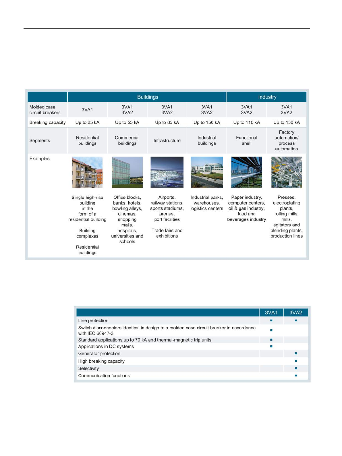
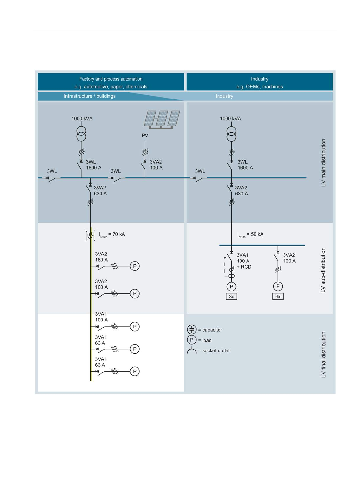
The two tables below show examples of applications and possible uses for the new 3VA
molded case circuit breakers.
3VA molded case circuit breakers
Manual, 04/2015, A5E03603177010-02
15
Description
Possible uses
Functions and applications
2.1 Overview - applications and portfolio
3VA molded case circuit breakers can be deployed in various fields where they perform a
variety of different protection tasks. The following table (sorted according to breaking
capacity) shows the areas in which 3VA molded case circuit breakers are used:
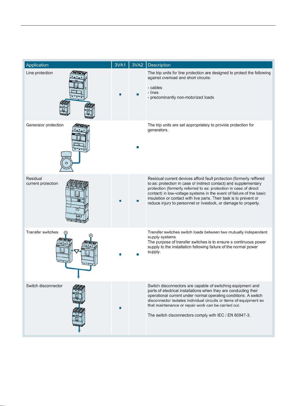
3VA molded case circuit breakers are used in a variety of functions, as shown in the table
below:
3VA molded case circuit breakers
16 Manual, 04/2015, A5E03603177010-02
Description
2.1.2
Portfolio
Sizes
2.1 Overview - applications and portfolio
Molded case circuit breakers are primarily designed for the following applications:
● Subdistribution systems
● Industrial distribution systems
● Final distribution systems
● On-site isolation
● Use in machines
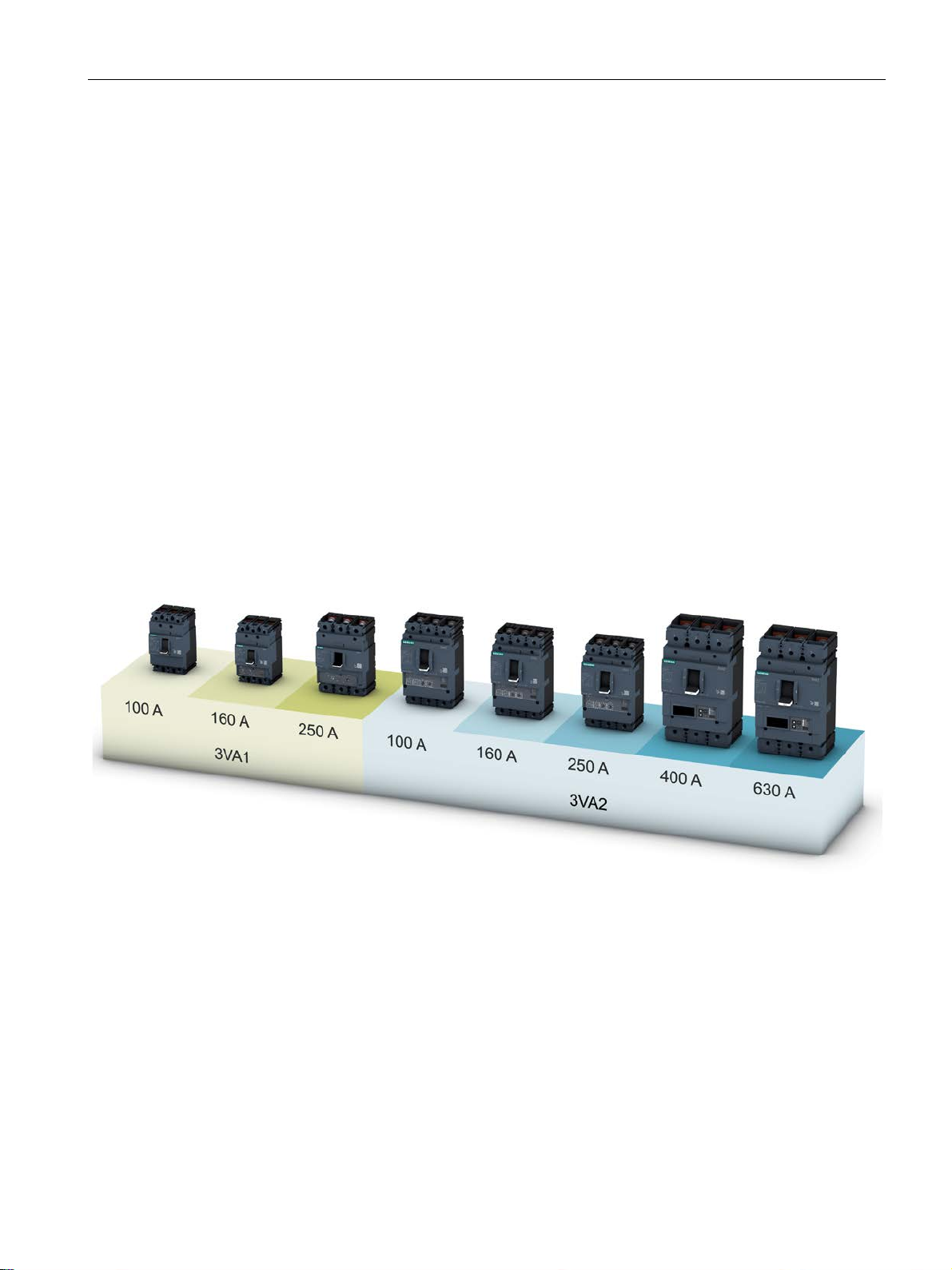
The integrated 3VA portfolio consists of two different series of molded case circuit breakers
in five different rated operational current versions (sizes).
The new 3VA molded case circuit breakers set new standards in flexibility and the variety of
modular accessories available. Standardized accessories suitable for use with several sizes
of circuit breaker from all the 3VA ranges help to cut costs and save time.
The new 3VA1 molded case circuit breakers are available in 1 to 4-pole versions (3VA1 160
A) or in 3 and 4-pole versions (3VA1 100 A or 3VA1 250 A). The new 3VA2 molded case
circuit breakers are available in 3 and 4-pole versions.
The circuit breakers are available with rated operational currents ranging from 16 A to 630 A
and rated voltages up to 690 V, depending on the series and size.
3VA molded case circuit breakers
Manual, 04/2015, A5E03603177010-02
17

Description
3VA1 molded case circuit breakers
Features
Compact dimensions
Thermal-magnetic trip units
2.1 Overview - applications and portfolio
The new 3VA1 molded case circuit breakers reliably perform all the tasks associated with
line protection.
The key features of the 3VA1 series are:
● Compact design
● Depending on size: 1 and 2-pole versions in size 160 A, 3 and 4-pole versions in sizes
100 A, 160 A and 250 A
● Depending on size: Breaking capacity of 16 kA ... 70 kA at 415 V, 3 or 4-pole breakers
and 36 kA at 240 V,1-pole breakers
● Fixed-mounted, plug-in version
● Thermal-magnetic trip units
● AC/DC applications
● No derating up to +50 °C
● Modular and easy-to-fit internal accessories with diverse functions
● Uniform accessories platform across all 3VA molded case circuit breakers
Thanks to a mounting depth of 70 mm and a cover size of 45 mm, the 3VA1 molded case
circuit breakers of sizes 100 A, 160 A and 250 A are ideal for protecting cables and lines in
the plant area, especially for the INSTA electrical installation area. For these applications,
there is also a wide range of accessories available such as adapters for installation on DIN
rails, as well as residual current devices (RCD310 and RCD510) that can be side mounted.
3VA1 molded case circuit breakers are equipped with a thermal-magnetic trip unit which
provides overload and short-circuit protection. This has been developed for implementing
economical, cost-efficient installations up to 250 A. It is suitable for use in three-phase
networks, AC networks, 400 Hz applications, and with DC currents.
3VA molded case circuit breakers
18 Manual, 04/2015, A5E03603177010-02

Description
3VA2 molded case circuit breakers
Features
2.1 Overview - applications and portfolio
The new 3VA2 molded case circuit breakers reliably perform all the tasks associated with
line and generator protection.
This series is designed for applications with more exacting requirements:
● Increased breaking capacity
● Excellent selective protection
● Integrated metering function
● Connection to a fieldbus communication system
The most important features of the 3VA2 series are:
● Compact dimensions
● 3 and 4-pole versions
● Four breaking capacity classes from 55 kA … 150 kA
● Fixed-mounting, plug-in technology, draw-out technology
● Depending on size: Selective tripping at rated operational current difference 1 : 2.5
● Electronic Trip Units
● Retrofittable communication for ETU 5-series and 8-series
● Depending on the ETU: Integrated metering function
● AC applications
● No derating up to +50 °C
● Modular and easy-to-fit internal accessories with diverse functions
● Uniform accessories platform across all 3VA molded case circuit breakers
● Electronic Trip Units (ETU) with different setting values
3VA molded case circuit breakers
Manual, 04/2015, A5E03603177010-02
19

Description
Compact dimensions with function expansions
Selective contact system
Electronic Trip Unit (ETU)
2.1 Overview - applications and portfolio
In addition to its expanded functionality, the 3VA2 molded case circuit breaker also comes
with compact dimensions for fixed mounting, as a plug-in version and a draw-out version.
A cover size of 70 mm for the door cutout and a complete selection of breaking capacity
classes from 55 kA to 150 kA at 415 V AC provide the necessary flexibility for planning.
Despite its compact size, the circuit breaker offers the following benefits:
● Extremely high breaking capacity
● Extremely good selectivity
● Electronic trip units, versions with and without integrated metering function and optional
fieldbus communication interface
With its contact system, the 3VA2 molded case circuit breaker is designed for fast selectivity
tripping. The selective contact system ensures the following:
● Dynamic instantaneous short-circuit range
● High breaking capacity
● Selective protection response of the molded case circuit breakers in relation to each other
● Selective protection response of the molded case circuit breakers in relation to other
protection devices such as downstream low-voltage fuses, etc.
The current sensor of the 3VA2 comprises an iron-cored transformer for the internal power
supply and a Rogowski coil for precise current measurement. Each transformer can be
optimized accordingly for its specific task. Thanks to the high accuracy of current
measurement, the 3VA2 molded case circuit breaker is suitable for power/energy
measurement. In addition, finer adjustment of ground fault current monitoring is possible.
The Electronic Trip Units (ETUs) provide the following protection functions:
● Overload protection L ("L" = Long-time delay)
Adjustable in steps from 40% to 100% of the rated operational current of the molded case
circuit breaker.
● Short-time delayed short-circuit protection S ("S" = Short-time delay) for time-selective
response in case of a short circuit
● Instantaneous short-circuit protection I ("I" = instantaneous):
● Protection of the neutral conductor against overload and short-circuit ("N" = neutral)
● Protection against residual currents to ground ("G" = Ground fault).
3VA molded case circuit breakers
20 Manual, 04/2015, A5E03603177010-02

Description
Energy management and communication
2.1 Overview - applications and portfolio
The Electronic Trip Units (ETUs) provide the following energy management and
communication functions:
● Metering functions
● Communication
● Flexible, local, digital inputs and outputs via the EFB300 external function box
● Software commissioning support with powerconfig
● Testing and archiving with the TD300 and TD500 test devices (with powerconfig)
3VA molded case circuit breakers
Manual, 04/2015, A5E03603177010-02
21
Description
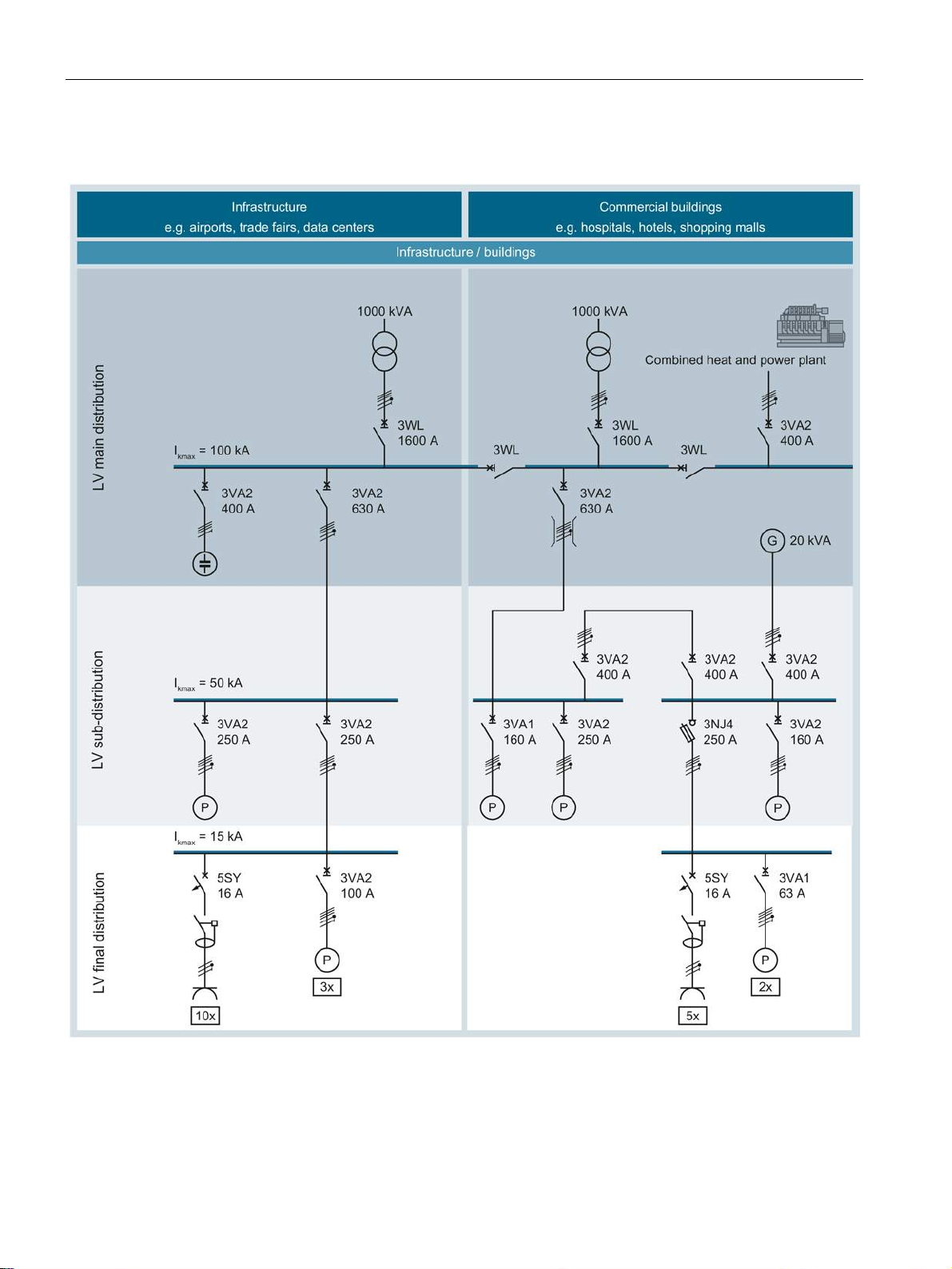
2.1.3
Application examples
2.1 Overview - applications and portfolio
3VA molded case circuit breakers
22 Manual, 04/2015, A5E03603177010-02
Description
2.1 Overview - applications and portfolio
3VA molded case circuit breakers
Manual, 04/2015, A5E03603177010-02
23
Description
2.1.4
Detailed information about applications and possible uses
See also
2.1 Overview - applications and portfolio
Applications (Page 105)
3VA molded case circuit breakers
24 Manual, 04/2015, A5E03603177010-02
Description
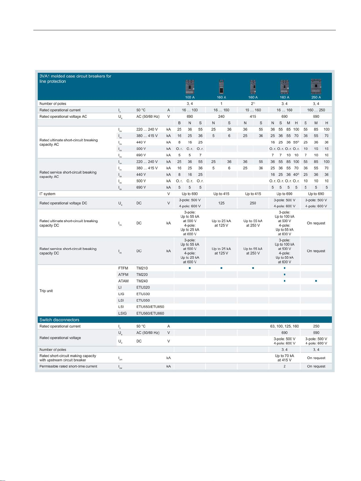
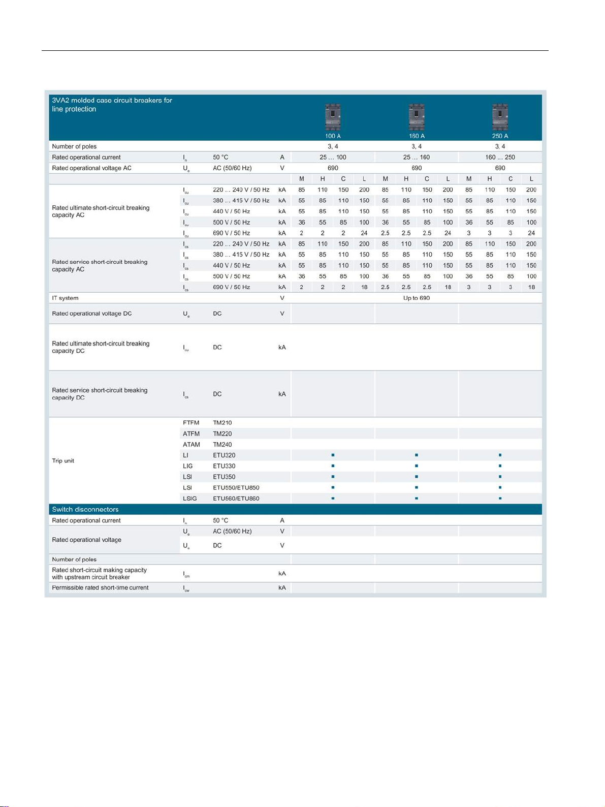
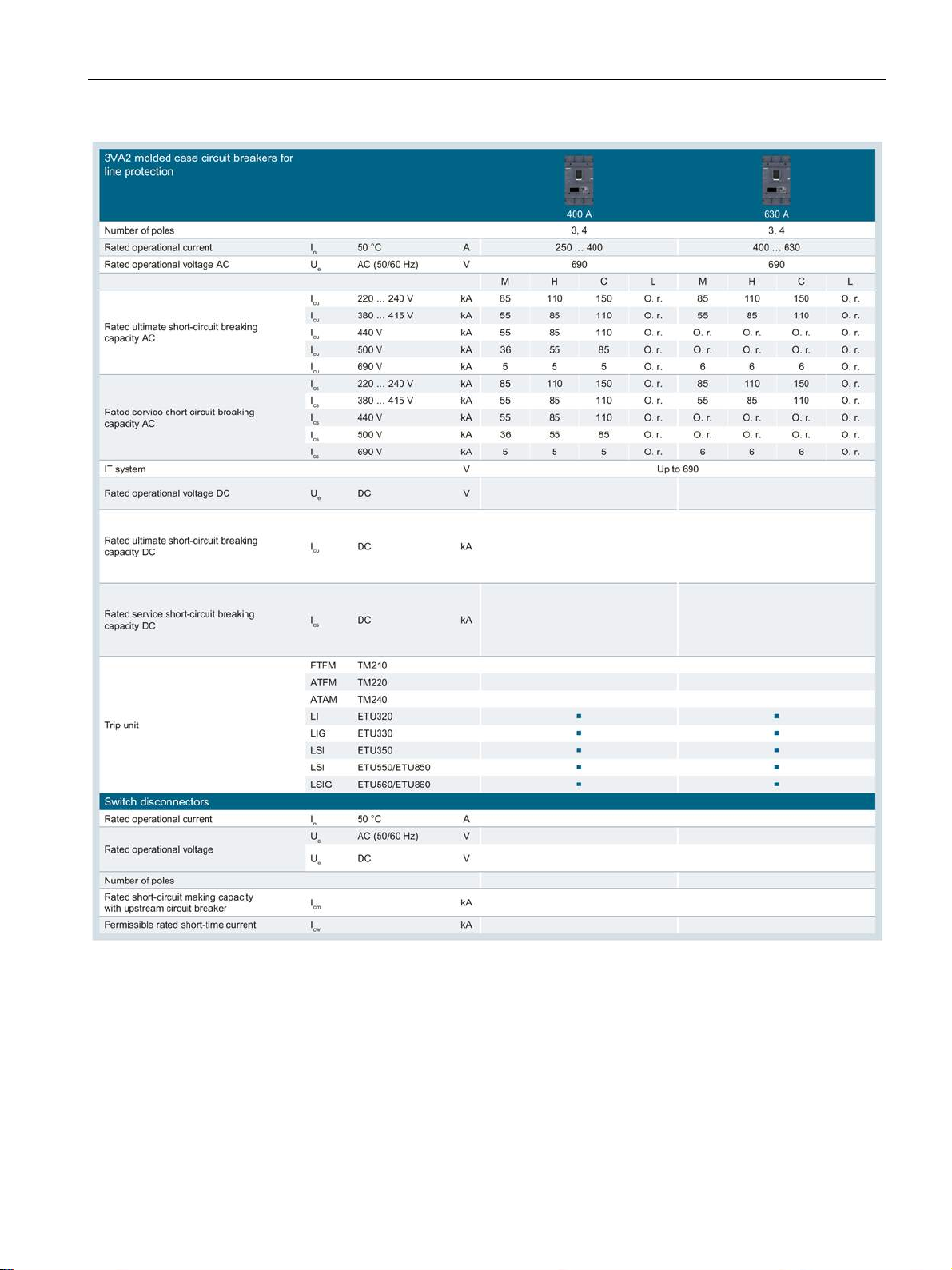
2.1.5
Technical specifications
2.1 Overview - applications and portfolio
O. r. On request
1)
A side plate must be installed (see chapter Insulating equipment (Page 191)) if the installation conditions on the
right-hand side are such that the device is not finger-safe.
2)
In 125 A, 160 A: I
/ Ics = 36 kA / 36 kA
cu
3VA molded case circuit breakers
Manual, 04/2015, A5E03603177010-02
25
Description
2.1 Overview - applications and portfolio
3VA molded case circuit breakers
26 Manual, 04/2015, A5E03603177010-02
Description
2.1 Overview - applications and portfolio
O. r. On request
3VA molded case circuit breakers
Manual, 04/2015, A5E03603177010-02
27
Description
2.1.6
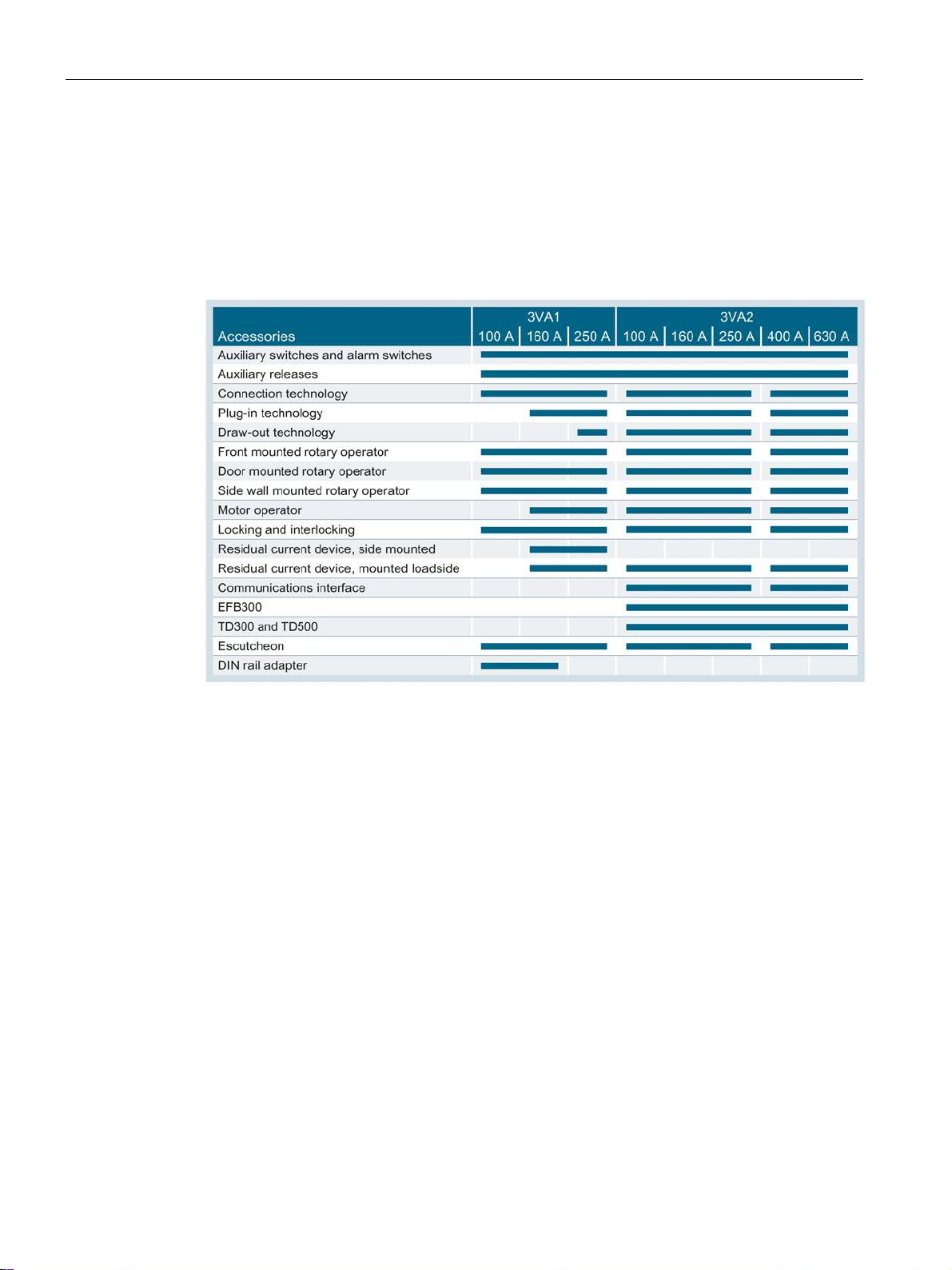
Molded case circuit breakers and accessories in the system
2.1 Overview - applications and portfolio
The new 3VA molded case circuit breakers come with a large portfolio of internal and
external accessories which can be installed flexibly in any size of circuit breaker (depending
on the type of accessory).
The table below indicates which accessories are compatible with particular molded case
circuit breakers, and which sizes of breakers are compatible with the same accessory:
3VA molded case circuit breakers
28 Manual, 04/2015, A5E03603177010-02

Description
2.1 Overview - applications and portfolio
3VA molded case circuit breakers
Manual, 04/2015, A5E03603177010-02
29
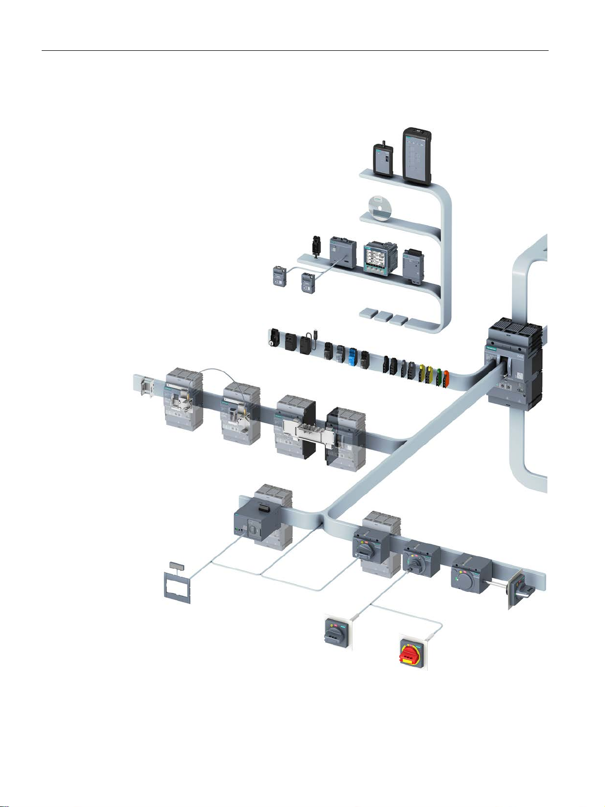
Description
Overview of accessories in the system
2.1 Overview - applications and portfolio
3VA molded case circuit breakers
30 Manual, 04/2015, A5E03603177010-02
 Loading...