


R-209FW
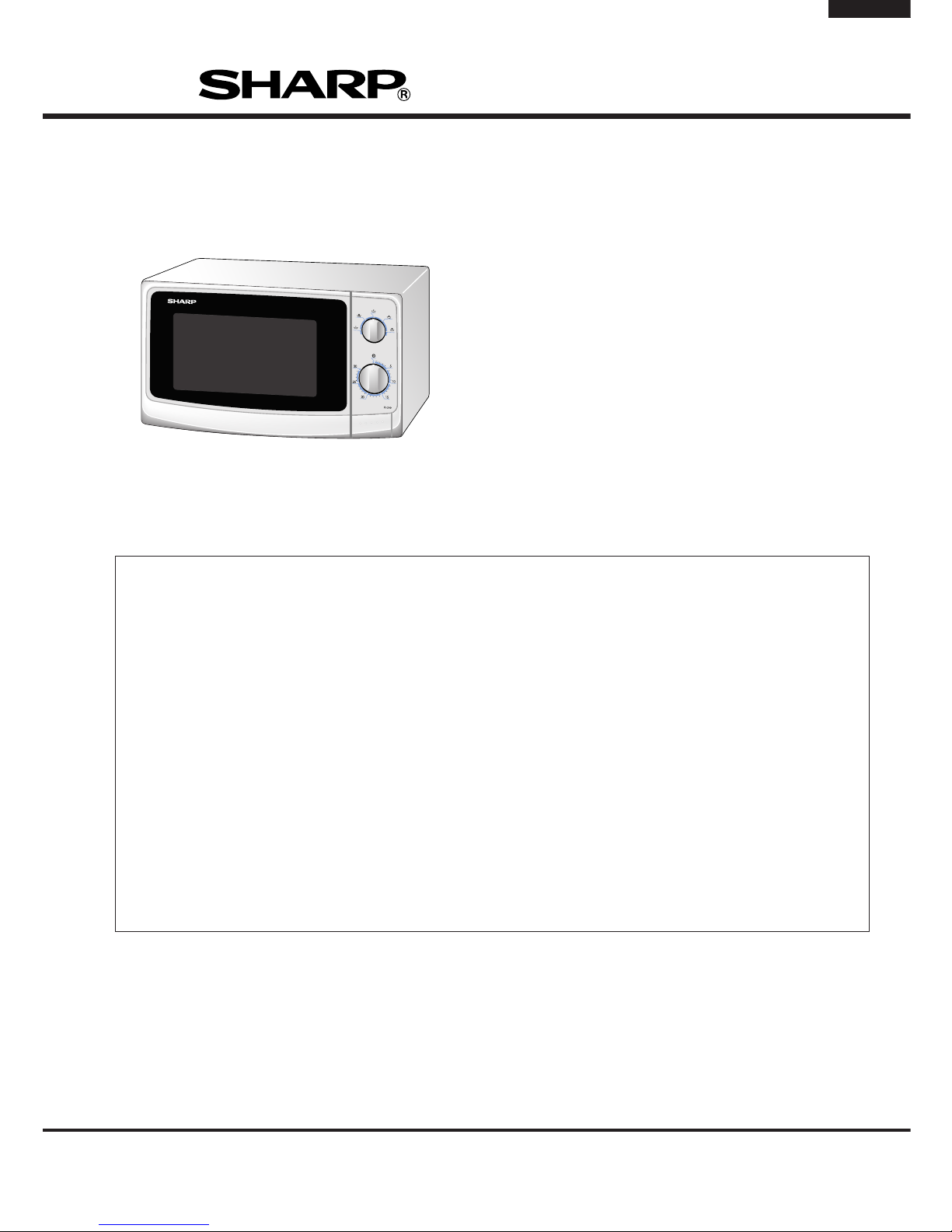
R-209(IN)
R-209(W)
R-209(Y)
TABLE OF CONTENTS
Page
CAUTION, MICROWAVE RADIATION................................................................. INSIDE FRONT PAGE
WARNING.................................................................................................................................................1
SERVICING ............................................................................................................................................. 2
PRODUCT SPECIFICATIONS .................................................................................................................5
GENERAL INFORMATION.......................................................................................................................5
APPEARANCE VIEW .............................................................................................................................. 6
OPERATION SEQUENCE........................................................................................................................7
FUNCTION OF IMPORTANT COMPONENTS ....................................................................................... 8
TROUBLESHOOTING GUIDE ................................................................................................................. 9
TEST PROCEDURE .............................................................................................................................. 10
CONTROL PANEL ASSEMBLY ............................................................................................................15
COMPONENT REPLACEMENT AND ADJUSTMENT PROCEDURE .................................................. 18
MICROWAVE MEASUREMENT ........................................................................................................... 23
TEST DATA AT A GLANCE .................................................................................................................. 24
WIRING DIAGRAM ................................................................................................................................ 25
PICTORIAL DIAGRAM .......................................................................................................................... 26
CONTROL PANEL CIRCUIT ..................................................................................................................27
PRINTED WIRING BOARD ....................................................................................................................28
PARTS LIST .......................................................................................................................................... 29
S3408R209PHW/
MICROWAVE OVEN
MODELS
R-209(IN)
R-209(W)
R-209(Y)
In interests of user-safety the oven should be restored to its original
condition and only parts identical to those specified should be used.
SERVICE MANUAL
SHARP CORPORATION

R-209(IN)
R-209(W)
R-209(Y)
CAUTION
MICROWAVE RADIATION
Personnel should not be exposed to the microwave energy which may radiate from the
magnetron or other microwave generating devices if it is improperly used or connected.
All input and output microwave connections, waveguides, flanges and gaskets must be
secured.
Never operate the device without a microwave energy absorbing load attached.
Never look into an open waveguide or antenna while the device is energized.
VARNING
MICKROVAGSSTRALING
Personal får inte utsättas för mikrovågsenergi som kan ustrala från magnetronen eller
andre mikrovågsalstrande anordningar om dessa är felanslutna eller används på fel sätt.
Alla in-och utgångsanslutningar för mikrovågor, vagledare, flänsar och packningar måste
vara fast anslutna.
Mikrovågsgeneratorn får inte arbeta utan att absorberande belastning är ansluten. Titta
aldrig in i ën öppen vågledare eller antenn när mikrovågsgeneratorn är påkopplad eller
laddad.
VAROITUS
MIKROAALTOSÄTELYÄ
Käyttäjä ei saa joutua alttiiksi mikroaaltoenergialle, jota voi säteillä magnetronista tai
muusta mikroaaltoja kehittävästä laitteesta, jos sitä käytetään tai jos se kytketään väärin.
Kaikkien mikroaaltoliitäntöjen sekä syöttö-että ulostulopuolella, aaltoputkien laippojen ja
tiivisteiden tulee olla varmistettuja.
Mikroaaltouunnia ei koskaan saa käyttää ilman kuormaa jossa mikroaaltoenergiaa kuluu.
Avoimeen aaltoputkeen tai antenniin ei koskaan saa katsoa virran ollessa kytkettynä.
ADVARSEL
MIKROBØLGESTRÅLING
Personell må ikke utsettes for mikrobølge-energi som kan utståles fra magnetronen eller
andre mikrobølge-generende deler dersom apparatet feilbetjenes eller blir feiltikoplet.
Alle inn-og ut-tilkoplinger i forbindelse med mikrobølge-strålingen, bølgeledere, flenser og
tetningsringer/pakninger må festes ordentlig.
Aldri bruk apparatet med mindre en mikrobålge-absorberende last er plassert i
ovnsrommet.
Aldri se direkte inn i en åpen bølgeleder eller antenne imens apparatet er strømførende.
ADVARSEL
MIKROBØLGEBESTRÄLING
Man bør ikke udsætte sig for mikrobølgebestråling fra magnetronen eller andre
mikrobølgefrembringende anordninger, hvilket kan ske hvis apparatet er forkert tilsluttet
eller bruges forkert. Alle mikrobølgeindgange og-udgange, bølgeledere, flanger og
tætningsstrimler må være forsvarligt udført.
Anvend aldrig ovnen uden en mikrobølgesabsorberende anordning. Se aldrig ind i en
åben bølgeleder eller antenne, mens ovnen er i brug.
R-209(IN)
R-209(W)
R-209(Y)
1
WARNING
Never operate the oven until the following points are ensured.
(A) The door is tightly closed.
(B) The door brackets and hinges are not defective.
(C) The door packing is not damaged.
(D) The door is not deformed or warped.
(E) There is not any other visible damage with the oven.
Servicing and repair work must be carried out only by trained
service engineers.
Removal of the outer wrap gives access to potential above 250V.
All the parts marked "∆" on the parts list may cause undue
microwave exposure, by themselves, or when they are damaged, loosened or removed.
SHARP CORPORATION
OSAKA, JAPAN
SERVICE MANUAL
MICROWAVE OVEN
R-209(IN)/ R-209(W)/ R-209(Y)
GENERAL IMPORTANT INFORMATION
This Manual has been prepared to provide Sharp Corp. Service
engineers with Operation and Service Information.
It is recommended that service engineers carefully study the entire
text of this manual, so they will be qualified to render satisfactory
customer service.
WARNING
Note: The parts marked "*" are used at voltage more
than 250V. (Parts List)
Anm: Delar märket med "*" har en spänning
överstigande 250V.
Huom: Huolto-ohjeeseen merkitty "tähdella" osat
joissa jännite on yli 250 V.
Bemerk: Deler som er merket "asterisk" er utsatt for
spenninger over 250V til jord.
Bemærk: "Dele mærket med stjerne benyttes med
højere spænding end 250 volt.
SERVICING
PRODUCT SPECIFICATIONS
GENERAL INFORMATION
APPEARANCE VIEW
OPERATING SEQUENCE
FUNCTION OF IMPORTANT
COMPONENTS
TROUBLESHOOTING GUIDE
AND TEST PROCEDURE
TOUCH CONTROL PANEL
COMPONENT REPLACEMENT
AND ADJUSTMENT PROCEDURE
MICROWAVE MEASUREMENT
TEST DATA AT A GLANCE
WIRING DIAGRAM
PARTS LIST
R-209(IN)
R-209(W)
R-209(Y)
2
REMEMBER TO CHECK 3D
1) Disconnect the supply.
2) Door opened, and wedged open.
3) Discharge high voltage capacitor.
WARNING: AGAINST THE CHARGE OF THE HIGH-
VOLTAGE CAPACITOR
The high-voltage capacitor remains charged about 60 seconds after the oven has been switched off. Wait for 60
seconds and then short-circuit the connection of the highvoltage capacitor (that is, of the connecting lead of the highvoltage rectifier) against the chassis with the use of an
insulated screwdriver.
Sharp recommend that wherever possible fault-finding is
carried out with the supply disconnected. It may in, some
cases, be necessary to connect the supply after the outer
case has been removed, in this event carry out 3D checks and
then disconnect the leads to the primary of the power transformer. Ensure that these leads remain isolated from other
components and the oven chassis. (Use insulation tape if
necessary.) When the testing is completed carry out 3D
checks and reconnect the leads to the primary of the power
transformer.
SERVICING
WARNING TO SERVICE PERSONNEL
GB Microwave ovens contain circuitry capable of producing very high voltage and current, contact with following parts will
result in electrocution.
High voltage capacitor, Power transformer, Magnetron, High voltage rectifier assembly, High voltage harness.
REMEMBER TO CHECK 4R
1) Reconnect all leads removed from components during
testing.
2) Replace the outer case (cabinet).
3) Reconnect the supply.
4) Run the oven. Check all functions.
Microwave ovens should not be run empty. To test for the
presence of microwave energy within a cavity, place a cup of
cold water on the oven turntable, close the door and set the
power to HIGH and set the microwave timer for two (2) minutes.
When the two minutes has elapsed (timer at zero) carefully
check that the water is now hot. If the water remains cold carry
out
3D checks and re-examine the connections to the compo-
nent being tested.
When all service work is completed, and the oven is fully
assembled, the microwave power output should be checked and
a microwave leakage test should be carried out.
NL Magnetronovens bevatten circuits die een zeer hoge spanning en stroom kunnen voortbrengen. Contact met de
volgende onderdelen kan elektrocutie tot gevolg hebben.
Hoogspanningscondensator, hoogspanningstransformator, magnetron, hoogspanningsgelijkrichter, hoogspannings
kabelboom.
VERGEET DE VOLGENDE 3 STAPPEN NIET
1) Haal de stekker uit het stopcontact.
2) Open de deur en zorg ervoor dat hij niet dicht kan vallen.
3) Ontlaad de hoogspanningscondensator.
PAS OP VOOR DE ELECTRISCHE LADING VAN DE
HOOGSPANNINGSCONDENSATOR
De hoogspanningscondensator blijft nog ongeveer 60
seconden lang opgeladen, nadat de oven is uitgeschakeld.
Wacht 60 seconden voordat u de verbinding van de
hoogspannings-condensator (m.a.w. de verbindingsdraad
van de hoogspanningsgelijkrichter) met een geïsoleerde
schroevedraaier kortsluit tegen het chassis.
Sharp beveelt ten sterkste aan dat, voor zover mogelijk,
defecten worden opgespoord wanneer de stekker uit het
stopcontact is gehaald. Soms is het nodig om de stroomtoevoer
weer tot stand te brengen nadat de buitenmantel verwijderd
is. Herhaal dan de bovengenoemde 3 stappen en haal de
electrische draden uit de primaire zijde van de
vermogenstransformator. Zorg ervoor dat deze draden
geïsoleerd blijven van andere elementen en van het chassis
van de oven. (Gebruik zo nodig isolatieband.) Wanneer de
test is uitgevoerd, herhaalt u de bovenstaande 3 stappen en
verbindt u de electrische draden weer aan de primaire zijde
van de vermogenstransformator.
VERGEET DE VOLGENDE 4 STAPPEN NIET
1) Sluit de draden weer aan diezijn losgehaald voor de test.
2) Plaats de buitenmantel weer om het toestel heen (kabinet).
3) Stop de stekker weer in het stopcontact.
4) Zet de oven aan. Controleer alle functies.
Magnetronovens mogen niet leeg aangezet worden. Om te
controleren of er microgolf-energie binnen de oven wordt
geproduceerd, plaatst u een mok met koud water op de
draaitafel van de oven, sluit de deur, zet de oven op HIGH en
stelt de klok van de magnetron in op twee (2) minuten. Wanneer
de twee minuten voorbij zijn (klok staat op nul), controleert u
voorzichtig of het water heet is. Indien het water nog steeds
koud is, herhaalt u de allereerste drie stappen en controleer
nogmaals de aansluitingen naar de geteste onderdelen.
Wanneer alle reparaties zijn uitgevoerd en de oven weer in
elkaar is gezet, moet de het magnetronvermogen worden
gecontroleerd en moet worden gecontroleerd of er geen
microgolflekkage is.
R-209(IN)
R-209(W)
R-209(Y)
3
E Los hornos de microondas contienen circuitos eléctricos capaces de producir voltajes de alta tensión y descargas
eléctricas. Para evitar el riesgo de electrocución, absténgase de tocar los siguientes componentes: condensador de alta
tensión, transformador de alta tensión, magnetrón, dispositivo del rectificador de alta tensión y arnés de alta tensión.
RECUERDE LA COMPROBACION 3D
1) Desconecte la alimentación.
2) Deje la puerta abierta y calzada.
3) Descargue el condensador de alto voltaje.
ADVERTENCIA SOBRE LA CARGA DEL
CONDENSADOR DE ALTO VOLTAJE
El condensador de alto voltaje permanece cargado unos
60 segundos después de haber apagado el horno. Espere
60 segundos y luego ponga en cortocircuito la conexión del
condensador de alto voltaje (esto es, del conductor de
conexión del rectificador de alto voltaje) al chasis con un
destornillador de mango aislado.
Se recomienda encarecidamente que siempre que sea
posible la localización de fallos se realice con la alimentación
desconectada. Puede ser que en algunos casos sea
necesario conectar la alimentación después de haber retirado
la carcasa exterior. En este caso, realice las comprobaciones
3D y luego desconecte los conductores del primario del
transformador de alimentación. Asegúrese de que estos
conductores permanezcan aislados de otros componentes y
del chasis del horno. (Use cinta aislante si es necesario).
Cuando termine la prueba efectúe las comprobaciones 3D y
reconecte los conductores al primario del transformador de
alimentación.
RECUERDE LA COMPROBACION 4C
1) Conecte todos los componentes desconectados de los
componentes durante la prueba.
2) Coloque la carcasa exterior (cabina).
3) Conecte la alimentación.
4) Compruebe todas sus funciones despues de poner en
marcha el horno.
Los hornos de microondas no deben funcionar vacíos. Para
comprobar la presencia de energía de microondas dentro de
una cavidad, coloque una taza de agua fría en el plato giratorio
del horno, cierre la puerta y ponga la potencia en HIGH (alta)
y coloque el temporizador en dos (2) minutos. Cuando
transcurran los dos minutos (temporizador a cero) compruebe
cuidadosamente que el agua se ha calentado. Si el agua
permaneciese fría, efectúe las comprobaciones 3D y vuelva a
examinar las conexiones de los componentes que han sido
probados.
Cuando haya terminado la intervención en el equipo y el horno
haya sido ensamblado de nuevo completamente, deberá
comprobar la potencia de salida de microondas y realizar una
prueba de fugas de microondas.
SV Mikrovågsugnar innehåller kretsar som producerar mycket höga spänningar och strömmar.
Kontakt med följande komponenter kan leda till dödsfall:
Högspänningskondensator, transformator, magnetron, högspännings likriktare, högspännings kablage.
KOM IHÅG ATT KONTROLLERA 3 STEG
1) Koppla från strömkällan.
2) Öppna dörren på glänt.
3) Ladda ur högspänningskondensatorn.
VARNING FÖR LADDNINGEN I
HÖGSPÄNNINGSKONDENSATORN
Högspänningskondensatorn är laddad i 60 sekunder efter
det att ugnen stängts av. Vänta 60 sekunder och korislut
sedan kondensatoms anslutning (dvs anslutningen till
högspänningslikriktaren) till chassiet med hjälp av en isolerad
skruvmejsel.
Sharp rekommenderar att felsökning sker med strömmen
fränkopplad. Ibland kan det var nödvändigt att koppla på
strömmen efter det att höljet avlägsnats, utför da 3 Steg
kontrollen och koppla sedan från ledarna till transformatorns
primärsida. Se till att ledarna är isolerade från andra
komponenter och chassiet. (Använd isoleringsband om det
behövs). När Du testat färdigt utför Du 3 Steg kontrollen och
ansluter ledningarna till transformatorns primärsida igen.
KOM IHÅG ATT KONTROLLERA 4 STEG
1) Anslut alla ledningar som använts vid testning
2) Sätt tillbaka ytterhöljet.
3) Anslut strömkällan på nytt.
4) Sätt på ugnen. Kontrollera alla funktioner.
Mikrovågsugnar får inte användas tomma. Kontrollera
mikrovågsstrålningen i olika delar av ugnen genom att placera
en kopp med kallt vatten på ugnens tallrik, stäng dörren, ställ
in HIGH och ställ in 2 minuter på timern. När två minuter har gått
(timem visar 0) kontrollerar du om vattnet är varmt. Om vattnet
fortfarande är kallt utför Du 3 steg kontroller och kontrollerar
anslutningarna till varje enskild komponent på nytt.
När all service är klar och ugnen ihopskruvad skall ugnens
uteffekt och eventuellt mikrovågsläckage kontrolleras.
R-209(IN)
R-209(W)
R-209(Y)
4
II forni a microonde contengono un circuito elettrico in grado di generare tensioni e correnti estremamente elevate.
L’eventuale contatto con i seguenti componenti può causare la folgorazione:
condensatore ad alta tensione; trasformatore ad alta tensione; magnetron; rettificatore alta tensione; cablaggio ad
alta tensione.
TRE OPERAZIONI IMPORTANTI PER
INCOMINCIARE
1) Scollegare l'alimentazione elettrica.
2) Verificare che la porta sia bloccata in posizione
aperta.
3) Scaricare il condensatore ad alta tensione.
ATTENZIONE AL CONDENSATORE AD ALTA
TENSIONE: PUO ESSERE CARICO
Il condensatore ad alta tensione rimane carico per circa
60 secondi dopo lo spegnimento del forno. Occorre quindi
spettare 60 secondi prima di cortocircuitare, utilizzando
un cacciavite con impugnatura isolata, il collegamento
del condensatore ad alta tensione (cioè del conduttore
di collegamento del raddrizzatore ad alta tensione) sul
telaio del forno.
Sharp raccomanda, nei limiti del possibile, che la ricerca
dei guasti avvenga in assenza di alimentazione elettrica.
In alcuni casi tuttavia, può essere necessario alimentare
l'apparecchio dopo aver rimosso la scatola esterna. In
questo caso eseguire i tre controlli sopra citati e quindi
scollegare i connettori dal primario del trasformatore.
Assicurarsi che tali connettori non vengano a contatto con
altri componenti, ne con il telaio del forno (fare uso, se
necessario, di nastro isolante). Al termine dell'intervento,
eseguire nuovamente i tre controlli e ricollegare i conduttori
al primario del trasformatore.
QUATTRO VERIFICHE IMPORTANTI DA NON
DIMENTICARE
1) Ricollegare tutti i conduttori staccati dai vari componenti
durante l'intervento.
2) Rimontare la scatola esterna.
3) Ripristinare l'alimentazione elettrica.
4) Rimettere in funzione il forno. Controllare tutte le funzioni.
I forni a microonde non devono mai funzionare a vuoto. Per
verificare la presenza di energia da microonde all'interno
di una cavitá, mettere una tazza di acqua fredda sul piatto
rotante del forno, chiudere la porta, regolare la potenza su
HIGH ed impostate il temporizzatore su due (2) minuti.
Tr ascorsi i due minuti (temporizzatore a zero), controllare
accuratamente che ora l'acqua sia calda. Se l'acqua è
rimasta fredda, eseguire i tre controlli iniziali e verificare
nuovamente i collegamenti del componente in questione.
Dopo aver portato a termine le operazioni di manutenzione
e rimontato il forno, è necessario controllare la potenza delle
microonde emesse ed eseguire un test per verificare che
non vi sia alcuna dispersione.
R-209(IN)
R-209(W)
R-209(Y)
5
PRODUCT DESCRIPTION
SPECIFICATION
ITEM DESCRIPTION
Power Requirements 230 Volts
50 Hertz
Single phase, 3 wire earthed
Power Consumption 1.18 kW
Power Output
800 W nominal of RF microwave energy (measured by method of IEC 60705)
Operating fequency 2450 MHz
Case Dimensions Width 460 mm
Height 281 mm including foot
Depth 360 mm
Cooking Cavity Dimensions Width 322 mm
Height 187 mm
Depth 336 mm
Turntable diameter 272 mm
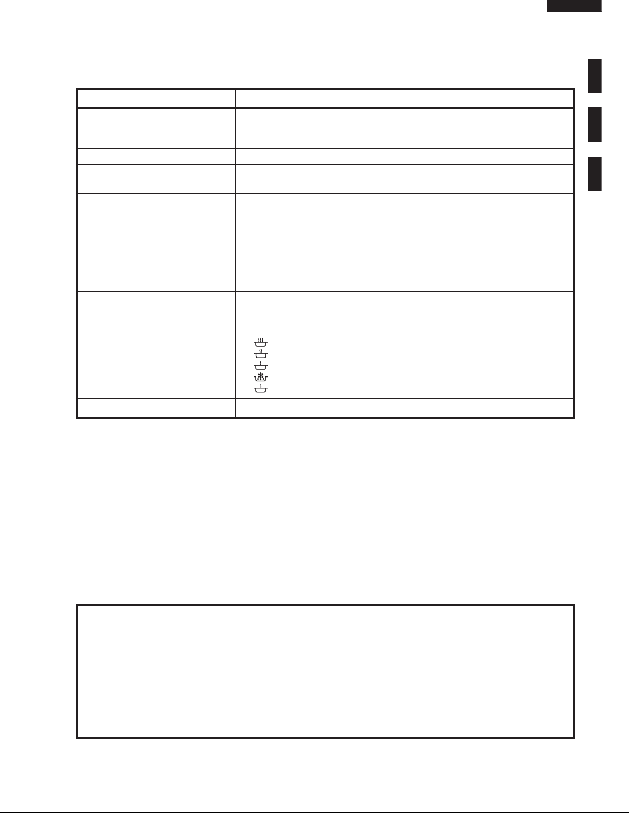
Control Complement Timer (0 - 30 minutes)
Microwave Power for Variable Cooking
Repetition Rate;
800W ............................... Full power throughout the cooking time
560W ................................................. approx. 70% of Full Power
400W ................................................. approx. 50% of Full Power
240W ................................................. approx. 30% of Full Power
80W ................................................... approx. 10% of Full Power
Set Weight Approx. 12 kg
GENERAL INFORMATION
WARNING
THIS APPLIANCE MUST BE EARTHED
IMPORTANT
THE WIRES IN THIS MAINS LEAD ARE COLOURED IN ACCORDANCE WITH THE FOLLOWING CODE:
GREEN-AND-YELLOW : EARTH
BLUE : NEUTRAL
BROWN : LIVE
NOTE: Internal capacity is calculated by measuring
maximum width, depth and height.
Actual capacity for holding food is less.
R-209(IN)
R-209(W)
R-209(Y)
6
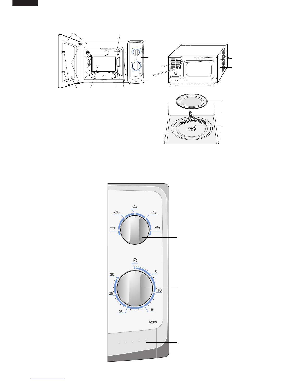
MICROWAVE POWER
CONTROL knob
TIMER knob (0 - 30 minutes)
DOOR OPENING BUTTON
APPEARANCE VIEW
OVEN
1. Control panel
2. Door opening button
3. Waveguide cover
4. Seal packing
5. Oven cavity
6. Door
7. Door safety latch
CONTROL PANEL
8. Door hinges
9. Door seals and sealing surfaces
10.Oven lamp
11.Ventilation openings
12.Outer case
13.Power cord
Turntable
Roller stay
Seal packing
1. Place the roller stay on the floor of the oven cavity,
engaging shaft into turntable motor shaft.
2. Then place the turntable on the roller stay.
12
11
13
5
10
9
8
7
64
37
1
2
R-209(IN)
R-209(W)
R-209(Y)
7
OPERATION SEQUENCE
OFF CONDITION
1. When the timer knob is at " ", the oven is OFF
condition.
2. Closing the oven door activates the monitored latch
switch and the latch switch.
IMPORTANT
When the oven door is closed, the contacts (COM-NC) of
the monitor switch SW2 must be open.
When the microwave oven is plugged in a wall outlet, rated
voltage is supplied to the noise filter and the control unit.
Figure O-1 on page 25
MICROWAVE COOKING CONDITION
HIGH COOKING
Set the Microwave power control knob to 800W and
then set the timer.
Function sequence
Figure O-2 on page 25
1. Following components are energized.
High voltage rectifier High voltage transformer
High voltage capacitor High voltage fuse
Turntable motor Timer motor Fan motor
Magnetron Oven lamp Control unit
CONNECTED COMPONENTS RELAY
High voltage transformer RY1
2. Rated voltage is supplied to the primary winding of the
high voltage transformer T. The voltage is converted to
about 3.3 volts A.C. output on the filament winding and
high voltage of approximately 2000 volts A.C. on the
secondary winding.
3. The filament winding voltage (3.3 volts) heats the
magnetron filament and the high voltage (2000 volts) is
sent to the voltage doubling circuit, where it is doubled
to negative voltage of approximately 4000 volts D.C..
4. The 2450 MHz microwave energy produced in the
magnetron MG generates a wave length of 12.24 cm.
This energy is channelled through the waveguide
(transport channel) into the oven cavity, where the food
is placed to be cooked.
5. When the cooking time is up, the timer returns to " ",
the bell rings and the contacts of the timer switch are
opened. The following components are turned off.
High voltage rectifier High voltage transformer
High voltage capacitor High voltage fuse
Turntable motor Timer motor Fan motor
Magnetron Oven lamp Control unit
6. When the oven door is opened during a cook cycle, the
switches come to the following position and they are
common to the other cooking conditions too.
CONDITION
DURING DOOR OPEN
SWITCH CONTACT COOKING
(NO COOKING)
Monitored latch switch
COM-NO Closed Open
Latch switch COM-NO Closed Open
Monitor switch COM-NC Open Closed
The circuits to the high voltage transformer T, turntable
motor TTM, timer motor TM, fan motor FM, oven lamp
OL and control unit are cut off when the contacts
(COM-NO) of the monitored latch switch SW1 and
latch switch SW3 are made open.
The timer stops to indicate how much cooking time
remains.
7. MONITOR SWITCH CIRCUIT
The monitor switch SW2 is mechanically controlled by
oven door, and monitors the operation of the monitored
latch switch SW1.
7-1 When the oven door is opened during or after the
cycle of a cooking program, the monitored latch
switch SW1 and latch switch SW3 must open their
contacts (COM-NO) first. After that the contacts (COMNC) of the monitor switch SW2 can be closed.
7-2. When the oven door is closed, the contacts (COM-
NC) of the monitor switch SW2 must be opened first.
And then the contacts (COM-NO) of the monitored
latch switch SW1 and the latch switch SW3 are
closed.
7-3. When the oven door is opened and the contacts
(COM-NO) of the monitored latch switch SW1 and
contacts of the timer switch remain closed. The fuse
F1 T6.3A will blow, because the monitor switch is
closed and a short circuit is caused.
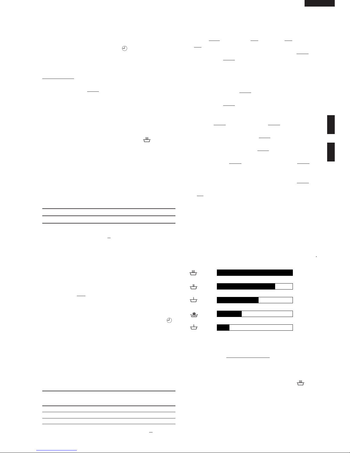
POWER LEVEL COOKING
When the microwave oven is preset for variable cooking
power, rated voltage is supplied to the high voltage transformer intermittently within a 32-second time base through
the relay contact which is coupled with the current-limiting
relay. The following levels of microwave power are given.
SETTING;
NOTE: The ON/OFF time ratio does not exactly corre-
spond to the percentage of microwave power,
because approx. 3 seconds are needed for heating up the magnetron filament.
POWER OUTPUT REDUCTION
1. If the oven is set for more than 20 minutes at 800W,
after the first 20 minutes the power level will automatically adjust itself to 70% power to avoid overcooking.
2. If the oven is operated for more than 90 minutes
continuously (at any power levels), the relay RY1
opens. And the circuit to the high voltage transformer
will be cut off.
32 sec. ON
Approx. 70%
100%
800W
560W
400W
240W
80W
24 sec. ON 8 sec. OFF
14 sec. OFF
10 sec. OFF
26 sec. OFF
Approx. 50%
18 sec. ON
Approx. 30%
12 sec. ON
Approx. 10%
6 sec. ON
R-209(IN)
R-209(W)
R-209(Y)
8
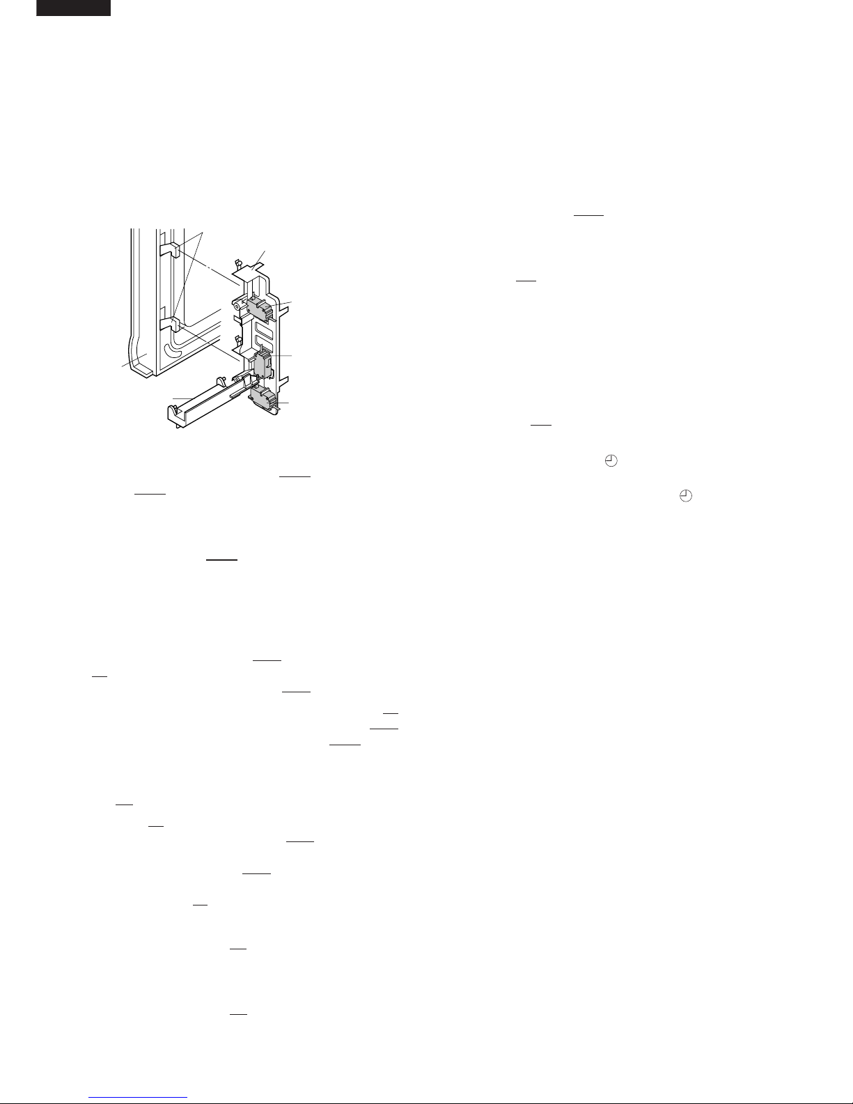
DOOR OPEN MECHANISM
The door is opened by pushing the open button on the
control panel, refer to the Figure D-1.
When the open button is pushed, the open button pushes
up the switch lever, and then the switch lever pushes up
the latch head. The latch heads are moved upward and
released from latch hook. Now the door will open.
Figure D-1. Door Open Mechanism
MONITORED LATCH SWITCH SW1 AND LATCH
SWITCH SW3
1. When the oven door is closed, the contacts (COM-NO)
must be closed.
MONITOR SWITCH SW2
1. When the oven door is closed, the contacts (COM-NC)
must be opened.
2. When the oven door is opened, the contacts (COMNC) must be closed.
3. If the oven door is opened and he contacts (COM-NO)
of the moniored latch switch SW1 fail to open, the fuse
F1 T6.3A blows immediately after closing the contacts
(COM-NC) of the monitor switch SW2.
CAUTION: BEFORE REPLACING A BLOWN FUSE F1
TEST MONITORED LATCH SWITCH SW1
AND MONITOR SWITCH SW2 FOR
PROPER OPERATION. (REFER TO CHAPTER “TEST PROCEDURE”).
FUSE F1 T6.3A
1. The fuse F1 T6.3A blows when the contacts (COMNO) of the monitored latch switch SW1 remain closed
with the oven door open and when the contacts (COMNC) of the monitor switch SW2 are closes.
2. If the wire harness or electrical components are shortcircuited, the fuse F1 T6.3A blows to prevent an electric
shock or fire hazard.
HIGH VOLTAGE FUSE F2
The high voltage fuse blows when the high voltage rectifier
or the magnetron is shorted.
TEMPERATURE FUSE TF
The temperature fuse, located on the top of the oven
cavity, is designed to prevent damage to the oven by fire.
FUNCTION OF IMPORTANT COMPONENTS
If the food load is overcooked, by either error in cook time
or defect in the control unit, the temperature fuse will open.
Under normal operation, the temperature fuse remains
closed. However, when abnormally high temperatures are
reached within the oven cavity, the temperature fuse will
open at 248˚F(120˚C), causing the oven to shut down.
TURNTABLE MOTOR TTM
The turntable motor drives the turntable roller assembly to
rotate the turntable.
FAN MOTOR FM
The fan motor drives a blade which draws external cool air.
This cool air is directed through the air vents surrounding
the magnetron and cools the magnetron. This air is channelled through the oven cavity to remove steam and
vapours given off from heating food. It is then exhausted
through the exhausting air vents at the rear of the oven
cavity.
TIMER MOTOR TM
Timer switch
1. When the timer switch is at " " position, the switch of
the timer is opened.
2. When the timer is turned clockwise from " " position,
the switch of the timer is closed.
NOISE FILTER
The noise filter assembly prevents radio frequency interference that might flow back in the power circuit.
Latch Heads
Latch Hook
Door
SW1:
Monitored
Latch Switch
SW3:
Latch Switch
SW2:
Monitor Switch
Switch Lever
R-209(IN)
R-209(W)
R-209(Y)
9
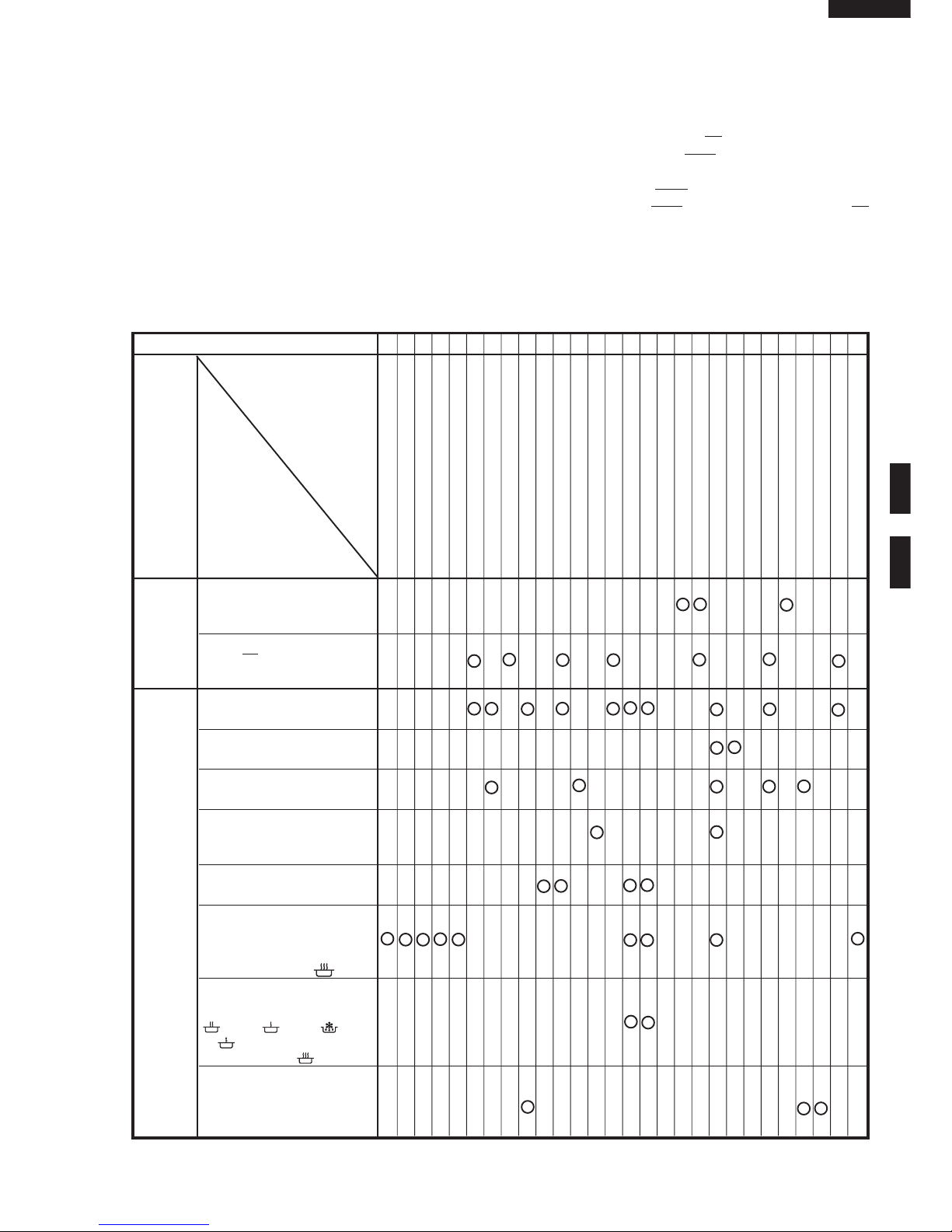
TROUBLESHOOTING GUIDE
When troubleshooting the microwave oven, it is helpful
to follow the Sequence of Operation in performing the
checks. Many of the possible causes of trouble will
require that a specific test be performed. These tests
are given a procedure letter which will be found in the
“Test Procedure” section.
IMPORTANT: If the oven becomes inoperative because
of a blown fuse F1 T6.3A in the monitored
latch switch SW1 - timer switch - monitor
switch circuit, check the monitored latch
switch SW1, timer switch and monitor
switch SW2 before replacing the fuse F1
T6.3A.
CK = Check / RE = Replace
MAGNETRON
HIGH VOLTAGE TRANSFORMER
H.V. RECTIFIER ASSEMBLY
HIGH VOLTAGE WIRE
HIGH VOLTAGE CAPACITOR
MONITORED LATCH SWITCH SW1
LATCH
SWITCH SW3
MONITOR SWITCH SW2
TEMPERATURE FUSE TF
TIMER MOTOR
TIMER SWITCH
FAN MOTOR
TURNTABLE MOTOR
FUSE F1 T6.3A
CONTROL UNIT
RELAY (RY-1)
FOIL PATERN ON P.W.B.
POWER SUPPLY CORD
SHORTED WIRE HARNESS
OPENED WIRE HARNESS
OVEN LAMP
WALL OUTLET
MISADJUSTMENT SWITCH
HOME FUSE OR BREAKER
BLOCKED COOLING FAN
BLOCKED VENTILATION
NOISE FILTER
H.V. FUSE F2
Home fuse blows when power
supply cord is plugged into
wall outlet.
FUSE
F1 T6.3A blows when
power supply cord is plugged
into wall outlet.
Oven does not start when the
timer is set.
Oven lamp does not light
(Other function is normal.)
Fan motor does not operate.
(Other function is normal.)
Turntable motor does not operate. (Other function is normal.)
Oven or any electrical parts
does not stop.
Oven seems to be operating
but little or no heat is produced
in oven load. (Microwave
power level is set at 800W)
Oven does not seems to be
operating properly when
560W, 400W, 240W
or 80W is set. (Oven operates properly at 800W.)
Oven goes into cook cycle but
shuts down before end of cooking cycle.
OFF
CONDITION
PROBLEM
CONDITION
POSSIBLE CAUSE
AND
DEFECTIVE PARTS
TEST PROCEDURE
ON
CONDITION
ABC
CK D
EEE FK K I I G LMNRECKCKRECK CKCKCK CK HJ
 Loading...