


2100W/R-25JT
R-25JT-F


 SERVICE MANUAL
S0513R25JTF//
COMMERCIAL
MICROWAVE OVEN
MODEL R-25JT-F
DOUBLE |
|
EXPRESS |
|
QUANTITY |
DEFROST |
||
|
|
11 |
1 |
|
|
12 |
2 |
|
|
|
|
|
|
13 |
3 |
|
|
14 |
4 |
|
|
15 |
5 |
|
|
16 |
6 |
|
|
17 |
7 |
|
|
18 |
8 |
|
|
19 |
9 |
|
|
20 |
0 |
SELECTATIME |
STOP/CLEAR |
||
SELECTAPOWER |
START |
||
SET |
CHECK SIGNAL |
||
|
|||
In the interest of user-safety the oven should be restored to its original condition and only parts identical to those specified should be used.
WARNING TO SERVICE PERSONNEL: Microwave ovens contain circuitry capable of producing very high voltage and current, contact with following parts may result in a severe, possibly fatal, electrical shock. (High Voltage Capacitor, High Voltage Power Transformer, Magnetron, High Voltage Rectifier Assembly, High Voltage Harness etc..)
TABLE OF CONTENTS |
|
|
Page |
PRECAUTIONS TO BE OBSERVED BEFORE AND DURING SERVICE TO |
|
AVOID POSSIBLE EXPOSURE TO EXCESSIVE MICROWAVE ENERGY ................... |
INSIDE FRONT COVER |
BEFORE SERVICING ...................................................................................................... |
INSIDE FRONT COVER |
WARNING TO SERVICE PERSONEL .................................................................................................................. |
1 |
MICROWAVE MEASUREMENT PROCEDURE ................................................................................................... |
2 |
FOREWORD .......................................................................................................................................................... |
3 |
PRODUCT SPECIFICATIONS .............................................................................................................................. |
4 |
GENERAL INFORMATION ................................................................................................................................... |
4 |
OPERATION .......................................................................................................................................................... |
6 |
TROUBLE SHOOTING GUIDE/ TEST PROCEDURE ........................................................................................ |
11 |
TOUCH CONTROL PANEL ................................................................................................................................. |
21 |
COMPONENT REPLACEMENT AND ADJUSTMENT PROCEDURE ................................................................ |
31 |
PICTORIAL DIAGRAM ........................................................................................................................................ |
37 |
CONTROL PANEL CIRCUIT ............................................................................................................................... |
38 |
PRINTED WIRING BOARD ................................................................................................................................. |
39 |
PARTS LIST ........................................................................................................................................................ |
40 |
PACKING AND ACCESSORIES ......................................................................................................................... |
45 |
SHARP CORPORATION
This document has been published to be used for after sales service only.
The contents are subject to change without notice.

R-25JT-F
PRECAUTIONS TO BE OBSERVED BEFORE AND DURING SERVICING TO AVOID POSSIBLE EXPOSURE TO EXCESSIVE MICROWAVE ENERGY
(a)Do not operate or allow the oven to be operated with the door open.
(b)Make the following safety checks on all ovens to be serviced before activating the magnetron or other microwave source, and make repairs as necessary: (1) interlock operation, (2) proper door closing, (3) seal and sealing surfaces (arcing, wear, and other damage), (4) damage to or loosening of hinges and latches, (5) evidence of dropping or abuse.
(c)Before turning on microwave power for any service test or inspection within the microwave generating compartments, check the magnetron, wave guide or transmission line, and cavity for proper alignment, integrity, and connections.
(d)Any defective or misadjusted components in the interlock, monitor, door seal, and microwave generation and transmission systems shall be repaired, replaced, or adjusted by procedures described in this manual before the oven is released to the owner.
(e)A microwave leakage check to verify compliance with the Federal Performance Standard should be performed on each oven prior to release to the owner.
BEFORE SERVICING
Before servicing an operative unit, perform a microwave emission check as per the Microwave Measurement Procedure outlined in this service manual.
If microwave emissions level is in excess of the specified limit, contact SHARP ELECTRONICS CORPORATION immediately @1-800-237-4277.
If the unit operates with the door open, service person should 1) tell the user not to operate the oven and 2) contact SHARP ELECTRONICS CORPORATION and the Food and Drug Administration's Center for Devices and Radiological Health immediately.
Service personnel should inform SHARP ELECTRONICS CORPORATION of any certified unit found with emissions in excess of 4mW/cm2. The owner of the unit should be instructed not to use the unit until the oven has been brought into compliance.

R-25JT-F
WARNING TO SERVICE PERSONNEL
Microwave ovens contain circuitry capable of producing very high voltage and current, contact with following parts may result in a severe, possibly fatal, electrical shock.
(Example)
High Voltage Capacitor, High Voltage Power Transformer, Magnetron, High Voltage Rectifier Assembly, High Voltage Harness etc..
Read the Service Manual carefully and follow all
instructions.
Don't Touch ! Danger High Voltage
Before Servicing
1.Disconnect the power supply cord , 
 and then remove outer case.
2.Open the door and block it open.
3.Discharge two high voltage capacitors.
WARNING: RISK OF ELECTRIC SHOCK. DISCHARGE THE TWO HIGH VOLTAGE CAPACITORS BEFORE SERVICING.
The high-voltage capacitors remain charged about 60 seconds after the oven has been switched off. Wait for 60 seconds and then short-circuit the connection of the highvoltage capacitors (that are the connecting lead of the highvoltage rectifiers) against the chassis with the use of an insulated screwdriver.
Whenever troubleshooting is performed the power supply must be disconnected. It may, in some cases, be necessary to connect the power supply after the outer case has been removed, in this event,
1.Disconnect the power supply cord, and then remove outer case.
2.Open the door and block it open.
3.Discharge two high voltage capacitors.
4.Disconnect the leads to the primary of the power transformer.
5.Ensure that the leads remain isolated from other components and oven chassis by using insulation tape.
6.After that procedure, reconnect the power supply cord.
When the testing is completed,
1.Disconnect the power supply cord, and then remove outer case.
2.Open the door and block it open.
3.Discharge two high voltage capacitors.
4.Reconnect the leads to the primary of the power transformer.
5.Reinstall the outer case (cabinet).
6.Reconnect the power supply cord after the outer case is installed.
7.Run the oven and check all functions.
After repairing
1.Reconnect all leads removed from components during testing.
2.Reinstall the outer case (cabinet).
3.Reconnect the power supply cord after the outer case is installed.
4.Run the oven and check all functions.
Microwave ovens should not be run empty. To test for the presence of microwave energy within a cavity, place a cup of cold water on the oven turntable, close the door and set the power to HIGH and set the microwave timer for two (2) minutes. When the two minutes has elapsed (timer at zero) carefully check that the water is now hot. If the water remains cold carry out Before Servicing procedure and re-examine the connections to the component being tested.
When all service work is completed and the oven is fully assembled, the microwave power output should be checked and microwave leakage test should be carried out.
1

R-25JT-F
MICROWAVE MEASUREMENT PROCEDURE
A. Requirements:
1)Microwave leakage limit (Power density limit): The power density of microwave radiation emitted by a microwave oven should not exceed 1mW/cm2 at any point 5cm or more from the external surface of the oven, measured prior to acquisition by a purchaser, and thereafter (through the useful life of the oven), 5 mW/cm2 at any point 5cm or more from the external surface of the oven.
2)Safety interlock switches: Primary interlock relay and door sensing switch shall prevent microwave radiation emission in excess of the requirement as above mentioned, secondary interlock switch shall prevent microwave radiation emission in excess of 5 mW/cm2 at any point 5cm or more from the external surface of the oven.
B. Preparation for testing:
Before beginning the actual measurement of leakage, proceed as follows:
1)Make sure that the actual instrument is operating normally as specified in its instruction booklet.
Important:
Survey instruments that comply with the requirement for instrumentation as prescribed by the performance standard for microwave ovens, 21 CFR 1030.10(c)(3)(i), must be used for testing.
2)Place the oven tray in the oven cavity.
3)Place the load of 275±15 ml (9.8 oz) of tap water initially at 20±5˚C (68˚F) in the center of the oven cavity.
The water container shall be a low form of 600 ml (20 oz) beaker with an inside diameter of approx. 8.5 cm (3-1/2 in.) and made of an electrically nonconductive material such as glass or plastic.
The placing of this standard load in the oven is important not only to protect the oven, but also to insure that any leakage is measured accurately.
4)Set the cooking control on Full Power Cooking Mode
5)Close the door and select a cook cycle of several minutes. If the water begins to boil before the survey is completed, replace it with 275 ml of cool water.
C.Leakage test:
Closed-door leakage test (microwave measurement)
1)Grasp the probe of the survey instrument and hold it perpendicular to the gap between the door and the body of the oven.
2)Move the probe slowly, not faster than 1 in./sec. (2.5 cm/sec.) along the gap, watching for the maximum indication on the meter.
3)Check for leakage at the door screen, sheet metal seams and other accessible positions where the continuity of the metal has been breached (eg., around the switches, indicator, and vents).
While testing for leakage around the door pull the door away from the front of the oven as far as is permitted by the closed latch assembly.
4)Measure carefully at the point of highest leakage and make sure that the highest leakage is no greater than 4mW/cm2, and that the secondary interlock switch does turn the oven OFF before any door movement.
NOTE: After servicing, record data on service invoice and microwave leakage report.
2

SERVICE MANUAL
COMMERCIAL
MICROWAVE OVEN
R-25JT-F
FOREWORD
This Manual has been prepared to provide Sharp Electronics Corp. Service Personnel with Operation and Service Information for the SHARP MICROWAVE OVENS, R-25JT-F.
It is recommended that service personnel carefully study the entire text of this manual so that they will be qualified to render satisfactory customer service.
Check the interlock switches and the door seal carefully. Special attention should be given to avoid electrical shock and microwave radiation hazard.
WARNING
Never operate the oven until the following points are ensured.
(A)The door is tightly closed.
(B)The door brackets and hinges are not defective.
(C)The door packing is not damaged.
(D)The door is not deformed or warped.
(E)There is no other visible damage with the oven.
Servicing and repair work must be carried out only by trained service personnel.
DANGER
Certain initial parts are intentionally not grounded and present a risk of electrical shock only during servicing. Service personnel - Do not contact the following parts while the appliance is energized;
High Voltage Capacitor, Power Transformer, Magnetron, High Voltage Rectifier Assembly, High Voltage Harness;
If provided, Vent Hood, Fan assembly, Cooling Fan Motor.
All the parts marked “*” on parts list are used at voltages more than 250V.
Removal of the outer wrap gives access to voltage above 250V.
All the parts marked “∆” on parts list may cause undue microwave exposure, by themselves, or when they are damaged, loosened or removed.
SHARP ELECTRONICS CORPORATION
SHARP PLAZA, MAHWAH,
NEW JERSEY 07430-2135
R-25JT-F
PRODUCT DESCRIPTION
GENERAL INFORMATION
OPERATION
TROUBLESHOOTING GUIDE AND TEST PROCEDURE
TOUCH CONTROL PANEL
COMPONENT REPLACEMENT AND ADJUSTMENT PROCEDURE
WIRING DIAGRAM
PARTS LIST
3

R-25JT-F
|
SPECIFICATION |
|
|
|
|
|
|
ITEM |
|
DESCRIPTION |
|
|
|
|
|
Power Requirements |
230/208 Volts 3.2 kW |
|
|
|
Approx. 15.5 A at 208 V / Approx. 14.5 A at 230 V |
||
|
60 Hertz / Single phase, 3 wire grounded |
|
|
|
|
||
Power Output |
2100 watts (IEC 705 Test Procedure) Operating frequency of 2450MHz |
||
|
|
|
|
Case Dimensions |
Width 20-1/8" (510mm) Height 13-1/4" (335mm) |
Depth 18-1/2" (470mm) |
|
|
|
|
|
Cooking Cavity Dimensions |
Width 13" (330mm) |
Height 7-1/8" (180mm) |
Depth 13" (330mm) |
|
|
|
|
Control Complement |
Touch Control System |
|
|
|
Digital Display |
|
|
|
10 Number Pads |
|
|
|
STOP/CLEAR pad |
|
|
|
START pad |
|
|
|
SELECTAPOWER pad (Power level: 0 to 100%) |
|
|
|
SELECTATIME pad |
|
|
|
DOUBLE QUANTITY pad |
|
|
|
EXPRESS DEFROST pad |
|
|
|
Memory SET pad |
|
|
|
Memory CHECK pad |
|
|
|
SIGNAL pad |
|
|
|
|
|
|
Weight |
Approx. 68 lbs/ 31 kg |
|
|
|
|
|
|
Safety Standard |
UL Listed |
FCC Authorized |
|
|
DHHS Rules, CFR, Title 21, Chapter 1, Subchapter J |
||
|
NSF Certified |
|
|
|
|
|
|
GENERAL INFORMATION
GROUNDING INSTRUCTIONS
This appliance must be grounded. In the event of an electrical short circuit, grounding reduces the risk of electric shock by providing an escape wire for the electric current. This appliance is equipped with a cord having a grounding wire with a grounding plug. The plug must be plugged into an outlet that is properly installed and grounded.
WARNING: Improper use of the grounding plug can result in a risk of electric shock. The electrical requirements are 230/208 Volt, 60 Hz, AC only, and 20 Amp or more fused electrical supply. It is recommended that a separate circuit serving only this appliance be provided. When installing this appliance, observe all applicable
codes and ordinances. If it is necessary to use an extension cord, use only a 3-wire extension cord that has a 3-blade grounding plug and a 3-slot receptacle that will accept the plug on the appliance. The marked rating of the extension cord should be AC 230/208 Volt 20 Amp.
VOLTAGE SELECT
The oven has been preset for 230V operation.
If you need to change this oven for 208V operation, follow instructions below.
1.Unplug oven.
2.Remove one screw(A) from the Voltage Select Cover located on back of the oven near the bottom.
3.Remove the Voltage Select Cover and rotate 180 degrees.
4.Reinstall the Voltage Select Cover using one screw(A) removed in Step 2.
5.Plug power cord into wall outlet.
Your oven is now ready for 208V, 60Hz operation.
Note: If “EE4” or “EE5” appears in the lighted digital display, a voltage adjustment must be made.
Power supply cord 
208 V
230 V (A) |
208 V |
230 V |
4
R-25JT-F
|
|
|
OVEN DIAGRAM |
|
|
||
10 |
9 |
5 |
4 |
3 |
2 |
16 |
|
|
|
|
|
|
17 |
|
|
|
|
|
|
|
1 |
|
13 |
|
|
|
|
|
|
|
|
12 |
|
|
|
|
|
15 |
14 |
|
|
|
|
|
|
||
|
|
|
|
18 |
|
|
|
|
|
|
|
|
|
|
|
11 |
|
8 |
|
7 |
6 |
|
|
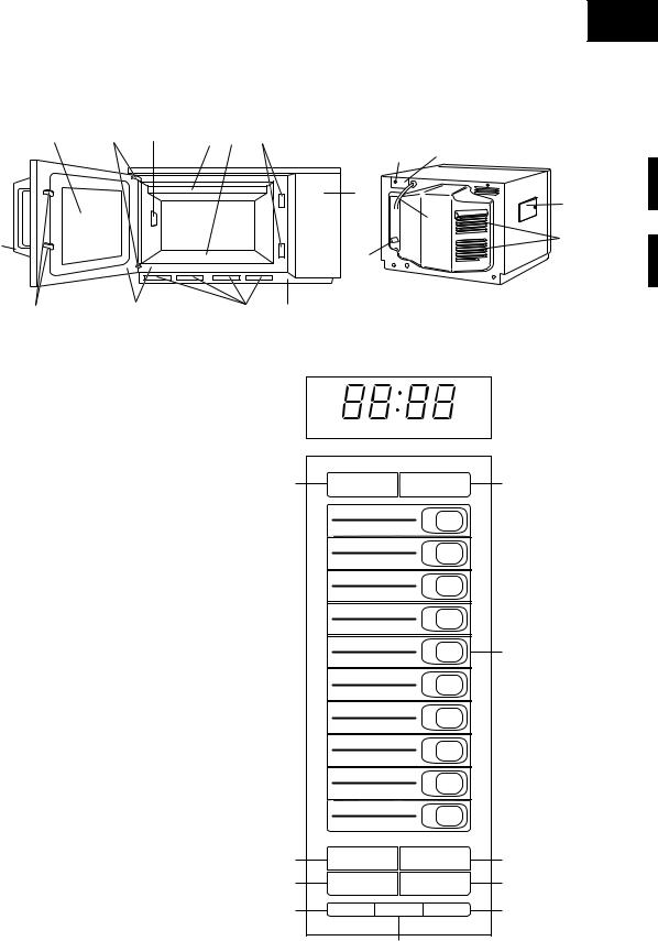
1.Touch control panel
2.Door latch openings
3.Ceramic shelf
4.Splash cover
5.Oven light
6.Air intake filter
7.Air intake openings
8.Door seals and sealing surfaces
9.Door hinges
10.Oven door with see-through window
11.Door latches
12.Door handle
13.Service window for replacing the oven light bulb.
14.Ventilation openings
15.Power supply cord
16.Mounting plate
17.Screw for mouning plate
18.Voltage select cover
Control Panel
19.DOUBLE QUANTITY pad
20.EXPRESS DEFROST pad
21.Ten number pads for time and memory programming
22.SELECTATIME pad
23.STOP/CLEAR pad; touch to stop operation of oven and clear remaining heating time
24.SELECTAPOWER pad for setting variable power level
25.START pad; touch to operate oven after door is closed and time is set
26.SET pad for setting memory
27.CHECK pad for checking memory
28.SIGNAL pad for setting signal sound
|
ON |
DEF NO. X2 |
CHECK |
|
||
19 |
DOUBLE |
EXPRESS |
20 |
|||
|
QUANTITY |
DEFROST |
|
|||
|
|
|
|
11 |
1 |
|
|
|
|
|
12 |
2 |
|
|
|
|
|
13 |
3 |
|
|
|
|
|
14 |
4 |
|
|
|
|
|
15 |
5 |
21 |
|
|
|
|
16 |
6 |
|
|
|
|
|
17 |
7 |
|
|
|
|
|
18 |
8 |
|
|
|
|
|
19 |
9 |
|
|
|
|
|
20 |
0 |
|
22 |
SELECTATIME |
STOP/CLEAR |
23 |
|||
24 |
SELECTAPOWER |
START |
25 |
|||
26 |
SET |
CHECK |
SIGNAL |
28 |
||
27
5

R-25JT-F
OPERATION
DESCRIPTION OF OPERATING SEQUENCE
The following is a description of component functions during oven operation.
OFF CONDITION
Closing the door activates the door sensing switch and secondary interlock switches (1), (2). (In this condition, the monitor switches (1) & (2) contacts are opened.) When the oven is plugged in, and the rated voltage is supplied to the control unit through the noise filter, (figure O-1), the display will show " . ".
IDLE CONDITION
When the door is opened, the contacts of the door sensing switch open, initiating the following:
1.A signal is input to the control unit energizing the coil of shutoff relay (RY-1).
2.The shut-off relay (RY-1) contacts close completing circuits to turn on the oven lamp, blower motor and stirrer motors.
3.If the door remains open, 60 seconds later the control unit de-energizes shut-off relay (RY-1) turning off the oven lamp, blower motor and stirrer motors.
When the door is closed, the door sensing switch contacts close. With the closing of the door sensing switch contacts, an additional circuit is provided which will permit the operation of the oven when one of the touch pads is depressed. Since the control is enabled through the door sensing switch, the door must be closed before the touch pads will be effective. When the door is closed, a full 60 second IDLE condition is always provided for selecting and pressing the desired touch pads. A 60 second IDLE condition will also follow the end of each cook cycle.
COOKING CONDITION
When the door is closed from the open position and Memory pad is touched the, following will occur:
1.The contacts of relays are closed and components connected to the relays are turned on (For details, refer to Figure O-3)
2.Rated voltage is supplied to the primary winding of the power transformer and is converted to about 3.15 volts output on the filament winding, and approximately 2305 volts on the high voltage winding.
3.The filament winding voltage heats the magnetron filament and the H.V. winding voltage is sent to a voltage doubler circuit.
4.The microwave energy produced by the magnetron is channelled through the waveguide into the cavity feed-box, and then into the cavity where the food is placed to be cooked.
5.Upon completion of the cooking time, the oven will revert to the IDLE condition.
6.When the door is opened during a cook cycle, monitor switches (1) & (2), door sensing switch, secondary interlock switches (1), (2) and primary interlock relays (1), (2) are activated with the following results. The circuits to the high voltage components are de-energized, and the digital readout displays " . " and cooking is cancelled (in the case of Memory cooking).
7.The monitor switch (1) is electrically monitoring the operation of the secondary interlock switch (1) and primary interlock relay (1), and monitor switch (2) is electrically monitoring the operation of the secondary interlock switch (2) and primary interlock relay (2), and monitor switches (1), (2) are
mechanically associated with the door so that it will function in the following sequence.
(1)When the door opens from a closed position, the contacts of the primary interlock relays (1), (2) and secondary interlock switches (1), (2) open. Then the monitor switch contacts close.
(2)When the door is closed from the open position, the monitor switches (1), (2) contacts first open, and then the contacts of the secondary interlock switches (1), (2) close.
If the secondary interlock switches (1), (2) and primary interlock relays (1), (2) fail with their contacts closed when the door is opened, the closing of the monitor switches (1), (2) contacts will form a short circuit through the monitor fuse, secondary interlock switches (1), (2) and primary interlock relays (1), (2), causing the monitor fuse to blow.
VARIABLE POWER COOKING
When Variable Cooking Power is programmed, the rated voltage A.C. is supplied to the power transformer intermittently through the contacts of relay (RY-2, RY-3). Relays RY-2 and RY-3 are operated by the control unit within an interval second time base. Microwave power operation is as follows:
POWER LEVEL |
ON TIME |
OFF TIME |
100% |
32 sec. |
0 sec. |
|
|
|
90% |
30 sec. |
2 sec. |
|
|
|
80 % |
26 sec. |
6 sec. |
|
|
|
70% |
24 sec. |
8 sec. |
|
|
|
60% |
22 sec. |
10 sec. |
|
|
|
50% |
18 sec. |
14 sec. |
|
|
|
40% |
16 sec. |
16 sec. |
|
|
|
30% |
12 sec. |
20 sec. |
|
|
|
20% |
8 sec. |
24 sec. |
10% |
6 sec. |
26 sec. |
0% |
0 sec. |
32 sec. |
Note: The ON/OFF time ratio does not exactly correspond with the percentage of microwave power, because approx. 2 seconds are needed for heating of the magnetron filament.
6
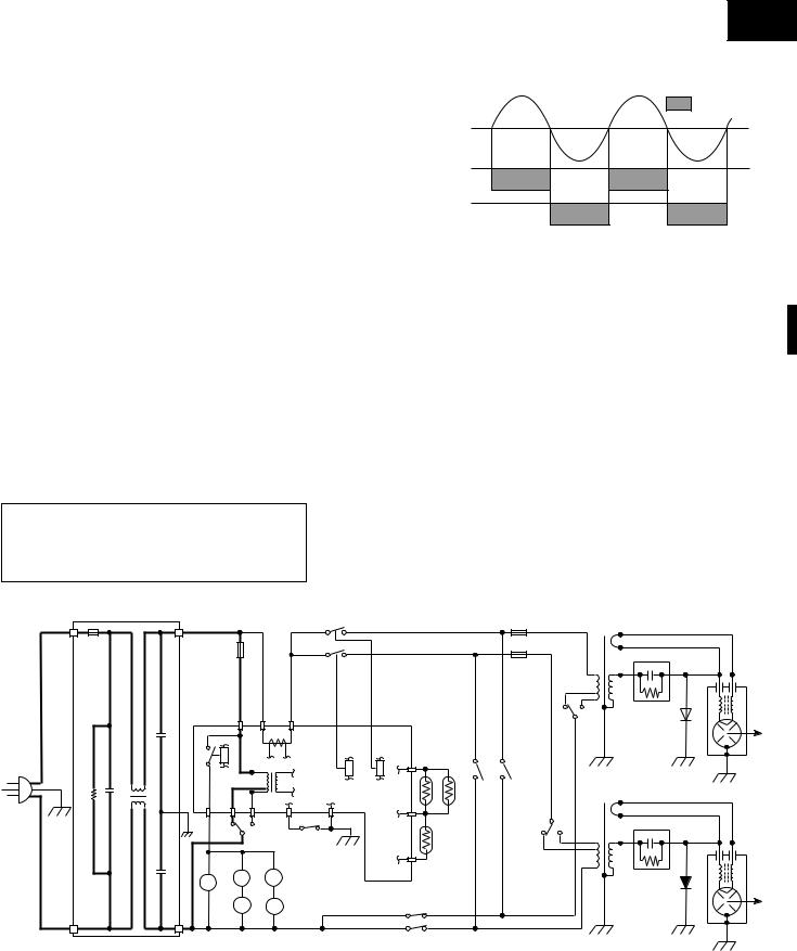
TWO MAGNETRON OPERATION SYSTEM
Two magnetrons (1), (2) are equipped in order to get higher microwave power output. The primary windings of the power transformers (1), (2) are connected so that each magnetron can be oscillated alternatively according to the frequency of the power supply. Refer to the Figure B-1.
COMMERCIAL FREQUENCY (60HZ)
POWER OUTPUT BY MAGNETRON 1
POWER OUTPUT BY MAGNETRON 2
R-25JT-F
OPERATION OF MAGNETRON
Figure B-1. Operation of Magnetron
SCHEMATIC
NOTE: CONDITION OF OVEN
1.DOOR CLOSED OR 1 MINUTE AFTER COOK OFF
2." . " APPEARS ON DISPLAY
|
|
NOISE |
|
|
|
|
FILTER |
|
|
|
FUSE 20A |
|
|
|
|
BLK |
CROSSLINECAPACITOR 1.0 F AC250V |
NOISESUPPRESSION COIL |
|
208/230V 60Hz |
DISCHARGERESISTOR 470K 1/2W |
3300pF |
||
|
GRN |
|
|
|
|
WHT |
|
|
|
|
|
|
|
3300pF |
|
|
|
|
|
PRIMARY |
|
|
|
|
|
MAGNETRON |
|
||
|
|
|
|
|
INTERLOCK |
|
|
|
|
|
|
|||
|
|
|
|
|
|
|
|
|
|
TEMP. FUSE (1) |
|
|||
|
|
|
|
|
RELAY (1) |
|
|
|
|
|
|
|||
|
|
|
|
|
|
|
|
|
|
|
|
|
||
|
|
|
|
|
|
|
|
|
|
|
|
|
MAGNETRON |
|
OVEN |
|
|
|
|
|
|
|
|
|
|
|
TEMP. FUSE (2) |
||
TEMP. |
|
|
|
|
|
|
|
|
|
|
|
|
|
|
FUSE |
|
|
|
PRIMARY |
|
|
|
|
|
|
|
|
||
|
|
|
|
|
INTERLOCK |
|
|
|
|
|
|
|
|
|
|
|
|
|
|
RELAY (2) |
|
|
|
|
|
|
|
|
|
|
|
|
|
|
TAB2 |
|
|
|
|
|
|
|
|
NC |
|
|
|
|
|
|
|
|
(2) |
|
|
|
|
VOLTAGESELECT (V.S.SW)SWITCH (2) |
|
|
RY1 |
|
TAB1 |
|
|
RY3 |
RY2 |
H3 H1 |
OVEN THERMISTOR |
THERMISTOR MAGNETRON |
(2) SWITCH MONITOR |
(1) SWITCH MONITOR |
(3) |
COM |
|
A7 |
|
|
|
|
|
|
|
|
|
|
|
|
|
A1 |
A5 |
A3 |
|
|
B2 |
B1 |
|
|
|
|
|
|
|
COM |
|
|
|
|
OL |
|
|
|
|
OVEN (1)THERMISTOR |
|
|
|
V.S.SW |
|
|
V.S. |
|
NC |
DOOR SENSING |
|
B3 |
|
|
|
NC |
||||
|
SW (1) |
COM |
|
|
|
|
|
|
|
|
|
|||
|
|
|
SWITCH |
|
|
|
|
|
|
|
|
|
||
BM |
BLOWERMOTOR |
SM SM |
STIRRERMOTOR |
OL |
OVENLAMP |
|
SECONDARY INTERLOCK |
|
|
|
|
|
||
|
|
|
|
|
|
|
SWITCHE(1) |
|
|
|
|
|
|
|
SECONDARY INTERLOCK
SWITCHE(2)
Figure O-1. Oven Schematic-OFF Condition (208 V Condition)
POWER TRANSFORMER (1)
CAPACITOR (1)  (1)RECTIFIER 0.94µF
H.V.
POWER TRANSFORMER (2)
|
(2) |
0.94µF |
RECTIFIER |
CAPACITOR (2) |
|
|
H.V. |
MAGNETRON (1)
MAGNETRON (2)
7

R-25JT-F
SCHEMATIC
NOTE: CONDITION OF OVEN
1.FOR 1MINUTE AFTER DOOR OPENED.
2." . " APPEARS ON DISPLAY.
|
|
NOISE |
|
|
|
|
FILTER |
|
|
|
FUSE 20A |
|
|
|
|
BLK |
CROSSLINECAPACITOR 1.0 F AC250V |
NOISESUPPRESSION COIL |
|
208/230V 60Hz |
DISCHARGERESISTOR 470K 1/2W |
3300pF |
||
|
GRN |
|
|
|
|
WHT |
|
|
|
|
|
|
|
3300pF |
|
|
|
|
|
PRIMARY |
|
|
|
|
|
|
|
|
|
|
INTERLOCK |
|
|
|
|
|
|
|
|
|
|
RELAY (1) |
|
|
|
|
|
OVEN |
|
|
|
|
|
|
|
|
|
|
TEMP. |
|
|
|
|
|
|
|
|
|
|
FUSE |
|
|
|
PRIMARY |
|
|
|
|
||
|
|
|
|
|
INTERLOCK |
|
|
|
|
|
|
|
|
|
|
RELAY (2) |
|
|
|
|
|
|
RY1 |
|
TAB1 |
|
TAB2 |
RY3 |
RY2 |
H1 |
(2) |
THERMISTOR |
|
|
|
OVEN THERMISTOR |
|||||||
|
A7 |
|
|
|
|
|
|
|
|
|
A1 |
A5 |
A3 |
|
B2 |
B1 |
|
H3 |
|
MAGNETRON |
|
|
V.S. |
|
NC |
|
|
|
|
|
|
(1) |
|
SW (1) |
|
|
|
DOOR SENSING |
|
|
|
||
|
|
COM |
OL |
|
B3 |
|
OVEN THERMISTOR |
|||
|
|
|
SWITCH |
|
|
|
||||
|
|
|
|
|
|
|
|
|
||
BM |
BLOWERMOTOR |
SM SM |
STIRRERMOTOR |
OL |
OVENLAMP |
|
SECONDARY INTERLOCK |
|||
|
|
|
|
|
|
|
SWITCHE(1) |
|
|
|
|
|
|
|
|
|
|
SECONDARY INTERLOCK |
|||
|
|
|
|
|
|
|
SWITCHE(2) |
|
|
|
MAGNETRON
TEMP. FUSE (1)
MAGNETRON
TEMP. FUSE (2)
MONITOR SWITCH (2) |
MONITOR SWITCH (1) |
|
VOLTAGE SELECT SWITCH (V.S.SW) (2) |
|
|
(3) |
COM |
|
|
|
|
|
|
V.S.SW |
NC |
NC
COM
Figure O-2. Oven Schematic-IDLE Condition (208 V Condition)
POWER TRANSFORMER (1)
CAPACITOR (1)  (1)RECTIFIER 0.94µF
H.V.
POWER TRANSFORMER (2)
|
(2) |
0.94µF |
RECTIFIER |
CAPACITOR (2) |
|
|
H.V. |
MAGNETRON (1)
MAGNETRON (2)
SCHEMATIC NOTE: CONDITION OF OVEN
1.DOOR CLOSED.
2.SELECTATIME PAD TOUCHED.
3.COOKING TIME PROGRAMMED.
4.START PAD TOUCHED.
BLK
208/230V 60Hz
GRN
WHT
NOISE
FILTER
FUSE 20A
DISCHARGE RESISTOR 470K 1/2W |
LINE CROSS CAPACITOR 1.0 F AC250V |
NOISE SUPPRESSION COIL |
3300pF |
|
|
|
3300pF |
|
PRIMARY |
MAGNETRON |
|
INTERLOCK |
|
|
TEMP. FUSE (1) |
|
|
RELAY (1) |
|
|
|
|
|
|
MAGNETRON |
OVEN |
|
TEMP. FUSE (2) |
TEMP. |
|
|
FUSE |
PRIMARY |
|
|
INTERLOCK |
|
|
RELAY (2) |
|
|
|
|
|
|
TAB2 |
|
|
|
|
|
|
|
VOLTAGESELECT |
NC |
|
|
|
|
|
|
|
|
(2) |
|
|
|
(V.S.SW)SWITCH (2) |
||
|
RY1 |
|
TAB1 |
|
|
RY3 |
RY2 |
H3 H1 |
OVEN THERMISTOR |
THERMISTOR MAGNETRON |
(2) SWITCH MONITOR |
(1) SWITCH MONITOR |
(3) |
COM |
|
A7 |
|
|
|
|
|
|
|
|
|
|
|
|
|
A1 |
A5 |
A3 |
|
|
B2 |
B1 |
|
|
|
|
|
|
COM |
|
|
|
|
|
OL |
|
|
|
|
OVEN (1)THERMISTOR |
|
|
|
||
|
V.S. |
|
NC |
DOOR SENSING |
|
B3 |
|
|
|
V.S.SW |
NC |
|||
|
SW (1) |
COM |
|
|
|
|
|
|
|
|
|
|||
|
|
|
SWITCH |
|
|
|
|
|
|
|
|
|
||
BM |
BLOWERMOTOR |
SM SM |
STIRRERMOTOR |
OL |
OVENLAMP |
|
SECONDARY INTERLOCK |
|
|
|
|
|
||
|
|
|
|
|
|
|
SWITCHE(1) |
|
|
|
|
|
|
|
|
|
|
|
|
|
|
SECONDARY INTERLOCK |
|
|
|
|
|
||
|
|
|
|
|
|
|
SWITCHE(2) |
|
|
|
|
|
|
|
Figure O-3. Schematic-Cooking Condition (208 V Condition)
POWER TRANSFORMER (1)
|
(1) |
CAPACITOR (1) |
RECTIFIERH.V. |
0.94µF |
|
POWER |
|
TRANSFORMER (2) |
|
|
(2) |
0.94µF |
RECTIFIER |
CAPACITOR (2) |
|
|
H.V. |
MAGNETRON (1)
MAGNETRON (2)
8
R-25JT-F
DESCRIPTION AND FUNCTION OF COMPONENTS
DOOR OPEN MECHANISM
1.The door release lever is pulled.
2.The upper latch head is lifted up by the linked door release lever.
3.The latch lever is lifted up by the door release lever.
4.The joint lever is lifted up by the latch lever.
5.The lower latch head is lifted up by the joint lever.
6.Now both latch heads are lifted up, so they can be released from the latch hook.
7.Now the door can be opened.
Door release lever
Joint lever
Latch lever
Latch head
Latch head
Switch lever A
Monitor switch (2)
Monitor switch (1)
 Latch hook
Switch lever B
 Secondary interlock
switch (2)
 Secondary interlock
  switch (1)
 Door sensing switch
Switch lever C
Figure D-1. Door Open Mechanism
DOOR SENSING SWITCH
The door sensing switch is activated by the latch head of the door and switch lever C. When the door is opened, the contacts of the switch open and interrupt the circuit to the coils of the primary interlock relays (1), (2). The contacts of the primary relays (1), (2) then open and interrupt the circuit to the primary winding of the power transformers. At this time, the contacts of relay RY1 close and the blower motor, stirrer motors and oven lamps are energized for 1 minute.
Functions:
With the door shut, the contacts of the door sensing switch and the secondary interlock switches (1), (2) are closed and the contacts of the monitor switches (1), (2) are open.
1.When the door is opened, the contact of the door sensing switch and secondary interlock switches (1), (2) are opened first, then the contact of the monitor switches (1), (2) are closed.
2.As the door goes to a closed position, the contacts of the monitor switches (1), (2) are opened first, then the contacts of the door sensing switch and the secondary interlock switches (1), (2) close.
3.If the door is opened, and the contacts of the primary interlock relay and secondary interlock switch of the same circuit fail to open, the monitor fuse blows simultaneously with closing of the monitor switch contacts of that circuit (1 or 2).
CAUTION: BEFORE REPLACING A BLOWN MONITOR FUSE TEST THE DOOR SENSING SWITCH, PRIMARY INTERLOCK RELAYS (1), (2), SECONDARY INTERLOCK SWITCHES (1), (2) AND MONITOR SWITCHES (1), (2) FOR PROPER OPERATION. (REFER TO CHAPTER "TEST PROCEDURE").
NOTE: MONITOR FUSE AND SWITCH ARE REPLACED AS AN ASSEMBLY.
MAGNETRON TEMPERATURE FUSES (1), (2)
The temperature fuses (1), (2) located on the top of the upper and lower waveguide, are designed to prevent damage to the magnetrons (1), (2). If an over heated condition develops in the tube due to blower motor failure, obstructed air ducts, dirty or blocked air intake, etc., the circuit to the magnetrons are interrupted. Under normal operation, the temperature fuses remains closed. However, when abnormally high temperatures are generated within the magnetron, the temperature fuse will open at 302˚F (150˚C) causing the microwave energy to stop. The defective temperature fuse must be replaced with new rated one.
SECONDARY INTERLOCK SWITCHES (1), (2)
The secondary interlock switches (1), (2) are activated by the upper latch head of the door and switch lever B. When the door is opened, the contacts of the switch open and interrupt the circuit to the primary winding of the power transformers (1), (2).
MONITOR SWITCHES (1), (2)
The monitor switches (1), (2) are mounted in the upper position of the latch hook. The monitor switches are activated by the upper latch head of the door and switch lever A. When the door is opened, the contacts of the monitor switches close. Monitor switch (1) is intended to render the oven inoperative by means of blowing the monitor fuse, when the contacts of the primary interlock relay (1) and secondary interlock switch (1) fail to open when the door is opened. Monitor switch (2) is intended to render the oven inoperative by means of blowing the monitor fuse, when the contacts of the primary interlock relay (2) and secondary interlock switch (2) fail to open when the door is opened.
OVEN TEMPERATURE FUSE
The temperature fuse, located on the side of the exhaust duct assembly, is designed to prevent damage to the oven by fire. If the food load is overcooked, by either error in cook time or defect in the control unit, the temperature fuse will open. Under normal operation, the oven temperature fuse remains closed. However, when abnormally high temperatures are generated within the oven cavity, the oven temperature fuse will open at 248˚F (120˚C), causing the oven to shut down. The defective temperature fuse must be replaced with new rated one.
OVEN THERMISTOR (1)
The thermistor is a negative temperature coefficient type. The temperature in the exhaust duct is detected through the resistance of the thermistor.
If the temperature is high, the control panel will display “EE7” and the oven will stop to avoid overheating and catching fire. If the thermistor is open, the control panel will display "EE6" and the oven will stop.
9

R-25JT-F
OVEN THERMISTOR (2)
This thermistor detects temperature of the oven cavity bottom plate. The thermistor is a negative temperature coefficient type. The temperature is detected through the resistance of the thermistor.
If the temperature is high, the control will display “EE17” and the oven will stop.
MAGNETRON THERMISTOR
The thermistor is a negative temperature coefficient type. The air temperature around the upper magnetron is detected through the resistance of the thermistor.
If the temperature is high, the control panel will display "EE17" and the oven will stop to protect the lower magnetron against overheat.
If the oven thermistor (2) and the magnetron thermistor are open at the same time, the control panel will display "EE16" and the oven will stop.
BLOWER MOTOR
The blower motor drives a blade which draws external cool air into the oven. This cool air is directed through the air vanes surrounding the magnetrons and cools the magnetrons. This air is channelled through the oven cavity to remove steam and vapours given off from the heating foods. It is then exhausted through the exhausting air vents at the oven cavity.
STIRRER MOTORS
The upper and lower stirrer motors drive stirrer antennas to stir the microwave radiation from the upper and lower waveguides.
OVEN LAMPS
The oven cavity light illuminates the interior of the oven so that food being cooked can be examined visually through the door window without having to open the door. The oven lamp is on during the cooking cycle and idle condition.
SELECT SWITCHES (1) - (3)
The select switch assembly is an array of three separate switches which may be configured for either 208V or 230V operation (see General Information section, voltage select). These switches are connected to the windings of components specified in the table below and make those components compatible with the specified line voltage by changing their internal windings. For 208V operation contacts (Normal Open) of the all switches are open.
|
Select switch (3) |
|
|
Select switch (1) |
|
Rear |
Oven |
|
cavity |
Screw |
|
cabinet |
|
|
|
|
|
side |
COM. |
|
|
|
|
|
Select |
Switch |
|
switch (2) |
spacer |
N.C. |
N.O |
Select switch angle |
SELECT SWITCH AND ELECTRICAL COMPONENTS
CONDITION
SWITCH NO. |
ELECTRICAL PARTS |
|
(1) |
Touch control unit |
|
|
|
|
(2) |
Power transformer (1) |
(Front side) |
|
|
|
(3) |
Power transformer (2) |
(Rear side) |
|
|
|
Oven in the 208V setting: contacts between common and normally open are closed.
Oven in the 230V setting: contacts between common and normally closed are closed.
NOISE FILTER
The noise filter prevents the radio frequency interference that might flow back in the power circuit.
10

R-25JT-F
TROUBLESHOOTING GUIDE
Never touch any part in the circuit with your hand or an uninsulated tool while the power supply is connected.
When troubleshooting the microwave oven, it is helpful to follow the Sequence of Operation in performing the checks. Many of the possible causes of trouble will require that a specific test be performed. These tests are given a procedure letter which will be found in the "Test Procedure "section.
IMPORTANT: If the oven becomes inoperative because of a blown monitor fuse, check the monitor switches (1), (2), primary interlock relays RY2, RY3, door sensing switch and secondary interlock switches (1), (2), before replacing the monitor fuse. If monitor fuse is replaced, the monitor switch (1) and/or (2) must also be replaced. Use part FFSBA033WRKZ as an assembly.
IMPORTANT: Whenever troubleshooting is performed with the power supply cord disconnected. It may, in some cases, be necessary to connect the power supply cord after the outer case has been removed, in this event,
1.Disconnect the power supply cord, and then remove outer case.
2.Open the door and block it open.
3.Discharge two high voltage capacitors.
4.Disconnect the leads to the primaries of the two power transformers.
5.Ensure that the leads remain isolated from other components and oven chassis by using insulation tape.
6.After that procedure, reconnect the power supply cord.
When the testing is completed
1.Disconnect the power supply cord, and then remove outer case.
2.Open the door and block it open.
3.Discharge two high voltage capacitors.
4.Reconnect the all leads removed from components during testing.
5.Reinstall the outer case (cabinet).
6.Reconnect the power supply cord after the outer case is installed.
7.Run the oven and check all functions.
11

R-25JT-F
CK = Check / RST = Reset / RE = Replace
TEST PROCEDURE A B C D E F F G I J J CK CK H H H K K K L M N O O O P CK CK CK CK CK RST RST CK RST
HIGHPOWERSUPPLYVOLTAGE |
|
|
|
|
|
|
|
|
|
|
|
|
|
|
|
|
|
|
|
|
|
|
|
|
||
|
|
|
|
|
|
|
|
|
|
|
|
|
|
|
|
|
|
|
|
|
|
|
|
|||
NOLOADOPERATION |
|
|
|
|
|
|
|
|
|
|
|
|
|
|
|
|
|
|
|
|
|
|
|
|
||
EXCEED.MAXHEATINGTIME |
|
|
|
|
|
|
|
|
|
|
|
|
|
|
|
|
|
|
|
|
|
|
|
|
||
LOWPOWERSUPPLYVOLTAGE |
|
|
|
|
|
|
|
|
|
|
|
|
|
|
|
|
|
|
|
|
|
|
|
|
||
NOPOWERATOUTLET |
|
|
|
|
|
|
|
|
|
|
|
|
|
|
|
|
|
|
|
|
|
|
|
|
||
SHORTINPOWERSUPPLYCORD |
|
|
|
|
|
|
|
|
|
|
|
|
|
|
|
|
|
|
|
|
|
|
|
|
||
|
LOOSEWIRING |
|
|
|
|
|
|
|
|
|
|
|
|
|
|
|
|
|
|
|
|
|
|
|
|
|
AIRFLOWBLOCKED |
|
|
|
|
|
|
|
|
|
|
|
|
|
|
|
|
|
|
|
|
|
|
|
|
||
|
SITTERMOTORS |
|
|
|
|
|
|
|
|
|
|
|
|
|
|
|
|
|
|
|
|
|
|
|
|
|
OPENFOILPATERNON.B.W.P |
|
|
|
|
|
|
|
|
|
|
|
|
|
|
|
|
|
|
|
|
|
|
|
|
||
|
RELAY(RY-3) |
|
|
|
|
|
|
|
|
|
|
|
|
|
|
|
|
|
|
|
|
|
|
|
|
|
|
RELAY(RY-2) |
|
|
|
|
|
|
|
|
|
|
|
|
|
|
|
|
|
|
|
|
|
|
|
|
|
|
RELAY(RY-1) |
|
|
|
|
|
|
|
|
|
|
|
|
|
|
|
|
|
|
|
|
|
|
|
|
|
|
KEYUNIT |
|
|
|
|
|
|
|
|
|
|
|
|
|
|
|
|
|
|
|
|
|
|
|
|
|
TOUCHCONTROLPANEL |
|
|
|
|
|
|
|
|
|
|
|
|
|
|
|
|
|
|
|
|
|
|
|
|
||
|
NOISEFILTER |
|
|
|
|
|
|
|
|
|
|
|
|
|
|
|
|
|
|
|
|
|
|
|
|
|
MAGNETRONTHERMISTOR |
|
|
|
|
|
|
|
|
|
|
|
|
|
|
|
|
|
|
|
|
|
|
|
|
||
OVENTHERMISTOR(2) |
|
|
|
|
|
|
|
|
|
|
|
|
|
|
|
|
|
|
|
|
|
|
|
|
||
OVENTHERMISTOR(1) |
|
|
|
|
|
|
|
|
|
|
|
|
|
|
|
|
|
|
|
|
|
|
|
|
||
SELECTSWITCH(3) |
|
|
|
|
|
|
|
|
|
|
|
|
|
|
|
|
|
|
|
|
|
|
|
|
||
SELECTSWITCH(2) |
|
|
|
|
|
|
|
|
|
|
|
|
|
|
|
|
|
|
|
|
|
|
|
|
||
SELECTSWITCH(1) |
|
|
|
|
|
|
|
|
|
|
|
|
|
|
|
|
|
|
|
|
|
|
|
|
||
|
BLOWERMOTOR |
|
|
|
|
|
|
|
|
|
|
|
|
|
|
|
|
|
|
|
|
|
|
|
|
|
OVENLAMPORSOCKET |
|
|
|
|
|
|
|
|
|
|
|
|
|
|
|
|
|
|
|
|
|
|
|
|
||
OVENTEMPERATUREFUSE |
|
|
|
|
|
|
|
|
|
|
|
|
|
(1) |
(2) |
|
|
|
|
|
|
|
|
|
||
MAGNETRON.TEMPFUSE(1),(2) |
|
|
|
|
|
|
|
|
|
|
|
|
|
|
|
|
|
|
|
|
|
|
||||
|
|
|
|
|
|
|
|
|
|
|
|
|
|
|
|
|
|
|
|
|
|
|
|
|||
|
MONITORFUSE |
|
|
|
|
|
|
|
|
|
|
|
|
|
|
|
|
|
|
|
|
|
|
|
|
|
MONITORSWITCH(1),(2) |
|
|
|
|
|
|
|
|
|
|
|
|
|
|
|
|
|
|
|
|
|
|
|
|
||
DOORSENSINGSWITCH |
|
|
|
|
|
|
|
|
|
|
|
|
|
(1) |
(2) |
|
|
|
|
|
|
|
|
|
||
PRIMARYINTERLOCKSYSTEM(1),(2) |
|
|
|
|
|
|
|
|
|
|
|
|
|
|
|
|
|
|
|
|
|
|
||||
|
|
|
|
|
|
|
|
|
|
|
|
|
|
|
|
|
|
|
|
|
|
|
|
|||
SECONDARYINTERLOCKSWITCH(1),(2) |
|
|
|
|
|
|
|
|
|
|
|
|
|
(1) |
(2) |
|
|
|
|
|
|
|
|
|
||
HIGHVOLTAGECAPACITOR(1),(2) |
|
|
|
|
|
|
|
|
|
|
|
|
|
|
|
|
|
|
|
|
|
|
||||
|
|
|
|
|
|
|
|
|
|
|
|
|
(1) |
(2) |
|
|
|
|
|
|
|
|
|
|||
.V.HRECTIFIER(1),(2) |
|
|
|
|
|
|
|
|
|
|
|
|
|
|
|
|
|
|
|
|
|
|
||||
|
|
|
|
|
|
|
|
|
|
|
|
|
(1) |
(2) |
|
|
|
|
|
|
|
|
|
|||
POWERTRANSFORMER(1),(2) |
|
|
|
|
|
|
|
|
|
|
|
|
|
|
|
|
|
|
|
|
|
|
||||
|
|
|
|
|
|
|
|
|
|
|
|
|
(1) |
(2) |
|
|
|
|
|
|
|
|
|
|||
MAGNETRON(1),(2) |
|
|
|
|
|
|
|
|
|
|
|
|
|
|
|
|
|
|
|
|
|
|
||||
|
|
|
|
|
|
|
|
|
|
|
|
|
|
|
|
|
|
|
|
|
|
|
|
|||
POSSIBLE CAUSE AND DEFECTIVE PARTS |
|
PROBLEM |
Home fuse blows when power cord is plugged into wall receptacle |
Monitor fuse blows when power cord is plugged into wall receptacle. |
" . " does not appear in display when power cord is first plugged into wall receptacle. |
Blower motor does not operate. (Oven lamp(s) and stirrer motors go on for 1 minute after door is opened.) |
Blower motor, oven lamp(s) and stirrer motors do not go on for 1 minute after door is opened. |
Blower motor and stirrer motors go on but oven lamp(s) do not light for 1 minute after door is opened. |
Blower motor, oven lamp(s) and stirrer motors keep going on after more than 1 minute when door is opened and closed. |
Blower motor, oven lamp(s) and stirrer motors do not go on in cook cycle. |
Oven goes into a cook cycle but shuts down before and off cooking cycle. |
Oven does not go into cook cycle when START pad is touched. |
Low or no power is produced during cooking condition. (The food is heated incompletely or not heated at all.) |
Extremely uneven heating is produced in oven load (food). |
Variable cooking does not operates properly, except HIGH power functions. |
"EE1" Magnetron (1) failure. |
"EE2" Magnetron (2) failure. |
"EE3" Magnetron (1) and (2) failure. |
"EE4" Voltage is too high. |
"EE5" Voltage is too low. |
"EE6" Oven thermistor (1) failure. |
"EE7" Exhaust air temperature is too high. |
"EE8" Relay melt short. |
"EE9" Maximum time is exceeded. |
"EE16" Oven thermistor (2) and Magnetron thermistor are open. |
"EE17" Magnetron temperature is too high. |
|
|
|
|
|
|
|
|
|
|
|
|
|
|
|
|
|
|
|
|
|
|
|
|
|
|
|
|
|
CONDITION |
|
|
|
OFF CONDITION |
|
|
|
|
COOKING CONDITION |
|
|
|
|
|
ERROR MODE |
|||||||||
|
|
|
|
|
|
|
|
|
|
|
|
|
|
|
|
|
|
|
|
|
|
|
|
|
|
|
12

R-25JT-F
TEST PROCEDURES
PROCEDURE
COMPONENT TEST
LETTER
AMAGNETRON ASSEMBLY TEST
1.Disconnect the power supply cord, and then remove outer case.
2.Open the door and block it open.
3.Discharge two high voltage capacitors.
4.To test for an open filament, isolate the magnetron from the high voltage circuit. A continuity check across the magnetron filament leads should indicate less than 1 ohm.
5.To test for a shorted magnetron, connect the ohmmeter leads between the magnetron filament leads and chassis ground. This test should indicate an infinite resistance. If there is little or no resistance the magnetron is grounded and must be replaced.
6.Reconnect all leads removed from components during testing.
7.Reinstall the outer case (cabinet).
8.Reconnect the power supply cord after the outer case is installed.
9.Run the oven and check all functions.
MICROWAVE OUTPUT POWER
The following test procedure should be carried out with the microwave oven in a fully assembled condition (outer case fitted).
HIGH VOLTAGES ARE PRESENT DURING THE COOK CYCLE, SO EXTREME CAUTION SHOULD BE OBSERVED.
Power output of the magnetron can be measured by performing a water temperature rise test. This test should only be used if above tests do not indicate a faulty magnetron and there is no defect in the following components or wiring: silicon rectifier, high voltage capacitor and power transformer. This test will require a 16 ounce (453cc) measuring cup and an accurate mercury thermometer or thermocouple type temperature tester. For accurate results, the following procedure must be followed carefully:
1.Fill the measuring cup with 16 oz. (453cc) of tap water and measure the temperature of the water with a thermometer or thermocouple temperature tester. Stir the thermometer or thermocouple through the water until the temperature stabilizes. Record the temperature of the water.
2.Place the cup of water in the oven. Operate oven at 100% POWER selecting more than 60 seconds cook time. Allow the water to heat for 60 seconds, measuring with a stop watch, second hand of a watch or the digital read-out countdown.
3.Remove the cup from the oven and again measure the temperature, making sure to stir the thermometer or thermocouple through the water until the maximum temperature is recorded.
4.Subtract the cold water temperature from the hot water temperature. The normal result should be 55.4 to 103˚F(30.8 to 57.2˚C) rise in temperature. If the water temperatures are accurately measured and tested for the required time period the test results will indicate if the magnetron tube has low power output (low rise in water temperature) which would extend cooking time or high power output (high rise in water temperature) which would reduce cooking time. Because cooking time can be adjusted to compensate for power output, the magnetron tube assembly should be replaced only if the water temperature rise test indicates a power output well beyond the normal limits. The test is only accurate if the power supply line voltage is 208/230 volts and the oven cavity is clean.
BPOWER TRANSFORMER TEST
1.Disconnect the power supply cord, and then remove outer case.
2.Open the door and block it open.
3.Discharge two high voltage capacitors.
4.Disconnect the primary input terminals and measure the resistance of the transformer with an ohmmeter. Check for continuity of the coils with an ohmmeter. On the R x 1 scale, the resistance of the primary coil should be less than 1 ohm and the resistance of the high voltage coil should be approximately 57 ohms; the resistance of the filament coil should be less than 1 ohm.
5.Reconnect all leads removed from components during testing.
6.Reinstall the outer case (cabinet).
7.Reconnect the power supply cord after the outer case is installed.
8.Run the oven and check all functions.
13
 Loading...